EP2706414B1 - Process cartridge and electrophotographic image forming apparatus - Google Patents
Process cartridge and electrophotographic image forming apparatus Download PDFInfo
- Publication number
- EP2706414B1 EP2706414B1 EP13193022.4A EP13193022A EP2706414B1 EP 2706414 B1 EP2706414 B1 EP 2706414B1 EP 13193022 A EP13193022 A EP 13193022A EP 2706414 B1 EP2706414 B1 EP 2706414B1
- Authority
- EP
- European Patent Office
- Prior art keywords
- unit
- process cartridge
- charging
- developing
- photosensitive drum
- Prior art date
- Legal status (The legal status is an assumption and is not a legal conclusion. Google has not performed a legal analysis and makes no representation as to the accuracy of the status listed.)
- Expired - Lifetime
Links
- 238000000034 method Methods 0.000 title claims description 95
- 230000008569 process Effects 0.000 title claims description 91
- 230000009471 action Effects 0.000 claims description 19
- 230000000694 effects Effects 0.000 claims description 7
- 238000010276 construction Methods 0.000 description 23
- 238000012546 transfer Methods 0.000 description 23
- 238000004140 cleaning Methods 0.000 description 17
- 239000010410 layer Substances 0.000 description 11
- 238000010586 diagram Methods 0.000 description 9
- 230000007246 mechanism Effects 0.000 description 9
- 230000001105 regulatory effect Effects 0.000 description 8
- 229920001971 elastomer Polymers 0.000 description 6
- 230000015572 biosynthetic process Effects 0.000 description 5
- 238000011161 development Methods 0.000 description 5
- 230000018109 developmental process Effects 0.000 description 5
- 239000003086 colorant Substances 0.000 description 4
- 238000000926 separation method Methods 0.000 description 4
- 230000008878 coupling Effects 0.000 description 3
- 238000010168 coupling process Methods 0.000 description 3
- 238000005859 coupling reaction Methods 0.000 description 3
- 230000007547 defect Effects 0.000 description 3
- 230000005684 electric field Effects 0.000 description 3
- 230000000452 restraining effect Effects 0.000 description 3
- OKTJSMMVPCPJKN-UHFFFAOYSA-N Carbon Chemical compound [C] OKTJSMMVPCPJKN-UHFFFAOYSA-N 0.000 description 2
- XEEYBQQBJWHFJM-UHFFFAOYSA-N Iron Chemical compound [Fe] XEEYBQQBJWHFJM-UHFFFAOYSA-N 0.000 description 2
- 229920006311 Urethane elastomer Polymers 0.000 description 2
- 229910052799 carbon Inorganic materials 0.000 description 2
- 239000011248 coating agent Substances 0.000 description 2
- 238000000576 coating method Methods 0.000 description 2
- 230000006835 compression Effects 0.000 description 2
- 238000007906 compression Methods 0.000 description 2
- 238000001514 detection method Methods 0.000 description 2
- 238000007599 discharging Methods 0.000 description 2
- 229910052751 metal Inorganic materials 0.000 description 2
- 239000002184 metal Substances 0.000 description 2
- 230000002093 peripheral effect Effects 0.000 description 2
- 239000007787 solid Substances 0.000 description 2
- 229920002943 EPDM rubber Polymers 0.000 description 1
- CBENFWSGALASAD-UHFFFAOYSA-N Ozone Chemical compound [O-][O+]=O CBENFWSGALASAD-UHFFFAOYSA-N 0.000 description 1
- 229910052782 aluminium Inorganic materials 0.000 description 1
- XAGFODPZIPBFFR-UHFFFAOYSA-N aluminium Chemical compound [Al] XAGFODPZIPBFFR-UHFFFAOYSA-N 0.000 description 1
- 239000004020 conductor Substances 0.000 description 1
- 230000001419 dependent effect Effects 0.000 description 1
- 230000006866 deterioration Effects 0.000 description 1
- 230000001747 exhibiting effect Effects 0.000 description 1
- 239000006260 foam Substances 0.000 description 1
- 238000010438 heat treatment Methods 0.000 description 1
- 238000003384 imaging method Methods 0.000 description 1
- 230000006872 improvement Effects 0.000 description 1
- 238000003780 insertion Methods 0.000 description 1
- 230000037431 insertion Effects 0.000 description 1
- 229910052742 iron Inorganic materials 0.000 description 1
- 238000012423 maintenance Methods 0.000 description 1
- 239000011347 resin Substances 0.000 description 1
- 229920005989 resin Polymers 0.000 description 1
- 230000004043 responsiveness Effects 0.000 description 1
- 239000002356 single layer Substances 0.000 description 1
- 125000006850 spacer group Chemical group 0.000 description 1
- 239000000725 suspension Substances 0.000 description 1
- 230000007704 transition Effects 0.000 description 1
- 238000011144 upstream manufacturing Methods 0.000 description 1
- 239000002699 waste material Substances 0.000 description 1
Images


Classifications
-
- G—PHYSICS
- G03—PHOTOGRAPHY; CINEMATOGRAPHY; ANALOGOUS TECHNIQUES USING WAVES OTHER THAN OPTICAL WAVES; ELECTROGRAPHY; HOLOGRAPHY
- G03G—ELECTROGRAPHY; ELECTROPHOTOGRAPHY; MAGNETOGRAPHY
- G03G21/00—Arrangements not provided for by groups G03G13/00 - G03G19/00, e.g. cleaning, elimination of residual charge
- G03G21/16—Mechanical means for facilitating the maintenance of the apparatus, e.g. modular arrangements
- G03G21/18—Mechanical means for facilitating the maintenance of the apparatus, e.g. modular arrangements using a processing cartridge, whereby the process cartridge comprises at least two image processing means in a single unit
- G03G21/1803—Arrangements or disposition of the complete process cartridge or parts thereof
- G03G21/1817—Arrangements or disposition of the complete process cartridge or parts thereof having a submodular arrangement
- G03G21/1825—Pivotable subunit connection
-
- G—PHYSICS
- G03—PHOTOGRAPHY; CINEMATOGRAPHY; ANALOGOUS TECHNIQUES USING WAVES OTHER THAN OPTICAL WAVES; ELECTROGRAPHY; HOLOGRAPHY
- G03G—ELECTROGRAPHY; ELECTROPHOTOGRAPHY; MAGNETOGRAPHY
- G03G21/00—Arrangements not provided for by groups G03G13/00 - G03G19/00, e.g. cleaning, elimination of residual charge
- G03G21/16—Mechanical means for facilitating the maintenance of the apparatus, e.g. modular arrangements
- G03G21/18—Mechanical means for facilitating the maintenance of the apparatus, e.g. modular arrangements using a processing cartridge, whereby the process cartridge comprises at least two image processing means in a single unit
- G03G21/1803—Arrangements or disposition of the complete process cartridge or parts thereof
- G03G21/181—Manufacturing or assembling, recycling, reuse, transportation, packaging or storage
-
- G—PHYSICS
- G03—PHOTOGRAPHY; CINEMATOGRAPHY; ANALOGOUS TECHNIQUES USING WAVES OTHER THAN OPTICAL WAVES; ELECTROGRAPHY; HOLOGRAPHY
- G03G—ELECTROGRAPHY; ELECTROPHOTOGRAPHY; MAGNETOGRAPHY
- G03G21/00—Arrangements not provided for by groups G03G13/00 - G03G19/00, e.g. cleaning, elimination of residual charge
- G03G21/16—Mechanical means for facilitating the maintenance of the apparatus, e.g. modular arrangements
- G03G21/18—Mechanical means for facilitating the maintenance of the apparatus, e.g. modular arrangements using a processing cartridge, whereby the process cartridge comprises at least two image processing means in a single unit
- G03G21/1839—Means for handling the process cartridge in the apparatus body
- G03G21/1842—Means for handling the process cartridge in the apparatus body for guiding and mounting the process cartridge, positioning, alignment, locks
- G03G21/1853—Means for handling the process cartridge in the apparatus body for guiding and mounting the process cartridge, positioning, alignment, locks the process cartridge being mounted perpendicular to the axis of the photosensitive member
-
- G—PHYSICS
- G03—PHOTOGRAPHY; CINEMATOGRAPHY; ANALOGOUS TECHNIQUES USING WAVES OTHER THAN OPTICAL WAVES; ELECTROGRAPHY; HOLOGRAPHY
- G03G—ELECTROGRAPHY; ELECTROPHOTOGRAPHY; MAGNETOGRAPHY
- G03G21/00—Arrangements not provided for by groups G03G13/00 - G03G19/00, e.g. cleaning, elimination of residual charge
- G03G21/16—Mechanical means for facilitating the maintenance of the apparatus, e.g. modular arrangements
- G03G21/18—Mechanical means for facilitating the maintenance of the apparatus, e.g. modular arrangements using a processing cartridge, whereby the process cartridge comprises at least two image processing means in a single unit
- G03G21/1839—Means for handling the process cartridge in the apparatus body
- G03G21/1857—Means for handling the process cartridge in the apparatus body for transmitting mechanical drive power to the process cartridge, drive mechanisms, gears, couplings, braking mechanisms
- G03G21/1864—Means for handling the process cartridge in the apparatus body for transmitting mechanical drive power to the process cartridge, drive mechanisms, gears, couplings, braking mechanisms associated with a positioning function
-
- G—PHYSICS
- G03—PHOTOGRAPHY; CINEMATOGRAPHY; ANALOGOUS TECHNIQUES USING WAVES OTHER THAN OPTICAL WAVES; ELECTROGRAPHY; HOLOGRAPHY
- G03G—ELECTROGRAPHY; ELECTROPHOTOGRAPHY; MAGNETOGRAPHY
- G03G2215/00—Apparatus for electrophotographic processes
- G03G2215/01—Apparatus for electrophotographic processes for producing multicoloured copies
- G03G2215/0103—Plural electrographic recording members
- G03G2215/0119—Linear arrangement adjacent plural transfer points
-
- G—PHYSICS
- G03—PHOTOGRAPHY; CINEMATOGRAPHY; ANALOGOUS TECHNIQUES USING WAVES OTHER THAN OPTICAL WAVES; ELECTROGRAPHY; HOLOGRAPHY
- G03G—ELECTROGRAPHY; ELECTROPHOTOGRAPHY; MAGNETOGRAPHY
- G03G2221/00—Processes not provided for by group G03G2215/00, e.g. cleaning or residual charge elimination
- G03G2221/16—Mechanical means for facilitating the maintenance of the apparatus, e.g. modular arrangements and complete machine concepts
- G03G2221/18—Cartridge systems
- G03G2221/183—Process cartridge
- G03G2221/1853—Process cartridge having a submodular arrangement
- G03G2221/1861—Rotational subunit connection
Definitions
- the present invention relates to a process cartridge and an electrophotographic image forming apparatus using the same.
- the electrophotographic image forming apparatuses are in-line type color electrophotographic image forming apparatuses in which a plurality of process cartridges are arranged in a row.
- a contact development system in which a developing roller as a developing member constituting a developing means of each of such cartridges is held in contact, for example, with a drum-shaped electrophotographic photosensitive member, that is, a photosensitive drum, to effect development.
- a drum-shaped electrophotographic photosensitive member that is, a photosensitive drum
- JP 2900530 B and JP 2001-337511 A As a construction for solving this problem, there have been proposed, in JP 2900530 B and JP 2001-337511 A , a process cartridge equipped with a mechanism for separating the photosensitive drum and the developing roller from each other when image forming operation is not being conducted, and an image forming apparatus using such a process cartridge.
- Corona charging is effective as a method of charging a surface to be charged uniformly to a predetermined electric potential.
- it requires a high voltage power source, and involves problems such as ozone generation due to corona discharge.
- this contact charger may involve permanent deformation of the elastic layer of the charging roller, resulting in generation of transversal streaks in the image at intervals corresponding to the charging roller cycle. Further, due to vibration, surfaces of the charging roller and the photosensitive drum may rub each other, which leads to generation of a local difference in potential, i.e., so-called rubbing memory in the surface of the photosensitive drum. This may also lead to generation of transversal streaks in the image at intervals corresponding to the charging roller cycle.
- JP 5-188667 A proposes a method according to which a member for separating the charging roller and the photosensitive drum from each other is held between them during shipment of the process cartridge, the member being removed by the user before using the cartridge.
- US 5465136 and JP 2000-181328 A propose a process cartridge or the like equipped with a mechanism which brings the charging roller, which has been kept separate from the associated photosensitive roller, into contact with it when the process cartridge is attached to the main body of the image forming apparatus.
- JP 2002-006722 A shows a process cartridge detachably mountable to an image forming apparatus main body.
- This process cartridge comprises an image bearing member, a charging member for charging the image bearing member, a developing member for developing an electrostatic latent image formed on the image bearing member, a first unit having the image bearing member, and a second unit swingably supported at the first unit having said developing member via a coupling member.
- the coupling member is a separate shaft portion being inserted into holes of the first and second units.
- the second unit is swingably supported around the coupling member with respect to the first unit such that the developing member and the charging member are integrally moved from and to the image bearing member.
- It is an object of the present invention how to provide a process cartridge, which has a simple, inexpensive and space-saving structure.
- a process cartridge refers to what is obtained by integrating at least one of a charging means, a developing means, and a cleaning means with an electrophotographic photosensitive member into a cartridge, which is detachably mountable to the main body of an electrophotographic image forming apparatus.
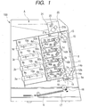
- FIG. 1 is a diagram showing the general construction of a color electrophotographic image forming apparatus according to an embodiment of the present invention
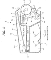
- FIG. 2 is an explanatory sectional view of a process cartridge
- FIG. 3 is a perspective view showing how the components of the process cartridge are put together.
- An image forming apparatus 100 shown in FIG. 1 , has four process cartridge attachment portions arranged side by side in the vertical direction, with each attachment portion having a developing roller separating means 8 (8a, 8b, 8c, 8d) constituting a separating means. Then, each of cartridges 7 (7a, 7b, 7c, 7d) respectively attached to the attachment portions is equipped with a drum-like electrophotographic photosensitive member serving as an image bearing member, that is, a photosensitive drum 1 (1a, 1b, 1c, 1d). Each photosensitive drum 1 is rotated counterclockwise as seen in FIG. 1 by a driving means (not shown). Around each photosensitive drum 1, the following components are arranged in the following order in the rotating direction.
- each photosensitive drum 1 Arranged around each photosensitive drum 1 are a charging means 2 (2a, 2b, 2c, 2d) serving as a charging member for uniformly charging the surface of the photosensitive drum 1, a scanner unit 3 (3a, 3b, 3c, 3d) for applying a laser beam based on image information to form an electrostatic latent image on the photosensitive drum 1, a developing unit 4 (4a, 4b, 4c, 4d) for forming a visible image, that is, a toner image by using toner constituting a developer for developing the electrostatic latent image, an electrostatic transfer means 12 (12a, 12b, 12c, 12d) serving as an electrostatic transfer means for transferring the toner image on the photosensitive drum 1 to a recording medium S, and a cleaning means 6 (6a, 6b, 6c, 6d) for removing toner remaining on the surface of the photosensitive drum 1 after transfer.
- a charging means 2 (2a, 2b, 2c, 2d) serving as a charging member for uniformly charging the
- the photosensitive drum 1, the charging means 2, the developing unit 4, and the cleaning means are integrated into a cartridge to form a process cartridge 7.
- the photosensitive drum 1 is formed by coating the outer peripheral surface of an aluminum cylinder having a diameter, for example, of 30 mm with an organic photoconductor layer (OPC photosensitive member).
- OPC photosensitive member organic photoconductor layer
- the photosensitive drum 1 is rotatably supported at both ends by bearings 31a and 31b ( FIG. 3 ).
- Drive force from a driving motor (not shown) is transmitted to one end portion of the photosensitive drum 1, whereby the photosensitive drum 1 is rotated counterclockwise (in the direction indicated by the arrow X in FIG. 2 ).
- the charging means 2 (2a, 2b, 2c, 2d) is a contact charging type as shown in FIG. 2 .
- the charging means 2 consists of a conductive roller formed into a roller shape, which is brought into contact with the surface of the photosensitive drum 1. Further, a charging bias voltage is applied to this charging roller 2, whereby the surface of the photosensitive drum 1 is uniformly charged.
- the scanner unit 3 (3a, 3b, 3c, 3d) is arranged substantially in the horizontal direction of the photosensitive drum 1.
- Image light corresponding to an image signal is applied by a laser diode (not shown) to a polygon mirror 9 (9a, 9b, 9c, 9d) rotated by a scanner motor (not shown).
- the image light reflected by the polygon mirror 9 is transmitted through an imaging lens 10 (10a, 10b, 10c, 10d) for selective exposure of the charged surface of the photosensitive drum 1, whereby an electrostatic latent image corresponding to the image signal is formed.
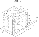
- the longitudinal length of the unit 3 is larger than the distance between right and left side plates 32.
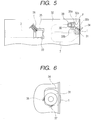
- protrusions 33 protrude from openings 35a, 35b, 35c, 35d, 35e, 35f, 35g, and 35h of the right and left side plates 32, wherein, as shown in FIG. 5 , the unit 3 is pressurized downwards by approximately 45 degrees by a compression spring 36 with a force of approximately 9.8 N, whereby the unit 3 is reliably pressed against an abutment portion and positioning is effected thereon.
- an electrostatic transfer belt 11 facing all the photosensitive drums 1a through 1d and circulating while being in contact therewith.
- the transfer belt 11 is a film-like member having a thickness of approximately 150 ⁇ m and a volume resistivity of 10 11 to 10 14 ⁇ cm.
- This transfer belt 11 is supported by four rollers arranged in the vertical direction. That is, the transfer belt 11 is stretched over four rollers: a driving roller 13, driven rollers 14a and 14b, and a tension roller 15, and runs in the direction indicated by the arrow in FIG. 1 , whereby the transfer belt 11 circulates and the recording medium S is conveyed past the transfer positions upwards from below in FIG. 1 .
- the transfer rollers 12 (12a, 12b, 12c, 12d) serving as the transfer means are held in contact with the inner side of the transfer belt 11 and arranged at positions opposed to the four photosensitive drums 1 (1a, 1b, 1c, 1d). Electric charge of positive polarity from the transfer rollers 12 is applied to the recording medium S through the transfer belt 11, whereby the toner images on the photosensitive drums 1 are transferred to the recording medium S.
- a feeding portion 16 serves to convey the recording medium S to an image forming portion.
- a plurality of recording mediums S is accommodated in a feeding cassette 17.
- a feeding roller 18 and a registration roller pair 19 rotate in accordance with the image forming operation. Accordingly, the recording mediums within the feeding cassette 17 are separated and fed sheet by sheet. Then, the leading edge of the recording medium S abuts against the registration roller pair 19 and stops temporarily. After that, in synchronism with the running of the transfer belt 11 and the toner images, the recording medium S is fed to the transfer belt 11 by the registration roller pair 19.
- a fixing portion 20 serves to fix toner images in a plurality of colors transferred to the recording medium S.
- the fixing portion 20 has a heating roller 21a that rotates, and a pressurizing roller 21b in pressure contact therewith and adapted to apply heat and pressure to the recording medium S. That is, the recording medium S, to which the toner images on the photosensitive drums 1 have been transferred, is conveyed by the fixing roller pair 21 (21a, 21b) when passing the fixing portion 20. Then, heat and pressure is imparted thereto by the fixing roller pair 21, whereby the toner images in a plurality of colors are fixed to the surface of the recording medium S.
- the image forming operation in the image forming apparatus of this embodiment is as follows.
- the cartridges 7 (7a, 7b, 7c, 7d) are successively driven timed with the image formation.
- the photosensitive drums 1 (1a, 1b, 1c, 1d) are rotated.
- the scanner units 3 (3a, 3b, 3c, 3d) respectively corresponding to the cartridges 7 (7a, 7b, 7c, 7d) are successively driven.
- the charging rollers 2 (2a, 2b, 2c, 2d) impart uniform electric charge to the surfaces of the photosensitive drums 1.
- the scanner units 3 perform exposure on the surfaces of the photosensitive drums 1 according to the image signal to form electrostatic latent images on the photosensitive drums 1.
- Developing rollers 40 serving as the developing members develop the electrostatic latent images.
- the toner images on the photosensitive drums 1 are successively transferred to the recording medium S by an electric field formed between the photosensitive drums 1 and the transfer rollers 12.
- the recording medium S to which the toner images in four colors have been transferred, is separated from the transfer belt 11, and then conveyed to the fixing portion 20. After the toner images are fixed thereto by heat in the fixing portion 20, the recording medium S is discharged to the exterior of the main body through a discharging portion 24 by a discharging roller 23.
- the cartridge 7a containing yellow toner, the cartridge 7b containing magenta toner, the cartridge 7c containing cyan toner, and the cartridge 7d containing black toner are of the same construction.
- each of the cartridges 7 (7a, 7b, 7c, 7d) is composed of a photosensitive member unit 50 as a first unit equipped with the charging roller 2 (2a, 2b, 2c, 2d) and the cleaning means 6 (6a, 6b, 6c, 6d), and a developing unit 4 (4a, 4b, 4c, 4d) as a second unit having the developing roller 40 (40a, 40b, 40c, 40d).
- the photosensitive drum and the developing roller are provided in different units, whereby it is possible to easily provide a toner seal for preventing leakage of toner from the process cartridge during the shipment thereof.
- the photosensitive drum 1 is rotatably mounted to a cleaning frame 51 through the intermediation of the bearings 31a and 31b.
- a primary charging roller 2 for uniformly charging the surface of the photosensitive drum 1
- a cleaning blade 60 serving as a cleaning means for removing the developer (toner) remaining on the photosensitive drum 1.
- the residual toner removed from the surface of the photosensitive drum 1 by the cleaning blade 60 is sent to a removed toner chamber 51a, provided at the rear of the cleaning frame, by a toner feeding mechanism 52. Then, by transmitting the drive force of the driving motor (not shown) to the photosensitive member unit 50, the photosensitive drum 1 is rotated in the direction indicated by the arrow X (counterclockwise) in accordance with the image forming operation.
- the charging member serves to charge the surface of the photosensitive drum 1.
- a so-called contact charging method as disclosed in JP 63-149669 A is employed. That is, the charging roller 2 is provided as the charging member in the cleaning frame 51 so as to be rotatable by slide bearings 61.
- the charging roller 2 is formed by providing an elastic rubber layer consisting of EPDM, NBR, or the like on a metal roller shaft 2a (for example, a conductive core formed of iron, SUS, or the like), and, further, providing on the peripheral surface thereof a urethane rubber layer in which carbon is dispersed, or coating the metal roller shaft with a foam urethane rubber layer in which carbon is dispersed.
- the roller shaft 2a of the charging roller 2 is mounted through the intermediation of the slide bearings 61 so as to be slidable toward the photosensitive drum 1 along a guide 61a provided inside the cleaning frame 51. Further, the charging roller 2 is urged toward the photosensitive drum 1 by a pressurizing spring 64 provided in a compressed state between the bearings 61 supporting the roller shaft 2a and the cleaning frame 51, and is thereby held in pressure contact with the surface of the photosensitive drum 1, whereby it rotates following the photosensitive drum 1. Further, at least one of the bearings 61 is formed of a conductive material, so that the surface of the photosensitive drum 1 is uniformly charged by applying a predetermined charging bias to the charging roller 2.
- each developing unit 4 (4a, 4b, 4c, 4d) has a developer containing portion containing developer (toner), that is, a toner container 41 (41a, 41b, 41c, 41d), and a developing frame, that is, a developing container 45 (45a, 45b, 45c, 45d).
- developer toner
- toner container 41 41a, 41b, 41c, 41d
- developing frame that is, a developing container 45 (45a, 45b, 45c, 45d).
- the yellow developing unit 4a has a toner container 41a containing yellow toner
- the magenta developing unit 4b has a toner container 41b containing magenta toner
- the cyan developing unit 4c has a toner container 41c containing cyan toner
- the black developing unit 4d has a toner container 41d containing black toner.
- the developing roller 40 opposed to the photosensitive drum 1 and serving as the developing member for carrying and conveying the developer.
- the developing roller 40 is rotatably supported by a developing frame 45 through the intermediation of bearing members 47 and 48, and rotates in the direction indicated by the arrow Y while in contact with the photosensitive drum 1.
- the developing roller 40 there are arranged the developing roller 40, a toner supply roller 43 (rotating in the direction indicated by the arrow Z), and a developing blade 44. Further, inside toner container 41, there is provided a toner conveying mechanism 42 for agitating the toner contained and conveying the toner to the toner supply roller 43. Further, at either end of the developing roller 40, there is arranged a spacer member (not shown) whose outer periphery is held in contact with the photosensitive drum 1 to thereby regulate the amount by which the developing roller 40 is held in pressure contact with the photosensitive drum 1 to a predetermined amount.
- the developing unit 4 has a suspension structure in which the entire developing unit 4 is supported so as to be swingable with respect to the photosensitive member unit 50. That is, the developing unit 4 is connected to the photosensitive member unit 50 so as to be rotatable around shafts 49 fitted into holes 47a and 48a respectively provided in the bearing members 47 and 48 mounted to the ends of the unit 4. As shown in FIG. 3 , the shafts 49 are firmly attached to holes 49a formed in the photosensitive member unit 50.
- the developing unit 4 is constantly urged so as to rotate counterclockwise as seen in FIGS. 2 and 7 around the shafts 49 by a pressurizing spring 54 (compression spring) and a pressurizing spring 53 (extension spring: see FIG. 11 ) serving as pressurizing members so that the developing roller 40 may be held in contact with the photosensitive drum 1 by rotation moment.
- a pressurizing spring 54 compression spring
- a pressurizing spring 53 extension spring: see FIG. 11
- the bearing members 47 and 48 of the developing unit 4 are integrally equipped with force receiving portions 46 for a cam 80 of a developing roller separating means 8 (described in detail below) to abut when separating the developing roller 40 from the photosensitive drum 1.
- the force receiving portions 46 are formed on the bearing members 47 and 48 at positions in the rear portion of the developing unit 4, that is, in the upstream portion of the toner container 41 with respect to the toner conveyance.
- the shafts 49 are arranged so as to be situated between the force receiving portions 46 and the developing roller 40.
- regulating portions 56 are provided on both side surfaces of the photosensitive member unit 50, and, in the state in which the process cartridge 7 has been inserted into the image forming apparatus main body 100, the regulating portions 56 are restrained to restraining portions 90 ( FIG. 13 ) provided on both side plates of the apparatus main body 100, regulating upward movement of the photosensitive member unit 50. Further, by pushing up the force receiving portions 46, the developing roller 40 is spaced apart from the photosensitive drum 1 by a predetermined gap (see FIG. 8 ).
- the photosensitive drum 1 In the contact developing system, in which development is effected with the photosensitive drum 1 and the developing roller 40 being held in contact with each other, it is desirable for the photosensitive drum 1 to be a rigid member and for the developing roller 40 to be a roller having an elastic member.
- the elastic member there is employed a solid rubber single layer, a solid rubber layer coated with resin, taking into account the requisite property for imparting charge to toner, or the like.
- the charging member releasing means also serves as a charging member moving means.
- one end of a link 58 is connected to the roller shaft 2a portion between the rubber portion and the slide bearing 61.
- the other end of each link 58 is connected to a crank 57 provided inside the cleaning frame 51.
- Each crank 57 is rotatably connected to a shaft 59 fitted into a bearing hole (not shown) formed in the cleaning frame 51.
- the bearing hole for the shaft 59 is provided on the opposite side of the photosensitive drum 1, with the developing unit swinging center shaft 49 being therebetween.
- the crank 57 has two arms 57a and 57b extending radially from the rotation center formed by the shaft 59.
- the angle ( ⁇ ) made by the two arms 57a and 57b is substantially a right angle.
- the distal end of the first arm 57a is rotatably connected to one end of the link 58 through the intermediation of a connection shaft 63.
- the second arm 57b has at its distal end an action receiving portion 65 in the form of a downwardly directed protrusion.
- cranks 57 rotate counterclockwise as seen in FIG. 7A , whereby the links 58 pulls both ends of the charging roller 2 to the left as seen in FIG. 7A , and the contact pressure of the charging roller 2 with respect to the photosensitive drum 1 is gradually reduced, until the charging roller is separated from the photosensitive drum 1.
- the bearing member 47, 48 of the developing unit 4 has at a position opposed to the action receiving portion 65 an acting portion 55 in the form of a protrusion.
- a gap W of several mm is provided beforehand between the action receiving portion 65 and the acting portion 55.
- the force receiving portion 46 receives a force from a cam 80 of the apparatus main body 100, solely the developing roller 40 is first separated from the photosensitive drum 1, and, at the same time, the acting portion 55 moves upwards (as shown in FIG. 8 ). At this time, the charging roller 2 and the photosensitive drum 1 are still in contact with each other. This position of the charging roller 2 will be referred to as a first position.
- the force receiving portion 46 on which the cam 80 acts, and the acting portion 55 in contact with the action receiving portion 65 constituting a part of the charging member releasing means are provided on each of the bearing members 47 and 48.
- the positions where the force receiving portion 46 and the acting portion 55 are provided are not restricted to those described above; it is also possible, for example, to provide them on the developing frame 45.
- by mounting the developing roller 40 to the bearing members 47 and 48 it is possible to minimize deflection of the components and variation in dimensional tolerance etc.
- the accuracy and responsiveness of the developing roller 40 and the charging roller 2 with respect to the input from the cam 80 are satisfactory, so that the stroke at the time of separation can be made a minimum one required, and it is possible to increase the paper passing speed, with the result that the printing speed can be increased.
- FIGS. 4 through 6 are diagrams illustrating how the process cartridge is attached to the image forming apparatus main body
- FIG. 7A is a diagram showing the state in which both the developing roller 40 and the charging roller 2 are in contact with the photosensitive drum 1 (first swinging attitude)
- FIG. 8 is a diagram showing the state in which the developing roller 40 is spaced apart from the photosensitive drum 1 while the charging roller 2 is in contact therewith (second swinging attitude)
- FIG. 9 is a diagram showing the state in which both the developing roller 40 and the charging roller 2 are spaced apart from the photosensitive drum 1 (third swinging attitude).
- the attachment of the process cartridge 7 to the apparatus main body 100 is effected by inserting the bearings 31 (31a and 31b) supporting both ends of the drum shaft of the photosensitive drum 1 in each cartridge 7 along guide grooves 34 (34a, 34b, 34c, 34d, 34e, 34f, 34g, and 34h).
- the attachment direction for the process cartridge 7 is indicated by the arrow A.
- the bearings 31 are pressed against abutment surfaces 37 and 38 of the guide grooves 34, whereby positioning of the process cartridge 7 with respect to the apparatus main body 100 is effected.
- the method pressurizing the process cartridge 7 inside the image forming apparatus main body 100 is as follows.
- a shaft 39 is crimped to apparatus main body side plates 32, and a helical torsion spring 30 is supported by the shaft 39.
- One end portion 30a of the spring 30 is fitted into a hole 32a for fixation, and the other end portion 30b is bent into a V-shape and abuts the bearings 31 (31a and 31b).
- the other end portion 30b of the spring 30 abuts a raised portion 32b, whereby its movement in the rotating direction is regulated.
- the spring 30 receives a raising force from the bearing 31, and rotates counterclockwise against the spring force.
- the bearing 31 gets over the V-shaped end portion 30b, the bearing 31 is elastically pressurized.
- the regulating portions 56 on both side surfaces of the photosensitive member unit 50 are restrained to the restraining portions 90 provided on both side surfaces of the image forming apparatus main body 100, so that upward movement of the photosensitive member unit 50 when the force receiving portions 46 are pushed up by the action of the cam 80 is regulated.
- the cam 80 for separating the developing roller 40 from the photosensitive drum 1 against the urging force of the developing unit 4.
- the cam 80 consists of cams 80 of the same configuration and the same phase connected to both longitudinal ends of a rotation shaft 80A.
- the cam 80 has a three-stage structure composed of a portion 80a with minimum radius, a portion 80b with medium radius, and a portion 80c with maximum radius.
- the states in which these stages are at the top are respectively referred to as lower, middle, and higher positions.
- the cam 80 is provided for each of the cartridges 7 of the colors of yellow, magenta, cyan, and black; they are drive-branched from one stepping motor (not shown) by gear connection, each being rotation-controlled in synchronism.
- the cam 80 is always rotated in the direction indicated by the arrow R in FIG. 7A . Due to this rotating direction, the photosensitive drum 1 is pulled rearwards, i.e., to the left as seen in FIG. 7A , that is, in the direction opposite to the transfer belt 11. Thus, no load or impact is applied to the transfer belt 11, which is advantageous from the viewpoint of misregister (in color).
- the charging roller 2 is spaced apart from the photosensitive drum 1 when the apparatus main body is at rest, if, as another embodiment, the contact pressure is lowered without achieving complete separation, it is also possible to achieve the same satisfactory effect as described above.
- the cam 80 rotates, in synchronism with the developing operation, in the direction indicated by the arrow R in FIG. 9 so as to assume the attitude shown in FIG. 7A , that is, the lower position mentioned above.
- the force receiving portion 46 is spaced apart from the cam 80, and the developing roller 40 is pressed against the photosensitive drum 1 with a predetermined pressure by the elastic force of the urging springs 53 and 54.
- the action receiving portion 65 is spaced apart from the acting portion 55, and the charging roller 2 is pressed against the photosensitive drum 1 with a predetermined pressure by the elastic force of the pressurizing spring 64. That is, the cam 80 is spaced apart from the force receiving portion 46, and the developing unit 4 assumes the first swinging attitude, whereby both the developing roller 40 and the charging roller 2 are held in contact with the photosensitive drum 1, making it possible to perform image formation.
- programming is effected such that a process for correcting image density is effected when the process cartridge 7 is attached to the image forming apparatus 100 or each time the apparatus has been used a predetermined number of times.
- a toner image is directly transferred to the surface of the electrostatic transfer belt 11, and the density of the image is detected by a density detection sensor, the potential at each image forming process being corrected in accordance with the density value.
- an electric field is formed so that the toner on the electrostatic transfer belt 11 may return to the photosensitive drum 1, the toner on the surface of the photosensitive drum 1 being accommodated in the removed toner chamber 51a of the cleaning frame 51.
- the developing roller 40 In the process of removing the toner on the surface of the electrostatic transfer belt 11, it is necessary for the developing roller 40 to be spaced apart while charging the surface of the photosensitive drum 1. If, in this process, the developing roller 40 is brought into contact with the photosensitive drum 1, much of the toner on the surface of the developing roller 40 will be borne by the surface of the photosensitive drum 1 due to the electric field between the developing roller 40 and the photosensitive drum 1, resulting in waste of toner.
- the cam 80 acts on the force receiving portion 46 and the developing unit 4 assumes the second swinging attitude, whereby the developing roller 40 is spaced apart from the photosensitive drum 1, and the charging roller 2 is held in contact therewith.
- the construction in which the developing roller 40 and the charging roller 2 can be separated as needed makes it possible to restrain toner consumption due to generation of image defect or fog caused by permanent deformation of the elastic member; further, it is effective in preventing the developing roller 40 from rotating more than necessary.
- the developing roller 40 is rotating while in contact with the photosensitive drum 1 and the toner supply roller 43, so that, as the developing roller 40 rotates, the toner deteriorates at the contact portions.
- it is possible to minimize the rotating time of the developing roller 40 it is possible to prevent image defect due to deterioration in the toner or toner leakage.
- a hook 66 is mounted to a side surface of the developing unit 4 so as to be rotatable around a shaft 66b.
- the photosensitive member unit 50 has, on the same side as the bearing member 47, a protrusion 67 with which the hook 66 is to be engaged.
- the protrusion 67 is situated such that in the state in which the hook 66 is engaged, the acting portion 55 pushes up the action receiving portion 65, that is, the developing unit 4 assumes the third swinging attitude.
- the hook 66 is engaged with the protrusion 67, so that both the developing roller 40 and the charging roller 2 are maintained in the state in which they are spaced apart from the photosensitive drum 1. That is, the hook 66 and the protrusion 67 constitute attitude maintaining members for maintaining the second frame, that is, the developing unit 4, in the third swinging attitude.
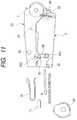
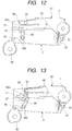
- the hook 66 has at its distal end a force receiving portion 66a, and the apparatus main body 100 has halfway through the insertion guide (not shown) a protrusion 71 acting on the force receiving portion 66a. Then, as the process cartridge 7 is inserted from the position of FIG. 11 into the apparatus main body 100 in the direction indicated by the arrow A, the force receiving portion 66a abuts the protrusion 71 at the position of FIG. 12 , and the hook 66 rotates in the direction indicated by the arrow N in FIG. 13 to be thereby detached from the protrusion 67, bringing the developing unit 40 into the state in which it can swing with respect to the photosensitive member unit 50.
- both the developing roller 40 and the charging roller 2 are maintained in the state in which they are spaced apart from the photosensitive drum 1 by the hook 66 and the protrusion 67, so that it is possible to prevent generation of image unevenness due to permanent deformation of the elastic layer and generation of transversal streaks in the image at an interval corresponding to the roller cycle due to rubbing memory during transportation.
- the hook 66 is automatically released as the process cartridge 7 is inserted into the apparatus main body 100, so that canceling can be reliably effected without causing any bother for the user.
- the hook 66 and the protrusion 67 are provided only one side surface of the process cartridge 7, it is desirable for them to be provided on both side surfaces of the cartridge 7, which makes it possible to more reliably maintain the separated state during shipment of the process cartridge.
- the cams 80 acting on the process cartridge 7 are of a three-stage construction, thereby making it possible for the developing unit 40 to assume three swinging attitudes. This makes it possible to selectively realize three states with respect to the photosensitive drum 1:
- the elastic rubber layer of the charging roller 2 does not easily undergo permanent deformation to involve problems regarding image formation even if the process cartridge 7 is left unused for a long period of time inside the image forming apparatus main body 100. In such cases, there is no need to separate the charging roller 2 from the photosensitive drum 1 inside the image forming apparatus main body 100, and it suffices to prevent solely the rubbing memory due to vibration during shipment.
- the cams 80 when the charging roller 2 is used, it is only necessary for the cams 80 to be of a two-stage construction so that the following two states with respect to the photosensitive drum 1 may be realized inside the image forming apparatus main body 100: (1) the state in which both the developing roller 40 and the charging roller 2 are in contact with it (first swinging attitude); and (2) the state in which only the developing roller 40 is in contact with it (second swinging attitude), making it possible to use the cam 80 having two acting portions: a portion 80a with minimum radius and a portion 80b with medium radius.
- the process cartridge 7 is constructed as in Embodiment 1, whereby, during shipment of the process cartridge, the developing roller 40 is enabled to assume the third swinging attitude by the hook 66, that is, by separating the developing roller 40 from the photosensitive drum 1 to a large degree, the action receiving portion 65 receives a force from the acting portion 55 of the developing unit 4 to effect interlocked movement, also enabling the charging roller 2 to be separated from the photosensitive drum 1, thus, making it possible to obtain the same effect as that of Embodiment 1.
- Embodiment 1 While in Embodiment 1 described above, there are provided in the first unit, that is, the photosensitive member unit 50, the links 58 and the cranks 57 as the charging member releasing means, the same effect can be achieved by some other construction. Another embodiment of the charging member releasing means will be described with reference to FIGS. 14 and 15 .
- one end of a wire 67 is connected to either end of the charging roller 2.
- the other end of each wire 67 is connected to a connecting portion 68 provided at the rear end portion of the cleaning frame 51.
- the wires 67 are stretched with slight slackening to a degree such that the charging roller 2 is not separated from the photosensitive drum 1 due to variation in dimensional tolerance.
- a rib 69 for regulating the wires 67.
- the distal end 69a of the rib 69 extends up to the vicinity of a straight line connecting the center of the charging roller 2 and the connecting portion 68 in the state in which the charging roller 2 is in contact with the photosensitive drum 1.
- the portions of the wires 67 between the connecting portion 68 and the distal end 69a of the rib constitute the action receiving portions 65; when the action receiving portions 65 are pushed up, the wires 67 pulls the charging roller 2 away from the photosensitive drum 1.
- the bearing members 47 and 48 of the developing unit 4 has the acting portions 55 in the form of protrusions at positions opposed to the action receiving portions 65.
- the wires 67 move together with the separating movement of the developing roller 40, enabling the charging roller 2 to be separated from the photosensitive drum 1.
- the charging roller 2 is provided in the photosensitive member unit 50, this should not be construed restrictively; it is also possible to provide the charging roller 2 in the developing unit 4.
- the photosensitive member unit is stationary and the developing unit is caused to swing
- the developing unit it is also possible for the developing unit to be stationary, causing the photosensitive member unit to swing; further, it is also possible to adopt a construction in which both the developing unit and the photosensitive member unit are caused to swing.
- the charging roller when the first swinging attitude and the second swinging attitude are assumed, the charging roller is at the first position, that is, the charging member is at the position where it is in contact with the photosensitive drum.
- the charging member is at the second position, that is, the charging roller is at the position where it is spaced apart from the photosensitive drum or at a position where the contact pressure of the charging roller with respect to the photosensitive drum is lower than that when it is at the first position.
Landscapes
- Engineering & Computer Science (AREA)
- Computer Vision & Pattern Recognition (AREA)
- Physics & Mathematics (AREA)
- General Physics & Mathematics (AREA)
- Life Sciences & Earth Sciences (AREA)
- Manufacturing & Machinery (AREA)
- Sustainable Development (AREA)
- Electrophotography Configuration And Component (AREA)
- Electrostatic Charge, Transfer And Separation In Electrography (AREA)
- Dry Development In Electrophotography (AREA)
Description
- The present invention relates to a process cartridge and an electrophotographic image forming apparatus using the same.
- Conventionally, in image forming apparatuses using an electrophotographic image forming process, there has been adopted a process cartridge system, in which an electrophotographic photosensitive member and a process means acting on the electrophotographic photosensitive member are integrated into a cartridge that is detachably mountable to a main body of an image forming apparatus. In the process cartridge system, maintenance on the apparatus can be conducted by a user himself without relying on a service man, thus achieving a substantial improvement in terms of operability. Thus, the process cartridge system is widely adopted in electrophotographic image forming apparatuses.
- Among the electrophotographic image forming apparatuses are in-line type color electrophotographic image forming apparatuses in which a plurality of process cartridges are arranged in a row. There is available a contact development system, in which a developing roller as a developing member constituting a developing means of each of such cartridges is held in contact, for example, with a drum-shaped electrophotographic photosensitive member, that is, a photosensitive drum, to effect development. To maintain a predetermined contact pressure between the developing roller and the photosensitive drum during image formation, the developing roller is urged against the photosensitive drum.
- In case of this system, if the image forming apparatus is left unused for a long period of time with the process cartridges attached to the main body of the image forming apparatus, there is a fear of an elastic layer of each developing roller undergoing permanent deformation, thereby generating image unevenness during development.
- As a construction for solving this problem, there have been proposed, in
JP 2900530 B JP 2001-337511 A - Apart from this, as a charging means for charging the surface of the photosensitive drum of a process cartridge for forming images by electrophotography, a corona charger has been widely put into practical use. Corona charging is effective as a method of charging a surface to be charged uniformly to a predetermined electric potential. However, it requires a high voltage power source, and involves problems such as ozone generation due to corona discharge.
- As a solution to this problem, there has been devised a contact charger for performing a charging process while keeping a charging roller as a charging member in contact with the surface of the photosensitive drum.
- Like the developing roller, if left unused for a long period of time, this contact charger may involve permanent deformation of the elastic layer of the charging roller, resulting in generation of transversal streaks in the image at intervals corresponding to the charging roller cycle. Further, due to vibration, surfaces of the charging roller and the photosensitive drum may rub each other, which leads to generation of a local difference in potential, i.e., so-called rubbing memory in the surface of the photosensitive drum. This may also lead to generation of transversal streaks in the image at intervals corresponding to the charging roller cycle.
- As means for avoiding this problem,
JP 5-188667 A US 5465136 andJP 2000-181328 A -
JP 2002-006722 A - It is an object of the present invention how to provide a process cartridge, which has a simple, inexpensive and space-saving structure.
- The object of the present invention is achieved by a process cartridge having the features of
claim 1. - Further advantageous developments of the present invention are defined in the dependent claims.
- Besides, an image forming apparatus comprising the process cartridge according to the present invention is shown in claim 14.
- In accordance with the present invention, there is no need to separately provide the image forming apparatus main body with a mechanism for separating the charging member, thereby making it possible to provide an inexpensive and space-saving process cartridge.
- Further, according to the present invention, solely by changing the swinging attitude of a first unit having an image bearing member and a charging member and a second unit having a developing member, it is possible to separate the developing member and the charging member from the image bearing member, whereby it is possible to obtain, with a simple construction, a stable image exhibiting no unevenness or transversal streaks.
-
-
FIG. 1 is a diagram showing the general construction of a color electrophotographic image forming apparatus according to an embodiment of the present invention; -
FIG. 2 is a schematic sectional view showing the construction of a process cartridge; -
FIG. 3 is a perspective view showing a connecting structure of a process cartridge; -
FIG. 4 is a diagram illustrating how a process cartridge is mounted to the main body of an image forming apparatus; -
FIG. 5 is a diagram illustrating how a process cartridge is mounted to the main body of an image forming apparatus; -
FIG. 6 is a diagram illustrating how a process cartridge is mounted to the main body of an image forming apparatus; -
FIG. 7A is a side view illustrating a mechanism for separating a charging roller and a developing roller from a photosensitive drum, showing a state (first swinging attitude) in which the charging roller and the developing roller are held in contact with the photosensitive drum, andFIG. 7B is a perspective view showing how a crank and a link are mounted; -
FIG. 8 is a side view showing a state (second swinging attitude) in which the charging roller is held in contact and the developing roller is held out of contact with the photosensitive drum; -
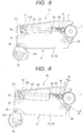
FIG. 9 is a side view showing a state (third swinging attitude) in which both the charging roller and the developing roller are separated apart from the photosensitive drum; -
FIG. 10 is a front view showing a support structure for a charging roller; -
FIG. 11 is a side view of a process cartridge, illustrating how it is inserted into the main body of an image forming apparatus; -
FIG. 12 is a side view of a process cartridge, illustrating how it is inserted into the main body of an image forming apparatus; -
FIG. 13 is a side view of a process cartridge, illustrating how it is inserted into the main body of an image forming apparatus; -
FIG. 14 is a side view of a charging roller separating mechanism of a process cartridge according to another embodiment of the present invention; and -
FIG. 15 is a side view of the process cartridge of the embodiment ofFIG. 14 , showing a state in which the charging roller is separated. - In the following, a process cartridge and a color electrophotographic image forming apparatus according to the present invention will be described in more detail with reference to the drawings.
- It is to be noted that, in the present invention, a process cartridge refers to what is obtained by integrating at least one of a charging means, a developing means, and a cleaning means with an electrophotographic photosensitive member into a cartridge, which is detachably mountable to the main body of an electrophotographic image forming apparatus.
-
FIG. 1 is a diagram showing the general construction of a color electrophotographic image forming apparatus according to an embodiment of the present invention,FIG. 2 is an explanatory sectional view of a process cartridge, andFIG. 3 is a perspective view showing how the components of the process cartridge are put together. - First, the general construction of an image forming apparatus will be described with reference to
FIG. 1 . Animage forming apparatus 100, shown inFIG. 1 , has four process cartridge attachment portions arranged side by side in the vertical direction, with each attachment portion having a developing roller separating means 8 (8a, 8b, 8c, 8d) constituting a separating means. Then, each of cartridges 7 (7a, 7b, 7c, 7d) respectively attached to the attachment portions is equipped with a drum-like electrophotographic photosensitive member serving as an image bearing member, that is, a photosensitive drum 1 (1a, 1b, 1c, 1d). Eachphotosensitive drum 1 is rotated counterclockwise as seen inFIG. 1 by a driving means (not shown). Around eachphotosensitive drum 1, the following components are arranged in the following order in the rotating direction. - Arranged around each
photosensitive drum 1 are a charging means 2 (2a, 2b, 2c, 2d) serving as a charging member for uniformly charging the surface of thephotosensitive drum 1, a scanner unit 3 (3a, 3b, 3c, 3d) for applying a laser beam based on image information to form an electrostatic latent image on thephotosensitive drum 1, a developing unit 4 (4a, 4b, 4c, 4d) for forming a visible image, that is, a toner image by using toner constituting a developer for developing the electrostatic latent image, an electrostatic transfer means 12 (12a, 12b, 12c, 12d) serving as an electrostatic transfer means for transferring the toner image on thephotosensitive drum 1 to a recording medium S, and a cleaning means 6 (6a, 6b, 6c, 6d) for removing toner remaining on the surface of thephotosensitive drum 1 after transfer. - In this embodiment, the
photosensitive drum 1, the charging means 2, the developingunit 4, and the cleaning means are integrated into a cartridge to form aprocess cartridge 7. - The
photosensitive drum 1 is formed by coating the outer peripheral surface of an aluminum cylinder having a diameter, for example, of 30 mm with an organic photoconductor layer (OPC photosensitive member). Thephotosensitive drum 1 is rotatably supported at both ends bybearings FIG. 3 ). Drive force from a driving motor (not shown) is transmitted to one end portion of thephotosensitive drum 1, whereby thephotosensitive drum 1 is rotated counterclockwise (in the direction indicated by the arrow X inFIG. 2 ). - In this embodiment, the charging means 2 (2a, 2b, 2c, 2d) is a contact charging type as shown in
FIG. 2 . Specifically, the charging means 2 consists of a conductive roller formed into a roller shape, which is brought into contact with the surface of thephotosensitive drum 1. Further, a charging bias voltage is applied to this chargingroller 2, whereby the surface of thephotosensitive drum 1 is uniformly charged. - The scanner unit 3 (3a, 3b, 3c, 3d) is arranged substantially in the horizontal direction of the
photosensitive drum 1. Image light corresponding to an image signal is applied by a laser diode (not shown) to a polygon mirror 9 (9a, 9b, 9c, 9d) rotated by a scanner motor (not shown). The image light reflected by the polygon mirror 9 is transmitted through an imaging lens 10 (10a, 10b, 10c, 10d) for selective exposure of the charged surface of thephotosensitive drum 1, whereby an electrostatic latent image corresponding to the image signal is formed. Further, as shown inFIG. 4 , the longitudinal length of theunit 3 is larger than the distance between right and leftside plates 32. As a result,protrusions 33 protrude fromopenings side plates 32, wherein, as shown inFIG. 5 , theunit 3 is pressurized downwards by approximately 45 degrees by acompression spring 36 with a force of approximately 9.8 N, whereby theunit 3 is reliably pressed against an abutment portion and positioning is effected thereon. - As shown in
FIG. 1 , in the image forming apparatus, there is arranged anelectrostatic transfer belt 11 facing all thephotosensitive drums 1a through 1d and circulating while being in contact therewith. Thetransfer belt 11 is a film-like member having a thickness of approximately 150 µm and a volume resistivity of 1011 to 1014 Ω·cm. - This
transfer belt 11 is supported by four rollers arranged in the vertical direction. That is, thetransfer belt 11 is stretched over four rollers: a drivingroller 13, drivenrollers tension roller 15, and runs in the direction indicated by the arrow inFIG. 1 , whereby thetransfer belt 11 circulates and the recording medium S is conveyed past the transfer positions upwards from below inFIG. 1 . - The transfer rollers 12 (12a, 12b, 12c, 12d) serving as the transfer means are held in contact with the inner side of the
transfer belt 11 and arranged at positions opposed to the four photosensitive drums 1 (1a, 1b, 1c, 1d). Electric charge of positive polarity from the transfer rollers 12 is applied to the recording medium S through thetransfer belt 11, whereby the toner images on thephotosensitive drums 1 are transferred to the recording medium S. - A feeding
portion 16 serves to convey the recording medium S to an image forming portion. A plurality of recording mediums S is accommodated in a feedingcassette 17. At the time of image formation, a feedingroller 18 and aregistration roller pair 19 rotate in accordance with the image forming operation. Accordingly, the recording mediums within the feedingcassette 17 are separated and fed sheet by sheet. Then, the leading edge of the recording medium S abuts against theregistration roller pair 19 and stops temporarily. After that, in synchronism with the running of thetransfer belt 11 and the toner images, the recording medium S is fed to thetransfer belt 11 by theregistration roller pair 19. - A fixing
portion 20 serves to fix toner images in a plurality of colors transferred to the recording medium S. The fixingportion 20 has aheating roller 21a that rotates, and a pressurizingroller 21b in pressure contact therewith and adapted to apply heat and pressure to the recording medium S. That is, the recording medium S, to which the toner images on thephotosensitive drums 1 have been transferred, is conveyed by the fixing roller pair 21 (21a, 21b) when passing the fixingportion 20. Then, heat and pressure is imparted thereto by the fixing roller pair 21, whereby the toner images in a plurality of colors are fixed to the surface of the recording medium S. - The image forming operation in the image forming apparatus of this embodiment is as follows.
- First, the cartridges 7 (7a, 7b, 7c, 7d) are successively driven timed with the image formation. In accordance with the driving, the photosensitive drums 1 (1a, 1b, 1c, 1d) are rotated. Then, the scanner units 3 (3a, 3b, 3c, 3d) respectively corresponding to the cartridges 7 (7a, 7b, 7c, 7d) are successively driven. By this driving, the charging rollers 2 (2a, 2b, 2c, 2d) impart uniform electric charge to the surfaces of the
photosensitive drums 1. After that, thescanner units 3 perform exposure on the surfaces of thephotosensitive drums 1 according to the image signal to form electrostatic latent images on thephotosensitive drums 1. Developingrollers 40 serving as the developing members develop the electrostatic latent images. - As stated above, the toner images on the
photosensitive drums 1 are successively transferred to the recording medium S by an electric field formed between thephotosensitive drums 1 and the transfer rollers 12. The recording medium S, to which the toner images in four colors have been transferred, is separated from thetransfer belt 11, and then conveyed to the fixingportion 20. After the toner images are fixed thereto by heat in the fixingportion 20, the recording medium S is discharged to the exterior of the main body through a dischargingportion 24 by a dischargingroller 23. - Next, the process cartridges 7 (7a, 7b, 7c, 7d) of the present invention will be described with reference to
FIGS. 2 and3 . - In this embodiment, the
cartridge 7a containing yellow toner, thecartridge 7b containing magenta toner, thecartridge 7c containing cyan toner, and thecartridge 7d containing black toner are of the same construction. - According to this embodiment, each of the cartridges 7 (7a, 7b, 7c, 7d) is composed of a
photosensitive member unit 50 as a first unit equipped with the charging roller 2 (2a, 2b, 2c, 2d) and the cleaning means 6 (6a, 6b, 6c, 6d), and a developing unit 4 (4a, 4b, 4c, 4d) as a second unit having the developing roller 40 (40a, 40b, 40c, 40d). In this way, the photosensitive drum and the developing roller are provided in different units, whereby it is possible to easily provide a toner seal for preventing leakage of toner from the process cartridge during the shipment thereof. - In the
photosensitive member unit 50, thephotosensitive drum 1 is rotatably mounted to acleaning frame 51 through the intermediation of thebearings photosensitive drum 1 are aprimary charging roller 2 for uniformly charging the surface of thephotosensitive drum 1 and acleaning blade 60 serving as a cleaning means for removing the developer (toner) remaining on thephotosensitive drum 1. - The residual toner removed from the surface of the
photosensitive drum 1 by thecleaning blade 60 is sent to a removedtoner chamber 51a, provided at the rear of the cleaning frame, by atoner feeding mechanism 52. Then, by transmitting the drive force of the driving motor (not shown) to thephotosensitive member unit 50, thephotosensitive drum 1 is rotated in the direction indicated by the arrow X (counterclockwise) in accordance with the image forming operation. - The charging member serves to charge the surface of the
photosensitive drum 1. In this embodiment, a so-called contact charging method as disclosed inJP 63-149669 A roller 2 is provided as the charging member in thecleaning frame 51 so as to be rotatable byslide bearings 61. The chargingroller 2 is formed by providing an elastic rubber layer consisting of EPDM, NBR, or the like on ametal roller shaft 2a (for example, a conductive core formed of iron, SUS, or the like), and, further, providing on the peripheral surface thereof a urethane rubber layer in which carbon is dispersed, or coating the metal roller shaft with a foam urethane rubber layer in which carbon is dispersed. Theroller shaft 2a of the chargingroller 2 is mounted through the intermediation of theslide bearings 61 so as to be slidable toward thephotosensitive drum 1 along aguide 61a provided inside thecleaning frame 51. Further, the chargingroller 2 is urged toward thephotosensitive drum 1 by a pressurizingspring 64 provided in a compressed state between thebearings 61 supporting theroller shaft 2a and thecleaning frame 51, and is thereby held in pressure contact with the surface of thephotosensitive drum 1, whereby it rotates following thephotosensitive drum 1. Further, at least one of thebearings 61 is formed of a conductive material, so that the surface of thephotosensitive drum 1 is uniformly charged by applying a predetermined charging bias to the chargingroller 2. - As will be seen with reference also to
FIG. 2 , each developing unit 4 (4a, 4b, 4c, 4d) has a developer containing portion containing developer (toner), that is, a toner container 41 (41a, 41b, 41c, 41d), and a developing frame, that is, a developing container 45 (45a, 45b, 45c, 45d). - That is, regarding the
toner container 41, the yellow developingunit 4a has a toner container 41a containing yellow toner, themagenta developing unit 4b has a toner container 41b containing magenta toner, thecyan developing unit 4c has a toner container 41c containing cyan toner, and the black developingunit 4d has a toner container 41d containing black toner. In eachtoner container 41, there is arranged the developingroller 40 opposed to thephotosensitive drum 1 and serving as the developing member for carrying and conveying the developer. - The developing
roller 40 is rotatably supported by a developingframe 45 through the intermediation of bearingmembers photosensitive drum 1. - Further, as stated above, in the periphery of the developing
roller 40, there are arranged the developingroller 40, a toner supply roller 43 (rotating in the direction indicated by the arrow Z), and a developingblade 44. Further, insidetoner container 41, there is provided atoner conveying mechanism 42 for agitating the toner contained and conveying the toner to thetoner supply roller 43. Further, at either end of the developingroller 40, there is arranged a spacer member (not shown) whose outer periphery is held in contact with thephotosensitive drum 1 to thereby regulate the amount by which the developingroller 40 is held in pressure contact with thephotosensitive drum 1 to a predetermined amount. - The developing
unit 4 has a suspension structure in which the entire developingunit 4 is supported so as to be swingable with respect to thephotosensitive member unit 50. That is, the developingunit 4 is connected to thephotosensitive member unit 50 so as to be rotatable aroundshafts 49 fitted intoholes members unit 4. As shown inFIG. 3 , theshafts 49 are firmly attached toholes 49a formed in thephotosensitive member unit 50. - Further, when the
cartridge 7 is alone (i.e., in the state in which it is not attached to the apparatus main body 100), the developingunit 4 is constantly urged so as to rotate counterclockwise as seen inFIGS. 2 and7 around theshafts 49 by a pressurizing spring 54 (compression spring) and a pressurizing spring 53 (extension spring: seeFIG. 11 ) serving as pressurizing members so that the developingroller 40 may be held in contact with thephotosensitive drum 1 by rotation moment. - Further, as will be seen with reference to
FIGS. 3 and7 , the bearingmembers unit 4 are integrally equipped withforce receiving portions 46 for acam 80 of a developing roller separating means 8 (described in detail below) to abut when separating the developingroller 40 from thephotosensitive drum 1. Theforce receiving portions 46 are formed on the bearingmembers unit 4, that is, in the upstream portion of thetoner container 41 with respect to the toner conveyance. Further, theshafts 49 are arranged so as to be situated between theforce receiving portions 46 and the developingroller 40. - As shown in
FIG. 3 , regulatingportions 56 are provided on both side surfaces of thephotosensitive member unit 50, and, in the state in which theprocess cartridge 7 has been inserted into the image forming apparatusmain body 100, the regulatingportions 56 are restrained to restraining portions 90 (FIG. 13 ) provided on both side plates of the apparatusmain body 100, regulating upward movement of thephotosensitive member unit 50. Further, by pushing up theforce receiving portions 46, the developingroller 40 is spaced apart from thephotosensitive drum 1 by a predetermined gap (seeFIG. 8 ). - In the contact developing system, in which development is effected with the
photosensitive drum 1 and the developingroller 40 being held in contact with each other, it is desirable for thephotosensitive drum 1 to be a rigid member and for the developingroller 40 to be a roller having an elastic member. As the elastic member, there is employed a solid rubber single layer, a solid rubber layer coated with resin, taking into account the requisite property for imparting charge to toner, or the like. - Next, the construction of the charging member releasing means, which constitutes a feature of the present invention, will be described with reference mainly to
FIG. 7 . In this embodiment, the charging member releasing means also serves as a charging member moving means. - First, as shown in
FIG. 10 , at either end of the chargingroller 2, one end of alink 58 is connected to theroller shaft 2a portion between the rubber portion and theslide bearing 61. As can be seen fromFIGS. 7A and 7B , the other end of eachlink 58 is connected to a crank 57 provided inside thecleaning frame 51. - Each crank 57 is rotatably connected to a
shaft 59 fitted into a bearing hole (not shown) formed in thecleaning frame 51. As shown inFIG. 7A , the bearing hole for theshaft 59 is provided on the opposite side of thephotosensitive drum 1, with the developing unit swingingcenter shaft 49 being therebetween. - The
crank 57 has twoarms shaft 59. The angle (α) made by the twoarms first arm 57a is rotatably connected to one end of thelink 58 through the intermediation of aconnection shaft 63. Thesecond arm 57b has at its distal end anaction receiving portion 65 in the form of a downwardly directed protrusion. - Thus, by pushing up the
action receiving portions 65, thecranks 57 rotate counterclockwise as seen inFIG. 7A , whereby thelinks 58 pulls both ends of the chargingroller 2 to the left as seen inFIG. 7A , and the contact pressure of the chargingroller 2 with respect to thephotosensitive drum 1 is gradually reduced, until the charging roller is separated from thephotosensitive drum 1. - The bearing
member unit 4 has at a position opposed to theaction receiving portion 65 an actingportion 55 in the form of a protrusion. When the developingroller 40 is in contact with the photosensitive drum 1 (as shown inFIG. 7A ), a gap W of several mm is provided beforehand between theaction receiving portion 65 and the actingportion 55. When theforce receiving portion 46 receives a force from acam 80 of the apparatusmain body 100, solely the developingroller 40 is first separated from thephotosensitive drum 1, and, at the same time, the actingportion 55 moves upwards (as shown inFIG. 8 ). At this time, the chargingroller 2 and thephotosensitive drum 1 are still in contact with each other. This position of the chargingroller 2 will be referred to as a first position. - When the
force receiving portion 46 is further pushed up, the actingportion 55 pushes up theaction receiving portion 65, and the contact pressure of the chargingroller 2 with respect to thephotosensitive drum 1 is reduced, until the charging roller is separated from the photosensitive drum 1 (as shown inFIG. 9 ). This position at which the contact pressure of the chargingroller 2 with respect to thephotosensitive drum 1 is lower than that at the first position or the position at which the chargingroller 2 is spaced apart from thephotosensitive drum 1 will be referred to as a second position. - In this embodiment, the
force receiving portion 46 on which thecam 80 acts, and the actingportion 55 in contact with theaction receiving portion 65 constituting a part of the charging member releasing means are provided on each of the bearingmembers force receiving portion 46 and the actingportion 55 are provided are not restricted to those described above; it is also possible, for example, to provide them on the developingframe 45. However, as in this embodiment, by mounting the developingroller 40 to the bearingmembers roller 40 and the chargingroller 2 with respect to the input from thecam 80 are satisfactory, so that the stroke at the time of separation can be made a minimum one required, and it is possible to increase the paper passing speed, with the result that the printing speed can be increased. - Next, the separating mechanism to be used when the
process cartridge 7 is attached to the apparatusmain body 100 with reference toFIGS. 4 through 9 . -
FIGS. 4 through 6 are diagrams illustrating how the process cartridge is attached to the image forming apparatus main body,FIG. 7A is a diagram showing the state in which both the developingroller 40 and the chargingroller 2 are in contact with the photosensitive drum 1 (first swinging attitude),FIG. 8 is a diagram showing the state in which the developingroller 40 is spaced apart from thephotosensitive drum 1 while the chargingroller 2 is in contact therewith (second swinging attitude), andFIG. 9 is a diagram showing the state in which both the developingroller 40 and the chargingroller 2 are spaced apart from the photosensitive drum 1 (third swinging attitude). - First, the attachment of the
process cartridge 7 to the apparatusmain body 100 is effected by inserting the bearings 31 (31a and 31b) supporting both ends of the drum shaft of thephotosensitive drum 1 in eachcartridge 7 along guide grooves 34 (34a, 34b, 34c, 34d, 34e, 34f, 34g, and 34h). InFIG. 4 , the attachment direction for theprocess cartridge 7 is indicated by the arrow A. Then, as shown inFIG. 6 , thebearings 31 are pressed against abutment surfaces 37 and 38 of theguide grooves 34, whereby positioning of theprocess cartridge 7 with respect to the apparatusmain body 100 is effected. - The method pressurizing the
process cartridge 7 inside the image forming apparatusmain body 100 is as follows. - As shown in
FIG. 5 , ashaft 39 is crimped to apparatus mainbody side plates 32, and ahelical torsion spring 30 is supported by theshaft 39. Oneend portion 30a of thespring 30 is fitted into ahole 32a for fixation, and theother end portion 30b is bent into a V-shape and abuts the bearings 31 (31a and 31b). In the state in which thecartridge 7 has not been attached yet, theother end portion 30b of thespring 30 abuts a raisedportion 32b, whereby its movement in the rotating direction is regulated. When theprocess cartridge 7 is inserted, thespring 30 receives a raising force from thebearing 31, and rotates counterclockwise against the spring force. When thebearing 31 gets over the V-shapedend portion 30b, thebearing 31 is elastically pressurized. - At this time, as stated above, the regulating
portions 56 on both side surfaces of thephotosensitive member unit 50 are restrained to the restrainingportions 90 provided on both side surfaces of the image forming apparatusmain body 100, so that upward movement of thephotosensitive member unit 50 when theforce receiving portions 46 are pushed up by the action of thecam 80 is regulated. - As shown in
FIGS. 7A ,8, and 9 , on the inner side of the apparatusmain body 100 with respect to the inserting direction of thecartridge 7, there is arranged thecam 80 for separating the developingroller 40 from thephotosensitive drum 1 against the urging force of the developingunit 4. - The
cam 80 consists ofcams 80 of the same configuration and the same phase connected to both longitudinal ends of arotation shaft 80A. Thecam 80 has a three-stage structure composed of aportion 80a with minimum radius, aportion 80b with medium radius, and aportion 80c with maximum radius. In this embodiment, the states in which these stages are at the top are respectively referred to as lower, middle, and higher positions. - In this embodiment, the radius of the minimum-
radius portion 80a of thecam 80 is such that, in the state in which the developingroller 40 is in contact with thephotosensitive drum 1, there is a gap T between it and theforce receiving portion 46; the medium-radius portion 80b is such that, while it is in contact with theforce receiving portion 46, there is a gap W between the actingportion 55 of the bearingmembers action receiving portion 65. Then, the radius of the maximum-radius portion 80c is such that it is in contact with theforce receiving portion 46 and that the actingportion 55 of the bearingmembers action receiving portion 65, that is, T = W = 0. - The
cam 80 is provided for each of thecartridges 7 of the colors of yellow, magenta, cyan, and black; they are drive-branched from one stepping motor (not shown) by gear connection, each being rotation-controlled in synchronism. - Further, the
cam 80 is always rotated in the direction indicated by the arrow R inFIG. 7A . Due to this rotating direction, thephotosensitive drum 1 is pulled rearwards, i.e., to the left as seen inFIG. 7A , that is, in the direction opposite to thetransfer belt 11. Thus, no load or impact is applied to thetransfer belt 11, which is advantageous from the viewpoint of misregister (in color). - As shown in
FIG. 9 , when the image forming apparatusmain body 100 is at rest, thecam 80 is in the higher position mentioned above. At this time, theforce receiving portion 46 is pushed up by the actingportion 80c of thecam 80, and the developingroller 40 is spaced apart from thephotosensitive drum 1 by a distance L as shown inFIG. 9 . Then, the action receiving portion is also pushed up by the actingportion 55 of the bearingmembers roller 2 is also spaced apart from thephotosensitive drum 1 by a distance M as shown inFIG. 9 . - In this way, when the apparatus
main body 100 is at rest, thecam 80 acts on theforce receiving portion 46, and the developingunit 4 assumes the third swinging attitude (the state as shown inFIG. 9 ), whereby both the developingroller 40 and the chargingroller 2 are spaced apart from thephotosensitive drum 1. Thus, even if theprocess cartridge 7 attached to the image forming apparatusmain body 100 is left unused for a long period of time, the elastic layer does no undergo permanent deformation, so that it is possible to avoid generation of transversal streaks in the image at an interval corresponding to the roller cycle. - While in this embodiment the charging
roller 2 is spaced apart from thephotosensitive drum 1 when the apparatus main body is at rest, if, as another embodiment, the contact pressure is lowered without achieving complete separation, it is also possible to achieve the same satisfactory effect as described above. - Further, while in this embodiment it is possible to assume all of the first, second, and third swinging attitudes due to the
cam 80, it is also possible to adopt a construction in which it is possible to assume the first and second swinging attitudes by thecam 80, the third swinging attitude being assumed by means of ahook 66 described below. - Next, when image forming operation is started by a print signal, the
cam 80 rotates, in synchronism with the developing operation, in the direction indicated by the arrow R inFIG. 9 so as to assume the attitude shown inFIG. 7A , that is, the lower position mentioned above. In this state, theforce receiving portion 46 is spaced apart from thecam 80, and the developingroller 40 is pressed against thephotosensitive drum 1 with a predetermined pressure by the elastic force of the urging springs 53 and 54. Then, theaction receiving portion 65 is spaced apart from the actingportion 55, and the chargingroller 2 is pressed against thephotosensitive drum 1 with a predetermined pressure by the elastic force of the pressurizingspring 64. That is, thecam 80 is spaced apart from theforce receiving portion 46, and the developingunit 4 assumes the first swinging attitude, whereby both the developingroller 40 and the chargingroller 2 are held in contact with thephotosensitive drum 1, making it possible to perform image formation. - In the cartridge attitude during image forming operation, there is a gap W between the
action receiving portion 65 and the actingportion 55, so that, during transition from the stop state to the start of image forming operation, the chargingroller 2 always comes into contact with thephotosensitive drum 1 first, and then the developingroller 40 comes into contact with thephotosensitive drum 1. When the image forming operation has been completed, the developingroller 40 and the chargingroller 2 are spaced apart from thephotosensitive drum 1 again; in this process, the developingroller 40 is always separated from thephotosensitive drum 1 first, and then the chargingroller 2 is separated from thephotosensitive drum 1. - Due to this contact order, while the developing
roller 40 is in contact with thephotosensitive drum 1, it is possible to maintain a state in which uniform electric charge is imparted to the surface of thephotosensitive drum 1. If, conversely, the chargingroller 2 is separated from thephotosensitive drum 1 earlier than the developingroller 40, the toner on the developingroller 40 is inadvertently borne by the surface of thephotosensitive drum 1, resulting in an image defect such as fog. Here, the chargingroller 2 in the second swinging attitude is brought into contact with thephotosensitive drum 1 to start to charge thephotosensitive drum 1. When, as a result of rotation of thephotosensitive drum 1, the charged region of thephotosensitive drum 1 reaches the position where it faces the developingroller 40, switching to the first swinging attitude is effected to bring the developingroller 40 into contact with thephotosensitive drum 1. That is, when the developingroller 40 comes into contact with thephotosensitive drum 1, it is so arranged that the region already charged by the chargingroller 2 comes into contact, whereby it is possible to reliably prevent fogging of toner from the developingroller 40 to thephotosensitive drum 1. - Further, in this embodiment, programming is effected such that a process for correcting image density is effected when the
process cartridge 7 is attached to theimage forming apparatus 100 or each time the apparatus has been used a predetermined number of times. In the above-mentioned process, a toner image is directly transferred to the surface of theelectrostatic transfer belt 11, and the density of the image is detected by a density detection sensor, the potential at each image forming process being corrected in accordance with the density value. After the completion of the detection, an electric field is formed so that the toner on theelectrostatic transfer belt 11 may return to thephotosensitive drum 1, the toner on the surface of thephotosensitive drum 1 being accommodated in the removedtoner chamber 51a of thecleaning frame 51. In the process of removing the toner on the surface of theelectrostatic transfer belt 11, it is necessary for the developingroller 40 to be spaced apart while charging the surface of thephotosensitive drum 1. If, in this process, the developingroller 40 is brought into contact with thephotosensitive drum 1, much of the toner on the surface of the developingroller 40 will be borne by the surface of thephotosensitive drum 1 due to the electric field between the developingroller 40 and thephotosensitive drum 1, resulting in waste of toner. Thus, as shown inFIG. 8 , in this process, thecam 80 acts on theforce receiving portion 46 and the developingunit 4 assumes the second swinging attitude, whereby the developingroller 40 is spaced apart from thephotosensitive drum 1, and the chargingroller 2 is held in contact therewith. - As stated above, the construction in which the developing
roller 40 and the chargingroller 2 can be separated as needed makes it possible to restrain toner consumption due to generation of image defect or fog caused by permanent deformation of the elastic member; further, it is effective in preventing the developingroller 40 from rotating more than necessary. In particular, in the case of theprocess cartridge 7 in a color electrophotographic image forming apparatus, the developingroller 40 is rotating while in contact with thephotosensitive drum 1 and thetoner supply roller 43, so that, as the developingroller 40 rotates, the toner deteriorates at the contact portions. Thus, in the construction of this embodiment, in which it is possible to minimize the rotating time of the developingroller 40, it is possible to prevent image defect due to deterioration in the toner or toner leakage. - Next, a construction for separating the
photosensitive drum 1 from the developingroller 40 and the chargingroller 2 during shipment of theprocess cartridge 7 and a construction for canceling the separation will be described with reference toFIGS. 11 through 13 . - As shown in
FIG. 13 , ahook 66 is mounted to a side surface of the developingunit 4 so as to be rotatable around ashaft 66b. On the other hand, thephotosensitive member unit 50 has, on the same side as the bearingmember 47, aprotrusion 67 with which thehook 66 is to be engaged. Theprotrusion 67 is situated such that in the state in which thehook 66 is engaged, the actingportion 55 pushes up theaction receiving portion 65, that is, the developingunit 4 assumes the third swinging attitude. Thus, during shipment of the process cartridge, thehook 66 is engaged with theprotrusion 67, so that both the developingroller 40 and the chargingroller 2 are maintained in the state in which they are spaced apart from thephotosensitive drum 1. That is, thehook 66 and theprotrusion 67 constitute attitude maintaining members for maintaining the second frame, that is, the developingunit 4, in the third swinging attitude. - The
hook 66 has at its distal end aforce receiving portion 66a, and the apparatusmain body 100 has halfway through the insertion guide (not shown) aprotrusion 71 acting on theforce receiving portion 66a. Then, as theprocess cartridge 7 is inserted from the position ofFIG. 11 into the apparatusmain body 100 in the direction indicated by the arrow A, theforce receiving portion 66a abuts theprotrusion 71 at the position ofFIG. 12 , and thehook 66 rotates in the direction indicated by the arrow N inFIG. 13 to be thereby detached from theprotrusion 67, bringing the developingunit 40 into the state in which it can swing with respect to thephotosensitive member unit 50. When, thereafter, the process cartridge is 7 is further inserted in the direction indicated by the arrow A, the regulatingportions 56 of thephotosensitive member unit 50 are restrained by the restrainingportions 90 provided on both side plates of the image forming apparatusmain body 100 as shown inFIG. 13 , and theforce receiving portions 46 of the developingunit 40 ride on the actingportions 80c of thecams 80 serving as the separating means, thus completing the attachment of theprocess cartridge 7. - In the above-described construction, during shipment of the process cartridge, both the developing
roller 40 and the chargingroller 2 are maintained in the state in which they are spaced apart from thephotosensitive drum 1 by thehook 66 and theprotrusion 67, so that it is possible to prevent generation of image unevenness due to permanent deformation of the elastic layer and generation of transversal streaks in the image at an interval corresponding to the roller cycle due to rubbing memory during transportation. Then, thehook 66 is automatically released as theprocess cartridge 7 is inserted into the apparatusmain body 100, so that canceling can be reliably effected without causing any bother for the user. - While in this embodiment, described above, the
hook 66 and theprotrusion 67 are provided only one side surface of theprocess cartridge 7, it is desirable for them to be provided on both side surfaces of thecartridge 7, which makes it possible to more reliably maintain the separated state during shipment of the process cartridge. - In the image forming apparatus main body of
Embodiment 1 described above, thecams 80 acting on theprocess cartridge 7 are of a three-stage construction, thereby making it possible for the developingunit 40 to assume three swinging attitudes. This makes it possible to selectively realize three states with respect to the photosensitive drum 1: - (1) the state in which both the developing
roller 40 and the chargingroller 2 are in contact with it (first swinging attitude); - (2) the state in which only the developing
roller 40 is separated from it (second swinging attitude); and - (3) the state in which both the developing
roller 40 and the chargingroller 2 are separated from it (third swinging attitude). - However, when, for example, the hardness of the elastic rubber layer of the charging
roller 2 is low to some degree, the elastic rubber layer does not easily undergo permanent deformation to involve problems regarding image formation even if theprocess cartridge 7 is left unused for a long period of time inside the image forming apparatusmain body 100. In such cases, there is no need to separate the chargingroller 2 from thephotosensitive drum 1 inside the image forming apparatusmain body 100, and it suffices to prevent solely the rubbing memory due to vibration during shipment. - Thus, when the charging
roller 2 is used, it is only necessary for thecams 80 to be of a two-stage construction so that the following two states with respect to thephotosensitive drum 1 may be realized inside the image forming apparatus main body 100: (1) the state in which both the developingroller 40 and the chargingroller 2 are in contact with it (first swinging attitude); and (2) the state in which only the developingroller 40 is in contact with it (second swinging attitude), making it possible to use thecam 80 having two acting portions: aportion 80a with minimum radius and aportion 80b with medium radius. - In the above-described construction also, the
process cartridge 7 is constructed as inEmbodiment 1, whereby, during shipment of the process cartridge, the developingroller 40 is enabled to assume the third swinging attitude by thehook 66, that is, by separating the developingroller 40 from thephotosensitive drum 1 to a large degree, theaction receiving portion 65 receives a force from the actingportion 55 of the developingunit 4 to effect interlocked movement, also enabling the chargingroller 2 to be separated from thephotosensitive drum 1, thus, making it possible to obtain the same effect as that ofEmbodiment 1. - While in
Embodiment 1 described above, there are provided in the first unit, that is, thephotosensitive member unit 50, thelinks 58 and thecranks 57 as the charging member releasing means, the same effect can be achieved by some other construction. Another embodiment of the charging member releasing means will be described with reference toFIGS. 14 and 15 . - First, one end of a
wire 67 is connected to either end of the chargingroller 2. The other end of eachwire 67 is connected to a connectingportion 68 provided at the rear end portion of thecleaning frame 51. Thewires 67 are stretched with slight slackening to a degree such that the chargingroller 2 is not separated from thephotosensitive drum 1 due to variation in dimensional tolerance. Here, inside thecleaning frame 51, there is provided arib 69 for regulating thewires 67. Thedistal end 69a of therib 69 extends up to the vicinity of a straight line connecting the center of the chargingroller 2 and the connectingportion 68 in the state in which the chargingroller 2 is in contact with thephotosensitive drum 1. - The portions of the
wires 67 between the connectingportion 68 and thedistal end 69a of the rib constitute theaction receiving portions 65; when theaction receiving portions 65 are pushed up, thewires 67 pulls the chargingroller 2 away from thephotosensitive drum 1. On the other hand, the bearingmembers unit 4 has the actingportions 55 in the form of protrusions at positions opposed to theaction receiving portions 65. - When the
force receiving portions 46 receive force from thecams 80 of the apparatusmain body 100, solely the developingroller 40 is first separated from thephotosensitive drum 1. At the same time, the actingportions 55 move upwards. Then, when theforce receiving portions 46 are further pushed up, the actingportions 55 push up theaction receiving portions 65, and the contact pressure of the chargingroller 2 with respect to thephotosensitive drum 1 is reduced, until the chargingroller 2 is separated as shown inFIG. 15 . - Thus, in the above construction also, as in
Embodiment 1, thewires 67 move together with the separating movement of the developingroller 40, enabling the chargingroller 2 to be separated from thephotosensitive drum 1. - While in the above embodiments the charging
roller 2 is provided in thephotosensitive member unit 50, this should not be construed restrictively; it is also possible to provide the chargingroller 2 in the developingunit 4. - While in this embodiment the photosensitive member unit is stationary and the developing unit is caused to swing, this should not be construed restrictively. For example, it is also possible for the developing unit to be stationary, causing the photosensitive member unit to swing; further, it is also possible to adopt a construction in which both the developing unit and the photosensitive member unit are caused to swing.
- In this embodiment, when the first swinging attitude and the second swinging attitude are assumed, the charging roller is at the first position, that is, the charging member is at the position where it is in contact with the photosensitive drum. When the third swinging attitude is assumed, the charging member is at the second position, that is, the charging roller is at the position where it is spaced apart from the photosensitive drum or at a position where the contact pressure of the charging roller with respect to the photosensitive drum is lower than that when it is at the first position.
Claims (14)
- A process cartridge (7) detachably mountable to an image forming apparatus main body (100), said process cartridge (7) comprising:an image bearing member (1);a charging member (2) for charging the image bearing member (1);a developing member (40) for developing an electrostatic latent image formed on the image bearing member (1);a first unit (50) having the image bearing member (1) and the charging member (2);a second unit (4) swingably supported by said first unit (50) and having said developing member (40); anda movable member (57, 58, 65) provided in said first unit (50) so as to be movable between a first position and a second position with respect to said first unit (50) and configured to move said charging member (2),wherein said charging member (2) contacts said image bearing member (1) when said movable member (57, 58, 65) is in said first position,wherein, when said movable member (57, 58, 65) is in said second position, a contact pressure of said charging member (2) against said image bearing member (1) is reduced in comparison with when said movable member (57, 58, 65) is in said first position or said charging member (2) is separated from said image bearing member (1),wherein said second unit (4) is configured to swing with respect to said first unit (50) so that said second unit (4) can assume a contacting position in which said second unit (4) is configured to bring said developing member (40) into contact with said image bearing member (1) and a separating position in which said second unit (4) is configured to separate said developing member (40) from said image bearing member (1),wherein said second unit (4) is configured to move from said contacting position to said separating position so that said second unit (4) is brought into contact with said movable member (57, 58, 65) to move said movable member (57, 58, 65) from said first position to said second position, andwherein said second unit (4) is configured to move from said separating position to said contacting position so as to permit said movable member (57, 58, 65) to move from said second position to said first position.
- A process cartridge (7) according to claim 1, wherein said movable member (57, 58, 65) is a rotatable member which rotates to move between said first position and said second position.
- A process cartridge (7) according to claim 2, wherein a rotation center, formed by a shaft (59), of said movable member (57, 58, 65) with respect to said first unit (50) and a swinging rotation center shaft (49) of said second unit (4) with respect to said first unit (50) are disposed in different positions such that the shaft (59) is provided on the opposite side of the image bearing member (1) and the swinging rotation center shaft (49) is provided between the shaft (59) and the image bearing member (1).
- A process cartridge (7) according to any one of claims 1 to 3, wherein said second unit (4) has an acting portion (55) contactable with said movable member (57, 58, 65), and
wherein, in case said movable member (57, 58, 65) is brought into contact with said acting portion (55) to receive a force from said acting portion (55), the movable member (57, 58, 65) is configured to move from said first position to said second position. - A process cartridge (7) according to claim 4, wherein said acting portion (55) is provided on a bearing member (47, 48) rotatably supporting said developing member (40).
- A process cartridge (7) according to any one of claims 1 to 5, wherein one of said first unit (50) and said second unit (4) has a force receiving portion (46) adapted to receive a force from separating means (80) provided in the image forming apparatus main body (100) for moving said developing member (40) away from said image bearing member (1), and
wherein in case said process cartridge (7) is attached to the image forming apparatus main body (100), said second unit (4) can selectively assume said contacting position and said separating position by an action of said separating means (80). - A process cartridge (7) according to claim 6, wherein said force receiving portion (46) is provided on a bearing member (47, 48) rotatably supporting said developing member (40).
- A process cartridge (7) according to any one of claims 1 to 7, further comprising a position maintaining member (66, 67) for maintaining said second unit (4) in said separating position.
- A process cartridge (7) according to any one of claims 1 to 7, further comprising a pressurizing member (53) for applying a pressurizing force between said first unit (50) and said second unit (4) so as to press said developing member (40) against said image bearing member (1).
- A process cartridge (7) according to any one of claims 1 to 9, wherein said charging member (2) is configured to effect charging while being in contact with said image bearing member (1).
- A process cartridge (7) according to any one of claims 1 to 9, wherein said movable member (57, 58, 65) is configured to reduce a contact pressure of said charging member (2) against said image bearing member (1) when said movable member (57, 58, 65) is in said second position.
- A process cartridge (7) according to any one of claims 1 to 9, wherein said movable member (57, 58, 65) is configured to separate said charging member (2) from said image bearing member (1) when said movable member (57, 58, 65) is in said second position.
- A process cartridge (7) according to any one of claims 1 to 12, wherein said charging member (2) is configured to effect charging while being in contact with said image bearing member (1).
- An image forming apparatus for forming an image on a recording medium (S), comprising:an image forming apparatus main body (100);a process cartridge (7) according to any of the preceding claims, which is detachably mountable to said main body (100); andseparating means (80) adapted to be brought into contact with said process cartridge (7) mounted in said main body (100), for causing said second unit (4) to selectively assume said contacting position and said separating position.
Applications Claiming Priority (2)
| Application Number | Priority Date | Filing Date | Title |
|---|---|---|---|
| JP2003334197A JP3958272B2 (en) | 2003-09-25 | 2003-09-25 | Process cartridge and electrophotographic image forming apparatus |
| EP04013492.6A EP1519248B1 (en) | 2003-09-25 | 2004-06-08 | Process cartridge and electrophotographic image forming apparatus |
Related Parent Applications (2)
| Application Number | Title | Priority Date | Filing Date |
|---|---|---|---|
| EP04013492.6A Division-Into EP1519248B1 (en) | 2003-09-25 | 2004-06-08 | Process cartridge and electrophotographic image forming apparatus |
| EP04013492.6A Division EP1519248B1 (en) | 2003-09-25 | 2004-06-08 | Process cartridge and electrophotographic image forming apparatus |
Publications (2)
| Publication Number | Publication Date |
|---|---|
| EP2706414A1 EP2706414A1 (en) | 2014-03-12 |
| EP2706414B1 true EP2706414B1 (en) | 2017-08-09 |
Family
ID=34191500
Family Applications (2)
| Application Number | Title | Priority Date | Filing Date |
|---|---|---|---|
| EP13193022.4A Expired - Lifetime EP2706414B1 (en) | 2003-09-25 | 2004-06-08 | Process cartridge and electrophotographic image forming apparatus |
| EP04013492.6A Expired - Lifetime EP1519248B1 (en) | 2003-09-25 | 2004-06-08 | Process cartridge and electrophotographic image forming apparatus |
Family Applications After (1)
| Application Number | Title | Priority Date | Filing Date |
|---|---|---|---|
| EP04013492.6A Expired - Lifetime EP1519248B1 (en) | 2003-09-25 | 2004-06-08 | Process cartridge and electrophotographic image forming apparatus |
Country Status (5)
| Country | Link |
|---|---|
| US (1) | US6980759B2 (en) |
| EP (2) | EP2706414B1 (en) |
| JP (1) | JP3958272B2 (en) |
| KR (1) | KR100561574B1 (en) |
| CN (1) | CN100365526C (en) |
Families Citing this family (70)
| Publication number | Priority date | Publication date | Assignee | Title |
|---|---|---|---|---|
| JP3970279B2 (en) * | 2004-07-30 | 2007-09-05 | キヤノン株式会社 | Process cartridge and electrophotographic image forming apparatus |
| JP3962734B2 (en) * | 2004-08-31 | 2007-08-22 | キヤノン株式会社 | Mounting mechanism for detachably mounting the process cartridge to the main body of the electrophotographic image forming apparatus |
| US7305194B2 (en) * | 2004-11-30 | 2007-12-04 | Xerox Corporation | Xerographic device streak failure recovery |
| JP4865341B2 (en) * | 2005-02-04 | 2012-02-01 | キヤノン株式会社 | Process cartridge and electrophotographic image forming apparatus |
| JP3986077B2 (en) | 2005-03-18 | 2007-10-03 | キヤノン株式会社 | Process cartridge and electrophotographic image forming apparatus |
| JP4040636B2 (en) * | 2005-03-24 | 2008-01-30 | キヤノン株式会社 | Process cartridge and electrophotographic image forming apparatus |
| JP4695913B2 (en) * | 2005-04-12 | 2011-06-08 | キヤノン株式会社 | Electrophotographic image forming apparatus |
| US7221888B2 (en) * | 2005-04-24 | 2007-05-22 | Hewlett-Packard Development Company, L.P. | Printing device cartridge having position in which rollers are separated from photoconductor |
| JP4280753B2 (en) | 2005-04-27 | 2009-06-17 | キヤノン株式会社 | Electrophotographic image forming apparatus and process cartridge |
| KR100693338B1 (en) * | 2005-09-08 | 2007-03-09 | 삼성전자주식회사 | Process cartridge and image forming apparatus having same |
| JP4661507B2 (en) | 2005-09-30 | 2011-03-30 | ブラザー工業株式会社 | Image forming apparatus |
| JP4280770B2 (en) | 2006-01-11 | 2009-06-17 | キヤノン株式会社 | Process cartridge and electrophotographic image forming apparatus |
| CN101371202B (en) * | 2006-01-11 | 2011-07-20 | 佳能株式会社 | Process cartridge and image forming apparatus |
| JP4927451B2 (en) * | 2006-06-16 | 2012-05-09 | 株式会社リコー | Process cartridge and image forming apparatus |
| JP5559397B2 (en) * | 2006-06-26 | 2014-07-23 | キヤノン株式会社 | Process cartridge, support member, and process cartridge assembly method |
| JP4241865B2 (en) * | 2006-12-08 | 2009-03-18 | キヤノン株式会社 | Process cartridge and electrophotographic image forming apparatus |
| JP4464435B2 (en) | 2006-12-11 | 2010-05-19 | キヤノン株式会社 | Process cartridge and electrophotographic image forming apparatus |
| AU2011254084B2 (en) * | 2006-12-11 | 2012-08-16 | Canon Kabushiki Kaisha | Developing apparatus, process cartridge and electrophotographic image forming apparatus |
| JP5147371B2 (en) * | 2006-12-11 | 2013-02-20 | キヤノン株式会社 | Process cartridge and image forming apparatus |
| JP4444997B2 (en) * | 2006-12-11 | 2010-03-31 | キヤノン株式会社 | Process cartridge and electrophotographic image forming apparatus |
| JP4444999B2 (en) * | 2006-12-11 | 2010-03-31 | キヤノン株式会社 | Developing device, process cartridge, and electrophotographic image forming apparatus |
| JP5288769B2 (en) * | 2006-12-11 | 2013-09-11 | キヤノン株式会社 | Image forming apparatus |
| US7929881B2 (en) * | 2006-12-11 | 2011-04-19 | Canon Kabushiki Kaisha | Process cartridge and electrophotographic image forming apparatus |
| US7983589B2 (en) * | 2007-01-31 | 2011-07-19 | Canon Kabushiki Kaisha | Developing apparatus, process cartridge, and image forming apparatus |
| US7903994B2 (en) * | 2007-05-15 | 2011-03-08 | Canon Kabushiki Kaisha | Image forming apparatus |
| JP4458378B2 (en) * | 2007-06-29 | 2010-04-28 | キヤノン株式会社 | Process cartridge and electrophotographic image forming apparatus |
| JP4882010B2 (en) * | 2007-06-29 | 2012-02-22 | キヤノン株式会社 | Process cartridge and electrophotographic image forming apparatus |
| JP4882009B2 (en) * | 2007-06-29 | 2012-02-22 | キヤノン株式会社 | Process cartridge and electrophotographic image forming apparatus |
| JP4458377B2 (en) | 2007-06-29 | 2010-04-28 | キヤノン株式会社 | Process cartridge and electrophotographic image forming apparatus |
| JP2009048138A (en) * | 2007-08-23 | 2009-03-05 | Konica Minolta Business Technologies Inc | Imaging cartridge and image forming apparatus |
| JP4968957B2 (en) * | 2008-03-31 | 2012-07-04 | キヤノン株式会社 | Frame body unit, developing device and process cartridge, and frame body unit, developing device and process cartridge manufacturing method |
| JP4869289B2 (en) * | 2008-05-27 | 2012-02-08 | キヤノン株式会社 | Process cartridge and electrophotographic image forming apparatus |
| JP5219626B2 (en) * | 2008-05-27 | 2013-06-26 | キヤノン株式会社 | Process cartridge and image forming apparatus |
| JP5127567B2 (en) * | 2008-05-27 | 2013-01-23 | キヤノン株式会社 | Process cartridge |
| JP5111238B2 (en) * | 2008-05-27 | 2013-01-09 | キヤノン株式会社 | Process cartridge |
| JP4701266B2 (en) * | 2008-05-27 | 2011-06-15 | キヤノン株式会社 | Process cartridge and electrophotographic image forming apparatus |
| JP5344538B2 (en) * | 2008-05-27 | 2013-11-20 | キヤノン株式会社 | Process cartridge assembling method, process cartridge disassembling method, process cartridge remanufacturing method, and process cartridge |
| JP5121573B2 (en) * | 2008-05-27 | 2013-01-16 | キヤノン株式会社 | Process cartridge and image forming apparatus |
| JP5328230B2 (en) * | 2008-06-10 | 2013-10-30 | キヤノン株式会社 | Cartridge and electrophotographic image forming apparatus using the cartridge |
| JP5195259B2 (en) * | 2008-10-10 | 2013-05-08 | コニカミノルタビジネステクノロジーズ株式会社 | Image forming apparatus |
| JP2011123348A (en) * | 2009-12-11 | 2011-06-23 | Canon Inc | Process cartridge and method for disassembling process cartridge |
| JP5693213B2 (en) | 2010-01-13 | 2015-04-01 | キヤノン株式会社 | Drum support mechanism, process cartridge, and electrophotographic image forming apparatus |
| JP5517732B2 (en) | 2010-05-11 | 2014-06-11 | キヤノン株式会社 | Process cartridge and image forming apparatus |
| JP5517989B2 (en) | 2010-05-14 | 2014-06-11 | キヤノン株式会社 | Process cartridge and image forming apparatus |
| CN201837835U (en) * | 2010-10-22 | 2011-05-18 | 珠海天威飞马打印耗材有限公司 | A treatment box |
| JP5293753B2 (en) * | 2011-01-14 | 2013-09-18 | ブラザー工業株式会社 | Image forming apparatus |
| JP5812751B2 (en) | 2011-08-05 | 2015-11-17 | キヤノン株式会社 | Process cartridge |
| CN102955393A (en) * | 2011-08-25 | 2013-03-06 | 株式会社理光 | Imaging device |
| JP5987282B2 (en) * | 2011-08-30 | 2016-09-07 | ブラザー工業株式会社 | Process cartridge |
| JP5919766B2 (en) * | 2011-11-30 | 2016-05-18 | ブラザー工業株式会社 | Process cartridge |
| JP5355679B2 (en) | 2011-12-27 | 2013-11-27 | キヤノン株式会社 | Process cartridge and image forming apparatus |
| JP5943685B2 (en) | 2012-04-13 | 2016-07-05 | キヤノン株式会社 | Developing unit, process cartridge, and electrophotographic image forming apparatus |
| JP5518125B2 (en) * | 2012-04-26 | 2014-06-11 | キヤノン株式会社 | Electrophotographic image forming apparatus |
| PL2863271T3 (en) | 2012-06-15 | 2019-11-29 | Canon Kk | Cartridge, process cartridge, and electrophotographic image generation device |
| JP6338460B2 (en) | 2013-08-20 | 2018-06-06 | キヤノン株式会社 | Cartridge and image forming apparatus |
| JP6376749B2 (en) | 2013-12-06 | 2018-08-22 | キヤノン株式会社 | Process cartridge and electrophotographic image forming apparatus |
| JP6671997B2 (en) | 2015-02-05 | 2020-03-25 | キヤノン株式会社 | Cartridge, photoreceptor unit, electrophotographic image forming apparatus |
| JP6598468B2 (en) | 2015-02-16 | 2019-10-30 | キヤノン株式会社 | Cartridge, image forming apparatus, and cartridge manufacturing method |
| JP6552212B2 (en) | 2015-02-16 | 2019-07-31 | キヤノン株式会社 | Cartridge, image forming apparatus, and method of manufacturing cartridge |
| JP6486145B2 (en) * | 2015-02-27 | 2019-03-20 | キヤノン株式会社 | Cartridge and image forming apparatus |
| JP6723694B2 (en) | 2015-07-01 | 2020-07-15 | キヤノン株式会社 | Image forming apparatus and cartridge |
| JP2017151358A (en) * | 2016-02-26 | 2017-08-31 | 富士ゼロックス株式会社 | Image forming assembly and image forming apparatus |
| KR20180008220A (en) * | 2016-07-15 | 2018-01-24 | 에스프린팅솔루션 주식회사 | electrophotographic image forming apparatus and method detecting release of development nip |
| CN109716241B (en) | 2016-08-26 | 2021-11-09 | 佳能株式会社 | Drum unit, cartridge, electrophotographic image forming apparatus, and coupling member |
| RU2019108099A (en) | 2016-08-26 | 2020-09-28 | Кэнон Кабусики Кайся | DRUM ASSEMBLY, CARTRIDGE, ELECTROPHOTOGRAPHIC IMAGER AND COUPLING ELEMENT |
| JP2018200357A (en) | 2017-05-26 | 2018-12-20 | キヤノン株式会社 | cartridge |
| CN211293617U (en) * | 2018-09-18 | 2020-08-18 | 卢敬坤 | Processing box |
| JP7262983B2 (en) | 2018-11-30 | 2023-04-24 | キヤノン株式会社 | Process cartridge and image forming apparatus |
| JP7305417B2 (en) | 2019-04-25 | 2023-07-10 | キヤノン株式会社 | Process cartridge and image forming apparatus |
| CN113671810A (en) * | 2020-05-14 | 2021-11-19 | 江西亿铂电子科技有限公司 | Developing box |
Family Cites Families (29)
| Publication number | Priority date | Publication date | Assignee | Title |
|---|---|---|---|---|
| JPS56155952A (en) * | 1980-05-02 | 1981-12-02 | Minolta Camera Co Ltd | Electronic copier |
| US4851960A (en) | 1986-12-15 | 1989-07-25 | Canon Kabushiki Kaisha | Charging device |
| JPS63149669A (en) | 1986-12-15 | 1988-06-22 | Canon Inc | Contact electric charging method |
| JP2900530B2 (en) | 1990-06-11 | 1999-06-02 | 松下電器産業株式会社 | Printing device |
| JPH05188667A (en) | 1992-01-07 | 1993-07-30 | Canon Inc | Process cartridge and recorder |
| JP3073102B2 (en) * | 1992-09-28 | 2000-08-07 | 富士通株式会社 | Process cartridge and image forming apparatus |
| JPH06273987A (en) | 1993-03-23 | 1994-09-30 | Canon Inc | Process cartridge and image forming device |
| JP2877729B2 (en) | 1994-04-28 | 1999-03-31 | キヤノン株式会社 | Shutter member, process cartridge, and image forming apparatus |
| JPH0815940A (en) | 1994-04-28 | 1996-01-19 | Canon Inc | Developing frame, process cartridge and image forming device |
| JP2877728B2 (en) | 1994-04-28 | 1999-03-31 | キヤノン株式会社 | Process cartridge and image forming apparatus |
| US6070029A (en) | 1995-07-31 | 2000-05-30 | Canon Kabushiki Kaisha | Coupling member, process cartridge, electrophotographic image forming apparatus and assembling method |
| US5893006A (en) | 1995-07-31 | 1999-04-06 | Canon Kabushiki Kaisha | Process cartridge detectably mountable to image forming apparatus and image forming apparatus using same |
| JP3402860B2 (en) | 1995-07-31 | 2003-05-06 | キヤノン株式会社 | Process cartridge and electrophotographic image forming apparatus |
| JPH09134108A (en) * | 1995-11-08 | 1997-05-20 | Casio Electron Mfg Co Ltd | Process unit and image forming device using the same |
| US5950049A (en) | 1996-03-05 | 1999-09-07 | Canon Kabushiki Kaisha | Developing cartridge |
| JP3332818B2 (en) | 1996-08-29 | 2002-10-07 | キヤノン株式会社 | Process cartridge, electrophotographic image forming apparatus, and connection terminal connection method |
| JP3745111B2 (en) | 1997-03-18 | 2006-02-15 | キヤノン株式会社 | Coupling member, process cartridge, and process cartridge assembly method |
| JP2000029371A (en) * | 1998-07-08 | 2000-01-28 | Canon Inc | Image forming device |
| JP3893222B2 (en) | 1998-08-31 | 2007-03-14 | キヤノン株式会社 | Shutter pin and developer cartridge |
| JP2000075733A (en) | 1998-08-31 | 2000-03-14 | Canon Inc | Method for mounting electrophotographic photoreceptor drum, method for replacing the same, and process cartridge |
| JP3658202B2 (en) | 1998-08-31 | 2005-06-08 | キヤノン株式会社 | Developing cartridge assembly method |
| JP2000131945A (en) | 1998-10-26 | 2000-05-12 | Canon Inc | Developing device and process cartridge |
| JP2000181328A (en) | 1998-12-17 | 2000-06-30 | Canon Inc | Locking member, process cartridge and electrophotographic image forming device |
| JP2001337511A (en) | 2000-05-26 | 2001-12-07 | Matsushita Electric Ind Co Ltd | Color image forming device |
| JP2002006722A (en) | 2000-06-27 | 2002-01-11 | Canon Inc | Process cartridge, separating member, and electrophotographic image forming device |
| JP3442047B2 (en) | 2000-11-17 | 2003-09-02 | キヤノン株式会社 | Process cartridge and electrophotographic image forming apparatus |
| JP3566697B2 (en) * | 2001-02-09 | 2004-09-15 | キヤノン株式会社 | Process cartridge, electrophotographic image forming apparatus, and separation mechanism |
| JP4194298B2 (en) | 2002-05-17 | 2008-12-10 | キヤノン株式会社 | Information storage medium, unit, process cartridge, developing cartridge, and electrophotographic image forming apparatus |
| US6801733B2 (en) * | 2003-01-21 | 2004-10-05 | Static Control Components, Inc. | Printer cartridge and method of making or refurbishing |
-
2003
- 2003-09-25 JP JP2003334197A patent/JP3958272B2/en not_active Expired - Fee Related
-
2004
- 2004-04-30 US US10/835,116 patent/US6980759B2/en not_active Expired - Fee Related
- 2004-06-08 EP EP13193022.4A patent/EP2706414B1/en not_active Expired - Lifetime
- 2004-06-08 EP EP04013492.6A patent/EP1519248B1/en not_active Expired - Lifetime
- 2004-07-21 CN CNB2004100709758A patent/CN100365526C/en not_active Expired - Fee Related
- 2004-09-21 KR KR1020040075297A patent/KR100561574B1/en not_active IP Right Cessation
Also Published As
| Publication number | Publication date |
|---|---|
| KR20050030554A (en) | 2005-03-30 |
| EP1519248A1 (en) | 2005-03-30 |
| JP3958272B2 (en) | 2007-08-15 |
| CN1601401A (en) | 2005-03-30 |
| EP1519248B1 (en) | 2015-05-27 |
| EP2706414A1 (en) | 2014-03-12 |
| US20050069342A1 (en) | 2005-03-31 |
| JP2005099517A (en) | 2005-04-14 |
| KR100561574B1 (en) | 2006-03-17 |
| CN100365526C (en) | 2008-01-30 |
| US6980759B2 (en) | 2005-12-27 |
Similar Documents
| Publication | Publication Date | Title |
|---|---|---|
| EP2706414B1 (en) | Process cartridge and electrophotographic image forming apparatus | |
| JP3566697B2 (en) | Process cartridge, electrophotographic image forming apparatus, and separation mechanism | |
| JP4164293B2 (en) | Developing device, process cartridge, and image forming apparatus | |
| US5440373A (en) | Color image forming apparatus | |
| US9632479B2 (en) | Process cartridge and image forming apparatus | |
| US6704528B1 (en) | Image forming apparatus having detachable cleaning unit | |
| US20060159487A1 (en) | Developing cartridge and electrophotographic image forming apparatus employing the same | |
| US20100202796A1 (en) | Development device, process unit, and image forming apparatus | |
| JP2006292868A (en) | Image forming apparatus | |
| JP2002189401A (en) | Process cartridge and electrophotographic image forming device | |
| JP4345802B2 (en) | Multicolor image forming apparatus | |
| US6654583B2 (en) | Developing apparatus | |
| JP2004341118A (en) | Processing cartridge and picture formation system | |
| JP2006215117A (en) | Image forming apparatus | |
| US7142794B2 (en) | Image forming apparatus | |
| JP2006301673A (en) | Image forming apparatus | |
| JP2003195720A (en) | Unit for image forming apparatus, process cartridge, and the image forming apparatus | |
| JP2003205649A (en) | Imaging apparatus | |
| JP4669275B2 (en) | Image forming apparatus | |
| US20070104514A1 (en) | Image forming method and printing method thereof | |
| JP2005172906A (en) | Process cartridge and electrophotographic image forming apparatus | |
| JP2005091792A (en) | Process cartridge and image forming apparatus | |
| JP3958314B2 (en) | Cleaning device, process cartridge, and electrophotographic image forming apparatus | |
| JP2003295596A (en) | Developer detection method, developing device, process cartridge and image forming apparatus | |
| JP2004037914A (en) | Process cartridge and image forming device |
Legal Events
| Date | Code | Title | Description |
|---|---|---|---|
| PUAI | Public reference made under article 153(3) epc to a published international application that has entered the european phase |
Free format text: ORIGINAL CODE: 0009012 |
|
| AC | Divisional application: reference to earlier application |
Ref document number: 1519248 Country of ref document: EP Kind code of ref document: P |
|
| AK | Designated contracting states |
Kind code of ref document: A1 Designated state(s): DE FR GB |
|
| 17P | Request for examination filed |
Effective date: 20140912 |
|
| RBV | Designated contracting states (corrected) |
Designated state(s): DE FR GB |
|
| 17Q | First examination report despatched |
Effective date: 20160608 |
|
| GRAP | Despatch of communication of intention to grant a patent |
Free format text: ORIGINAL CODE: EPIDOSNIGR1 |
|
| INTG | Intention to grant announced |
Effective date: 20170207 |
|
| GRAS | Grant fee paid |
Free format text: ORIGINAL CODE: EPIDOSNIGR3 |
|
| GRAA | (expected) grant |
Free format text: ORIGINAL CODE: 0009210 |
|
| AC | Divisional application: reference to earlier application |
Ref document number: 1519248 Country of ref document: EP Kind code of ref document: P |
|
| AK | Designated contracting states |
Kind code of ref document: B1 Designated state(s): DE FR GB |
|
| REG | Reference to a national code |
Ref country code: GB Ref legal event code: FG4D |
|
| REG | Reference to a national code |
Ref country code: DE Ref legal event code: R096 Ref document number: 602004051658 Country of ref document: DE |
|
| REG | Reference to a national code |
Ref country code: DE Ref legal event code: R097 Ref document number: 602004051658 Country of ref document: DE |
|
| PLBE | No opposition filed within time limit |
Free format text: ORIGINAL CODE: 0009261 |
|
| STAA | Information on the status of an ep patent application or granted ep patent |
Free format text: STATUS: NO OPPOSITION FILED WITHIN TIME LIMIT |
|
| REG | Reference to a national code |
Ref country code: FR Ref legal event code: PLFP Year of fee payment: 15 |
|
| 26N | No opposition filed |
Effective date: 20180511 |
|
| PGFP | Annual fee paid to national office [announced via postgrant information from national office to epo] |
Ref country code: FR Payment date: 20190625 Year of fee payment: 16 |
|
| PGFP | Annual fee paid to national office [announced via postgrant information from national office to epo] |
Ref country code: GB Payment date: 20190627 Year of fee payment: 16 Ref country code: DE Payment date: 20190830 Year of fee payment: 16 |
|
| REG | Reference to a national code |
Ref country code: DE Ref legal event code: R119 Ref document number: 602004051658 Country of ref document: DE |
|
| GBPC | Gb: european patent ceased through non-payment of renewal fee |
Effective date: 20200608 |
|
| PG25 | Lapsed in a contracting state [announced via postgrant information from national office to epo] |
Ref country code: FR Free format text: LAPSE BECAUSE OF NON-PAYMENT OF DUE FEES Effective date: 20200630 Ref country code: GB Free format text: LAPSE BECAUSE OF NON-PAYMENT OF DUE FEES Effective date: 20200608 |
|
| PG25 | Lapsed in a contracting state [announced via postgrant information from national office to epo] |
Ref country code: DE Free format text: LAPSE BECAUSE OF NON-PAYMENT OF DUE FEES Effective date: 20210101 |