EP2706373B1 - Combined FMCW and FM pulse-compression radar systems and methods - Google Patents
Combined FMCW and FM pulse-compression radar systems and methods Download PDFInfo
- Publication number
- EP2706373B1 EP2706373B1 EP13182422.9A EP13182422A EP2706373B1 EP 2706373 B1 EP2706373 B1 EP 2706373B1 EP 13182422 A EP13182422 A EP 13182422A EP 2706373 B1 EP2706373 B1 EP 2706373B1
- Authority
- EP
- European Patent Office
- Prior art keywords
- signal
- mode
- synthesizer
- pulse
- receiver
- Prior art date
- Legal status (The legal status is an assumption and is not a legal conclusion. Google has not performed a legal analysis and makes no representation as to the accuracy of the status listed.)
- Active
Links
Images


Classifications
-
- G—PHYSICS
- G01—MEASURING; TESTING
- G01S—RADIO DIRECTION-FINDING; RADIO NAVIGATION; DETERMINING DISTANCE OR VELOCITY BY USE OF RADIO WAVES; LOCATING OR PRESENCE-DETECTING BY USE OF THE REFLECTION OR RERADIATION OF RADIO WAVES; ANALOGOUS ARRANGEMENTS USING OTHER WAVES
- G01S13/00—Systems using the reflection or reradiation of radio waves, e.g. radar systems; Analogous systems using reflection or reradiation of waves whose nature or wavelength is irrelevant or unspecified
- G01S13/02—Systems using reflection of radio waves, e.g. primary radar systems; Analogous systems
- G01S13/06—Systems determining position data of a target
- G01S13/08—Systems for measuring distance only
- G01S13/10—Systems for measuring distance only using transmission of interrupted, pulse modulated waves
- G01S13/26—Systems for measuring distance only using transmission of interrupted, pulse modulated waves wherein the transmitted pulses use a frequency- or phase-modulated carrier wave
- G01S13/28—Systems for measuring distance only using transmission of interrupted, pulse modulated waves wherein the transmitted pulses use a frequency- or phase-modulated carrier wave with time compression of received pulses
- G01S13/284—Systems for measuring distance only using transmission of interrupted, pulse modulated waves wherein the transmitted pulses use a frequency- or phase-modulated carrier wave with time compression of received pulses using coded pulses
- G01S13/286—Systems for measuring distance only using transmission of interrupted, pulse modulated waves wherein the transmitted pulses use a frequency- or phase-modulated carrier wave with time compression of received pulses using coded pulses frequency shift keyed
-
- G—PHYSICS
- G01—MEASURING; TESTING
- G01S—RADIO DIRECTION-FINDING; RADIO NAVIGATION; DETERMINING DISTANCE OR VELOCITY BY USE OF RADIO WAVES; LOCATING OR PRESENCE-DETECTING BY USE OF THE REFLECTION OR RERADIATION OF RADIO WAVES; ANALOGOUS ARRANGEMENTS USING OTHER WAVES
- G01S13/00—Systems using the reflection or reradiation of radio waves, e.g. radar systems; Analogous systems using reflection or reradiation of waves whose nature or wavelength is irrelevant or unspecified
- G01S13/02—Systems using reflection of radio waves, e.g. primary radar systems; Analogous systems
- G01S13/06—Systems determining position data of a target
- G01S13/08—Systems for measuring distance only
- G01S13/32—Systems for measuring distance only using transmission of continuous waves, whether amplitude-, frequency-, or phase-modulated, or unmodulated
-
- G—PHYSICS
- G01—MEASURING; TESTING
- G01S—RADIO DIRECTION-FINDING; RADIO NAVIGATION; DETERMINING DISTANCE OR VELOCITY BY USE OF RADIO WAVES; LOCATING OR PRESENCE-DETECTING BY USE OF THE REFLECTION OR RERADIATION OF RADIO WAVES; ANALOGOUS ARRANGEMENTS USING OTHER WAVES
- G01S13/00—Systems using the reflection or reradiation of radio waves, e.g. radar systems; Analogous systems using reflection or reradiation of waves whose nature or wavelength is irrelevant or unspecified
- G01S13/88—Radar or analogous systems specially adapted for specific applications
- G01S13/93—Radar or analogous systems specially adapted for specific applications for anti-collision purposes
- G01S13/937—Radar or analogous systems specially adapted for specific applications for anti-collision purposes of marine craft
-
- H—ELECTRICITY
- H03—ELECTRONIC CIRCUITRY
- H03L—AUTOMATIC CONTROL, STARTING, SYNCHRONISATION OR STABILISATION OF GENERATORS OF ELECTRONIC OSCILLATIONS OR PULSES
- H03L2207/00—Indexing scheme relating to automatic control of frequency or phase and to synchronisation
- H03L2207/06—Phase locked loops with a controlled oscillator having at least two frequency control terminals
Definitions
- Examples include Honeywell's RDR-4000 nonlinear frequency modulation (NLFM) pulse-compression radar, Kelvin Hughes LFM Pulse Compression Marine Radars, JRS Solid State Marine Radar, and NGC/Sperry Marine Solid State Pulse Compression Radar system. Marine radars currently are pulsed (all suppliers) or frequency modulation continuous wave (FMCW) (Navico) types of systems.
- NLFM nonlinear frequency modulation
- FMCW frequency modulation continuous wave
- U.S. Patent No. 2005/285773A1 describes an assembly for receiving and transmitting millimeter (mm) waves, including at least one mm wave reflector and at least one mm transmission wave feed configured in a transmission feed location within the at least one mm wave reflector.
- the assembly also includes a plurality of receiving mm wave feeds configured in respective receiving feed locations within the at least one mm wave reflector, and a radio frequency (RF) module.
- mm millimeter
- the RF module is coupled to the at least one mm transmission wave feed and to the plurality of receiving mm wave feeds, so as to drive the at least one mm transmission wave feed to transmit outgoing mm waves and to simultaneously receive incoming mm waves from all of the plurality of the receiving mm wave feeds.
- the present invention includes a digital phase-locked loop (DPLL)-based synthesizer or fractional N synthesizer used in conjunction with a gallium nitride (GaN) high-power (i.e., ⁇ 40W peak) transmitter with a continuous-wave (CW) driver stage (that maintains frequency lock in the DPLL) and a dual-mode modulator that provides either high-voltage/high-current pulsed operation or low-voltage, low-current CW operation for frequency modulation continuous wave (FMCW) mode.
- DPLL digital phase-locked loop
- GaN gallium nitride
- CW continuous-wave
- FMCW frequency modulation continuous wave
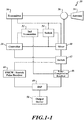
- FIGURE 1-1 shows a block diagram of an exemplary system 30 formed in accordance with an embodiment of the present invention.
- the system 30 includes a transmitter 34 (such as that described above), an antenna 36, a controller 38, a mixer 40, a switch 42, an FMCW/stretch pulse receiver 44, a nonlinear or linear frequency modulation (NLFM or LFM) pulse-compression receiver 46, a digital signal processor (DSP) 48, an output device 50, a circulator 56, and, optionally, a second synthesizer 52, and a second switch 54.
- a transmitter 34 such as that described above
- an antenna 36 such as that described above
- a controller 38 such as that described above
- a mixer 40 such as that described above
- a switch 42 such as that described above
- an FMCW/stretch pulse receiver 44 such as that described above
- NLFM or LFM pulse-compression receiver 46 such as that described above
- DSP digital signal processor
- the controller 38 sends control and/or clock signals to the transmitters 34, 52 and the switches 42, 54. Based on the signals from the controller 38, the transmitter 34 outputs linear or nonlinear pulses or an FMCW signal to the antenna 36 via the circulator 56. Signals received by the antenna 36 are sent to the mixer 40 via the circulator 56 to get mixed with either a delayed signal from the transmitter 34 or a signal from the second synthesizer 52, directly or via the switch 54.
- the switch 42 as controlled by the signal(s) from the controller 38, sends the output of the mixer 40 to one of the receivers 44, 46. If the second synthesizer 52 is used, then the second synthesizer 52 sends a signal to the pulse-compression receiver 46.
- the signal sent to the pulse-compression receiver 46 relates to the signal that the second synthesizer 52 sent to the mixer 40.
- the receivers 44, 46 perform analog signal processing on the received signals(s) before performing a digital conversion and sending the digitized signal(s) to the DSP 48.
- the DSP 48 transforms the digital signal to the frequency domain or performs correlation processing, depending upon which receiver 44, 46 performed the preprocessing (see signal from the controller 38).
- the DSP 48 then generates an output that is sent to the output device 50 for presentation.
- the preprocessing and functions performed by DSP 48 are known to those producing separate FMCW or pulse systems.
- FIGURE 1-2 shows exemplary components of the transmitter 34.
- the transmitter 34 includes a synthesizer 60 and a dual-mode transmitter 64.
- the synthesizer 60 receives the signal(s) from the controller 38 to output a base frequency transmitter signal to the dual-mode transmitter 64 and a delay of the base frequency transmitter signal to the mixer 40 or the second switch 54. In some embodiments, the delayed signal is not generated and sent.
- the dual-mode transmitter 64 generates a radar transmission based on the received base frequency transmitter signal and the signal(s) from the controller 38 then sends the radar transmission to the antenna 36 via the circulator 56.
- the synthesizer 60 includes either a DPLL (as described in U.S. Patents Nos. 7,239,266 or 7,161,527 ) or a fractional N synthesizer with built-in LFM (approximate NLFM with LFM segments).
- exemplary fractional N synthesizers include ADF4159 13 GHz fractional N synthesizer with "direct modulation waveform" capability (Analog Devices) or a Hittite self-contained fractional N synthesizer (HMC769LP6CE, 9.05 to 10+ GHz operation).
- the fractional synthesizers implement FMCW mode and are used to generate linear FMCW or LFM pulse compression at a minimum.
- the Non-Linear FM modulation takes the form of a tangent function. It can be approximated with several small linear FM segments that when combined end to end form the required tangent function (or other shape). This approximation only works for relatively long waveforms and in the limit of short pulses only a DDS could create an NLFM waveform.
- the synthesizers can be used to create NLFM radar systems, as well.
- Fractional N synthesizer to generate the needed waveforms can be used only with synthesizers that provide an internal phase frequency detector (PFD) that operates at frequencies equal to or above 110 MHz.
- PFD phase frequency detector
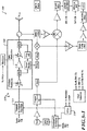
- FIGURES 2-1 and 2-2 show schematic block diagrams of an exemplary system 130 excluding an output device and a controller that performs dual-mode (pulse, FMCW) operation using LFM or NLFM.
- the system 130 can produce signals in the S and X bands.
- the S band is 2.9 - 3.1 GHz.
- the X band is 9.2 to 9.5 GHz.
- the system 130 can output signals to 13 GHz.
- a switch 154 allows a divided (power) and delayed signal associated with the signal outputted by a first synthesizer 160, based on a signal from a controller (i.e., clock (clk) and/or field-programmable gate array (FPGA) such as that produced by Hittite Microwave Corporation) to be sent to a mixer 140.
- the mixer 140 combines the divided and delayed signal with a processed return signal from an antenna 138 via a circulator 156.
- the return signal outputted by the circulator 156 is sent to a receiver-protect device 172, which outputs to a low-noise amplifier (LNA) 174 if the controller has selected the LFM stretch compression mode or outputs to a bypass 176 if FMCW has been selected.
- LNA low-noise amplifier
- the transmitter 164 fires several watts of power can reflect from the antenna 138 and reach the receiver LNA 174 or receiver mixer 140 and destroy them. So a PIN Diode (device 172) is placed in shunt across the receiver input. As soon as a large voltage appears from a transmit pulse the diode conducts and reflects the energy away from the receiver.
- the bypass 176 is controlled by the controller 38 (e.g., FPGA).
- the return signal is based on an FMCW or LFM stretch compression signal outputted by a transmitter 164, according to signals received from the synthesizer 160 and the controller.
- the transmitter 164 includes a variable attenuator 180, a modulator 182, two amplifiers 186, 188, and a low-power filter (LPF) 190.
- the variable attenuator 180 sets the drive level to the transmitter 164 for two modes. In high power mode the attenuator 180 is set to zero so that all of the drive power reaches the amplifier to reach full power. In FMCW mode the transmitter bias levels are reduced substantially and the attenuator 180 is set to a level that will drive the transmitter to 0.1W output level.
- the control signal from the FPGA sets the attenuator as described above.
- the attenuator is used as a fixed load for PLL when the transmitter 164 is pulsed off during stretch LFM mode.
- the attenuator 180 adjusts the drive level for the HPA 186 and 188 in FMCW mode to reduce transmit power to a level preventing self-jamming.
- HPA bias is set for CW operation and much lower voltage levels.
- the attenuator 180 allows for minimum gain/minimum voltage in HPA for proper operation and sets low drive level to provide needed final low-power output.
- the attenuator 180 is also used in a closed-loop configuration with a power detector at the input to the circulator 156 to maintain required fixed output power over temperature and production variation.
- the output of the attenuator 180 is sent to the first amplifier 186 and then to the second amplifier 188, which are both modulated by the modulator 182.
- the modulation causes the components to produce a signal in the desired frequency band.
- the modulator 182 adjusts bias levels to control transmit power of the amplifiers 186, 188.
- the amplifiers 186, 188 are GaN amplifiers.
- the LPF 190 filters the signal outputted from the second amplifier 188 before sending it to the antenna 138 via the circulator 156.
- the transmit power is adjusted as a function of range.
- the power ratio between pulse and CW operation is a maximum of 26 dB.
- a switch 142 sends the output of the mixer 140 to an FMCW/stretch receiver 144.
- the FMCW/stretch receiver 144 performs known analog received-signal preprocessing, converts the processed results to digital then sends the digital signal to a DSP 148.
- the DSP 148 performs a fast-Fourier transform (FFT) on the digitized signal to convert the digitized signal to the frequency domain, based on received antenna angle information (and possible other information, such as a controller signal).
- FFT fast-Fourier transform
- the switch 154 sends an attenuated signal from a second synthesizer 152 to the mixer 140 to mix with the return signal from the LNA 174.
- the switch 142 sends the output of the mixer 140 to a pulse receiver 146, which also receives a signal that is a fraction of the signal generated by the second synthesizer 152.
- the pulse receiver 146 further divides the signal directly received from the second synthesizer 152 and performs I/Q demodulation, based on the signal from the switch 142 and the divided signal.
- NLFM mode a nonlinear waveform is created by the synthesizers 160, 152 using the FPGA to adjust the frequency step rate.
- Chirp bandwidth in pulse mode is set by a clock rate of an analog-to-digital converter in the second receiver 146.
- Chirp bandwidth in FMCW mode sets the range resolution of the radar.
- the IF bandwidth is determined by the chirp bandwidth, the period of the chirp and the maximum range of the radar.
- the Chirp bandwidth is determined by a command to the DDS or Fractional Synthesizer.
- the maximum frequency generated by the synthesizer is less than 1 ⁇ 2 the clock frequency.
- Chirp bandwidth in pulse stretch LFM mode is set by legal bandwidth and IF bandwidth at max range. Legal bandwidth is set by International Treaty for the application.
- Maximum allowed bandwidth in the Marine Radar S Band is 200 MHz and X band.
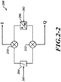
- FIGURE 2-2 shows exemplary components 200 for performing the I/Q demodulation.
- the components 200 include a splitter 204 that splits the return signal 201 received from the switch 142.
- a device 206 splits the signal 202 received from the second synthesizer 152 and phase shifts one of the split signals.
- the outputs from the device 206 and the splitter 204 are sent to combiners 210, 212 for generating I/Q signals.
- the generated I/Q signals are then amplified and digitized before being sent to the DSP 148.
- the DSP 148 performs correlation processing on the digitized I/Q signals in order to detect targets.
- FMCW mode bias of the transmitter 164 is reduced by the modulator 182 for low gain.
- the transmit power is set for ⁇ 20 dBm.
- the transmitter 164 In LFM mode, the transmitter 164 is disabled but the waveform continues as the local oscillator (LO) reference using stretch processing. Because the DPLL is still working after the transmitter stops, a local oscillator signal is supplied to the receiver mixer after the transmitter stops. Stretch processing requires the reference signal to exist during the time signal returns to the receiver. The variable attenuator 180 is set for full power. The second synthesizer/transmitter 152 is not needed as is the same for the FMCW mode.
- LO local oscillator
- the DSP 148 provides ranging and compression similar to that performed by Honeywell's RDR-4000.
- the DSP 148 In the LFM pulse mode, the DSP 148 provides ranging and compression.
- the second synthesizer/transmitter 152 provides a fixed frequency local oscillator signal to permit reception.
- the DSP 148 provides ranging and pulse-to-pulse integration.
- FSK is used for interference mitigation or improved range resolution (pulse-to-pulse frequency step approximation to LFM).
- FIGURE 3 shows a system 230 that operates in NLFM or LFM pulse-compression modes, but not in FMCW or stretch pulse-compression modes.
- the system 230 includes all the same components as the system 130 ( FIGURE 2-1 ) except the system 230 does not include the FMCW/stretch receiver 144, the first or second switch 142, 154 and the bypass 176.
- the system 230 includes a synthesizer 160-1 that does not include a power divider or delay device.
- FIGURE 4 shows a system 280 that operates only in the FMCW or stretch pulse-compression modes.
- the system 280 does not include the second synthesizer 152, the switches 142, 154, the bypass 176, or the pulse receiver 146.
- the FPGA receives a signal from the DSP.
- a direct digital synthesizer is used when the DPLL is used, instead of the fractional synthesizer.
- An exemplary DDS-driven DPLL is described in U.S. Patent Applications Ser. Nos. 12/256,392, filed October 22, 2008 ; and 13/011,771, filed January 21, 2011 .
- the dual-mode transmitter 64 comprises a hybrid coupler configured to control operation of a pulse transmitter component and a lower power FMCW/stretch pulse transmitter component.
- a hybrid coupler configured to control operation of a pulse transmitter component and a lower power FMCW/stretch pulse transmitter component.
- FIGURES 5-1 and 5-2 illustrate a radar system 300 that includes a transmitter 310.
- the transmitter 310 includes a transmit synthesizer 314 that includes a DDS 326 and a fractional N synthesizer 320 that both receive a clock signal from a clock 328 (e.g., 384/128 MHz clock) and control signals from a controller 330 (e.g., FPGA).
- the output of the fractional N synthesizer 320 is filtered by a loop filter 334 before being inputted to a VCO 336 (e.g., 1950.4 or 1990.4 MHz), which sends an output to an amplifier 338.
- the amplified output is sent to a power divider 342 via a coupler 340.
- the coupler 340 returns a portion of the amplified output to the fractional N synthesizer 320.
- a frequency divider 344 divides the output of the power divider 342 by a predefined factor (e.g., 4) to produce an input (e.g., 487.6 - 497.6 MHz) for a first mixer 350.
- the output of the DDS 326 passes through a LPF 354 (e.g., 72-128 MHz) to a second mixer 356 for mixing with the clock signal.
- a BPF 358 filters (e.g., 462-512 MHz) the output of the mixer 356.
- the mixed signal is then amplified by an amplifier 360 before mixing with the frequency divided output at the first mixer 350.
- a BPF 364 filters (e.g., 949.6-1009.6 MHz) the output of the first mixer 350.
- Another mixer 370 mixes an amplified (by an amplifier 366) output of the BPF 364 with the signal (e.g., 1950.4 or 1990.4 MHz) from the power divider 342.
- the output of the mixer 370 is then amplified by an amplifier 372 and then filtered by a BPF 374 (e.g., 2900-3000 MHz).
- the output of the BPF 374 is sent to a transmitter component 380.
- the DDS provides higher performance modulation capability.
- the VCO 336 is an 8-10 GHz VCO made by Hittite and is divided down to 3 GHz by setting the VCO Hittite programmable 1,3 divider to 3, X band sets the divider to 1;
- the coupler 340 is a broadband coupler in order to cover S and X band frequencies.
- the combined S and X band transmitter /synthesizer then becomes a frequency independent module that is common to S and X bands.
- the coupler 340 is a dual-band or broadband design and the driver amplifier 338 is broadband to cover 3/9 GHz.
- the DDS 326 provides high-speed modulation capability and frequency hopping pulse to pulse.
- a low-cost fractional N synthesizer and frequency dividers generate the microwave signal and local oscillator signals (fractional N synthesizer).
- the last two BPFs 364, 374 accommodate the entire transmit bandwidth capability.
- the system 300 allows up to 50 MHz wide chirps and frequency hopping across 100 MHz as long as the shift of the fractional N synthesizer is preplanned, so that it is well settled.
- a system based on a PLL and not a DDS requires time to re-lock after a frequency hop.
- a PLL will unlock if a large step change in frequency is commanded. It will then "ring" and eventually settle to the new commanded frequency - that can take anywhere from many microseconds to milliseconds depending on the frequency step change and the design of the PLL loop gain.
- the synthesizer 314 is required to become part of the S or X band block and not part of the "common" electronics. Only the clock and the DDS would be common to both S and X band systems.
- An exemplary fractional N synthesizer is capable of up to 13 GHz operation. Both X and S have both FMCW and Pulse mode capability.
- the non-common parts are frequency specific - for example the HPA (high power amplifier or transmitter) is a design specific to S band or X band. It is not used for both S and X and would be a design specific to that band with specific GaN transistors.
- the system 314 accommodates 100 MHz of operation across the S or X bands.
- the VCO 336 is commanded to 1950.4 for the first 50 MHz and 1990.4 for the second 50 MHz.
- the 100 MHz band is broken up into a lower and upper band to accommodate frequency limitations. This is done so that the DDS would be used over a frequency range that did not include harmonics.
Landscapes
- Engineering & Computer Science (AREA)
- Radar, Positioning & Navigation (AREA)
- Remote Sensing (AREA)
- Physics & Mathematics (AREA)
- Computer Networks & Wireless Communication (AREA)
- General Physics & Mathematics (AREA)
- Ocean & Marine Engineering (AREA)
- Electromagnetism (AREA)
- Radar Systems Or Details Thereof (AREA)
Applications Claiming Priority (2)
| Application Number | Priority Date | Filing Date | Title |
|---|---|---|---|
| US201261698903P | 2012-09-10 | 2012-09-10 | |
| US13/625,767 US9194946B1 (en) | 2012-09-10 | 2012-09-24 | Combined FMCW and FM pulse-compression radar systems and methods |
Publications (2)
| Publication Number | Publication Date |
|---|---|
| EP2706373A1 EP2706373A1 (en) | 2014-03-12 |
| EP2706373B1 true EP2706373B1 (en) | 2021-02-24 |
Family
ID=49054444
Family Applications (1)
| Application Number | Title | Priority Date | Filing Date |
|---|---|---|---|
| EP13182422.9A Active EP2706373B1 (en) | 2012-09-10 | 2013-08-30 | Combined FMCW and FM pulse-compression radar systems and methods |
Country Status (4)
| Country | Link |
|---|---|
| US (1) | US9194946B1 (enExample) |
| EP (1) | EP2706373B1 (enExample) |
| JP (1) | JP6529712B2 (enExample) |
| CN (1) | CN103675809A (enExample) |
Families Citing this family (38)
| Publication number | Priority date | Publication date | Assignee | Title |
|---|---|---|---|---|
| US20150285897A1 (en) * | 2014-03-31 | 2015-10-08 | Honeywell International Inc. | Hybrid radar system combining fmcw radar and pulsed radar |
| CN104166139A (zh) * | 2014-08-14 | 2014-11-26 | 张家港耐维思通电子科技有限公司 | 一种航海雷达装置 |
| US10114116B2 (en) | 2014-08-19 | 2018-10-30 | Navico Holding As | Common burst for pulse compression radar |
| CN104319492A (zh) * | 2014-09-27 | 2015-01-28 | 史伟立 | 一种Ka波段一维线阵系统 |
| DE102015107419A1 (de) * | 2015-05-12 | 2016-11-17 | HÜBNER GmbH & Co. KG | Radarvorrichtung |
| CN104991230B (zh) * | 2015-06-29 | 2017-06-27 | 中国船舶重工集团公司第七二四研究所 | 基于信号自相关特征的雷达脉冲压缩增益均衡方法 |
| US10324166B2 (en) * | 2015-09-28 | 2019-06-18 | Rockwell Collins, Inc. | Affordable combined pulsed/FMCW radar AESA |
| CN105301592B (zh) * | 2015-10-12 | 2017-09-29 | 合肥工业大学 | 采用汽车防撞雷达系统的多目标识别算法 |
| US10502824B2 (en) * | 2015-11-09 | 2019-12-10 | Infineon Technologies Ag | Frequency modulation scheme for FMCW radar |
| US12185424B2 (en) | 2016-04-20 | 2024-12-31 | Tm Ip Holdings, Llc | Secure routing of data packets including with use with transpositional modulation fortified communications |
| US12133287B1 (en) | 2016-04-20 | 2024-10-29 | Tm Ip Holdings, Llc | Transpositional modulation fortified communications traffic management |
| US9516490B1 (en) | 2016-04-20 | 2016-12-06 | Tm Ip Holdings, Llc | Identifying devices with transpositional modulation |
| CN106597448B (zh) * | 2016-12-14 | 2019-03-19 | 中国电子科技集团公司第二十研究所 | 一种基于双体制发射机的船舶导航雷达 |
| US10830873B2 (en) | 2017-01-06 | 2020-11-10 | Honeywell International Inc. | Synthesizer for radar sensing |
| EP3376255B1 (en) * | 2017-03-14 | 2021-11-17 | Nxp B.V. | Reconfigurable radar unit, integrated circuit and method therefor |
| CN106970372B (zh) * | 2017-05-03 | 2019-08-20 | 四川九洲防控科技有限责任公司 | 一种测量目标对象距离的方法及装置 |
| US10341161B2 (en) | 2017-07-10 | 2019-07-02 | Tm Ip Holdings, Llc | Multi-dimensional signal encoding |
| US10630249B2 (en) * | 2017-08-04 | 2020-04-21 | Texas Instruments Incorporated | Low power mode of operation for mm-wave radar |
| US11460550B2 (en) * | 2017-09-19 | 2022-10-04 | Veoneer Us, Llc | Direct detection LiDAR system and method with synthetic doppler processing |
| JP2019056670A (ja) * | 2017-09-22 | 2019-04-11 | ミツミ電機株式会社 | レーダー装置 |
| CN107861116B (zh) * | 2017-10-31 | 2021-05-25 | 西安电子科技大学 | 一种雷达测距的优化方法 |
| US11112497B2 (en) * | 2018-05-11 | 2021-09-07 | GM Global Technology Operations LLC | Maximum doppler extension via recursive chirp decimation |
| US10594539B2 (en) | 2018-06-05 | 2020-03-17 | Tm Ip Holdings, Llc | Transpositional modulation and demodulation |
| KR102169816B1 (ko) * | 2018-09-12 | 2020-10-26 | 한국과학기술원 | 저잡음 레이더 신호원을 제공하는 방법 및 장치 |
| US10725175B2 (en) | 2018-10-30 | 2020-07-28 | United States Of America As Represented By The Secretary Of The Air Force | Method, apparatus and system for receiving waveform-diverse signals |
| WO2020183392A1 (en) | 2019-03-12 | 2020-09-17 | Uhnder, Inc. | Method and apparatus for mitigation of low frequency noise in radar systems |
| US11614530B2 (en) | 2019-04-15 | 2023-03-28 | American University Of Sharjah | Miniaturized digital radar system |
| CN110784215B (zh) * | 2019-11-27 | 2023-04-07 | 成都赛英科技有限公司 | 基于锁相环产生中心频率可变高速线性调频信号的系统 |
| CN110995260A (zh) * | 2019-12-17 | 2020-04-10 | 陕西长岭电子科技有限责任公司 | 基于线性调频信号的频偏误差控制系统 |
| US11899126B2 (en) * | 2020-01-13 | 2024-02-13 | Uhnder, Inc. | Method and system for multi-chip operation of radar systems |
| KR102311476B1 (ko) * | 2020-02-06 | 2021-10-08 | 한국항공대학교산학협력단 | 다중 모드 레이다에 탑재되는 송수신기 및 이를 포함하는 다중 모드 레이다 |
| US11774583B2 (en) * | 2021-02-26 | 2023-10-03 | Waymo Llc | Methods and systems for filtering vehicle self-reflections in radar |
| US12111390B2 (en) | 2021-07-07 | 2024-10-08 | The Boeing Company | Dual pulsed mode FMCW radar retrofit conversion with adaptive sweep configuration |
| US12230857B2 (en) | 2021-11-30 | 2025-02-18 | Navico, Inc. | Radar waveguide and choke assembly |
| US11936436B2 (en) * | 2021-12-10 | 2024-03-19 | Rohde & Schwarz Gmbh & Co. Kg | External frontend device and frontend system |
| US12044773B2 (en) | 2022-01-06 | 2024-07-23 | The Boeing Company | Multimode electronically steerable monopulse radar |
| US12366655B2 (en) * | 2022-05-17 | 2025-07-22 | Rockwell Collins, Inc. | Reprogrammable radar system and method |
| US12270934B2 (en) * | 2022-10-06 | 2025-04-08 | Furuno Electric Co., Ltd. | Transceiver system of pulse signal and method |
Citations (2)
| Publication number | Priority date | Publication date | Assignee | Title |
|---|---|---|---|---|
| US20050285773A1 (en) * | 2002-06-06 | 2005-12-29 | Roadeye Flr General Partnership | Forward-looking radar system |
| US20080284641A1 (en) * | 2005-11-21 | 2008-11-20 | Plextek Limited | Doppler radar systems |
Family Cites Families (50)
| Publication number | Priority date | Publication date | Assignee | Title |
|---|---|---|---|---|
| US2836811A (en) | 1951-01-18 | 1958-05-27 | Gen Electric | Radar system for detecting object movement and velocity |
| US2941200A (en) | 1953-07-28 | 1960-06-14 | Bell Telephone Labor Inc | Frequency modulated pulse radar |
| US3188637A (en) | 1959-07-07 | 1965-06-08 | Marconi Co Ltd | Fm pulsed radar with intrapulse range discrimination |
| FR1604953A (enExample) | 1960-08-20 | 1972-06-26 | ||
| US3140489A (en) | 1961-10-12 | 1964-07-07 | Gen Electric | Frequency modulated pulse radar system |
| FR1304656A (fr) | 1962-06-05 | 1962-09-28 | Marconi Wireless Telegraph Co | Perfectionnements aux systèmes de radar à impulsions |
| US3390391A (en) | 1965-11-05 | 1968-06-25 | Philips Corp | Radar system employing variable frequency pulses |
| US3382497A (en) | 1966-10-13 | 1968-05-07 | Conductron Corp | Linear frequency modulated radar |
| US3688313A (en) * | 1966-12-19 | 1972-08-29 | Motorola Inc | Combined cw and pulse tracking systems |
| US3383686A (en) | 1967-01-30 | 1968-05-14 | Navy Usa | Diverse frequency echo detection system with doppler frequency coherence |
| US4309703A (en) | 1979-12-28 | 1982-01-05 | International Business Machines Corporation | Segmented chirp waveform implemented radar system |
| US4965533A (en) * | 1989-08-31 | 1990-10-23 | Qualcomm, Inc. | Direct digital synthesizer driven phase lock loop frequency synthesizer |
| US5130714A (en) * | 1991-05-23 | 1992-07-14 | Hughes Aircraft Company | Stretch and chirp waveform format for reduced generating and receiving hardware complexity |
| US5539410A (en) | 1992-03-02 | 1996-07-23 | Motorola, Inc. | Pulse doppler proximity sensor |
| FR2754604B1 (fr) * | 1992-06-05 | 1999-04-09 | Thomson Csf | Dispositif de linearisation d'une rampe de modulation de frequence et son application a un radio-altimetre |
| US5495202A (en) * | 1993-06-30 | 1996-02-27 | Hughes Aircraft Company | High spectral purity digital waveform synthesizer |
| JP3294726B2 (ja) | 1994-12-20 | 2002-06-24 | 本田技研工業株式会社 | レーダ装置 |
| JP3746370B2 (ja) * | 1998-03-13 | 2006-02-15 | スタンレー電気株式会社 | レーダ送受信機 |
| DE19813604A1 (de) | 1998-03-27 | 1999-09-30 | Daimler Benz Aerospace Ag | Anordnung zur präzisen Entfernungsmessung, insbesondere zur Füllstandsmessung |
| US6426717B1 (en) * | 2001-05-11 | 2002-07-30 | Rockwell Collins, Inc. | Single antenna FM radio altimeter operating in a continuous wave mode and an interrupted continuous wave mode |
| US6798374B1 (en) | 2002-11-05 | 2004-09-28 | Decatur Electronics Inc. | Traffic surveillance radar using ranging for accurate target identification |
| US7463710B2 (en) * | 2003-06-27 | 2008-12-09 | Analog Devices, Inc. | Fractional-N synthesizer and method of programming the output phase |
| DE102004015648A1 (de) | 2004-03-31 | 2005-10-27 | Eads Deutschland Gmbh | Linear frequenzmoduliertes Impulsradar |
| TR201905416T4 (tr) * | 2004-04-05 | 2019-05-21 | Weibel Scient A/S | Bir nesnenin radar tarafından tespit edilmesi için sistem ve yöntem. |
| JP4551145B2 (ja) * | 2004-07-13 | 2010-09-22 | 富士通株式会社 | レーダ装置、レーダ装置の制御方法 |
| JP4485285B2 (ja) | 2004-08-12 | 2010-06-16 | 東京レーダー株式会社 | 移動速度測定方法及び移動速度測定方式 |
| US7239266B2 (en) * | 2004-08-26 | 2007-07-03 | Honeywell International Inc. | Radar altimeter |
| US7161527B2 (en) | 2004-09-03 | 2007-01-09 | Honeywell International Inc. | Navigation system |
| GB0506209D0 (en) * | 2005-03-29 | 2005-05-04 | Qinetiq Ltd | Coherent frequency modulated continuous wave radar |
| US7250823B2 (en) * | 2005-05-25 | 2007-07-31 | Harris Corporation | Direct digital synthesis (DDS) phase locked loop (PLL) frequency synthesizer and associated methods |
| EP1777549B1 (en) | 2005-10-24 | 2012-10-03 | Mitsubishi Electric Information Technology Centre Europe B.V. | Object ranging |
| US7616148B2 (en) | 2005-11-23 | 2009-11-10 | Honeywell International Inc. | Microwave smart motion sensor for security applications |
| US7170440B1 (en) * | 2005-12-10 | 2007-01-30 | Landray Technology, Inc. | Linear FM radar |
| US7791530B2 (en) * | 2006-01-05 | 2010-09-07 | Autoliv Asp, Inc. | Time duplex apparatus and method for radar sensor front-ends |
| JP4784332B2 (ja) * | 2006-02-21 | 2011-10-05 | 三菱電機株式会社 | パルスレーダ装置 |
| GB0701812D0 (en) * | 2007-01-31 | 2007-03-14 | Qinetiq Ltd | Antenna system and radar system incorporating the same |
| JP4302746B2 (ja) | 2007-03-01 | 2009-07-29 | 古河電気工業株式会社 | 複合モードレーダ装置 |
| US7791415B2 (en) * | 2007-05-18 | 2010-09-07 | Semtech Corporation | Fractional-N synthesized chirp generator |
| US8384449B2 (en) * | 2008-02-12 | 2013-02-26 | Panasonic Corporation | Synthesizer and reception device using the same |
| US8085097B2 (en) * | 2008-05-06 | 2011-12-27 | Hittite Microwave Corporation | Integrated ramp, sweep fractional frequency synthesizer on an integrated circuit chip |
| US7737880B2 (en) * | 2008-10-22 | 2010-06-15 | Honeywell International Inc. | Microwave and millimeterwave radar sensors |
| US8654006B2 (en) * | 2009-02-13 | 2014-02-18 | Freescale Semiconductor, Inc. | Integrated circuit comprising frequency generation circuitry for controlling a frequency source |
| US8098193B2 (en) * | 2009-11-05 | 2012-01-17 | Honeywell International Inc. | Digitally controlled UWB millimeter wave radar |
| US8633851B2 (en) | 2010-02-19 | 2014-01-21 | Honeywell International Inc. | Low power, space combined, phased array radar |
| US8581778B2 (en) * | 2010-07-19 | 2013-11-12 | Scidea Research, Inc. | Pulse compression system and method |
| US8638139B2 (en) * | 2010-09-10 | 2014-01-28 | Analog Devices, Inc. | Phase locked loop (PLL) based frequency sweep generator |
| US20120112806A1 (en) * | 2010-11-09 | 2012-05-10 | Sony Corporation | Frequency synthesizer and frequency synthesizing method |
| US8476945B2 (en) * | 2011-03-23 | 2013-07-02 | International Business Machines Corporation | Phase profile generator |
| US8866667B2 (en) * | 2012-02-22 | 2014-10-21 | Honeywell International Inc. | High sensitivity single antenna FMCW radar |
| US9081094B2 (en) * | 2012-02-22 | 2015-07-14 | Honeywell International Inc. | Aircraft radar altimeter structure |
-
2012
- 2012-09-24 US US13/625,767 patent/US9194946B1/en active Active
-
2013
- 2013-08-30 EP EP13182422.9A patent/EP2706373B1/en active Active
- 2013-09-06 JP JP2013184656A patent/JP6529712B2/ja active Active
- 2013-09-09 CN CN201310472406.5A patent/CN103675809A/zh active Pending
Patent Citations (2)
| Publication number | Priority date | Publication date | Assignee | Title |
|---|---|---|---|---|
| US20050285773A1 (en) * | 2002-06-06 | 2005-12-29 | Roadeye Flr General Partnership | Forward-looking radar system |
| US20080284641A1 (en) * | 2005-11-21 | 2008-11-20 | Plextek Limited | Doppler radar systems |
Non-Patent Citations (1)
| Title |
|---|
| "RADAR TECHNOLOGY ENCYCLOPEDIA.", 1 January 1998, BOSTON, MA : ARTECH HOUSE., US, ISBN: 978-0-89006-893-9, article DAVID K BARTON: "Pulse Compression", pages: 315 - 318, XP055666964 * |
Also Published As
| Publication number | Publication date |
|---|---|
| CN103675809A (zh) | 2014-03-26 |
| US9194946B1 (en) | 2015-11-24 |
| EP2706373A1 (en) | 2014-03-12 |
| JP2014095689A (ja) | 2014-05-22 |
| JP6529712B2 (ja) | 2019-06-12 |
Similar Documents
| Publication | Publication Date | Title |
|---|---|---|
| EP2706373B1 (en) | Combined FMCW and FM pulse-compression radar systems and methods | |
| JP2014095689A5 (enExample) | ||
| EP2180336B1 (en) | Microwave and millimeterwave radar sensors | |
| EP2127066B1 (en) | Radar having a low noise frequency generator | |
| EP2798369B1 (en) | Radar system providing multiple waveforms for long range and short range target detection | |
| JP3021160B2 (ja) | パルスドップラーレーダの送受信部 | |
| US6426717B1 (en) | Single antenna FM radio altimeter operating in a continuous wave mode and an interrupted continuous wave mode | |
| RU2451373C1 (ru) | Активная фазированная антенная решетка | |
| US4360812A (en) | FM-CW Fuze | |
| US20170285135A1 (en) | High probability of intercept radar detector | |
| KR101355537B1 (ko) | Gmti 모드와 sar 모드를 위한 광대역 송수신 시스템 및 방법 | |
| KR101908490B1 (ko) | 누설 신호를 감소시킬 수 있는 w 대역 레이더 장치 | |
| US7880665B1 (en) | System and method for adaptation of a radar receiver in response to frequency drift in a transmission source | |
| CN104062637A (zh) | 无人机巡线避障雷达宽带线性调频连续毫米波信号发射源 | |
| US20080246650A1 (en) | Short Range Radar and Method of Controlling the Same | |
| CN110632583A (zh) | 一种数字无线电高度表 | |
| KR102313317B1 (ko) | 다수의 피엘엘을 이용한 에프엠씨더불유 레이다 송수신 장치 | |
| Waldmann et al. | Pulsed frequency modulation techniques for high-precision ultra wideband ranging and positioning | |
| Faghih-Naini et al. | Design and evaluation of a joint communication and sensing system using FMCW-radar and FSK in V-band | |
| CN113253208A (zh) | 基于傅里叶锁模光电振荡器的步进频雷达 | |
| Ghelfi et al. | Fully photonics-based radar demonstrator: concept and field trials | |
| Onori et al. | A software-defined and filter-free 0–26.5 GHz ultra-wideband RF transmitter enabled by photonics | |
| KR20180117788A (ko) | 고주파 신호의 송/수신 시간을 조절하는 방법 및 그 장치 | |
| WO2023068970A1 (ru) | Приёмо-передающее устройство гомодинного радиолокатора | |
| RU94091U1 (ru) | Синтезаторный приемоответчик миллиметрового диапазона волн |
Legal Events
| Date | Code | Title | Description |
|---|---|---|---|
| PUAI | Public reference made under article 153(3) epc to a published international application that has entered the european phase |
Free format text: ORIGINAL CODE: 0009012 |
|
| 17P | Request for examination filed |
Effective date: 20130830 |
|
| AK | Designated contracting states |
Kind code of ref document: A1 Designated state(s): AL AT BE BG CH CY CZ DE DK EE ES FI FR GB GR HR HU IE IS IT LI LT LU LV MC MK MT NL NO PL PT RO RS SE SI SK SM TR |
|
| AX | Request for extension of the european patent |
Extension state: BA ME |
|
| RAP1 | Party data changed (applicant data changed or rights of an application transferred) |
Owner name: HONEYWELL INTERNATIONAL INC. |
|
| STAA | Information on the status of an ep patent application or granted ep patent |
Free format text: STATUS: EXAMINATION IS IN PROGRESS |
|
| GRAP | Despatch of communication of intention to grant a patent |
Free format text: ORIGINAL CODE: EPIDOSNIGR1 |
|
| STAA | Information on the status of an ep patent application or granted ep patent |
Free format text: STATUS: GRANT OF PATENT IS INTENDED |
|
| INTG | Intention to grant announced |
Effective date: 20201013 |
|
| GRAS | Grant fee paid |
Free format text: ORIGINAL CODE: EPIDOSNIGR3 |
|
| GRAA | (expected) grant |
Free format text: ORIGINAL CODE: 0009210 |
|
| STAA | Information on the status of an ep patent application or granted ep patent |
Free format text: STATUS: THE PATENT HAS BEEN GRANTED |
|
| AK | Designated contracting states |
Kind code of ref document: B1 Designated state(s): AL AT BE BG CH CY CZ DE DK EE ES FI FR GB GR HR HU IE IS IT LI LT LU LV MC MK MT NL NO PL PT RO RS SE SI SK SM TR |
|
| REG | Reference to a national code |
Ref country code: GB Ref legal event code: FG4D |
|
| REG | Reference to a national code |
Ref country code: CH Ref legal event code: EP |
|
| REG | Reference to a national code |
Ref country code: AT Ref legal event code: REF Ref document number: 1365176 Country of ref document: AT Kind code of ref document: T Effective date: 20210315 |
|
| REG | Reference to a national code |
Ref country code: IE Ref legal event code: FG4D |
|
| REG | Reference to a national code |
Ref country code: DE Ref legal event code: R096 Ref document number: 602013075820 Country of ref document: DE |
|
| REG | Reference to a national code |
Ref country code: NL Ref legal event code: FP |
|
| REG | Reference to a national code |
Ref country code: SE Ref legal event code: TRGR |
|
| REG | Reference to a national code |
Ref country code: LT Ref legal event code: MG9D |
|
| PG25 | Lapsed in a contracting state [announced via postgrant information from national office to epo] |
Ref country code: PT Free format text: LAPSE BECAUSE OF FAILURE TO SUBMIT A TRANSLATION OF THE DESCRIPTION OR TO PAY THE FEE WITHIN THE PRESCRIBED TIME-LIMIT Effective date: 20210624 Ref country code: LT Free format text: LAPSE BECAUSE OF FAILURE TO SUBMIT A TRANSLATION OF THE DESCRIPTION OR TO PAY THE FEE WITHIN THE PRESCRIBED TIME-LIMIT Effective date: 20210224 Ref country code: FI Free format text: LAPSE BECAUSE OF FAILURE TO SUBMIT A TRANSLATION OF THE DESCRIPTION OR TO PAY THE FEE WITHIN THE PRESCRIBED TIME-LIMIT Effective date: 20210224 Ref country code: HR Free format text: LAPSE BECAUSE OF FAILURE TO SUBMIT A TRANSLATION OF THE DESCRIPTION OR TO PAY THE FEE WITHIN THE PRESCRIBED TIME-LIMIT Effective date: 20210224 Ref country code: GR Free format text: LAPSE BECAUSE OF FAILURE TO SUBMIT A TRANSLATION OF THE DESCRIPTION OR TO PAY THE FEE WITHIN THE PRESCRIBED TIME-LIMIT Effective date: 20210525 Ref country code: BG Free format text: LAPSE BECAUSE OF FAILURE TO SUBMIT A TRANSLATION OF THE DESCRIPTION OR TO PAY THE FEE WITHIN THE PRESCRIBED TIME-LIMIT Effective date: 20210524 Ref country code: NO Free format text: LAPSE BECAUSE OF FAILURE TO SUBMIT A TRANSLATION OF THE DESCRIPTION OR TO PAY THE FEE WITHIN THE PRESCRIBED TIME-LIMIT Effective date: 20210524 |
|
| REG | Reference to a national code |
Ref country code: AT Ref legal event code: MK05 Ref document number: 1365176 Country of ref document: AT Kind code of ref document: T Effective date: 20210224 |
|
| PG25 | Lapsed in a contracting state [announced via postgrant information from national office to epo] |
Ref country code: LV Free format text: LAPSE BECAUSE OF FAILURE TO SUBMIT A TRANSLATION OF THE DESCRIPTION OR TO PAY THE FEE WITHIN THE PRESCRIBED TIME-LIMIT Effective date: 20210224 Ref country code: PL Free format text: LAPSE BECAUSE OF FAILURE TO SUBMIT A TRANSLATION OF THE DESCRIPTION OR TO PAY THE FEE WITHIN THE PRESCRIBED TIME-LIMIT Effective date: 20210224 Ref country code: RS Free format text: LAPSE BECAUSE OF FAILURE TO SUBMIT A TRANSLATION OF THE DESCRIPTION OR TO PAY THE FEE WITHIN THE PRESCRIBED TIME-LIMIT Effective date: 20210224 |
|
| PG25 | Lapsed in a contracting state [announced via postgrant information from national office to epo] |
Ref country code: IS Free format text: LAPSE BECAUSE OF FAILURE TO SUBMIT A TRANSLATION OF THE DESCRIPTION OR TO PAY THE FEE WITHIN THE PRESCRIBED TIME-LIMIT Effective date: 20210624 |
|
| PG25 | Lapsed in a contracting state [announced via postgrant information from national office to epo] |
Ref country code: AT Free format text: LAPSE BECAUSE OF FAILURE TO SUBMIT A TRANSLATION OF THE DESCRIPTION OR TO PAY THE FEE WITHIN THE PRESCRIBED TIME-LIMIT Effective date: 20210224 Ref country code: SM Free format text: LAPSE BECAUSE OF FAILURE TO SUBMIT A TRANSLATION OF THE DESCRIPTION OR TO PAY THE FEE WITHIN THE PRESCRIBED TIME-LIMIT Effective date: 20210224 Ref country code: CZ Free format text: LAPSE BECAUSE OF FAILURE TO SUBMIT A TRANSLATION OF THE DESCRIPTION OR TO PAY THE FEE WITHIN THE PRESCRIBED TIME-LIMIT Effective date: 20210224 Ref country code: EE Free format text: LAPSE BECAUSE OF FAILURE TO SUBMIT A TRANSLATION OF THE DESCRIPTION OR TO PAY THE FEE WITHIN THE PRESCRIBED TIME-LIMIT Effective date: 20210224 |
|
| REG | Reference to a national code |
Ref country code: DE Ref legal event code: R097 Ref document number: 602013075820 Country of ref document: DE |
|
| PG25 | Lapsed in a contracting state [announced via postgrant information from national office to epo] |
Ref country code: RO Free format text: LAPSE BECAUSE OF FAILURE TO SUBMIT A TRANSLATION OF THE DESCRIPTION OR TO PAY THE FEE WITHIN THE PRESCRIBED TIME-LIMIT Effective date: 20210224 Ref country code: DK Free format text: LAPSE BECAUSE OF FAILURE TO SUBMIT A TRANSLATION OF THE DESCRIPTION OR TO PAY THE FEE WITHIN THE PRESCRIBED TIME-LIMIT Effective date: 20210224 Ref country code: ES Free format text: LAPSE BECAUSE OF FAILURE TO SUBMIT A TRANSLATION OF THE DESCRIPTION OR TO PAY THE FEE WITHIN THE PRESCRIBED TIME-LIMIT Effective date: 20210224 Ref country code: SK Free format text: LAPSE BECAUSE OF FAILURE TO SUBMIT A TRANSLATION OF THE DESCRIPTION OR TO PAY THE FEE WITHIN THE PRESCRIBED TIME-LIMIT Effective date: 20210224 |
|
| PLBE | No opposition filed within time limit |
Free format text: ORIGINAL CODE: 0009261 |
|
| STAA | Information on the status of an ep patent application or granted ep patent |
Free format text: STATUS: NO OPPOSITION FILED WITHIN TIME LIMIT |
|
| PG25 | Lapsed in a contracting state [announced via postgrant information from national office to epo] |
Ref country code: AL Free format text: LAPSE BECAUSE OF FAILURE TO SUBMIT A TRANSLATION OF THE DESCRIPTION OR TO PAY THE FEE WITHIN THE PRESCRIBED TIME-LIMIT Effective date: 20210224 |
|
| 26N | No opposition filed |
Effective date: 20211125 |
|
| PG25 | Lapsed in a contracting state [announced via postgrant information from national office to epo] |
Ref country code: SI Free format text: LAPSE BECAUSE OF FAILURE TO SUBMIT A TRANSLATION OF THE DESCRIPTION OR TO PAY THE FEE WITHIN THE PRESCRIBED TIME-LIMIT Effective date: 20210224 |
|
| REG | Reference to a national code |
Ref country code: CH Ref legal event code: PL |
|
| PG25 | Lapsed in a contracting state [announced via postgrant information from national office to epo] |
Ref country code: MC Free format text: LAPSE BECAUSE OF FAILURE TO SUBMIT A TRANSLATION OF THE DESCRIPTION OR TO PAY THE FEE WITHIN THE PRESCRIBED TIME-LIMIT Effective date: 20210224 |
|
| REG | Reference to a national code |
Ref country code: BE Ref legal event code: MM Effective date: 20210831 |
|
| PG25 | Lapsed in a contracting state [announced via postgrant information from national office to epo] |
Ref country code: LI Free format text: LAPSE BECAUSE OF NON-PAYMENT OF DUE FEES Effective date: 20210831 Ref country code: CH Free format text: LAPSE BECAUSE OF NON-PAYMENT OF DUE FEES Effective date: 20210831 |
|
| PG25 | Lapsed in a contracting state [announced via postgrant information from national office to epo] |
Ref country code: IS Free format text: LAPSE BECAUSE OF FAILURE TO SUBMIT A TRANSLATION OF THE DESCRIPTION OR TO PAY THE FEE WITHIN THE PRESCRIBED TIME-LIMIT Effective date: 20210624 Ref country code: LU Free format text: LAPSE BECAUSE OF NON-PAYMENT OF DUE FEES Effective date: 20210830 |
|
| PG25 | Lapsed in a contracting state [announced via postgrant information from national office to epo] |
Ref country code: IE Free format text: LAPSE BECAUSE OF NON-PAYMENT OF DUE FEES Effective date: 20210830 Ref country code: BE Free format text: LAPSE BECAUSE OF NON-PAYMENT OF DUE FEES Effective date: 20210831 |
|
| PGFP | Annual fee paid to national office [announced via postgrant information from national office to epo] |
Ref country code: NL Payment date: 20220823 Year of fee payment: 10 |
|
| PGFP | Annual fee paid to national office [announced via postgrant information from national office to epo] |
Ref country code: SE Payment date: 20220823 Year of fee payment: 10 Ref country code: GB Payment date: 20220823 Year of fee payment: 10 |
|
| PG25 | Lapsed in a contracting state [announced via postgrant information from national office to epo] |
Ref country code: HU Free format text: LAPSE BECAUSE OF FAILURE TO SUBMIT A TRANSLATION OF THE DESCRIPTION OR TO PAY THE FEE WITHIN THE PRESCRIBED TIME-LIMIT; INVALID AB INITIO Effective date: 20130830 |
|
| PG25 | Lapsed in a contracting state [announced via postgrant information from national office to epo] |
Ref country code: CY Free format text: LAPSE BECAUSE OF FAILURE TO SUBMIT A TRANSLATION OF THE DESCRIPTION OR TO PAY THE FEE WITHIN THE PRESCRIBED TIME-LIMIT Effective date: 20210224 |
|
| P01 | Opt-out of the competence of the unified patent court (upc) registered |
Effective date: 20230525 |
|
| REG | Reference to a national code |
Ref country code: NL Ref legal event code: MM Effective date: 20230901 |
|
| GBPC | Gb: european patent ceased through non-payment of renewal fee |
Effective date: 20230830 |
|
| PG25 | Lapsed in a contracting state [announced via postgrant information from national office to epo] |
Ref country code: MK Free format text: LAPSE BECAUSE OF FAILURE TO SUBMIT A TRANSLATION OF THE DESCRIPTION OR TO PAY THE FEE WITHIN THE PRESCRIBED TIME-LIMIT Effective date: 20210224 |
|
| PG25 | Lapsed in a contracting state [announced via postgrant information from national office to epo] |
Ref country code: NL Free format text: LAPSE BECAUSE OF NON-PAYMENT OF DUE FEES Effective date: 20230901 |
|
| PG25 | Lapsed in a contracting state [announced via postgrant information from national office to epo] |
Ref country code: SE Free format text: LAPSE BECAUSE OF NON-PAYMENT OF DUE FEES Effective date: 20230831 Ref country code: NL Free format text: LAPSE BECAUSE OF NON-PAYMENT OF DUE FEES Effective date: 20230901 |
|
| PG25 | Lapsed in a contracting state [announced via postgrant information from national office to epo] |
Ref country code: GB Free format text: LAPSE BECAUSE OF NON-PAYMENT OF DUE FEES Effective date: 20230830 |
|
| PG25 | Lapsed in a contracting state [announced via postgrant information from national office to epo] |
Ref country code: GB Free format text: LAPSE BECAUSE OF NON-PAYMENT OF DUE FEES Effective date: 20230830 |
|
| PG25 | Lapsed in a contracting state [announced via postgrant information from national office to epo] |
Ref country code: MT Free format text: LAPSE BECAUSE OF FAILURE TO SUBMIT A TRANSLATION OF THE DESCRIPTION OR TO PAY THE FEE WITHIN THE PRESCRIBED TIME-LIMIT Effective date: 20210224 |
|
| PGFP | Annual fee paid to national office [announced via postgrant information from national office to epo] |
Ref country code: DE Payment date: 20250827 Year of fee payment: 13 |
|
| PGFP | Annual fee paid to national office [announced via postgrant information from national office to epo] |
Ref country code: IT Payment date: 20250825 Year of fee payment: 13 |
|
| PGFP | Annual fee paid to national office [announced via postgrant information from national office to epo] |
Ref country code: FR Payment date: 20250825 Year of fee payment: 13 |
|
| PG25 | Lapsed in a contracting state [announced via postgrant information from national office to epo] |
Ref country code: TR Free format text: LAPSE BECAUSE OF FAILURE TO SUBMIT A TRANSLATION OF THE DESCRIPTION OR TO PAY THE FEE WITHIN THE PRESCRIBED TIME-LIMIT Effective date: 20210224 |