EP2706277A2 - Rohrschraube zur Befestigung einer Rohrleitung und ein Verfahren zur Herstellung einer solchen Rohrschraube - Google Patents
Rohrschraube zur Befestigung einer Rohrleitung und ein Verfahren zur Herstellung einer solchen Rohrschraube Download PDFInfo
- Publication number
- EP2706277A2 EP2706277A2 EP20130183804 EP13183804A EP2706277A2 EP 2706277 A2 EP2706277 A2 EP 2706277A2 EP 20130183804 EP20130183804 EP 20130183804 EP 13183804 A EP13183804 A EP 13183804A EP 2706277 A2 EP2706277 A2 EP 2706277A2
- Authority
- EP
- European Patent Office
- Prior art keywords
- layer
- pipe screw
- friction
- pipe
- threaded portion
- Prior art date
- Legal status (The legal status is an assumption and is not a legal conclusion. Google has not performed a legal analysis and makes no representation as to the accuracy of the status listed.)
- Granted
Links
Images
Classifications
-
- F—MECHANICAL ENGINEERING; LIGHTING; HEATING; WEAPONS; BLASTING
- F16—ENGINEERING ELEMENTS AND UNITS; GENERAL MEASURES FOR PRODUCING AND MAINTAINING EFFECTIVE FUNCTIONING OF MACHINES OR INSTALLATIONS; THERMAL INSULATION IN GENERAL
- F16L—PIPES; JOINTS OR FITTINGS FOR PIPES; SUPPORTS FOR PIPES, CABLES OR PROTECTIVE TUBING; MEANS FOR THERMAL INSULATION IN GENERAL
- F16L19/00—Joints in which sealing surfaces are pressed together by means of a member, e.g. a swivel nut, screwed on, or into, one of the joint parts
- F16L19/02—Pipe ends provided with collars or flanges, integral with the pipe or not, pressed together by a screwed member
- F16L19/025—Pipe ends provided with collars or flanges, integral with the pipe or not, pressed together by a screwed member the pipe ends having integral collars or flanges
- F16L19/028—Pipe ends provided with collars or flanges, integral with the pipe or not, pressed together by a screwed member the pipe ends having integral collars or flanges the collars or flanges being obtained by deformation of the pipe wall
- F16L19/0286—Pipe ends provided with collars or flanges, integral with the pipe or not, pressed together by a screwed member the pipe ends having integral collars or flanges the collars or flanges being obtained by deformation of the pipe wall and being formed as a flange
-
- B—PERFORMING OPERATIONS; TRANSPORTING
- B60—VEHICLES IN GENERAL
- B60T—VEHICLE BRAKE CONTROL SYSTEMS OR PARTS THEREOF; BRAKE CONTROL SYSTEMS OR PARTS THEREOF, IN GENERAL; ARRANGEMENT OF BRAKING ELEMENTS ON VEHICLES IN GENERAL; PORTABLE DEVICES FOR PREVENTING UNWANTED MOVEMENT OF VEHICLES; VEHICLE MODIFICATIONS TO FACILITATE COOLING OF BRAKES
- B60T17/00—Component parts, details, or accessories of power brake systems not covered by groups B60T8/00, B60T13/00 or B60T15/00, or presenting other characteristic features
- B60T17/04—Arrangements of piping, valves in the piping, e.g. cut-off valves, couplings or air hoses
- B60T17/043—Brake line couplings, air hoses and stopcocks
-
- F—MECHANICAL ENGINEERING; LIGHTING; HEATING; WEAPONS; BLASTING
- F16—ENGINEERING ELEMENTS AND UNITS; GENERAL MEASURES FOR PRODUCING AND MAINTAINING EFFECTIVE FUNCTIONING OF MACHINES OR INSTALLATIONS; THERMAL INSULATION IN GENERAL
- F16L—PIPES; JOINTS OR FITTINGS FOR PIPES; SUPPORTS FOR PIPES, CABLES OR PROTECTIVE TUBING; MEANS FOR THERMAL INSULATION IN GENERAL
- F16L19/00—Joints in which sealing surfaces are pressed together by means of a member, e.g. a swivel nut, screwed on, or into, one of the joint parts
- F16L19/02—Pipe ends provided with collars or flanges, integral with the pipe or not, pressed together by a screwed member
- F16L19/0243—Pipe ends provided with collars or flanges, integral with the pipe or not, pressed together by a screwed member specially adapted for use with coated pipes
Definitions
- the invention relates to a pipe screw for fastening a pipeline. Furthermore, the invention relates to a method for producing such a pipe screw.
- Pipe screws are used to connect a pipeline to an aggregate in a braking system of a motor vehicle.
- Conventional pipe screws have a passage in the axial direction for receiving the pipe and an external thread.
- the pipeline is inserted into the passage such that a pipe arranged on the end side according to the DIN standard standardized flare contacts a bolt collar of the pipe screw. Subsequently, the pipe screw is screwed together with the inserted pipe in an opening of the unit.
- EP 2 136 119 B1 shows a pipe screw having a threaded portion and a thread-free contact surface, wherein the threaded portion and the unthreaded contact surface are each provided with a different friction-reduced coating.
- the disadvantage here is that the coating is relatively hard due to their properties in the cured state, so that it can come in particular in the contact area of the pipe screw to Bördelschulter to a chipping of the sliding coating.
- the production of such a pipe screw is relatively expensive, since different coating materials are used.
- EP 1 411 288 A1 discloses a threaded connection for steel pipes of oil lines.
- the threaded connection comprises a connection and a threaded box, both of which have a contact surface with a threaded region and a threadless contact region.
- the contact area of the terminal or the threaded box is provided with a metallic base layer and a sliding layer applied thereon, wherein the sliding layer may be formed from a solid or liquid sliding layer.
- the invention is therefore an object of the invention to provide a pipe screw of the type mentioned, which has an improved coating and is also inexpensive to manufacture.
- the pipe screw according to the invention has a threaded portion and a collar portion, wherein the threaded portion and the collar portion at least partially provided with a first layer having a friction-reducing layer, and wherein the collar portion at least partially with a second layer having the friction-reducing layer, is provided. Due to the second layer, a sufficient amount of the friction-reducing layer is available, in particular in the contact region. Thus, a torsion of the pipe during screwing is advantageously avoided.
- the friction reducing layer is a lubricant.
- the layer may also be referred to as a coating or coating, wherein the layer may comprise exclusively or inter alia the friction-reducing layer.
- the layer formed from the lubricant is advantageously made soft, so that chipping during the screwing is avoided. Since the second layer and the first layer are formed from the same friction-reducing layers, the fastening element according to the invention is inexpensive to manufacture.
- the collar portion is partially or completely provided with the second layer having the friction-reducing layer.
- the first layer in the region of the threaded section is treated such that the ratio of the coefficient of friction of the first layer in the region of the threaded section to the first and / or second layer is between 1.5 and 3.
- a required friction coefficient in the region of the threaded portion can be adjusted to a screwing required for the connection of pipe with an aggregate of a brake system to reach.
- the coefficient of friction adaptation in the threaded section is achieved by a partial thermal modification of the first layer in the region of the threaded section.
- the coefficient of friction of the first layer after the thermal aftertreatment is between 0.08 and 0.2.
- the friction-reducing layer or the lubricant is a polyethylene-based dry sliding film.
- the polyethylene-based dry sliding film is provided with a synergistic solid lubricant.
- the solid lubricant is a combination of polytetrafluoroethylene with embedded sulfides and silicates.
- the layer comprises 5% to 20% polyethylene, 5% to 60% polytetrafluoroethylene, 5% to 60% embedded sulfides and 3% to 20% silicates.
- the lubricant is water-soluble and forms after drying a thin, gray layer with a definable friction coefficient.
- the coefficient of friction of the friction reducing layer on the thread is between 0.08 and 0.2 and on the screw collar between 0.04 and 0.12.
- a corrosion protection layer is provided between the surface of the pipe screw and the first layer.
- the corrosion protection layer preferably consists of a zinc-nickel coating whose layer thickness is between 8 ⁇ m and 15 ⁇ m. More preferably, the nickel content in the zinc-nickel coating is between 12% and 15%.
- the layer thickness of the first layer is between 1 ⁇ m and 2 ⁇ m.
- the layer thickness of the second layer is preferably between 0.5 ⁇ m and 1.5 ⁇ m.
- the invention relates to a method for producing the pipe screw according to the invention.
- the method comprises the following steps. First, a pipe screw comprising a threaded portion and a collar portion is produced. Subsequently, at least in sections, a first layer, which has a friction-reducing layer, is applied in the region of the threaded section and the collar section. Finally, at least in sections, a second layer, which has the friction-reducing layer, is applied to the first layer in the region of the waistband section.
- the method ensures the production of a pipe screw, which has a reduced friction in the contact area of the pipe and collar portion and at the same time is inexpensive to manufacture.
- a lubricant is used as the friction-reducing layer.
- the friction reducing layer is a polyethylene-based dry sliding film.
- the polyethylene-based dry sliding film is provided with a synergistic solid lubricant.
- the solid lubricant is a combination of polytetrafluoroethylene with embedded sulfides and silicates.
- the layer comprises 5% to 20% polyethylene, 5% to 60% polytetrafluoroethylene, 5% to 60% embedded sulfides and 3% to 20% silicates.
- the lubricant is water soluble and forms after drying a thin, gray layer with a definable friction coefficient.
- the coefficient of friction is the friction-reducing layer on the screw collar between 0.04 and 0.12.
- the pipe screw is produced by means of a cutting and / or non-cutting process. Further preferably, the pipe screw is surface-treated after the production thereof. The surface treatment is preferably carried out by means of an annealing process, wherein the pipe screw over a period of about six hours at about 200 to 230 ° C is heat treated. Preferably, the tube screw is cleaned after annealing in an alkaline ultrasonic bath.
- the surface of the pipe screw is roughened, the surface roughness Ra being between 1.0 ⁇ m and 1.5 ⁇ m.
- the entire pipe screw is treated with a blasting material in one operation. The roughening of the surface improves the adhesion of the subsequently applied layer on the pipe screw.
- a corrosion protection layer is preferably applied, which is chemically activated by means of a low-pressure plasma process.
- the corrosion protection layer is applied by means of an electrolytic galvanizing on the roughened surface of the pipe screw.
- the anticorrosive layer preferably consists of a zinc-nickel coating whose layer thickness is between 8 ⁇ m and 15 ⁇ m. More preferably, the nickel content in the zinc-nickel coating is between 12% and 15%.
- the chemical activation of the corrosion protection layer is advantageously carried out after the application of the corrosion protection layer by a plasma jet for activating the layer, in particular in the region of the threaded portion and in the region of the collar portion, is positioned.
- the plasma treatment is carried out in a pure oxygen negative pressure atmosphere.
- the application of the corrosion protection layer before applying the first layer.
- the first layer is applied by means of a dipping method or drum method.
- the pipe screw is preferably suspended at its head portion and completely immersed in a bath filled with the lubricant.
- the pipe screw is coated in a drum by rotation with the lubricant.
- the tube screw is heated after the application of the first layer.
- the heating takes place in a convection oven at a temperature between 50 ° C and 250 ° C.
- the first layer of the friction-reducing layer is dried on the one hand and crosslinked on the other hand.
- the drying process of the first layer can also be completely or partially carried out during transport to the circulating air oven
- the first layer is thermally post-treated or modified in the region of the threaded section.
- a partial thermal destruction of the friction-reducing layer in the region of the threaded portion is achieved, so that the coefficient of friction in the threaded portion is increased.
- a required for screwing into an aggregate of a braking system minimum friction coefficient is set.
- the coefficient of friction for the thread after the thermal aftertreatment is between 0.08 and 0.2.
- the thermal aftertreatment can take place during heating in a circulating air oven. Furthermore, the thermal aftertreatment can also take place outside of the circulating air oven by means of induction.
- the second layer is applied by means of a pad printing process.
- This is an indirect gravure printing process in which an elastic pad impregnated with the lubricant is pressed onto the waistband section.
- the second layer or the lubricant is applied to the entire collar portion by means of the pad printing process.
- the pipe screw is air-dried.
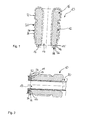
- Fig. 1 is a pipe screw 10 according to the invention, which serves for fastening a pipe 30 to an aggregate of a brake system, not shown, shown.
- the pipe screw 10 has a threaded portion 12, a collar portion 14, a head portion 16 and an axially extending passage 17.
- the head portion 16 is formed in the present embodiment as a hexagon, but may also be designed differently.
- the collar portion 14 is disposed on a head end 16 opposite the front end of the pipe screw 10 and has a straight portion 13 and a conical portion 15.
- the threaded portion 12 is formed as an external thread.
- the surface of the pipe screw 10 is provided with a coating 20 which is shown schematically and enlarged.
- the coating 20 comprises a corrosion protection layer 22, a first one Layer 24, which has a friction-reducing layer 26, and a second layer 28, which has the friction-reducing layer 26.
- the corrosion protection layer 22 is dotted, the first layer 24 dash-dotted lines and the second layer 28 shown in dashed lines.
- the corrosion protection layer 22 is applied to the entire surface of the pipe screw 10 and connected to this materially.
- the first layer 24 is applied and connected to this materially.
- the second layer 28 is applied to the first layer 24 in the region of the collar portion 14 and connected to the first layer 24 cohesively.
- the friction reducing layer 26 is a lubricant comprising a polyethylene-based dry sliding film having a synergistic solid lubricant.
- the solid lubricant may be a combination of polytetrafluoroethylene with embedded sulfides and silicates.
- the layer 26 may consist of 5% to 20% polyethylene, 5% to 60% polytetrafluoroethylene, 5% to 60% embedded sulfides and 3% to 20% silicates.
- the tubular screw 10 it is initially produced by machining or without cutting. Subsequently, the surface of the pipe screw 10 can be tempered by means of an annealing process by the pipe screw 10 is heat treated at about 200 to 230 ° C over a period of about six hours. In the case of a surface treatment, the pipe screw 10 is cleaned in an alkaline ultrasonic bath. This is followed by a mechanical treatment of the surface of the pipe screw 10 by being treated with a blasting material. This produces a surface roughness Ra of between 1 ⁇ m and 1.5 ⁇ m. Subsequently, the application of the corrosion protection layer 22 by means of an electronic galvanizing takes place.
- the corrosion protection layer 22 consists of a zinc-nickel coating, wherein the layer thickness between 8 microns and 15 microns and the nickel content in the zinc-nickel coating can be between 12% and 15%.
- the surface of the pipe screw 10 is chemically activated in a low pressure plasma process by directing a plasma jet to the threaded portion 12 and the collar portion 14. The plasma treatment is carried out in a pure oxygen negative pressure atmosphere. This is followed by the application of the first and second layers 24, 28, which have the friction-reducing layer 26.
- the first layer 24 is applied to the entire surface of the pipe screw 10. This can be done for example in the dipping process.
- the pipe screw 10 is suspended at its head portion 16 and completely immersed in a Gleitsch Anlagen.
- the pipe screw 10 can be provided with the first layer 24 in the drum process.
- the pipe screw 10 is rotated in a drum and thereby provided with the first layer 24.
- the tube screw 10 is heated to dry and crosslink the first layer 24 completely in a circulating air oven at a temperature of 50 ° C to 250 ° C.
- a drying of the first layer 24 even during transport to the circulating oven completely or partially.
- the heating also causes a partial thermal destruction of the first layer 24.
- the coefficient of friction in the threaded portion 12 is increased, so that it is adapted to the required screwing for screwing into an aggregate of a brake system.
- the coefficient of friction in the threaded portion 12 after the thermal aftertreatment can be between 0.08 and 0.2.
- the thermal aftertreatment of the first layer 24 in the region of the threaded portion 12 outside of the recirculating oven can be carried out by induction.
- the pipe screw 10 is air-dried without heat.
- a pipe screw 10 with a pipe 30 inserted in the passage 17 is shown.
- the pipe 30 has a front end according to DIN standard DIN 74234 standardized flare, which is only partially shown on.
- the flange comprises a circumferential crimping shoulder 32 which contacts the collar portion 14.
- the pipe 30 is first inserted into the passage 17 of the pipe screw 10 such that the crimping shoulder 32 contacts the collar portion 14. Following this, the pipe screw 10 is screwed into an opening, not shown, of the unit.
- the corrosion protection layer 22 and the layers 24, 28 are greatly enlarged and a distance between the crimping shoulder 32 and the collar section 14 is shown. Due to the first and second layer 24, 26 on the collar portion 14 occurs between the collar portion 14 and the crimping shoulder 32 hardly a friction, so that a twisting of the pipe 30 is avoided during screwing.
- the pipe screw 10 according to the invention is characterized by its two layers 24, 28, which are formed from the friction-reducing layer 26, in the region of the collar portion 14. As a result, the friction between the contact surface of collar portion 14 and crimping shoulder 32 is reduced or even avoided during the screwing of the pipe screw 10 in an opening of an aggregate, so that a torsion of the pipe 30 is avoided. Furthermore, the method according to the invention is characterized by the cost-effective production of such a pipe screw 10.
Landscapes
- Engineering & Computer Science (AREA)
- General Engineering & Computer Science (AREA)
- Mechanical Engineering (AREA)
- Transportation (AREA)
- Laminated Bodies (AREA)
- Application Of Or Painting With Fluid Materials (AREA)
- Lubricants (AREA)
- Extrusion Moulding Of Plastics Or The Like (AREA)
Abstract
Description
- Die Erfindung betrifft eine Rohrschraube zur Befestigung einer Rohrleitung. Des Weiteren betrifft die Erfindung ein Verfahren zur Herstellung einer solchen Rohrschraube.
- Rohrschrauben werden zur Verbindung einer Rohrleitung mit einem Aggregat in einem Bremssystem eines Kraftfahrzeugs verwendet. Konventionelle Rohrschrauben weisen in Axialrichtung einen Durchgang zur Aufnahme der Rohrleitung und ein Außengewinde auf. Zur Fixierung des Stahlrohrs an einem Aggregat eines Bremssystems wird die Rohrleitung derart in den Durchgang eingesetzt, dass ein an der Rohrleitung endseitig angeordneter entsprechend der DIN-Norm genormter Bördel einen Schraubenbund der Rohrschraube kontaktiert. Im Anschluss daran wird die Rohrschraube samt eingesetzter Rohrleitung in eine Öffnung des Aggregats eingeschraubt.
- Gattungsgemäße Rohrschrauben gehen aus
EP 0 997 677 A2 undEP 1 624 183 A1 hervor. - Beim Einschrauben der Rohrschraube in das Aggregat kann es aufgrund der zwischen Schraubenbund, der auch als Bundabschnitt bezeichnet werden kann, und Bördelschulter auftretenden Reibung zu einer Tordierung der Rohrleitung kommen. Eine derartige Torsion des Rohrs ist jedoch unerwünscht, da infolge der im Stahlrohr verbleibenden Torsionsspannung die Gefahr eines Lockerns der Rohrschraube bzw. der kompletten Schraubenverbindung besteht.
- Aus
EP 2 136 119 B1 geht eine Rohrschraube hervor, die einen Gewindeabschnitt und eine gewindefreie Kontaktfläche aufweist, wobei der Gewindeabschnitt und die gewindefreie Kontaktfläche jeweils mit einer unterschiedlichen reibungsverminderten Beschichtung versehen sind. Nachteilig hierbei ist, dass die Beschichtung aufgrund ihrer Eigenschaften im ausgehärteten Zustand verhältnismäßig hart ist, so dass es insbesondere im Kontaktbereich der Rohrschraube zur Bördelschulter zu einem Abplatzen der Gleitbeschichtung kommen kann. Zudem ist die Herstellung einer derartigen Rohrschraube verhältnismäßig kostenintensiv, da unterschiedliche Beschichtungsmaterialien zum Einsatz kommen. - In
EP 1 411 288 A1 ist eine Gewindeverbindung für Stahlrohre von Ölleitungen offenbart. Die Gewindeverbindung umfasst einen Anschluss und eine Gewindebox, die beide eine Kontaktfläche mit einem Gewindebereich und einem gewindelosen Kontaktbereich aufweisen. Der Kontaktbereich des Anschlusses oder der Gewindebox ist mit einer metallischen Grundschicht und einer darauf aufgebrachten Gleitschicht versehen, wobei die Gleitschicht aus einer festen oder flüssigen Gleitschicht gebildet sein kann. - Der Erfindung liegt daher die Aufgabe zugrunde, eine Rohrschraube der eingangs genannten Art zu schaffen, die eine verbesserte Beschichtung aufweist und gleichzeitig kostengünstig in der Herstellung ist.
- Zur Lösung dieser Aufgabe wird eine Rohrschraube mit den Merkmalen des Anspruchs 1 und ein Verfahren zur Herstellung der erfindungsgemäßen Rohrschraube vorgeschlagen.
- Bevorzugte Ausgestaltungen der erfindungsgemäßen Rohrschraube und des erfindungsgemäßen Verfahrens sind Gegenstand der abhängigen Ansprüche.
- Die erfindungsgemäße Rohrschraube weist einen Gewindeabschnitt und einen Bundabschnitt auf, wobei der Gewindeabschnitt und der Bundabschnitt wenigstens abschnittsweise mit einer ersten Lage, die eine reibungsvermindernde Schicht aufweist, versehen sind, und wobei der Bundabschnitt wenigstens abschnittsweise mit einer zweiten Lage, die die reibungsvermindernde Schicht aufweist, versehen ist. Aufgrund der zweiten Schicht steht insbesondere im Kontaktbereich eine ausreichende Menge der reibungsvermindernden Schicht zur Verfügung. Somit wird eine Torsion der Rohrleitung während des Einschraubens vorteilhaft vermieden. Vorzugsweise handelt es sich bei der reibungsvermindernden Schicht um ein Gleitmittel. Die Lage kann auch als Überzug oder Beschichtung bezeichnet werden, wobei die Lage ausschließlich oder unter anderem die reibungsvermindernde Schicht umfassen kann. Die aus dem Gleitmittel gebildete Schicht ist vorteilhaft weich ausgebildet, so dass ein Abplatzen während des Einschraubvorgangs vermieden wird. Da die zweite Lage und die erste Lage aus den gleichen reibungsvermindernden Schichten gebildet sind, ist das erfindungsgemäße Befestigungselement kostengünstig in der Herstellung.
- Vorzugsweise ist der Bundabschnitt teilweise oder vollständig mit der zweiten Lage, die die reibungsvermindernde Schicht aufweist, versehen.
- Vorteilhafterweise ist die erste Lage im Bereich des Gewindeabschnitts derart behandelt, dass das Verhältnis des Reibwerts der ersten Lage im Bereich des Gewindeabschnitts zu der ersten und/oder zweiten Lage zwischen 1,5 und 3 beträgt. Hierdurch kann eine im Bereich des Gewindeabschnitts erforderliche Reibzahl eingestellt werden, um einen für die Verbindung von Rohrleitung mit einem Aggregat eines Bremssystems erforderlichen Einschraubparameter zu erreichen. Vorteilhafterweise wird die Reibwertanpassung im Gewindeabschnitt durch eine teilweise thermische Modifizierung der ersten Lage im Bereich des Gewindeabschnitts erzielt. Vorzugsweise beträgt der Reibwert der ersten Lage nach der thermischen Nachbehandlung zwischen 0,08 und 0,2.
- In einer vorteilhaften Ausgestaltung ist die reibungsvermindernde Schicht bzw. das Gleitmittel ein auf Polyethylen basierender Trockengleitfilm. Vorzugsweise ist der auf Polyethylen basierende Trockengleitfilm mit einem synergetisch wirkenden Festschmierstoff versehen. Bevorzugt handelt es sich bei dem Festschmierstoff um eine Kombination aus Polytetrafluorethylen mit eingelagerten Sulfiden und Silikaten. Weiterhin bevorzugt umfasst die Schicht 5 % bis 20 % Polyethylen, 5 % bis 60 % Polytetrafluorethylen, 5 % bis 60 % eingelagerte Sulfide und 3 % bis 20 % Silikate. Das Gleitmittel ist wasserlöslich und bildet nach ihrer Trocknung eine dünne, graue Schicht mit einer definierbaren Reibzahl aus.
- Durch eine thermische Nachbehandlung bzw. Modifizierung, insbesondere im Bereich des Gewindeabschnitts, ist es möglich, eine gewünschte Reibzahl einzustellen. Vorzugsweise beträgt der Reibwert der reibungsvermindernden Schicht auf dem Gewinde zwischen 0,08 und 0,2 und auf dem Schraubenbund zwischen 0,04 und 0,12.
- Vorzugsweise ist zwischen der Oberfläche der Rohrschraube und der ersten Lage eine Korrosionsschutzschicht vorgesehen. Hierdurch wird die Lebensdauer der Rohrschraube erhöht, da die Oxidation der Rohrschraube durch die Korrosionsschutzschicht verhindert wird. Vorzugsweise besteht die Korrosionsschutzschicht aus einer Zink-Nickel-Beschichtung, deren Schichtdicke zwischen 8 µm und 15 µm beträgt. Besonders bevorzugt beträgt der Nickelgehalt in der Zink-Nickel-Beschichtung zwischen 12 % und 15 %. Vorteilhafterweise beträgt die Schichtdicke der ersten Lage zwischen 1 µm und 2 µm. Weiterhin vorzugsweise beträgt die Schichtdicke der zweiten Lage zwischen 0,5 µm und 1,5 µm. Hierdurch wird eine ausreichende Menge an reibungsvermindernder Schicht, insbesondere im Bereich der Kontaktfläche, zur Verfügung gestellt, so dass eine Torsion einer Rohrleitung während des Einschraubens der Rohrschraube vermieden wird.
- Des Weiteren betrifft die Erfindung ein Verfahren zur Herstellung der erfindungsgemäßen Rohrschraube. Das Verfahren umfasst folgende Schritte. Zuerst wird eine Rohrschraube, die einen Gewindeabschnitt und einen Bundabschnitt umfasst, erzeugt. Anschließend wird wenigstens abschnittsweise eine erste Lage, die eine reibungsvermindernde Schicht aufweist, im Bereich des Gewindeabschnitts und des Bundabschnitts aufgetragen. Schließlich wird wenigstens abschnittsweise eine zweite Lage, die die reibungsvermindernde Schicht aufweist, auf die erste Lage im Bereich des Bundabschnittes aufgetragen. Das Verfahren gewährleistet die Herstellung einer Rohrschraube, die eine verringerte Reibung im Kontaktbereich von Rohrleitung und Bundabschnitt aufweist und zugleich kostengünstig in der Herstellung ist. Vorzugsweise wird als reibungsvermindernde Schicht ein Gleitmittel verwendet. Besonders bevorzugt ist die reibungsvermindernde Schicht ein auf Polyethylen basierender Trockengleitfilm. Vorzugsweise ist der auf Polyethylen basierende Trockengleitfilm mit einem synergetisch wirkenden Festschmierstoff versehen. Bevorzugt handelt es sich bei dem Festschmierstoff um eine Kombination aus Polytetrafluorethylen mit eingelagerten Sulfiden und Silikaten. Weiterhin bevorzugt umfasst die Schicht 5 % bis 20 % Polyethylen, 5 % bis 60 % Polytetrafluorethylen, 5 % bis 60 % eingelagerte Sulfide und 3 % bis 20 % Silikate. Das Gleitmittel ist wasserlöslich und bildet nach dessen Trocknung eine dünne, graue Schicht mit einer definierbaren Reibzahl aus. Somit ist es durch eine thermische Nachbehandlung, insbesondere im Bereich des Gewindeabschnitts, möglich, eine gewünschte Reibzahl von 0,08 bis 0,2 einzustellen. Vorzugsweise beträgt der Reibwert der reibungsvermindernden Schicht am Schraubenbund zwischen 0,04 und 0,12.
- Vorzugsweise wird die Rohrschraube mittels eines spanenden und/oder spanlosen Verfahrens hergestellt. Weiterhin bevorzugt wird die Rohrschraube nach deren Herstellung oberflächenvergütet. Die Oberflächenvergütung erfolgt bevorzugt mittels eines Temperprozesses, wobei die Rohrschraube über eine Zeit von ca. sechs Stunden bei ca. 200 bis 230 ° C wärmebehandelt wird. Vorzugsweise wird die Rohrschraube nach dem Tempern in einem alkalischen Ultraschallbad gereinigt.
- In einer bevorzugten Ausgestaltung wird die Oberfläche der Rohrschraube aufgeraut, wobei die Oberflächenrauhigkeit Ra zwischen 1,0 µm und 1,5 µm beträgt. Hierbei wird in einem Arbeitsgang die gesamte Rohrschraube mit einem Strahlgut behandelt. Die Anrauung der Oberfläche verbessert die Haftung der nachfolgend aufgebrachten Schicht auf der Rohrschraube.
- Auf die aufgeraute Oberfläche wird vorzugsweise eine Korrosionsschutzschicht aufgebracht, die mittels eines Niederdruck-Plasmaverfahrens chemisch aktiviert wird. Vorzugsweise wird die Korrosionsschutzschicht mithilfe einer elektrolytischen Verzinkung auf die aufgeraute Oberfläche der Rohrschraube aufgebracht. Weiterhin bevorzugt besteht die Korrosionsschutzschicht aus einer Zink-Nickel-Beschichtung, deren Schichtdicke zwischen 8 µm und 15 µm beträgt. Besonders bevorzugt beträgt der Nickelgehalt in der Zink-Nickel-Beschichtung zwischen 12 % und 15 %. Die chemische Aktivierung der Korrosionsschutzschicht erfolgt vorteilhaft nach dem Auftragen der Korrosionsschutzschicht, indem ein Plasmastrahl zur Aktivierung der Schicht, insbesondere im Bereich des Gewindeabschnitts und im Bereich des Bundabschnitts, positioniert wird. Vorteilhaft wird die Plasmabehandlung in einer reinen Sauerstoffunterdruckatmosphäre durchgeführt. Vorteilhaft erfolgt das Auftragen der Korrosionsschutzschicht vor dem Auftragen der ersten Lage.
- Vorzugsweise wird die erste Lage mittels eines Tauchverfahrens oder Trommelverfahrens aufgebracht. Beim Tauchverfahren wird die Rohrschraube bevorzugt an seinem Kopfabschnitt aufgehängt und vollständig in ein Bad, das mit dem Gleitmittel gefüllt ist, getaucht. Beim Trommelverfahren wird die Rohrschraube in einer Trommel durch Rotation mit dem Gleitmittel beschichtet.
- In einer vorteilhaften Ausgestaltung wird nach dem Auftragen der ersten Lage die Rohrschraube erhitzt. Das Erhitzen erfolgt in einem Umluftofen bei einer Temperatur zwischen 50 °C und 250 °C. Hierdurch wird die erste Lage der reibungsvermindernden Schicht einerseits getrocknet und andererseits vernetzt. Der Trockenvorgang der ersten Lage kann auch vollständig oder teilweise während des Transports zum Umluftofen erfolgen
- Weiterhin bevorzugt wird die erste Lage im Bereich des Gewindeabschnitts thermisch nachbehandelt bzw. modifiziert. Dadurch wird eine teilweise thermische Zerstörung der reibungsvermindernden Schicht im Bereich des Gewindeabschnitts erzielt, so dass der Reibwert im Gewindeabschnitt erhöht wird. Hierdurch wird eine zum Einschrauben in ein Aggregat eines Bremssystems geforderte Mindestreibzahl eingestellt. Vorzugsweise beträgt der Reibwert für das Gewinde nach der thermischen Nachbehandlung zwischen 0,08 und 0,2. Die thermische Nachbehandlung kann während des Erhitzens im Umluftofen erfolgen. Ferner kann die thermische Nachbehandlung auch außerhalb des Umluftofens mittels Induktion erfolgen.
- Vorteilhafterweise wird die zweite Lage mittels eines Tampondruckverfahrens aufgebracht. Hierbei handelt es sich um ein indirektes Tiefdruckverfahren, bei dem ein mit dem Gleitmittel getränkter elastischer Tampon auf den Bundabschnitt gedrückt wird. Hierbei wird vorzugsweise nur ein Teil des Bundabschnitts mit der zweiten Lage bzw. dem Gleitmittel versehen. Weiterhin bevorzugt wird die zweite Lage bzw. das Gleitmittel auf den gesamten Bundabschnitt mittels des Tampondruckverfahrens aufgetragen.
- Bevorzugt wird nach dem Auftragen der zweiten Lage die Rohrschraube luftgetrocknet.
- Nachfolgend wird die Erfindung anhand der Zeichnungen näher erläutert. Hierbei zeigen schematisch:
- Fig. 1
- einen Querschnitt durch eine erfindungsgemäße Rohrschraube; und
- Fig. 2
- einen Querschnitt durch die erfindungsgemäße Rohrschraube mit einer Rohrleitung.
- In
Fig. 1 ist eine erfindungsgemäße Rohrschraube 10, das zur Befestigung einer Rohrleitung 30 an einem nicht dargestellten Aggregat eines Bremssystems dient, dargestellt. - Die Rohrschraube 10 weist einen Gewindeabschnitt 12, einen Bundabschnitt 14, einen Kopfabschnitt 16 und einen in Axialrichtung erstreckenden Durchgang 17 auf. Der Kopfabschnitt 16 ist im vorliegenden Ausführungsbeispiel als Sechskant ausgebildet, kann jedoch auch andersartig ausgebildet sein. Der Bundabschnitt 14 ist an einem dem Kopfabschnitt 16 gegenüberliegenden Stirnende der Rohrschraube 10 angeordnet und weist einen geraden Abschnitt 13 und einen konischen Abschnitt 15 auf. Der Gewindeabschnitt 12 ist als Außengewinde ausgebildet.
- Wie in
Fig. 1 dargestellt ist, ist die Oberfläche der Rohrschraube 10 mit einer Beschichtung 20, die schematisch und vergrößert dargestellt ist, versehen. Die Beschichtung 20 umfasst eine Korrosionsschutzschicht 22, eine erste Lage 24, die eine reibungsvermindende Schicht 26 aufweist, und eine zweite Lage 28, die die reibungsvermindende Schicht 26 aufweist. InFig. 1 ist die Korrosionsschutzschicht 22 gepunktet, die erste Lage 24 strichpunktiert und die zweite Lage 28 gestrichelt dargestellt. Die Korrosionsschutzschicht 22 ist auf die gesamte Oberfläche der Rohrschraube 10 aufgebracht und mit dieser stoffschlüssig verbunden. Auf die Korrosionsschutzschicht 22 ist die erste Lage 24 aufgebracht und mit dieser stoffschlüssig verbunden. Die zweite Lage 28 ist auf die erste Lage 24 im Bereich des Bundabschnitts 14 aufgebracht und mit der ersten Lage 24 stoffschlüssig verbunden. Im vorliegenden Ausführungsbeispiel ist die zweite Lage 28 vollständig auf den geraden Abschnitt 13 und teilweise auf den konischen Abschnitt 15 aufgetragen. Darüber hinaus wäre es auch denkbar, lediglich den geraden Abschnitt 13 mit der zweiten Lage 28 zu versehen. Ferner ist es auch denkbar, die zweite Lage 28 vollständig auf den geraden Abschnitt 13 und den konischen Abschnitt 15 aufzutragen. Die reibungsvermindende Schicht 26 ist ein Gleitmittel, das einen auf Polyethylen basierenden Trockengleitfilm mit einem synergetisch wirkenden Festschmierstoff aufweist. Bei dem Festschmierstoff kann es sich um eine Kombination aus Polytetrafluorethylen mit eingelagerten Sulfiden und Silikaten handeln. Die Schicht 26 kann aus 5 % bis 20 % Polyethylen, 5 % bis 60 % Polytetrafluorethylen, 5 % bis 60 % eingelagerte Sulfide und 3 % bis 20 % Silikate bestehen. - Zur Herstellung der erfindungsgemäßen Rohrschraube 10 wird diese zunächst spanend oder spanlos erzeugt. Im Anschluss daran kann die Oberfläche der Rohrschraube 10 mittels eines Temperprozesses vergütet werden, indem die Rohrschraube 10 über eine Zeit von ca. sechs Stunden bei ca. 200 bis 230 ° C wärmebehandelt wird. Im Falle einer Oberflächenvergütung wird die Rohrschraube 10 in einem alkalischen Ultraschallbad gereinigt. Im Anschluss daran erfolgt eine mechanische Behandlung der Oberfläche der Rohrschraube 10, indem diese mit einem Strahlgut behandelt wird. Hierdurch wird eine Oberflächenrauhigkeit Ra von zwischen 1 µm und 1,5 µm erzeugt. Anschließend erfolgt die Aufbringung der Korrosionsschutzschicht 22 mittels einer elektronischen Verzinkung. Die Korrosionsschutzschicht 22 besteht aus einer Zink-Nickel-Beschichtung, wobei die Schichtstärke zwischen 8 µm und 15 µm und der Nickelgehalt in der Zink-Nickel-Beschichtung zwischen 12 % und 15 % betragen kann. Nach der elektrolytischen Verzinkung wird die Oberfläche der Rohrschraube 10 in einem Niederdruck-Plasmaverfahren chemisch aktiviert, indem ein Plasmastrahl auf den Gewindeabschnitt 12 und den Bundabschnitt 14 gerichtet wird. Die Plasmabehandlung wird in einer reinen Sauerstoffunterdruckatmosphäre durchgeführt. Im Anschluss daran erfolgt die Aufbringung der ersten und zweiten Lage 24, 28, die die reibungsvermindende Schicht 26 aufweisen. Zunächst wird die erste Lage 24 auf die komplette Oberfläche der Rohrschraube 10 aufgetragen. Dies kann beispielsweise im Tauchverfahren erfolgen. Hierzu wird die Rohrschraube 10 an ihrem Kopfabschnitt 16 aufgehängt und vollständig in ein Gleitmittelschichtbad eingetaucht. Alternativ kann die Rohrschraube 10 im Trommelverfahren mit der ersten Lage 24 versehen werden. Hierzu wird die Rohrschraube 10 in einer Trommel rotiert und dabei mit der ersten Lage 24 versehen. Im Anschluss daran wird die Rohrschraube 10 zum Trocken und Vernetzen der ersten Lage 24 vollständig in einem Umluftofen bei einer Temperatur von 50° C bis 250° C erhitzt. Ferner kann ein Trocken der ersten Lage 24 auch schon während des Transports zum Umluftofen vollständig oder teilweise erfolgen. Durch das Erhitzen erfolgt zudem eine teilweise thermische Zerstörung der ersten Lage 24. Dadurch wird der Reibwert im Gewindeabschnitt 12 erhöht, so dass dieser an die erforderlichen Einschraubparameter zum Einschrauben in ein Aggregat eines Bremssystems angepasst wird. Der Reibwert im Gewindeabschnitt 12 nach der thermischen Nachbehandlung kann zwischen 0,08 und 0,2 betragen. Alternativ kann die thermische Nachbehandlung der ersten Lage 24 im Bereich des Gewindeabschnitts 12 außerhalb des Umluftofens mittels Induktion erfolgen. Nachfolgend wird die zweite Lage 28 am Bundabschnitt 14, insbesondere am geraden Abschnitt 13 und teilweise am konischen Abschnitt 15, mittels eines Tampondrucks aufgebracht. Abschließend wird die Rohrschraube 10 ohne Wärmezufuhr luftgetrocknet.
- In
Fig. 2 ist eine Rohrschraube 10 mit einer in dem Durchgang 17 eingesetzten Rohrleitung 30 gezeigt. Die Rohrleitung 30 weist an einem stirnseitigen Ende einen entsprechend der DIN-Norm DIN 74234 genormten Bördel, der nur teilweise dargestellt ist, auf. Darüber hinaus wären auch andere Bördelformen denkbar. Wie inFig. 2 gezeigt ist, umfasst der Bördel eine umlaufende Bördelschulter 32, die den Bundabschnitt 14 kontaktiert. Zur Befestigung der Rohrleitung 30 in einem nicht dargestellten Aggregat eines Bremssystems mittels der Rohrschraube 10 wird zunächst die Rohrleitung 30 in den Durchgang 17 der Rohrschraube 10 derart eingesetzt, dass die Bördelschulter 32 den Bundabschnitt 14 kontaktiert. Im Anschluss daran wird die Rohrschraube 10 in eine nicht dargestellte Öffnung des Aggregats eingeschraubt. InFig. 2 sind lediglich für eine anschaulichere Darstellung die Korrosionsschutzschicht 22 und die Lagen 24, 28 stark vergrößert sowie ein Abstand zwischen der Bördelschulter 32 und dem Bundabschnitt 14 dargestellt. Aufgrund der ersten und zweiten Lage 24, 26 auf dem Bundabschnitt 14 tritt zwischen dem Bundabschnitt 14 und der Bördelschulter 32 kaum eine Reibung auf, so dass eine Tordierung der Rohrleitung 30 während des Einschraubens vermieden wird. - Die erfindungsgemäße Rohrschraube 10 zeichnet sich durch seine beiden Lagen 24, 28, die aus der reibungsvermindenden Schicht 26 gebildet sind, im Bereich des Bundabschnitts 14 aus. Hierdurch wird während des Einschraubens der Rohrschraube 10 in einer Öffnung eines Aggregats die Reibung zwischen der Kontaktfläche von Bundabschnitt 14 und Bördelschulter 32 verringert oder gar vermieden, so dass eine Torsion der Rohrleitung 30 vermieden wird. Ferner zeichnet sich das erfindungsgemäße Verfahren durch die kostengünstige Herstellung einer derartigen Rohrschraube 10 aus.
-
- 10
- Rohrschraube
- 12
- Gewindeabschnitt
- 13
- gerader Abschnitt
- 14
- Bundabschnitt
- 15
- konischer Abschnitt
- 16
- Kopfabschnitt
- 17
- Durchgang
- 20
- Beschichtung
- 22
- Korrosionsschutzschicht
- 24
- erste Lage
- 26
- reibungsvermindernde Schicht
- 28
- zweite Lage
- 30
- Rohrleitung
- 32
- Bördelschulter
Claims (14)
- Rohrschraube zur Befestigung einer Rohrleitung (30), mit einem Gewindeabschnitt (12) und einem Bundabschnitt (14), wobei der Gewindeabschnitt (12) und der Bundabschnitt (14) wenigstens abschnittsweise mit einer ersten Lage (24), die eine reibungsvermindernde Schicht (26) aufweist, versehen sind, und wobei der Bundabschnitt (14) wenigstens abschnittsweise mit einer zweiten Lage (28), die die reibungsvermindernde Schicht (26) aufweist, versehen ist.
- Rohrschraube nach Anspruch 1, dadurch gekennzeichnet, dass die erste Lage (24) im Bereich des Gewindeabschnitts (12) derart behandelt ist, dass das Verhältnis des Reibwerts der ersten Lage (24) im Gewindeabschnitt (14) im Verhältnis zu der ersten und/oder zweiten Lage (24, 28) zwischen 1,5 und 3 beträgt.
- Rohrschraube nach Anspruch 1 oder 2, dadurch gekennzeichnet, dass die reibungsvermindernde Schicht (26) ein auf Polyethylen basierender Trockengleitfilm ist.
- Rohrschraube nach einem der vorhergehenden Ansprüche, dadurch gekennzeichnet, dass zwischen der Oberfläche der Rohrschraube (10) und der ersten Lage (24) eine Korrosionsschutzschicht (22) vorgesehen ist.
- Rohrschraube nach einem der vorhergehenden Ansprüche, dadurch gekennzeichnet, dass die Schichtdicke der ersten Lage (24) zwischen 1 µm und 2 µm beträgt.
- Rohrschraube nach einem der vorhergehenden Ansprüche, dadurch gekennzeichnet, dass die Schichtdicke der zweiten Lage (28) zwischen 0,5 µm und 1,5 µm beträgt.
- Verfahren zur Herstellung einer Rohrschraube (10) nach einem der Ansprüche 1 bis 6, das folgende Verfahrensschritte umfasst:a. Erzeugen einer Rohrschraube (10), das einen Gewindeabschnitt (12) und einen Bundabschnitt (14) umfasst;b. Wenigstens abschnittsweises Auftragen einer ersten Lage (24), die eine reibungsvermindernde Schicht (26) aufweist, im Bereich des Gewindeabschnitts (12) und des Bundabschnitts (14); undc. Wenigstens abschnittsweises Auftragen einer zweiten Lage (28), die die reibungsvermindernde Schicht (26) aufweist, im Bereich des Bundabschnittes (14).
- Verfahren nach Anspruch 7, dadurch gekennzeichnet, dass die Oberfläche der Rohrschraube (10) aufgeraut wird, wobei die Oberflächenrauhigkeit Ra zwischen 1,0 µm und 1,5 µm beträgt.
- Verfahren nach Anspruch 8, dadurch gekennzeichnet, dass auf die aufgeraute Oberfläche eine Korrosionsschtzschicht (22) aufgebracht wird, die mittels eines Niederdruck-Plasmaverfahrens chemisch aktiviert wird.
- Verfahren nach einem der Ansprüche 7 bis 9, dadurch gekennzeichnet, dass die erste Lage (24) mittels eines Tauchverfahrens oder Trommelverfahrens aufgebracht wird.
- Verfahren nach Anspruch 10, dadurch gekennzeichnet, dass nach dem Aufbringen der ersten Lage (24) die Rohrschraube (10) erhitzt wird.
- Verfahren nach Anspruch 11, dadurch gekennzeichnet, dass die erste Lage (24) im Bereich des Gewindeabschnitts (12) thermisch nachbehandelt wird.
- Verfahren nach einem der Ansprüche 7 bis 12, dadurch gekennzeichnet, dass die zweite Lage (28) mittels eines Tampondruckverfahrens aufgebracht wird.
- Verfahren nach Anspruch 13, dadurch gekennzeichnet, dass nach dem Auftragen der zweiten Lage (28) die Rohrschraube (10) luftgetrocknet wird.
Priority Applications (1)
| Application Number | Priority Date | Filing Date | Title |
|---|---|---|---|
| PL13183804T PL2706277T3 (pl) | 2012-09-10 | 2013-09-10 | Śruba rurowa do mocowania przewodu rurowego i sposób wytwarzania takiej śruby rurowej |
Applications Claiming Priority (1)
| Application Number | Priority Date | Filing Date | Title |
|---|---|---|---|
| DE102012108433.5A DE102012108433C9 (de) | 2012-09-10 | 2012-09-10 | Rohrschraube zur Befestigung einer Rohrleitung und ein Verfahren zur Herstellung einer solchen Rohrschraube |
Publications (3)
| Publication Number | Publication Date |
|---|---|
| EP2706277A2 true EP2706277A2 (de) | 2014-03-12 |
| EP2706277A3 EP2706277A3 (de) | 2014-05-21 |
| EP2706277B1 EP2706277B1 (de) | 2015-08-12 |
Family
ID=49223547
Family Applications (1)
| Application Number | Title | Priority Date | Filing Date |
|---|---|---|---|
| EP13183804.7A Active EP2706277B1 (de) | 2012-09-10 | 2013-09-10 | Rohrschraube zur Befestigung einer Rohrleitung und ein Verfahren zur Herstellung einer solchen Rohrschraube |
Country Status (4)
| Country | Link |
|---|---|
| EP (1) | EP2706277B1 (de) |
| DE (1) | DE102012108433C9 (de) |
| ES (1) | ES2548558T3 (de) |
| PL (1) | PL2706277T3 (de) |
Cited By (5)
| Publication number | Priority date | Publication date | Assignee | Title |
|---|---|---|---|---|
| WO2019025587A1 (en) | 2017-08-03 | 2019-02-07 | Cooper-Standard Automotive (Deutschland) Gmbh | METHOD FOR MANUFACTURING A MALE TUBE CONNECTION AND TUBE ASSEMBLY COMPRISING A MALE TUBE CONNECTION |
| EP3699472A1 (de) | 2019-02-22 | 2020-08-26 | Sanoh Industrial Co., Ltd. | Rohrverbindung, rohr mit einer rohrverbindung und verfahren zur herstellung einer rohrverbindung |
| WO2021029363A1 (ja) | 2019-08-09 | 2021-02-18 | 三桜工業株式会社 | 管継手及び管継手付きチューブ |
| EP3961078A1 (de) * | 2020-08-27 | 2022-03-02 | TI Automotive (Heidelberg) GmbH | Verfahren zur beschichtung eines schraubelementes, schraubelement und rohranschlusseinrichtung |
| JP2022075788A (ja) * | 2019-06-20 | 2022-05-18 | 三桜工業株式会社 | 管継手及び管継手付きチューブ |
Families Citing this family (5)
| Publication number | Priority date | Publication date | Assignee | Title |
|---|---|---|---|---|
| AT516684B1 (de) * | 2015-01-13 | 2018-08-15 | Voestalpine Tubulars Gmbh & Co Kg | Lösbare Gewindeverbindung mit asymmetrischer Beschichtung |
| DE102015105798B4 (de) | 2015-01-23 | 2016-12-08 | Cooper-Standard Automotive (Deutschland) Gmbh | Verfahren zum Herstellen einer Rohrleitung, insbesondere einer Bremsrohrleitung oder Kraftstoffrohrleitung für ein Kraftfahrzeug, sowie eine solche Rohrleitung |
| DE102016210887A1 (de) | 2016-06-17 | 2017-12-21 | Cooper-Standard Automotive (Deutschland) Gmbh | Verfahren zum Herstellen einer Rohrleitung, insbesondere Bremsrohrleitung oder Kraftstoffrohrleitung für ein Kraftfahrzeug, sowie eine solche Rohrleitung |
| DE202017104112U1 (de) * | 2017-07-11 | 2017-07-30 | Ti Automotive (Heidelberg) Gmbh | Schraubelement für den Anschluss von Rohrleitungen und Rohranschlusseinrichtung |
| DE102019135827A1 (de) * | 2019-12-27 | 2021-07-01 | Cooper-Standard Automotive (Deutschland) Gmbh | Überwurfschraube für mit wenigstens einem Bördel versehene Rohrleitungen, insbesondere Bremsrohre |
Citations (4)
| Publication number | Priority date | Publication date | Assignee | Title |
|---|---|---|---|---|
| EP0997677A2 (de) | 1998-10-29 | 2000-05-03 | Toyota Jidosha Kabushiki Kaisha | Aufgeweitetes Rohr und Verbindungsanordnung hierfür |
| EP1411288A1 (de) | 2001-07-25 | 2004-04-21 | Sumitomo Metal Industries, Ltd. | Gewindeverbindung für stahlrohr |
| EP1624183A1 (de) | 2004-08-03 | 2006-02-08 | TI Automotive (Heidelberg) GmbH | Rohranschlusseinrichtung |
| EP2136119B1 (de) | 2008-06-17 | 2010-12-01 | TI Automotive (Heidelberg) GmbH | Schraubelement und Rohranschlusseinrichtung für den Anschluss von Rohrleitungen |
Family Cites Families (6)
| Publication number | Priority date | Publication date | Assignee | Title |
|---|---|---|---|---|
| RU2258170C2 (ru) | 2001-04-11 | 2005-08-10 | Сумитомо Метал Индастриз, Лтд. | Резьбовое соединение для стальных труб и способ обработки его поверхности |
| JP3765243B2 (ja) | 2001-04-12 | 2006-04-12 | 住友金属工業株式会社 | 鋼管用ねじ継手 |
| EA020839B1 (ru) | 2008-03-13 | 2015-02-27 | Эвальд Деркен Аг | Способ получения заданного коэффициента трения металлической заготовки |
| BRPI1014102A2 (pt) | 2009-03-31 | 2018-03-06 | Sumitomo Metal Ind | junta rosqueada para tubulações |
| EP2360405A1 (de) * | 2010-02-19 | 2011-08-24 | TI Automotive (Heidelberg) GmbH | Rohranschlusseinrichtung |
| DE202011104255U1 (de) | 2011-08-11 | 2011-11-15 | Voswinkel Entwicklungs- Und Verwaltungs-Gmbh & Co. Kg | Schraubkupplung zum lösbaren Verbinden von Hochdruckhydraulikleitungen |
-
2012
- 2012-09-10 DE DE102012108433.5A patent/DE102012108433C9/de active Active
-
2013
- 2013-09-10 PL PL13183804T patent/PL2706277T3/pl unknown
- 2013-09-10 ES ES13183804.7T patent/ES2548558T3/es active Active
- 2013-09-10 EP EP13183804.7A patent/EP2706277B1/de active Active
Patent Citations (4)
| Publication number | Priority date | Publication date | Assignee | Title |
|---|---|---|---|---|
| EP0997677A2 (de) | 1998-10-29 | 2000-05-03 | Toyota Jidosha Kabushiki Kaisha | Aufgeweitetes Rohr und Verbindungsanordnung hierfür |
| EP1411288A1 (de) | 2001-07-25 | 2004-04-21 | Sumitomo Metal Industries, Ltd. | Gewindeverbindung für stahlrohr |
| EP1624183A1 (de) | 2004-08-03 | 2006-02-08 | TI Automotive (Heidelberg) GmbH | Rohranschlusseinrichtung |
| EP2136119B1 (de) | 2008-06-17 | 2010-12-01 | TI Automotive (Heidelberg) GmbH | Schraubelement und Rohranschlusseinrichtung für den Anschluss von Rohrleitungen |
Cited By (17)
| Publication number | Priority date | Publication date | Assignee | Title |
|---|---|---|---|---|
| WO2019025587A1 (en) | 2017-08-03 | 2019-02-07 | Cooper-Standard Automotive (Deutschland) Gmbh | METHOD FOR MANUFACTURING A MALE TUBE CONNECTION AND TUBE ASSEMBLY COMPRISING A MALE TUBE CONNECTION |
| WO2019024998A1 (en) | 2017-08-03 | 2019-02-07 | Cooper-Standard Automotive (Deutschland) Gmbh | METHOD FOR MANUFACTURING A MALE TUBE CONNECTION AND TUBE ASSEMBLY COMPRISING A MALE TUBE CONNECTION |
| EP3892903A1 (de) | 2019-02-22 | 2021-10-13 | Sanoh Industrial Co., Ltd. | Axialkraftmessvorrichtung und messverfahren von axialkraft |
| CN111609229A (zh) * | 2019-02-22 | 2020-09-01 | 三樱工业株式会社 | 管接头、带管接头的管以及管接头的制造方法 |
| EP3885622A1 (de) | 2019-02-22 | 2021-09-29 | Sanoh Industrial Co., Ltd. | Rohranschluss und rohr mit dem rohranschluss |
| CN111609229B (zh) * | 2019-02-22 | 2021-10-15 | 三樱工业株式会社 | 管接头、带管接头的管以及管接头的制造方法 |
| EP3699472A1 (de) | 2019-02-22 | 2020-08-26 | Sanoh Industrial Co., Ltd. | Rohrverbindung, rohr mit einer rohrverbindung und verfahren zur herstellung einer rohrverbindung |
| US12540692B2 (en) | 2019-02-22 | 2026-02-03 | Sanoh Industrial Co., Ltd. | Method and device for measurement method of axial force of a tube fitting |
| US12297935B2 (en) | 2019-02-22 | 2025-05-13 | Sanoh Industrial Co., Ltd. | Method for manufacturing a tube fitting |
| US11879572B2 (en) | 2019-02-22 | 2024-01-23 | Sanoh Industrial Co., Ltd. | Tube fitting and tube equipped with tube fitting |
| JP2022075788A (ja) * | 2019-06-20 | 2022-05-18 | 三桜工業株式会社 | 管継手及び管継手付きチューブ |
| JP7221486B2 (ja) | 2019-06-20 | 2023-02-14 | 三桜工業株式会社 | 管継手及び管継手付きチューブ |
| WO2021029363A1 (ja) | 2019-08-09 | 2021-02-18 | 三桜工業株式会社 | 管継手及び管継手付きチューブ |
| US11958454B2 (en) | 2019-08-09 | 2024-04-16 | Sanoh Industrial Co., Ltd. | Tube fitting and tube equipped with tube fitting |
| EP3961078A1 (de) * | 2020-08-27 | 2022-03-02 | TI Automotive (Heidelberg) GmbH | Verfahren zur beschichtung eines schraubelementes, schraubelement und rohranschlusseinrichtung |
| CN115885125A (zh) * | 2020-08-27 | 2023-03-31 | Ti汽车海德堡有限公司 | 用于涂覆螺钉元件的方法、螺钉元件和管道连接装置 |
| WO2022043897A1 (en) * | 2020-08-27 | 2022-03-03 | Ti Automotive (Heidelberg) Gmbh | Method for coating a screw element, screw element and pipe connection device |
Also Published As
| Publication number | Publication date |
|---|---|
| DE102012108433B3 (de) | 2014-01-16 |
| DE102012108433C5 (de) | 2022-04-14 |
| DE102012108433C9 (de) | 2022-11-24 |
| ES2548558T3 (es) | 2015-10-19 |
| EP2706277A3 (de) | 2014-05-21 |
| EP2706277B1 (de) | 2015-08-12 |
| PL2706277T3 (pl) | 2016-01-29 |
Similar Documents
| Publication | Publication Date | Title |
|---|---|---|
| EP2706277B1 (de) | Rohrschraube zur Befestigung einer Rohrleitung und ein Verfahren zur Herstellung einer solchen Rohrschraube | |
| EP2136119B2 (de) | Rohranschlusseinrichtung für den Anschluss von Rohrleitungen | |
| EP2615314B1 (de) | Schraube mit einer Kopfauflagefläche mit Schmiermitteltaschen | |
| EP2952796B1 (de) | Schraubelement für den anschluss von rohrleitungen und rohranschlusseinrichtung mit diesem schraubelement | |
| EP3109340B1 (de) | Verfahren zur herstellung einer schraube sowie schraube | |
| EP3485173B1 (de) | Spreizdübel mit zinklegierungs-beschichtung | |
| EP2928760B1 (de) | Schraubverbund | |
| DE102011003835A1 (de) | Drehmomentbegrenzte Befestigungsvorrichtung | |
| DE102015105798B4 (de) | Verfahren zum Herstellen einer Rohrleitung, insbesondere einer Bremsrohrleitung oder Kraftstoffrohrleitung für ein Kraftfahrzeug, sowie eine solche Rohrleitung | |
| EP3347638B1 (de) | Verfahren zum herstellen einer rohrleitung, insbesondere bremsrohrleitung oder kraftstoffrohrleitung für ein kraftfahrzeug, sowie eine solche rohrleitung | |
| DE102019213464B4 (de) | Verfahren zum Herstellen eines Reibbremskörpers für eine Reibbremse eines Kraftfahrzeugs | |
| DE102012015183A1 (de) | Fügeverbindung zwischen zwei Bauteilen, Blindniet für eine solche Fügeverbindung sowie Verfahren zur Herstellung einer solchen Fügeverbindung | |
| DE2251061A1 (de) | Verfahren zur erzielung einer sicherung gegen unbeabsichtigtes losdrehen bei einem gewindeteil eines befestigungselementes und entsprechend behandeltes befestigungselement | |
| EP1898107A1 (de) | Verfahren zum Montieren einer Schraube und eines gewindepanzernden Elementes sowie Anordnung zum Durchführen des Verfahrens | |
| WO2011160241A1 (de) | Verfahren zur herstellung einer innenrändelung in einer aufnahmebohrung eines nabenkörpers | |
| EP3961077B1 (de) | Verfahren zur behandlung einer rohrleitung, rohrleitung und rohranschlusseinrichtung | |
| WO2016037823A1 (de) | Verfahren zum herstellen einer bauteilverbindung sowie bauteilverbindung | |
| DE102008048020A1 (de) | Gleitlager | |
| DE102011013389A1 (de) | Verbindungsanordnung zweier zumindest im Wesentlichen aus einem Leichtmetall gebildeten Bauteile | |
| DE102005006885B4 (de) | Gelenkzapfen für ein Kugelgelenk und Verfahren zum Herstellen eines solchen | |
| EP0978666B1 (de) | Pressfitting aus Stahl und Verfahren zu dessen Herstellung | |
| DE102012103410A1 (de) | Verfahren und Vorrichtung zum korrosionsgeschützten Verbinden von Bauteilen unterschiedlicher Metallwerkstoffe | |
| DE102017220729A1 (de) | Baugruppe und Verfahren zum Herstellen der Baugruppe | |
| DE102012003937A1 (de) | Vorrichtung, insbesondere Kraftfahrzeugvorrichtung | |
| DE102009018406A1 (de) | Nockenwelle und Verfahren zu deren Herstellung |
Legal Events
| Date | Code | Title | Description |
|---|---|---|---|
| PUAI | Public reference made under article 153(3) epc to a published international application that has entered the european phase |
Free format text: ORIGINAL CODE: 0009012 |
|
| AK | Designated contracting states |
Kind code of ref document: A2 Designated state(s): AL AT BE BG CH CY CZ DE DK EE ES FI FR GB GR HR HU IE IS IT LI LT LU LV MC MK MT NL NO PL PT RO RS SE SI SK SM TR |
|
| AX | Request for extension of the european patent |
Extension state: BA ME |
|
| PUAL | Search report despatched |
Free format text: ORIGINAL CODE: 0009013 |
|
| AK | Designated contracting states |
Kind code of ref document: A3 Designated state(s): AL AT BE BG CH CY CZ DE DK EE ES FI FR GB GR HR HU IE IS IT LI LT LU LV MC MK MT NL NO PL PT RO RS SE SI SK SM TR |
|
| AX | Request for extension of the european patent |
Extension state: BA ME |
|
| RIC1 | Information provided on ipc code assigned before grant |
Ipc: B60T 17/04 20060101ALI20140414BHEP Ipc: F16L 19/028 20060101AFI20140414BHEP |
|
| 17P | Request for examination filed |
Effective date: 20141121 |
|
| RBV | Designated contracting states (corrected) |
Designated state(s): AL AT BE BG CH CY CZ DE DK EE ES FI FR GB GR HR HU IE IS IT LI LT LU LV MC MK MT NL NO PL PT RO RS SE SI SK SM TR |
|
| GRAJ | Information related to disapproval of communication of intention to grant by the applicant or resumption of examination proceedings by the epo deleted |
Free format text: ORIGINAL CODE: EPIDOSDIGR1 |
|
| GRAP | Despatch of communication of intention to grant a patent |
Free format text: ORIGINAL CODE: EPIDOSNIGR1 |
|
| GRAP | Despatch of communication of intention to grant a patent |
Free format text: ORIGINAL CODE: EPIDOSNIGR1 |
|
| INTG | Intention to grant announced |
Effective date: 20150313 |
|
| GRAS | Grant fee paid |
Free format text: ORIGINAL CODE: EPIDOSNIGR3 |
|
| GRAA | (expected) grant |
Free format text: ORIGINAL CODE: 0009210 |
|
| AK | Designated contracting states |
Kind code of ref document: B1 Designated state(s): AL AT BE BG CH CY CZ DE DK EE ES FI FR GB GR HR HU IE IS IT LI LT LU LV MC MK MT NL NO PL PT RO RS SE SI SK SM TR |
|
| REG | Reference to a national code |
Ref country code: GB Ref legal event code: FG4D Free format text: NOT ENGLISH |
|
| REG | Reference to a national code |
Ref country code: CH Ref legal event code: EP |
|
| REG | Reference to a national code |
Ref country code: AT Ref legal event code: REF Ref document number: 742479 Country of ref document: AT Kind code of ref document: T Effective date: 20150815 |
|
| REG | Reference to a national code |
Ref country code: IE Ref legal event code: FG4D Free format text: LANGUAGE OF EP DOCUMENT: GERMAN |
|
| REG | Reference to a national code |
Ref country code: DE Ref legal event code: R096 Ref document number: 502013001012 Country of ref document: DE |
|
| REG | Reference to a national code |
Ref country code: FR Ref legal event code: PLFP Year of fee payment: 3 |
|
| REG | Reference to a national code |
Ref country code: ES Ref legal event code: FG2A Ref document number: 2548558 Country of ref document: ES Kind code of ref document: T3 Effective date: 20151019 |
|
| REG | Reference to a national code |
Ref country code: LT Ref legal event code: MG4D |
|
| REG | Reference to a national code |
Ref country code: NL Ref legal event code: MP Effective date: 20150812 |
|
| PG25 | Lapsed in a contracting state [announced via postgrant information from national office to epo] |
Ref country code: FI Free format text: LAPSE BECAUSE OF FAILURE TO SUBMIT A TRANSLATION OF THE DESCRIPTION OR TO PAY THE FEE WITHIN THE PRESCRIBED TIME-LIMIT Effective date: 20150812 Ref country code: GR Free format text: LAPSE BECAUSE OF FAILURE TO SUBMIT A TRANSLATION OF THE DESCRIPTION OR TO PAY THE FEE WITHIN THE PRESCRIBED TIME-LIMIT Effective date: 20151113 Ref country code: LV Free format text: LAPSE BECAUSE OF FAILURE TO SUBMIT A TRANSLATION OF THE DESCRIPTION OR TO PAY THE FEE WITHIN THE PRESCRIBED TIME-LIMIT Effective date: 20150812 Ref country code: LT Free format text: LAPSE BECAUSE OF FAILURE TO SUBMIT A TRANSLATION OF THE DESCRIPTION OR TO PAY THE FEE WITHIN THE PRESCRIBED TIME-LIMIT Effective date: 20150812 Ref country code: NO Free format text: LAPSE BECAUSE OF FAILURE TO SUBMIT A TRANSLATION OF THE DESCRIPTION OR TO PAY THE FEE WITHIN THE PRESCRIBED TIME-LIMIT Effective date: 20151112 |
|
| PG25 | Lapsed in a contracting state [announced via postgrant information from national office to epo] |
Ref country code: HR Free format text: LAPSE BECAUSE OF FAILURE TO SUBMIT A TRANSLATION OF THE DESCRIPTION OR TO PAY THE FEE WITHIN THE PRESCRIBED TIME-LIMIT Effective date: 20150812 Ref country code: RS Free format text: LAPSE BECAUSE OF FAILURE TO SUBMIT A TRANSLATION OF THE DESCRIPTION OR TO PAY THE FEE WITHIN THE PRESCRIBED TIME-LIMIT Effective date: 20150812 Ref country code: PT Free format text: LAPSE BECAUSE OF FAILURE TO SUBMIT A TRANSLATION OF THE DESCRIPTION OR TO PAY THE FEE WITHIN THE PRESCRIBED TIME-LIMIT Effective date: 20151214 Ref country code: IS Free format text: LAPSE BECAUSE OF FAILURE TO SUBMIT A TRANSLATION OF THE DESCRIPTION OR TO PAY THE FEE WITHIN THE PRESCRIBED TIME-LIMIT Effective date: 20151212 Ref country code: SE Free format text: LAPSE BECAUSE OF FAILURE TO SUBMIT A TRANSLATION OF THE DESCRIPTION OR TO PAY THE FEE WITHIN THE PRESCRIBED TIME-LIMIT Effective date: 20150812 |
|
| PG25 | Lapsed in a contracting state [announced via postgrant information from national office to epo] |
Ref country code: NL Free format text: LAPSE BECAUSE OF FAILURE TO SUBMIT A TRANSLATION OF THE DESCRIPTION OR TO PAY THE FEE WITHIN THE PRESCRIBED TIME-LIMIT Effective date: 20150812 |
|
| PG25 | Lapsed in a contracting state [announced via postgrant information from national office to epo] |
Ref country code: SK Free format text: LAPSE BECAUSE OF FAILURE TO SUBMIT A TRANSLATION OF THE DESCRIPTION OR TO PAY THE FEE WITHIN THE PRESCRIBED TIME-LIMIT Effective date: 20150812 Ref country code: EE Free format text: LAPSE BECAUSE OF FAILURE TO SUBMIT A TRANSLATION OF THE DESCRIPTION OR TO PAY THE FEE WITHIN THE PRESCRIBED TIME-LIMIT Effective date: 20150812 Ref country code: DK Free format text: LAPSE BECAUSE OF FAILURE TO SUBMIT A TRANSLATION OF THE DESCRIPTION OR TO PAY THE FEE WITHIN THE PRESCRIBED TIME-LIMIT Effective date: 20150812 |
|
| REG | Reference to a national code |
Ref country code: DE Ref legal event code: R026 Ref document number: 502013001012 Country of ref document: DE |
|
| PLBI | Opposition filed |
Free format text: ORIGINAL CODE: 0009260 |
|
| PG25 | Lapsed in a contracting state [announced via postgrant information from national office to epo] |
Ref country code: MC Free format text: LAPSE BECAUSE OF FAILURE TO SUBMIT A TRANSLATION OF THE DESCRIPTION OR TO PAY THE FEE WITHIN THE PRESCRIBED TIME-LIMIT Effective date: 20150812 Ref country code: RO Free format text: LAPSE BECAUSE OF FAILURE TO SUBMIT A TRANSLATION OF THE DESCRIPTION OR TO PAY THE FEE WITHIN THE PRESCRIBED TIME-LIMIT Effective date: 20150812 |
|
| PLAX | Notice of opposition and request to file observation + time limit sent |
Free format text: ORIGINAL CODE: EPIDOSNOBS2 |
|
| 26 | Opposition filed |
Opponent name: TI AUTOMOTIVE (HEIDELBERG) GMBH Effective date: 20160512 |
|
| REG | Reference to a national code |
Ref country code: IE Ref legal event code: MM4A |
|
| PG25 | Lapsed in a contracting state [announced via postgrant information from national office to epo] |
Ref country code: IE Free format text: LAPSE BECAUSE OF NON-PAYMENT OF DUE FEES Effective date: 20150910 |
|
| PG25 | Lapsed in a contracting state [announced via postgrant information from national office to epo] |
Ref country code: SI Free format text: LAPSE BECAUSE OF FAILURE TO SUBMIT A TRANSLATION OF THE DESCRIPTION OR TO PAY THE FEE WITHIN THE PRESCRIBED TIME-LIMIT Effective date: 20150812 |
|
| REG | Reference to a national code |
Ref country code: FR Ref legal event code: PLFP Year of fee payment: 4 |
|
| PLAF | Information modified related to communication of a notice of opposition and request to file observations + time limit |
Free format text: ORIGINAL CODE: EPIDOSCOBS2 |
|
| PLBB | Reply of patent proprietor to notice(s) of opposition received |
Free format text: ORIGINAL CODE: EPIDOSNOBS3 |
|
| PG25 | Lapsed in a contracting state [announced via postgrant information from national office to epo] |
Ref country code: MT Free format text: LAPSE BECAUSE OF FAILURE TO SUBMIT A TRANSLATION OF THE DESCRIPTION OR TO PAY THE FEE WITHIN THE PRESCRIBED TIME-LIMIT Effective date: 20150812 |
|
| REG | Reference to a national code |
Ref country code: CH Ref legal event code: PL |
|
| PG25 | Lapsed in a contracting state [announced via postgrant information from national office to epo] |
Ref country code: HU Free format text: LAPSE BECAUSE OF FAILURE TO SUBMIT A TRANSLATION OF THE DESCRIPTION OR TO PAY THE FEE WITHIN THE PRESCRIBED TIME-LIMIT; INVALID AB INITIO Effective date: 20130910 Ref country code: BG Free format text: LAPSE BECAUSE OF FAILURE TO SUBMIT A TRANSLATION OF THE DESCRIPTION OR TO PAY THE FEE WITHIN THE PRESCRIBED TIME-LIMIT Effective date: 20150812 |
|
| PG25 | Lapsed in a contracting state [announced via postgrant information from national office to epo] |
Ref country code: CY Free format text: LAPSE BECAUSE OF FAILURE TO SUBMIT A TRANSLATION OF THE DESCRIPTION OR TO PAY THE FEE WITHIN THE PRESCRIBED TIME-LIMIT Effective date: 20150812 |
|
| PG25 | Lapsed in a contracting state [announced via postgrant information from national office to epo] |
Ref country code: LI Free format text: LAPSE BECAUSE OF NON-PAYMENT OF DUE FEES Effective date: 20160930 Ref country code: BE Free format text: LAPSE BECAUSE OF NON-PAYMENT OF DUE FEES Effective date: 20150930 Ref country code: CH Free format text: LAPSE BECAUSE OF NON-PAYMENT OF DUE FEES Effective date: 20160930 |
|
| REG | Reference to a national code |
Ref country code: FR Ref legal event code: PLFP Year of fee payment: 5 |
|
| PG25 | Lapsed in a contracting state [announced via postgrant information from national office to epo] |
Ref country code: LU Free format text: LAPSE BECAUSE OF NON-PAYMENT OF DUE FEES Effective date: 20150910 |
|
| APBM | Appeal reference recorded |
Free format text: ORIGINAL CODE: EPIDOSNREFNO |
|
| APBP | Date of receipt of notice of appeal recorded |
Free format text: ORIGINAL CODE: EPIDOSNNOA2O |
|
| APAH | Appeal reference modified |
Free format text: ORIGINAL CODE: EPIDOSCREFNO |
|
| APBM | Appeal reference recorded |
Free format text: ORIGINAL CODE: EPIDOSNREFNO |
|
| APBP | Date of receipt of notice of appeal recorded |
Free format text: ORIGINAL CODE: EPIDOSNNOA2O |
|
| PG25 | Lapsed in a contracting state [announced via postgrant information from national office to epo] |
Ref country code: SM Free format text: LAPSE BECAUSE OF FAILURE TO SUBMIT A TRANSLATION OF THE DESCRIPTION OR TO PAY THE FEE WITHIN THE PRESCRIBED TIME-LIMIT Effective date: 20150812 |
|
| PG25 | Lapsed in a contracting state [announced via postgrant information from national office to epo] |
Ref country code: MK Free format text: LAPSE BECAUSE OF FAILURE TO SUBMIT A TRANSLATION OF THE DESCRIPTION OR TO PAY THE FEE WITHIN THE PRESCRIBED TIME-LIMIT Effective date: 20150812 |
|
| APBQ | Date of receipt of statement of grounds of appeal recorded |
Free format text: ORIGINAL CODE: EPIDOSNNOA3O |
|
| REG | Reference to a national code |
Ref country code: FR Ref legal event code: PLFP Year of fee payment: 6 |
|
| PG25 | Lapsed in a contracting state [announced via postgrant information from national office to epo] |
Ref country code: AL Free format text: LAPSE BECAUSE OF FAILURE TO SUBMIT A TRANSLATION OF THE DESCRIPTION OR TO PAY THE FEE WITHIN THE PRESCRIBED TIME-LIMIT Effective date: 20150812 |
|
| REG | Reference to a national code |
Ref country code: DE Ref legal event code: R100 Ref document number: 502013001012 Country of ref document: DE |
|
| APBU | Appeal procedure closed |
Free format text: ORIGINAL CODE: EPIDOSNNOA9O |
|
| PLAB | Opposition data, opponent's data or that of the opponent's representative modified |
Free format text: ORIGINAL CODE: 0009299OPPO |
|
| R26 | Opposition filed (corrected) |
Opponent name: TI AUTOMOTIVE (HEIDELBERG) GMBH Effective date: 20160512 |
|
| PLBN | Opposition rejected |
Free format text: ORIGINAL CODE: 0009273 |
|
| PLCK | Communication despatched that opposition was rejected |
Free format text: ORIGINAL CODE: EPIDOSNREJ1 |
|
| STAA | Information on the status of an ep patent application or granted ep patent |
Free format text: STATUS: OPPOSITION REJECTED |
|
| 27O | Opposition rejected |
Effective date: 20220203 |
|
| PGFP | Annual fee paid to national office [announced via postgrant information from national office to epo] |
Ref country code: AT Payment date: 20240918 Year of fee payment: 12 |
|
| PGFP | Annual fee paid to national office [announced via postgrant information from national office to epo] |
Ref country code: PL Payment date: 20240830 Year of fee payment: 12 |
|
| PGFP | Annual fee paid to national office [announced via postgrant information from national office to epo] |
Ref country code: IT Payment date: 20240930 Year of fee payment: 12 |
|
| PGFP | Annual fee paid to national office [announced via postgrant information from national office to epo] |
Ref country code: TR Payment date: 20250905 Year of fee payment: 13 |
|
| PGFP | Annual fee paid to national office [announced via postgrant information from national office to epo] |
Ref country code: GB Payment date: 20250923 Year of fee payment: 13 |
|
| PGFP | Annual fee paid to national office [announced via postgrant information from national office to epo] |
Ref country code: FR Payment date: 20250922 Year of fee payment: 13 |
|
| PGFP | Annual fee paid to national office [announced via postgrant information from national office to epo] |
Ref country code: CZ Payment date: 20250828 Year of fee payment: 13 |
|
| PGFP | Annual fee paid to national office [announced via postgrant information from national office to epo] |
Ref country code: DE Payment date: 20251010 Year of fee payment: 13 |
|
| PGFP | Annual fee paid to national office [announced via postgrant information from national office to epo] |
Ref country code: ES Payment date: 20251020 Year of fee payment: 13 |