EP2706207B1 - Nox purification method of an exhaust purification system of an internal combustion engine - Google Patents
Nox purification method of an exhaust purification system of an internal combustion engine Download PDFInfo
- Publication number
- EP2706207B1 EP2706207B1 EP11826104.9A EP11826104A EP2706207B1 EP 2706207 B1 EP2706207 B1 EP 2706207B1 EP 11826104 A EP11826104 A EP 11826104A EP 2706207 B1 EP2706207 B1 EP 2706207B1
- Authority
- EP
- European Patent Office
- Prior art keywords
- fuel ratio
- air
- hydrocarbons
- exhaust purification
- feed valve
- Prior art date
- Legal status (The legal status is an assumption and is not a legal conclusion. Google has not performed a legal analysis and makes no representation as to the accuracy of the status listed.)
- Not-in-force
Links
Images


Classifications
-
- F—MECHANICAL ENGINEERING; LIGHTING; HEATING; WEAPONS; BLASTING
- F01—MACHINES OR ENGINES IN GENERAL; ENGINE PLANTS IN GENERAL; STEAM ENGINES
- F01N—GAS-FLOW SILENCERS OR EXHAUST APPARATUS FOR MACHINES OR ENGINES IN GENERAL; GAS-FLOW SILENCERS OR EXHAUST APPARATUS FOR INTERNAL-COMBUSTION ENGINES
- F01N3/00—Exhaust or silencing apparatus having means for purifying, rendering innocuous, or otherwise treating exhaust
- F01N3/08—Exhaust or silencing apparatus having means for purifying, rendering innocuous, or otherwise treating exhaust for rendering innocuous
- F01N3/10—Exhaust or silencing apparatus having means for purifying, rendering innocuous, or otherwise treating exhaust for rendering innocuous by thermal or catalytic conversion of noxious components of exhaust
- F01N3/18—Exhaust or silencing apparatus having means for purifying, rendering innocuous, or otherwise treating exhaust for rendering innocuous by thermal or catalytic conversion of noxious components of exhaust characterised by methods of operation; Control
- F01N3/20—Exhaust or silencing apparatus having means for purifying, rendering innocuous, or otherwise treating exhaust for rendering innocuous by thermal or catalytic conversion of noxious components of exhaust characterised by methods of operation; Control specially adapted for catalytic conversion
-
- F—MECHANICAL ENGINEERING; LIGHTING; HEATING; WEAPONS; BLASTING
- F01—MACHINES OR ENGINES IN GENERAL; ENGINE PLANTS IN GENERAL; STEAM ENGINES
- F01N—GAS-FLOW SILENCERS OR EXHAUST APPARATUS FOR MACHINES OR ENGINES IN GENERAL; GAS-FLOW SILENCERS OR EXHAUST APPARATUS FOR INTERNAL-COMBUSTION ENGINES
- F01N3/00—Exhaust or silencing apparatus having means for purifying, rendering innocuous, or otherwise treating exhaust
- F01N3/08—Exhaust or silencing apparatus having means for purifying, rendering innocuous, or otherwise treating exhaust for rendering innocuous
- F01N3/0807—Exhaust or silencing apparatus having means for purifying, rendering innocuous, or otherwise treating exhaust for rendering innocuous by using absorbents or adsorbents
- F01N3/0871—Exhaust or silencing apparatus having means for purifying, rendering innocuous, or otherwise treating exhaust for rendering innocuous by using absorbents or adsorbents using means for controlling, e.g. purging, the absorbents or adsorbents
-
- B—PERFORMING OPERATIONS; TRANSPORTING
- B01—PHYSICAL OR CHEMICAL PROCESSES OR APPARATUS IN GENERAL
- B01D—SEPARATION
- B01D53/00—Separation of gases or vapours; Recovering vapours of volatile solvents from gases; Chemical or biological purification of waste gases, e.g. engine exhaust gases, smoke, fumes, flue gases, aerosols
- B01D53/34—Chemical or biological purification of waste gases
- B01D53/92—Chemical or biological purification of waste gases of engine exhaust gases
- B01D53/94—Chemical or biological purification of waste gases of engine exhaust gases by catalytic processes
-
- B—PERFORMING OPERATIONS; TRANSPORTING
- B01—PHYSICAL OR CHEMICAL PROCESSES OR APPARATUS IN GENERAL
- B01J—CHEMICAL OR PHYSICAL PROCESSES, e.g. CATALYSIS OR COLLOID CHEMISTRY; THEIR RELEVANT APPARATUS
- B01J23/00—Catalysts comprising metals or metal oxides or hydroxides, not provided for in group B01J21/00
- B01J23/38—Catalysts comprising metals or metal oxides or hydroxides, not provided for in group B01J21/00 of noble metals
-
- F—MECHANICAL ENGINEERING; LIGHTING; HEATING; WEAPONS; BLASTING
- F01—MACHINES OR ENGINES IN GENERAL; ENGINE PLANTS IN GENERAL; STEAM ENGINES
- F01N—GAS-FLOW SILENCERS OR EXHAUST APPARATUS FOR MACHINES OR ENGINES IN GENERAL; GAS-FLOW SILENCERS OR EXHAUST APPARATUS FOR INTERNAL-COMBUSTION ENGINES
- F01N11/00—Monitoring or diagnostic devices for exhaust-gas treatment apparatus
- F01N11/007—Monitoring or diagnostic devices for exhaust-gas treatment apparatus the diagnostic devices measuring oxygen or air concentration downstream of the exhaust apparatus
-
- F—MECHANICAL ENGINEERING; LIGHTING; HEATING; WEAPONS; BLASTING
- F01—MACHINES OR ENGINES IN GENERAL; ENGINE PLANTS IN GENERAL; STEAM ENGINES
- F01N—GAS-FLOW SILENCERS OR EXHAUST APPARATUS FOR MACHINES OR ENGINES IN GENERAL; GAS-FLOW SILENCERS OR EXHAUST APPARATUS FOR INTERNAL-COMBUSTION ENGINES
- F01N13/00—Exhaust or silencing apparatus characterised by constructional features
- F01N13/009—Exhaust or silencing apparatus characterised by constructional features having two or more separate purifying devices arranged in series
-
- F—MECHANICAL ENGINEERING; LIGHTING; HEATING; WEAPONS; BLASTING
- F01—MACHINES OR ENGINES IN GENERAL; ENGINE PLANTS IN GENERAL; STEAM ENGINES
- F01N—GAS-FLOW SILENCERS OR EXHAUST APPARATUS FOR MACHINES OR ENGINES IN GENERAL; GAS-FLOW SILENCERS OR EXHAUST APPARATUS FOR INTERNAL-COMBUSTION ENGINES
- F01N3/00—Exhaust or silencing apparatus having means for purifying, rendering innocuous, or otherwise treating exhaust
- F01N3/08—Exhaust or silencing apparatus having means for purifying, rendering innocuous, or otherwise treating exhaust for rendering innocuous
- F01N3/0807—Exhaust or silencing apparatus having means for purifying, rendering innocuous, or otherwise treating exhaust for rendering innocuous by using absorbents or adsorbents
- F01N3/0814—Exhaust or silencing apparatus having means for purifying, rendering innocuous, or otherwise treating exhaust for rendering innocuous by using absorbents or adsorbents combined with catalytic converters, e.g. NOx absorption/storage reduction catalysts
-
- F—MECHANICAL ENGINEERING; LIGHTING; HEATING; WEAPONS; BLASTING
- F01—MACHINES OR ENGINES IN GENERAL; ENGINE PLANTS IN GENERAL; STEAM ENGINES
- F01N—GAS-FLOW SILENCERS OR EXHAUST APPARATUS FOR MACHINES OR ENGINES IN GENERAL; GAS-FLOW SILENCERS OR EXHAUST APPARATUS FOR INTERNAL-COMBUSTION ENGINES
- F01N3/00—Exhaust or silencing apparatus having means for purifying, rendering innocuous, or otherwise treating exhaust
- F01N3/08—Exhaust or silencing apparatus having means for purifying, rendering innocuous, or otherwise treating exhaust for rendering innocuous
- F01N3/0807—Exhaust or silencing apparatus having means for purifying, rendering innocuous, or otherwise treating exhaust for rendering innocuous by using absorbents or adsorbents
- F01N3/0828—Exhaust or silencing apparatus having means for purifying, rendering innocuous, or otherwise treating exhaust for rendering innocuous by using absorbents or adsorbents characterised by the absorbed or adsorbed substances
- F01N3/0842—Nitrogen oxides
-
- F—MECHANICAL ENGINEERING; LIGHTING; HEATING; WEAPONS; BLASTING
- F01—MACHINES OR ENGINES IN GENERAL; ENGINE PLANTS IN GENERAL; STEAM ENGINES
- F01N—GAS-FLOW SILENCERS OR EXHAUST APPARATUS FOR MACHINES OR ENGINES IN GENERAL; GAS-FLOW SILENCERS OR EXHAUST APPARATUS FOR INTERNAL-COMBUSTION ENGINES
- F01N3/00—Exhaust or silencing apparatus having means for purifying, rendering innocuous, or otherwise treating exhaust
- F01N3/08—Exhaust or silencing apparatus having means for purifying, rendering innocuous, or otherwise treating exhaust for rendering innocuous
- F01N3/10—Exhaust or silencing apparatus having means for purifying, rendering innocuous, or otherwise treating exhaust for rendering innocuous by thermal or catalytic conversion of noxious components of exhaust
- F01N3/105—General auxiliary catalysts, e.g. upstream or downstream of the main catalyst
- F01N3/106—Auxiliary oxidation catalysts
-
- F—MECHANICAL ENGINEERING; LIGHTING; HEATING; WEAPONS; BLASTING
- F01—MACHINES OR ENGINES IN GENERAL; ENGINE PLANTS IN GENERAL; STEAM ENGINES
- F01N—GAS-FLOW SILENCERS OR EXHAUST APPARATUS FOR MACHINES OR ENGINES IN GENERAL; GAS-FLOW SILENCERS OR EXHAUST APPARATUS FOR INTERNAL-COMBUSTION ENGINES
- F01N3/00—Exhaust or silencing apparatus having means for purifying, rendering innocuous, or otherwise treating exhaust
- F01N3/08—Exhaust or silencing apparatus having means for purifying, rendering innocuous, or otherwise treating exhaust for rendering innocuous
- F01N3/10—Exhaust or silencing apparatus having means for purifying, rendering innocuous, or otherwise treating exhaust for rendering innocuous by thermal or catalytic conversion of noxious components of exhaust
- F01N3/18—Exhaust or silencing apparatus having means for purifying, rendering innocuous, or otherwise treating exhaust for rendering innocuous by thermal or catalytic conversion of noxious components of exhaust characterised by methods of operation; Control
- F01N3/20—Exhaust or silencing apparatus having means for purifying, rendering innocuous, or otherwise treating exhaust for rendering innocuous by thermal or catalytic conversion of noxious components of exhaust characterised by methods of operation; Control specially adapted for catalytic conversion
- F01N3/206—Adding periodically or continuously substances to exhaust gases for promoting purification, e.g. catalytic material in liquid form, NOx reducing agents
- F01N3/2066—Selective catalytic reduction [SCR]
- F01N3/2073—Means for generating a reducing substance from the exhaust gases
-
- F—MECHANICAL ENGINEERING; LIGHTING; HEATING; WEAPONS; BLASTING
- F01—MACHINES OR ENGINES IN GENERAL; ENGINE PLANTS IN GENERAL; STEAM ENGINES
- F01N—GAS-FLOW SILENCERS OR EXHAUST APPARATUS FOR MACHINES OR ENGINES IN GENERAL; GAS-FLOW SILENCERS OR EXHAUST APPARATUS FOR INTERNAL-COMBUSTION ENGINES
- F01N2240/00—Combination or association of two or more different exhaust treating devices, or of at least one such device with an auxiliary device, not covered by indexing codes F01N2230/00 or F01N2250/00, one of the devices being
- F01N2240/30—Combination or association of two or more different exhaust treating devices, or of at least one such device with an auxiliary device, not covered by indexing codes F01N2230/00 or F01N2250/00, one of the devices being a fuel reformer
-
- F—MECHANICAL ENGINEERING; LIGHTING; HEATING; WEAPONS; BLASTING
- F01—MACHINES OR ENGINES IN GENERAL; ENGINE PLANTS IN GENERAL; STEAM ENGINES
- F01N—GAS-FLOW SILENCERS OR EXHAUST APPARATUS FOR MACHINES OR ENGINES IN GENERAL; GAS-FLOW SILENCERS OR EXHAUST APPARATUS FOR INTERNAL-COMBUSTION ENGINES
- F01N2550/00—Monitoring or diagnosing the deterioration of exhaust systems
- F01N2550/05—Systems for adding substances into exhaust
-
- F—MECHANICAL ENGINEERING; LIGHTING; HEATING; WEAPONS; BLASTING
- F01—MACHINES OR ENGINES IN GENERAL; ENGINE PLANTS IN GENERAL; STEAM ENGINES
- F01N—GAS-FLOW SILENCERS OR EXHAUST APPARATUS FOR MACHINES OR ENGINES IN GENERAL; GAS-FLOW SILENCERS OR EXHAUST APPARATUS FOR INTERNAL-COMBUSTION ENGINES
- F01N2560/00—Exhaust systems with means for detecting or measuring exhaust gas components or characteristics
- F01N2560/02—Exhaust systems with means for detecting or measuring exhaust gas components or characteristics the means being an exhaust gas sensor
- F01N2560/025—Exhaust systems with means for detecting or measuring exhaust gas components or characteristics the means being an exhaust gas sensor for measuring or detecting O2, e.g. lambda sensors
-
- F—MECHANICAL ENGINEERING; LIGHTING; HEATING; WEAPONS; BLASTING
- F01—MACHINES OR ENGINES IN GENERAL; ENGINE PLANTS IN GENERAL; STEAM ENGINES
- F01N—GAS-FLOW SILENCERS OR EXHAUST APPARATUS FOR MACHINES OR ENGINES IN GENERAL; GAS-FLOW SILENCERS OR EXHAUST APPARATUS FOR INTERNAL-COMBUSTION ENGINES
- F01N2560/00—Exhaust systems with means for detecting or measuring exhaust gas components or characteristics
- F01N2560/14—Exhaust systems with means for detecting or measuring exhaust gas components or characteristics having more than one sensor of one kind
-
- F—MECHANICAL ENGINEERING; LIGHTING; HEATING; WEAPONS; BLASTING
- F01—MACHINES OR ENGINES IN GENERAL; ENGINE PLANTS IN GENERAL; STEAM ENGINES
- F01N—GAS-FLOW SILENCERS OR EXHAUST APPARATUS FOR MACHINES OR ENGINES IN GENERAL; GAS-FLOW SILENCERS OR EXHAUST APPARATUS FOR INTERNAL-COMBUSTION ENGINES
- F01N2610/00—Adding substances to exhaust gases
- F01N2610/03—Adding substances to exhaust gases the substance being hydrocarbons, e.g. engine fuel
-
- F—MECHANICAL ENGINEERING; LIGHTING; HEATING; WEAPONS; BLASTING
- F01—MACHINES OR ENGINES IN GENERAL; ENGINE PLANTS IN GENERAL; STEAM ENGINES
- F01N—GAS-FLOW SILENCERS OR EXHAUST APPARATUS FOR MACHINES OR ENGINES IN GENERAL; GAS-FLOW SILENCERS OR EXHAUST APPARATUS FOR INTERNAL-COMBUSTION ENGINES
- F01N2900/00—Details of electrical control or of the monitoring of the exhaust gas treating apparatus
- F01N2900/04—Methods of control or diagnosing
- F01N2900/0418—Methods of control or diagnosing using integration or an accumulated value within an elapsed period
-
- F—MECHANICAL ENGINEERING; LIGHTING; HEATING; WEAPONS; BLASTING
- F01—MACHINES OR ENGINES IN GENERAL; ENGINE PLANTS IN GENERAL; STEAM ENGINES
- F01N—GAS-FLOW SILENCERS OR EXHAUST APPARATUS FOR MACHINES OR ENGINES IN GENERAL; GAS-FLOW SILENCERS OR EXHAUST APPARATUS FOR INTERNAL-COMBUSTION ENGINES
- F01N2900/00—Details of electrical control or of the monitoring of the exhaust gas treating apparatus
- F01N2900/06—Parameters used for exhaust control or diagnosing
- F01N2900/14—Parameters used for exhaust control or diagnosing said parameters being related to the exhaust gas
- F01N2900/1402—Exhaust gas composition
-
- F—MECHANICAL ENGINEERING; LIGHTING; HEATING; WEAPONS; BLASTING
- F01—MACHINES OR ENGINES IN GENERAL; ENGINE PLANTS IN GENERAL; STEAM ENGINES
- F01N—GAS-FLOW SILENCERS OR EXHAUST APPARATUS FOR MACHINES OR ENGINES IN GENERAL; GAS-FLOW SILENCERS OR EXHAUST APPARATUS FOR INTERNAL-COMBUSTION ENGINES
- F01N3/00—Exhaust or silencing apparatus having means for purifying, rendering innocuous, or otherwise treating exhaust
- F01N3/02—Exhaust or silencing apparatus having means for purifying, rendering innocuous, or otherwise treating exhaust for cooling, or for removing solid constituents of, exhaust
- F01N3/021—Exhaust or silencing apparatus having means for purifying, rendering innocuous, or otherwise treating exhaust for cooling, or for removing solid constituents of, exhaust by means of filters
- F01N3/033—Exhaust or silencing apparatus having means for purifying, rendering innocuous, or otherwise treating exhaust for cooling, or for removing solid constituents of, exhaust by means of filters in combination with other devices
- F01N3/035—Exhaust or silencing apparatus having means for purifying, rendering innocuous, or otherwise treating exhaust for cooling, or for removing solid constituents of, exhaust by means of filters in combination with other devices with catalytic reactors
-
- Y—GENERAL TAGGING OF NEW TECHNOLOGICAL DEVELOPMENTS; GENERAL TAGGING OF CROSS-SECTIONAL TECHNOLOGIES SPANNING OVER SEVERAL SECTIONS OF THE IPC; TECHNICAL SUBJECTS COVERED BY FORMER USPC CROSS-REFERENCE ART COLLECTIONS [XRACs] AND DIGESTS
- Y02—TECHNOLOGIES OR APPLICATIONS FOR MITIGATION OR ADAPTATION AGAINST CLIMATE CHANGE
- Y02C—CAPTURE, STORAGE, SEQUESTRATION OR DISPOSAL OF GREENHOUSE GASES [GHG]
- Y02C20/00—Capture or disposal of greenhouse gases
- Y02C20/10—Capture or disposal of greenhouse gases of nitrous oxide (N2O)
-
- Y—GENERAL TAGGING OF NEW TECHNOLOGICAL DEVELOPMENTS; GENERAL TAGGING OF CROSS-SECTIONAL TECHNOLOGIES SPANNING OVER SEVERAL SECTIONS OF THE IPC; TECHNICAL SUBJECTS COVERED BY FORMER USPC CROSS-REFERENCE ART COLLECTIONS [XRACs] AND DIGESTS
- Y02—TECHNOLOGIES OR APPLICATIONS FOR MITIGATION OR ADAPTATION AGAINST CLIMATE CHANGE
- Y02T—CLIMATE CHANGE MITIGATION TECHNOLOGIES RELATED TO TRANSPORTATION
- Y02T10/00—Road transport of goods or passengers
- Y02T10/10—Internal combustion engine [ICE] based vehicles
- Y02T10/40—Engine management systems
Definitions
- the present invention relates to a NO X purification method of an exhaust purification system of an internal combustion engine.
- an internal combustion engine which arranges, in an engine exhaust passage, an NO X storage catalyst which stores NO X which is contained in exhaust gas when the air-fuel ratio of the inflowing exhaust gas is lean and which releases the stored NO X when the air-fuel ratio of the inflowing exhaust gas becomes rich, which arranges a fuel addition valve in the engine exhaust passage upstream of the NO X storage catalyst, which arranges an air-fuel ratio sensor inside the engine exhaust passage downstream of the NO X storage catalyst, and which feeds fuel from the fuel addition valve to the inside of the engine exhaust passage to make the air-fuel ratio of the exhaust gas flowing into the NO X storage catalyst rich when NO X should be released from the NO X storage catalyst (for example, see patent document JP 2009-221939 A ).
- the air-fuel ratio of the exhaust gas when fuel is fed from the fuel addition valve for release of NO X is detected by the air-fuel ratio sensor.
- the air-fuel ratio of the exhaust gas which is detected by the air-fuel ratio sensor becomes the lean side compared with the air-fuel ratio when the fuel addition valve is not clogged, it is judged that there is an abnormality in the fuel addition valve.
- patent document EP 1 544 429 A1 discloses that an exhaust purification catalyst for purifying NOx under a lean air-fuel ratio is arranged in an exhaust passage of an internal combustion engine.
- alumina which has base points on the carrier surface, is used. The surface of the alumina is made to carry platinum dispersed on it without forming a layer of a NOx absorbent able to absorb NOx.
- the air-fuel ratio of the exhaust gas flowing into the exhaust purification catalyst is temporarily switched from lean to rich before the entire surface of the platinum suffers from oxygen poisoning.
- patent document EP 2 148 050 A1 discloses that in an internal combustion engine, an NOx selective reducing catalyst is arranged in the engine exhaust passage, and an NOx storage catalyst able to store NOx contained in the exhaust gas is arranged at the upstream of the NOx selective reducing catalyst.
- the NOx storage catalyst is fed with mist fuel, and the NOx stored in the NOx storage catalyst and the fed fuel are used to produce an intermediate product comprising bonded molecules comprised of NH 2 and a hydrocarbon molecule more than an equivalent ratio with respect to one NOx molecule.
- These intermediate products are adsorbed at the NOx selective reducing catalyst, whereby the adsorbed intermediate product reduces the NOx in the exhaust gas.
- An object of the present invention is to provide an exhaust purification system of an internal combustion engine which can give a high NO x purification rate even when the exhaust purification catalyst becomes a high temperature.
- a NO x purification method of an exhaust purification system of an internal combustion engine in which a hydrocarbon feed valve for feeding hydrocarbons is arranged in an engine exhaust passage, an exhaust purification catalyst for reacting NO x contained in exhaust gas and reformed hydrocarbons is arranged in the engine exhaust passage downstream of the hydrocarbon feed valve, a downstream side air-fuel ratio sensor for detecting an air-fuel ratio of the exhaust gas is arranged in the engine exhaust passage downstream of the exhaust purification catalyst, precious metal catalysts are carried on an exhaust gas flow surface of the exhaust purification catalyst and a basic exhaust gas flow surface part is formed around the precious metal catalysts, the exhaust purification catalyst reducing the NO x which is contained in exhaust gas if a concentration of hydrocarbons which flow into the exhaust purification catalyst is made to vibrate by within a predetermined range of amplitude and within a predetermined range of period and being increased in storage amount of NO x which is contained in exhaust gas if the vibration period of the hydrocarbon concentration is made longer than the predetermined range,
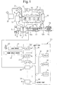
- FIG. 1 is an overall view of a compression ignition type internal combustion engine.
- 1 indicates an engine body, 2 a combustion chamber of each cylinder, 3 an electronically controlled fuel injector for injecting fuel into each combustion chamber 2, 4 an intake manifold, and 5 an exhaust manifold.
- the intake manifold 4 is connected through an intake duct 6 to an outlet of a compressor 7a of an exhaust turbocharger 7, while an inlet of the compressor 7a is connected through an intake air amount detector 8 to an air cleaner 9.
- a throttle valve 10 driven by a step motor is arranged inside the intake duct 6, a throttle valve 10 driven by a step motor is arranged.
- a cooling device 11 is arranged for cooling the intake air which flows through the inside of the intake duct 6.
- the engine cooling water is guided to the inside of the cooling device 11 where the engine cooling water is used to cool the intake air.
- the exhaust manifold 5 is connected to an inlet of an exhaust turbine 7b of the exhaust turbocharger 7.
- An outlet of the exhaust turbine 7b is connected through an exhaust pipe 12a to an inlet of the exhaust purification catalyst 13, while an outlet of the exhaust purification catalyst 13 is connected through an exhaust pipe 12b to a particulate filter 14 for trapping particulate which is contained in exhaust gas.
- a hydrocarbon feed valve 15 is arranged for feeding hydrocarbons comprised of diesel oil or other fuel used as fuel for a compression ignition type internal combustion engine.
- diesel oil is used as the hydrocarbons which are fed from the hydrocarbon feed valve 15.
- the present invention can also be applied to a spark ignition type internal combustion engine in which fuel is burned under a lean air-fuel ratio.
- hydrocarbons comprised of gasoline or other fuel used as fuel of a spark ignition type internal combustion engine are fed.
- the exhaust manifold 5 and the intake manifold 4 are connected with each other through an exhaust gas recirculation (hereinafter referred to as an "EGR") passage 16.
- EGR exhaust gas recirculation
- an electronically controlled EGR control valve 17 is arranged inside the EGR passage 16.
- an electronically controlled EGR control valve 17 is arranged inside the EGR passage 16.
- a cooling device 18 is arranged for cooling EGR gas flowing through the inside of the EGR passage 16.
- the engine cooling water is guided to the inside of the cooling device 18 where the engine cooling water is used to cool the EGR gas.
- each fuel injector 3 is connected through a fuel feed tube 19 to a common rail 20.
- This common rail 20 is connected through an electronically controlled variable discharge fuel pump 21 to a fuel tank 22.
- the fuel which is stored inside of the fuel tank 22 is fed by the fuel pump 21 to the inside of the common rail 20.
- the fuel which is fed to the inside of the common rail 20 is fed through each fuel feed tube 19 to the fuel injector 3.
- An electronic control unit 30 is comprised of a digital computer provided a ROM (read only memory) 32, a RAM (random access memory) 33, a CPU (microprocessor) 34, an input port 35, and an output port 36, which are connected with each other by a bidirectional bus 31.
- ROM read only memory
- RAM random access memory
- CPU microprocessor
- a temperature sensor 24 is arranged for detecting the temperature of the exhaust purification catalyst 13, while at the particulate filter 14, a differential pressure sensor 26 is attached for detecting a differential pressure before and after the particulate filter 14.
- the output signals of these upstream side air-fuel ratio sensor 23, downstream side air-fuel ratio sensor 24, temperature sensor 25, differential pressure sensor 26, and intake air amount detector 8 are input through respectively corresponding AD converters 37 to the input port 35.
- an accelerator pedal 40 has a load sensor 41 connected to it which generates an output voltage proportional to the amount of depression L of the accelerator pedal 40.
- the output voltage of the load sensor 41 is input through a corresponding AD converter 37 to the input port 35.
- a crank angle sensor 42 is connected which generates an output pulse every time a crankshaft rotates by, for example, 15°.
- the output port 36 is connected through corresponding drive circuits 38 to each fuel injector 3, step motor for driving the throttle valve 10, hydrocarbon feed valve 15, EGR control valve 17, and fuel pump 21.
- FIG. 2 schematically shows a surface part of a catalyst carrier which is carried on a substrate of the exhaust purification catalyst 13.
- a catalyst carrier 50 made of alumina on which precious metal catalysts 51 and 52 are carried.
- a basic layer 53 is formed which includes at least one element selected from potassium K, sodium Na, cesium Cs, or another such alkali metal, barium Ba, calcium Ca, or another such alkali earth metal, a lanthanoid or another such rare earth and silver Ag, copper Cu, iron Fe, iridium Ir, or another metal able to donate electrons to NO x .
- the exhaust gas flows along the top of the catalyst carrier 50, so the precious metal catalysts 51 and 52 can be said to be carried on the exhaust gas flow surface of the exhaust purification catalyst 13. Further, the surface of the basic layer 53 exhibits basicity, so the surface of the basic layer 53 is called the basic exhaust gas flow surface part 54.
- the precious metal catalyst 51 is comprised of platinum Pt
- the precious metal catalyst 52 is comprised of rhodium Rh. That is, the precious metal catalysts 51 and 52 which are carried on the catalyst carrier 50 are comprised of platinum Pt and rhodium Rh.
- palladium Pd may be further carried or, instead of rhodium Rh, palladium Pd may be carried. That is, the precious metal catalysts 51 and 52 which are carried on the catalyst carrier 50 are comprised of platinum Pt and at least one of rhodium Rh and palladium Pd.
- FIG. 3 schematically shows the reforming action performed at the exhaust purification catalyst 13 at this time.
- the hydrocarbons HC which are injected from the hydrocarbon feed valve 15 become radical hydrocarbons HC with a small carbon number by the catalyst 51.
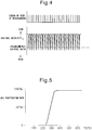
- FIG. 4 shows the feed timing of hydrocarbons from the hydrocarbon feed valve 15 and the change in the air-fuel ratio (A/F)in of the exhaust gas which flows into the exhaust purification catalyst 13.
- the changes in the air-fuel ratio (A/F)in depend on the change in concentration of the hydrocarbons in the exhaust gas which flows into the exhaust purification catalyst 13, so it can be said that the change in the air-fuel ratio (A/F)in shown in FIG. 4 expresses the change in concentration of the hydrocarbons.
- the hydrocarbon concentration becomes higher, the air-fuel ratio (A/F)in becomes smaller, so, in FIG. 4 , the more to the rich side the air-fuel ratio (A/F)in becomes, the higher the hydrocarbon concentration.
- FIG. 5 shows the NO x purification rate by the exhaust purification catalyst 13 with respect to the catalyst temperatures of the exhaust purification catalyst 13 when periodically making the concentration of hydrocarbons which flow into the exhaust purification catalyst 13 change so as to, as shown in FIG. 4 , make the air-fuel ratio (A/F)in of the exhaust gas flowing to the exhaust purification catalyst 13 change.
- the inventors engaged in research relating to NO x purification for a long time. In the process of research, they learned that if making the concentration of hydrocarbons which flow into the exhaust purification catalyst 13 vibrate by within a predetermined range of amplitude and within a predetermined range of period, as shown in FIG. 5 , an extremely high NO x purification rate is obtained even in a 400°C or higher high temperature region.
- FIGS. 6A and 6B schematically show the surface part of the catalyst carrier 50 of the exhaust purification catalyst 13.
- FIGS. 6A and 6B show the reaction which is presumed to occur when the concentration of hydrocarbons which flow into the exhaust purification catalyst 13 is made to vibrate by within a predetermined range of amplitude and within a predetermined range of period.
- FIG. 6A shows when the concentration of hydrocarbons which flow into the exhaust purification catalyst 13 is low
- FIG. 6B shows when hydrocarbons are fed from the hydrocarbon feed valve 15 and the concentration of hydrocarbons which flow into the exhaust purification catalyst 13 becomes higher.
- the air-fuel ratio of the exhaust gas which flows into the exhaust purification catalyst 13 is maintained lean except for an instant, so the exhaust gas which flows into the exhaust purification catalyst 13 normally becomes a state of oxygen excess. Therefore, the NO which is contained in the exhaust gas, as shown in FIG. 6A , is oxidized on the platinum 51 and becomes NO 2 . Next, this NO 2 is further oxidized and becomes NO 3 . Further part of the NO 2 becomes NO 2 - . In this case, the amount of production of NO 3 is far greater than the amount of production of NO 2 - . Therefore, on the platinum Pt 51, a large amount of NO 3 and a small amount of NO 2 - are produced. These NO 3 and NO 2 - are strong in activity. Below, these NO 3 and NO 2 - will be referred to as the active NO x *.
- the hydrocarbons are fed from the hydrocarbon feed valve 15, as shown in FIG. 3 , the hydrocarbons are reformed and become radicalized inside of the exhaust purification catalyst 13. As a result, as shown in FIG. 6B , the hydrogen concentration around the active NO x * becomes higher.
- the active NO x * reacts on the platinum 51 with the radical hydrocarbons HC to thereby form the reducing intermediate. This reducing intermediate is adhered or adsorbed on the surface of the basic layer 53.
- the first produced reducing intermediate is considered to be a nitro compound R-NO 2 . If this nitro compound R-NO 2 is produced, the result becomes a nitrile compound R-CN, but this nitrile compound R-CN can only survive for an instant in this state, so immediately becomes an isocyanate compound R-NCO.
- This isocyanate compound R-NCO becomes an amine compound R-NH 2 if hydrolyzed. However, in this case, what is hydrolyzed is considered to be part of the isocyanate compound R-NCO. Therefore, as shown in FIG. 6B , the majority of the reducing intermediate which is held or adsorbed on the surface of the basic layer 53 is believed to be the isocyanate compound R-NCO and amine compound R-NH 2 .
- the concentration of hydrocarbons which flow into the exhaust purification catalyst 13 is lowered and the oxygen concentration is raised so that the active NO x * reacts with the reducing intermediate and the NO x is removed. That is, in order for the exhaust purification catalyst 13 to remove the NO x , the concentration of hydrocarbons which flow into the exhaust purification catalyst 13 has to be periodically changed.
- the active NO x * is absorbed in the basic layer 53 in the form of nitrates without producing a reducing intermediate. To avoid this, it is necessary to make the concentration of hydrocarbons which flow into the exhaust purification catalyst 13 vibrate by within a predetermined range of period.
- the precious metal catalysts 51 and 52 are carried on the exhaust gas flow surface of the exhaust purification catalyst 13.
- a basic exhaust gas flow surface part 54 is formed around the precious metal catalysts 51 and 52.
- NO x is reduced by the reducing action of the reducing intermediate R-NCO or R-NH 2 held on the basic exhaust gas flow surface part 54, and the vibration period of the hydrocarbon concentration is made the vibration period required for continuation of the production of the reducing intermediate R-NCO or R-NH 2 .
- the injection interval is made 3 seconds.
- the vibration period of the hydrocarbon concentration that is, the feed period of the hydrocarbons HC
- the reducing intermediate R-NCO or R-NH 2 disappears from the surface of the basic layer 53.
- the active NO x * which is produced on the platinum Pt 53, as shown in FIG. 7A , diffuses in the basic layer 53 in the form of nitrate ions NO 3 - and becomes nitrates. That is, at this time, the NO x in the exhaust gas is absorbed in the form of nitrates inside of the basic layer 53.
- FIG. 7B shows the case where the air-fuel ratio of the exhaust gas which flows into the exhaust purification catalyst 13 is made the stoichiometric air-fuel ratio or rich when the NO x is absorbed in the form of nitrates inside of the basic layer 53.
- the oxygen concentration in the exhaust gas falls, so the reaction proceeds in the opposite direction (NO 3 - ⁇ NO 2 ), and consequently the nitrates absorbed in the basic layer 53 become nitrate ions NO 3 - one by one and, as shown in FIG. 7B , are released from the basic layer 53 in the form of NO 2 .
- the released NO 2 is reduced by the hydrocarbons HC and CO contained in the exhaust gas.
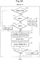
- FIG. 8 shows the case of making the air-fuel ratio (A/F)in of the exhaust gas which flows into the exhaust purification catalyst 13 temporarily rich slightly before the NO x absorption ability of the basic layer 53 becomes saturated.
- the time interval of this rich control is 1 minute or more.
- the NO x which was absorbed in the basic layer 53 when the air-fuel ratio (A/F)in of the exhaust gas was lean is released all at once from the basic layer 53 and reduced when the air-fuel ratio (A/F)in of the exhaust gas is made temporarily rich. Therefore, in this case, the basic layer 53 plays the role of an absorbent for temporarily absorbing NO x .
- the basic layer 53 temporarily adsorbs the NO x . Therefore, if using term of storage as a term including both absorption and adsorption, at this time, the basic layer 53 performs the role of an NO x storage agent for temporarily storing the NO x . That is, in this case, if the ratio of the air and fuel (hydrocarbons) which are supplied into the engine intake passage, combustion chambers 2, and exhaust passage upstream of the exhaust purification catalyst 13 is called the air-fuel ratio of the exhaust gas, the exhaust purification catalyst 13 functions as an NO x storage catalyst which stores the NO x when the air-fuel ratio of the exhaust gas is lean and releases the stored NO x when the oxygen concentration in the exhaust gas falls.
- FIG. 9 shows the NO x purification rate when making the exhaust purification catalyst 13 function as an NO x storage catalyst in this way.
- the abscissa of the FIG. 9 shows the catalyst temperature TC of the exhaust purification catalyst 13.
- the catalyst temperature TC is 300°C to 400°C
- an extremely high NO x purification rate is obtained, but when the catalyst temperature TC becomes a 400°C or higher high temperature, the NO x purification rate falls.
- the NO x purification rate falls because if the catalyst temperature TC becomes 400°C or more, the nitrates break down by heat and are released in the form of NO 2 from the exhaust purification catalyst 13. That is, so long as storing NO x in the form of nitrates, when the catalyst temperature TC is high, it is difficult to obtain a high NO x purification rate.
- the new NO x purification method shown from FIG. 4 to FIGS. 6A and 6B as will be understood from FIGS. 6A and 6B , nitrates are not formed or even if formed are extremely small in amount, consequently, as shown in FIG. 5 , even when the catalyst temperature TC is high, a high NO x purification rate is obtained.
- a hydrocarbon feed valve 15 for feeding hydrocarbons is arranged inside of an engine exhaust passage, downstream of the hydrocarbon feed valve 15 inside of the engine exhaust passage, an exhaust purification catalyst 13 for reacting NO x contained in exhaust gas and reformed hydrocarbons is arranged downstream of the hydrocarbon feed valve 15 in the engine exhaust passage, precious metal catalysts 51 and 52 are carried on the exhaust gas flow surface of the exhaust purification catalyst 13, a basic exhaust gas flow surface part 54 is formed around the precious metal catalysts 51 and 52, the exhaust purification catalyst 13 reducing the NO x which is contained in exhaust gas if the concentration of hydrocarbons which flow into the exhaust purification catalyst 13 is made to vibrate by within a predetermined range of amplitude and within a predetermined range of period and being increased in storage amount of NO x which is contained in exhaust gas if the vibration period of the hydrocarbon concentration is made longer than this predetermined range, and, at the time of engine operation, the concentration of hydrocarbons which flow into the exhaust purification catalyst 13 is made to vibrate by within the predetermined
- the NO x purification method which is shown from FIG. 4 to FIGS. 6A and 6B can be said to be a new NO x purification method designed to remove NO x without forming almost any nitrates in the case of using an exhaust purification catalyst which carries precious metal catalysts and forms a basic layer which can absorb NO x .
- this new NO x purification method when using this new NO x purification method, the nitrates which are detected from the basic layer 53 become much smaller in amount compared with the case where making the exhaust purification catalyst 13 function as an NO x storage catalyst.
- this new NO x purification method will be referred to below as the first NO x purification method.
- FIG. 10 shows enlarged the change in the air-fuel ratio (A/F)in shown in FIG. 4 .
- the change in the air-fuel ratio (A/F)in of the exhaust gas which flows into this exhaust purification catalyst 13 simultaneously shows the change in concentration of the hydrocarbons which flow into the exhaust purification catalyst 13.
- ⁇ H shows the amplitude of the change in concentration of hydrocarbons HC which flow into the exhaust purification catalyst 13
- ⁇ T shows the vibration period of the concentration of the hydrocarbons which flow into the exhaust purification catalyst 13.
- (A/F)b shows the base air-fuel ratio which shows the air-fuel ratio of the combustion gas for generating the engine output.
- this base air-fuel ratio (A/F)b shows the air-fuel ratio of the exhaust gas which flows into the exhaust purification catalyst 13 when stopping the feed of hydrocarbons.
- X shows the upper limit of the air-fuel ratio (A/F)in used for producing the reducing intermediate without the produced active NO x * being stored in the form of nitrates inside the basic layer 53 much at all.
- the air-fuel ratio (A/F)in has to be made lower than this upper limit X of the air-fuel ratio.
- X shows the lower limit of the concentration of hydrocarbons required for making the active NO x * and reformed hydrocarbons react to produce a reducing intermediate.
- the concentration of hydrocarbons has to be made higher than this lower limit X.
- whether the reducing intermediate is produced is determined by the ratio of the oxygen concentration and hydrocarbon concentration around the active NO x *, that is, the air-fuel ratio (A/F)in.
- the upper limit X of the air-fuel ratio required for producing the reducing intermediate will below be called the demanded minimum air-fuel ratio.
- the demanded minimum air-fuel ratio X is rich, therefore, in this case, to form the reducing intermediate, the air-fuel ratio (A/F)in is instantaneously made the demanded minimum air-fuel ratio X or less, that is, rich.
- the demanded minimum air-fuel ratio X is lean. In this case, the air-fuel ratio (A/F)in is maintained lean while periodically reducing the air-fuel ratio (A/F)in so as to form the reducing intermediate.
- the exhaust purification catalyst 13 determines whether the demanded minimum air-fuel ratio X becomes rich or becomes lean depending on the oxidizing strength of the exhaust purification catalyst 13.
- the exhaust purification catalyst 13 for example, becomes stronger in oxidizing strength if increasing the carried amount of the precious metal 51 and becomes stronger in oxidizing strength if strengthening the acidity. Therefore, the oxidizing strength of the exhaust purification catalyst 13 changes due to the carried amount of the precious metal 51 or the strength of the acidity.
- the demanded minimum air-fuel ratio X has to be reduced the stronger the oxidizing strength of the exhaust purification catalyst 13. In this way the demanded minimum air-fuel ratio X becomes lean or rich due to the oxidizing strength of the exhaust purification catalyst 13.
- the amplitude of the change in concentration of hydrocarbons which flow into the exhaust purification catalyst 13 and the vibration period of the concentration of hydrocarbons which flow into the exhaust purification catalyst 13 will be explained.
- the base air-fuel ratio (A/F)b becomes larger, that is, if the oxygen concentration in the exhaust gas before the hydrocarbons are fed becomes higher, the feed amount of hydrocarbons required for making the air-fuel ratio (A/F)in the demanded minimum air-fuel ratio X or less increases and along with this the excess amount of hydrocarbons which do not contribute to the production of the reducing intermediate also increases.
- the feed amount of hydrocarbons required for making the air-fuel ratio (A/F)in the demanded minimum air-fuel ratio X or less increases and along with this the excess amount of hydrocarbons which do not contribute to the production of the reducing intermediate also increases.
- the NO x well as explained above, it is necessary to make the excess hydrocarbons oxidize. Therefore, to remove the NO x well, the larger the amount of excess hydrocarbons, the larger the amount of oxygen which is required.
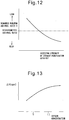
- FIG. 13 shows the relationship between the oxygen concentration in the exhaust gas before the hydrocarbons are fed and the amplitude ⁇ H of the hydrocarbon concentration when the same NO x purification rate is obtained.
- the base air-fuel ratio (A/F)b becomes the lowest at the time of an acceleration operation. At this time, if the amplitude ⁇ H of the hydrocarbon concentration is about 200 ppm, it is possible to remove the NO x well.
- the base air-fuel ratio (A/F)b is normally larger than the time of acceleration operation. Therefore, as shown in FIG. 14 , if the amplitude ⁇ H of the hydrocarbon concentration is 200 ppm or more, an excellent NO x purification rate can be obtained.
- the base air-fuel ratio (A/F)b is the highest, if making the amplitude ⁇ H of the hydrocarbon concentration 10000 ppm or so, an excellent NO x purification rate is obtained. Therefore, the predetermined range of the amplitude of the hydrocarbon concentration is made 200 ppm to 10000 ppm.
- the vibration period ⁇ T of the hydrocarbon concentration becomes longer, the oxygen concentration around the active NO x * becomes higher in the time period after the hydrocarbons are fed to when the hydrocarbons are next fed.
- the vibration period ⁇ T of the hydrocarbon concentration becomes longer than about 5 seconds, the majority of the active NO x * starts to be absorbed in the form of nitrates inside the basic layer 53. Therefore, as shown in FIG. 15 , if the vibration period ⁇ T of the hydrocarbon concentration becomes longer than about 5 seconds, the NO x purification rate falls. Therefore, the vibration period ⁇ T of the hydrocarbon concentration has to be made 5 seconds or less.
- the vibration period of the hydrocarbon concentration is made from 0.3 second to 5 seconds.
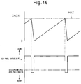
- an NO x purification method in the case when making the exhaust purification catalyst 13 function as an NO x storage catalyst will be explained in detail.
- the NO x purification method in the case when making the exhaust purification catalyst 13 function as an NO x storage catalyst in this way will be referred to below as the second NO x purification method.
- this second NO x purification method as shown in FIG. 16 , when the stored NO x amount ⁇ NOX of NO x which is stored in the basic layer 53 exceeds a predetermined allowable amount MAX, the air-fuel ratio (A/F)in of the exhaust gas flowing into the exhaust purification catalyst 13 is temporarily made rich. If the air-fuel ratio (A/F)in of the exhaust gas is made rich, the NO x which was stored in the basic layer 53 when the air-fuel ratio (A/F)in of the exhaust gas was lean is released from the basic layer 53 all at once and reduced. Due to this, the NO x is removed.
- the stored NO x amount ⁇ NOX is, for example, calculated from the amount of NO x which is exhausted from the engine.
- the exhausted NO x amount NOXA of NO x which is exhausted from the engine per unit time is stored as a function of the engine output torque Te and engine speed N in the form of a map such as shown in FIG. 17 in advance in the ROM 32.
- the stored NO x amount ⁇ NOX is calculated from the exhausted NO x amount NOXA. In this case, as explained before, the period during which the air-fuel ratio (A/F)in of the exhaust gas is made rich is usually 1 minute or more.
- the fuel injector 3 injects additional fuel WR into the combustion chamber 2 in addition to the output generation-use fuel Q so that the air-fuel ratio (A/F)in of the exhaust gas which flows into the exhaust purification catalyst 13 is made rich.
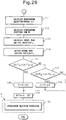
- the abscissa indicates the crank angle.
- This additional fuel WR is injected at a timing at which it will burn, but will not appear as engine output, that is, slightly before ATDC90° after compression top dead center.
- This fuel amount WR is stored as a function of the engine output torque Te and engine speed N in the form of a map such as shown in FIG. 19 in advance in the ROM 32.
- the amplitude ⁇ H and vibration period ⁇ T of the hydrocarbon concentration have to be suitably controlled. That is, to use the first NO x purification method to remove the NO x well, it is necessary to control the amplitude ⁇ H of the hydrocarbon concentration so that the air-fuel ratio (A/F)in of the exhaust gas which flows into the exhaust purification catalyst 13 becomes the demanded minimum air-fuel ratio X or less, and it is necessary to control the vibration period ⁇ T of the hydrocarbon concentration to 0.3 second to 5 seconds.
- the amplitude ⁇ H of the hydrocarbon concentration is controlled by controlling the injection amount of hydrocarbons from the hydrocarbon feed valve 15 and the vibration period ⁇ T of the hydrocarbon concentration is controlled by controlling the injection period of hydrocarbons from the hydrocarbon feed valve 15.
- the injection amount of hydrocarbons from the hydrocarbon feed valve 15 can be controlled by controlling at least one of the injection time or injection pressure of hydrocarbons from the hydrocarbon feed valve 15.
- the present invention will be explained with reference to the case of controlling the injection amount by controlling the injection time while holding the injection pressure constant.
- FIG. 20A shows the optimal base air-fuel ratio (A/F)b which is found by experiments as a function of the engine speed N and engine output torque Te. Note that, the solid lines in FIG. 20A express the equivalent air-fuel ratio lines of the air-fuel ratios shown by the numerical values.
- the fuel injection amount from the fuel injector 3 is controlled so that the air-fuel ratio of the exhaust gas which is exhausted from the engine becomes the optimal base air-fuel ratio (A/F)b which is shown in FIG. 20A .
- the optimal base air-fuel ratio (A/F)b which is shown in FIG. 20A is stored as a function of the engine speed N and engine output torque Te in the form of a map such as shown in FIG. 20B in advance in the ROM 32.
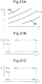
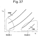
- FIG. 21A shows the optimal hydrocarbon injection period ⁇ T which is found by experiments as a function of the engine speed N and the engine output torque Te. Note that, the solid lines in FIG. 21A show the equivalent hydrocarbon injection periods. As will be understood from FIG. 21A , the optimal hydrocarbon injection period ⁇ T becomes shorter the lower the engine speed N and becomes shorter the higher the engine output torque Te.
- the optimal hydrocarbon injection period ⁇ T which is shown in FIG. 21A is stored as a function of the engine speed N and the engine output torque Te in the form of a map such as shown in FIG. 21B in advance in the ROM 32. Further, the optimal hydrocarbon injection period WT which is found by experiments is also stored as a function of the engine speed N and engine output torque Te in the form of a map such as shown in FIG. 20C in advance in the ROM 32.
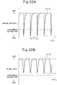
- FIG. 22A shows a change of the air-fuel ratio (A/F)in of the exhaust gas which flows into the exhaust purification catalyst 13 when the hydrocarbon injection period is made the optimal hydrocarbon injection period ⁇ T which is shown in FIG. 21B and the hydrocarbon injection period is made the optimal hydrocarbon injection period WT which is shown in FIG. 21C
- FIG. 22B shows a change in the air-fuel ratio which is detected by the downstream side air-fuel ratio sensor 24 at this time.
- a rich side peak air-fuel ratio (A/F)r of the air-fuel ratio (A/F)in of the exhaust gas which flows into the exhaust purification catalyst 13 becomes rich, while a rich side peak air-fuel ratio (A/F)p of the air-fuel ratio which is detected by the downstream side air-fuel ratio sensor 24 becomes lean.
- A/F rich side peak air-fuel ratio
- A/F rich side peak air-fuel ratio
- the rich side peak air-fuel ratio (A/F)p which is detected by the downstream side air-fuel ratio sensor 24 when the hydrocarbon injection period is made the optimal hydrocarbon injection period ⁇ T which is shown in FIG. 21B and the hydrocarbon injection period is made the optimal hydrocarbon injection period WT which is shown in FIG. 21C is found in advance by experiments.
- the rich side peak air-fuel ratio (A/F)p which is found in advance by experiments is stored in advance as the target peak air-fuel ratio (A/F)t with respect to the different engine operating states.
- This target peak air-fuel ratio (A/F)t is stored as a function of the engine speed N and engine output torque Te in the form of a map as shown in FIG. 23 in advance in the ROM 32.
- FIG. 24 schematically shows the relationship between the output current I of the air-fuel ratio sensors 23 and 24 and the air-fuel ratio. From FIG. 24 , it will be understood that the output current I of the air-fuel ratio sensors 23 and 24 changes in accordance with the air-fuel ratio and therefore it is possible to detect the air-fuel ratio from the output current I of the air-fuel ratio sensors 23 and 24.
- the hydrocarbon injection period deviates from the optimal hydrocarbon injection period WT which is shown in FIG. 21C , the rich side peak air-fuel ratio (A/F)p of the air-fuel ratio which is detected by the downstream side air-fuel ratio sensor 24 also deviates from the target peak air-fuel ratio (A/F)t which is shown in FIG. 23 .
- the hydrocarbon injection period becomes the optimal hydrocarbon injection period WT which is shown in FIG. 21C and as a result the maximum NOx purification rate can be secured.
- the downstream side air-fuel ratio sensor 24 for detecting the air-fuel ratio of the exhaust gas is arranged in the engine exhaust passage downstream of the exhaust purification catalyst 13, and the injection amount of hydrocarbons from the hydrocarbon feed valve 15 is controlled based on the output signal of the downstream side air-fuel ratio sensor 24 so that the amplitude of the change in concentration of hydrocarbons which flows into the exhaust purification catalyst 13 becomes within a predetermined range of amplitude.
- the injection amount of hydrocarbons from the hydrocarbon feed valve 15 is made to increase, while when the rich side peak air-fuel ratio (A/F)p which is detected by the downstream side air-fuel ratio sensor 24 becomes the rich side from the predetermined air-fuel ratio (A/F)t, the injection amount of hydrocarbons from the hydrocarbon feed valve 15 is made to decrease,
- this routine is executed by interruption every a fixed time period.
- step 60 it is judged from the output signal of the temperature sensor 25 if a temperature TC of the exhaust purification catalyst 13 exceeds an activation temperature TCo.
- TC ⁇ TCo that is, when the exhaust purification catalyst 13 is not activated, it is judged that the second NO x purification method should be used, then the routine proceeds to step 61.
- the NO x amount NOXA exhausted per unit time is calculated from the map which is shown in FIG. 17 .
- step 62 the exhausted NO x amount NOXA is added to the ⁇ NOX so as to calculate the stored NO x amount ⁇ NOX.
- step 63 it is judged if the stored NO x amount ⁇ NOX exceeds the allowable value MAX.
- step 64 processing is performed for injecting fuel from the fuel injector 3. At this time, fuel is injected from the fuel injector 3 so as to give a predetermined lean air-fuel ratio which is determined from the operating state of the engine.
- step 65 the rich control I is performed. That is, the additional fuel amount WR is calculated from the map which is shown in FIG. 19 and the injection action of additional fuel is performed. At this time, the stored NO x is released from the exhaust purification catalyst 13.
- step 66 ⁇ NOX is cleared.
- step 60 when it is judged at step 60 that TC ⁇ TCo, that is, when the exhaust purification catalyst 13 is activated, the routine proceeds to step 67 where it is judged if TC ⁇ TCo at the time of the previous interruption.
- step 68 the rich control II is performed.
- the additional fuel amount WR is calculated from the map which is shown in FIG. 19 , the action of injection of the additional fuel is performed, and the stored NO x is released from the exhaust purification catalyst 13.
- step 69 ⁇ NOX is cleared.
- step 70 the routine proceeds to step 70 where the operational control I is performed.
- an NO x purification action is performed by the first NO x purification method according to the present invention. That is, when the exhaust purification catalyst 13 is not activated, an NO x purification action is performed by the second NO x purification method. If the exhaust purification catalyst 13 is activated, the second NO x purification method is switched to the first NO x purification method.
- the second NO x purification method is switched to the first NO x purification method, if the exhaust purification catalyst 13 stores NO x , the NO x which is stored from the exhaust purification catalyst 13 is released all at once without being reduced. Therefore, in the example which is shown in FIG. 25 , to stop the NO x which is stored from the exhaust purification catalyst 13 in this way being released all at once without being reduced, right before the second NO x purification method is switched to the first NO x purification method, at step 68, the rich control II is performed for releasing the stored NO x from the exhaust purification catalyst 13 by the second NO x purification method.
- FIG. 26 and FIG. 27 show a first embodiment of this operational control I.
- the target value of the base air-fuel ratio that is, the target air-fuel ratio (A/F)b
- the intake air amount GA is calculated from the output signal of the intake air amount detector 8.
- the fuel injection amount Q for generation of output from the fuel injector 3 which is required for making the base air-fuel ratio the target air-fuel ratio (A/F)b is calculated from the target air-fuel ratio (A/F)b and the intake air amount GA.
- the fuel injection time QT is calculated from this fuel injection amount Q
- fuel injection processing is performed to inject fuel from the fuel injector 3 in accordance with this fuel injection time QT.
- the optimal hydrocarbon injection period ⁇ T is calculated from the map which is shown in FIG. 21B .
- the optimal hydrocarbon injection period WT is calculated from the map which is shown in FIG. 21C .
- the target peak air-fuel ratio (A/F)t is calculated from the map which is shown in FIG. 23 .
- the actual rich side peak air-fuel ratio (A/F)p is detected from the output of the downstream side air-fuel ratio sensor 24.
- step 89 it is judged if the actual rich side peak air-fuel ratio (A/F)p is larger than the value of the target peak air-fuel ratio (A/F)t plus a small constant value ⁇ .
- the routine proceeds to step 90 where a constant value ⁇ K is added to the correction coefficient K for the hydrocarbon injection period WT.
- the routine proceeds to step 93 where a hydrocarbon injection period WT multiplied with the correction coefficient K (K ⁇ WT) is made the final hydrocarbon injection period WTO.
- step 89 when it is judged at step 89 that (A/F)p>(A/F)t+ ⁇ does not stand, the routine proceeds to step 91 where it is judged if the actual rich side peak air-fuel ratio (A/F)p is smaller than the target peak air-fuel ratio (A/F)t minus the constant value ⁇ .
- step 92 the correction coefficient K is reduced by the constant value ⁇ K whereupon the routine proceeds to step 93.
- step 94 hydrogen injection processing is performed to inject hydrocarbons from the hydrocarbon feed valve 15 in accordance with the final hydrocarbon injection period WTO.
- the fuel injection amount Q for generation of output which is required for making the base air-fuel ratio the target air-fuel ratio (A/F)b is calculated based on the intake air amount GA which is detected by the intake air detector 8, then the fuel injection time QT is calculated from this fuel injection amount Q.
- the base air-fuel ratio is held at the target air-fuel ratio (A/F)b.
- the base air-fuel ratio will no longer match the target air-fuel ratio (A/F)b.
- the downstream side air-fuel ratio sensor 24 is used to make the actual rich side peak air-fuel ratio (A/F)p the target peak air-fuel ratio (A/F)t by feedback control of the hydrocarbon feed amount.
- the actual rich side peak air-fuel ratio (A/F)p is controlled to become the target peak air-fuel ratio (A/F)t. That is, in the first embodiment of this operational control I, even if the base air-fuel ratio deviates, the actual rich side peak air-fuel ratio (A/F)p is controlled to become the target peak air-fuel ratio (A/F)t.
- the rich side peak air-fuel ratio (A/F)r of the air-fuel ratio (A/F)in of the exhaust gas flowing into the exhaust purification catalyst 13, which gives the highest NOx purification rate is determined with respect to the base air-fuel ratio.
- This rich side peak air-fuel ratio (A/F)r which gives the highest NO x purification rate changes commensurately if the base air-fuel ratio changes. Therefore, when the base air-fuel ratio deviates from the target air-fuel ratio (A/F)b, the base air-fuel ratio is preferably returned to the target air-fuel ratio (A/F)b.
- the upstream side air-fuel ratio sensor 23 is used to control the base air-fuel ratio to the target air-fuel ratio (A/F)b. That is, in the second embodiment of this operational control I, the air-fuel ratio of the exhaust gas which is exhausted from the engine is detected by the upstream side air-fuel ratio sensor 23, and the fuel injection time QT from the fuel injector 3 is corrected so that the detected air-fuel ratio becomes the target air-fuel ratio (A/F)b. If using the upstream side air-fuel ratio sensor 23 in this way, even if the intake air amount detector 8 deteriorates, the base air-fuel ratio can be maintained at the target air-fuel ratio (A/F)b.
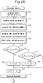
- steps 100 to 103 are the same as steps 80 to 83 of FIG. 26 .
- steps 111 and 120 are the same as steps 85 to 94 of FIG. 26 and FIG. 27 .
- the target value of the base air-fuel ratio that is, the target air-fuel ratio (A/F)b
- the intake air amount GA is calculated from the output signal of the intake air amount detector 8.
- the fuel injection amount Q for output generation from the fuel injector 3 which is required for making the base air-fuel ratio the target air-fuel ratio (A/F)b is calculated.
- the fuel injection time QT is calculated from this fuel injection amount Q.
- step 104 the output of the upstream side air-fuel ratio sensor 23 is used as the basis to detect the actual air-fuel ratio (A/F)a of the exhaust gas which is exhausted from the engine.
- step 105 it is judged if the actual air-fuel ratio (A/F)a is larger than the target air-fuel ratio (A/F)b plus a small constant value ⁇ .
- the routine proceeds to step 106 where the correction coefficient G for the fuel injection time QT is increased by a constant value ⁇ G.
- the routine proceeds to step 106 where the fuel injection time QT multiplied with the correction coefficient G, that is, the value (G ⁇ QT), is made the final fuel injection time QTO.
- step 105 when it is judged at step 105 that (A/F)a>(A/F)b+ ⁇ does not stand, the routine proceeds to step 107 where it is judged if the actual air-fuel ratio (A/F)a of the exhaust gas which is exhausted from the engine is smaller than the target peak air-fuel ratio (A/F)b minus a constant value ⁇ .
- step 108 the routine proceeds to step 108 where the correction coefficient G is reduced by a constant value ⁇ G, then the routine proceeds to step 109.
- step 110 processing is performed to inject fuel from the fuel injector 3 in accordance with the fuel injection time QTO.
- the optimal hydrocarbon injection period ⁇ T is calculated from the map which is shown in FIG. 21B .
- the optimal hydrocarbon injection period WT is calculated from the map which is shown in FIG. 21C .
- the target peak air-fuel ratio (A/F)t is calculated from the map which is shown in FIG. 23 .
- the actual rich side peak air-fuel ratio (A/F)p is detected from the output of the downstream side air-fuel ratio sensor 24.
- step 115 it is judged if the actual rich side peak air-fuel ratio (A/F)p is larger than the target peak air-fuel ratio (A/F)t plus a small constant value ⁇ .
- the routine proceeds to step 116 where the correction coefficient K for the hydrocarbon injection period WT is increased by a constant value ⁇ K.
- the routine proceeds to step 119 where the hydrocarbon injection period WT multiplied with the correction coefficient K, that is, the value (K ⁇ WT), is made the final hydrocarbon injection period WTO.
- step 115 when it is judged at step 115 that(A/F)p>(A/F)t+ ⁇ does not stand, the routine proceeds to step 117 where it is judged if the actual rich side peak air-fuel ratio (A/F)p is smaller than the target peak air-fuel ratio (A/F)t minus a constant value ⁇ .
- step 118 the correction coefficient K is reduced by a constant value ⁇ K, then the routine proceeds to step 119.
- step 120 hydrocarbon injection processing is performed for injecting hydrocarbons from the hydrocarbon feed valve 15 in accordance with the final hydrocarbon injection period WTO.
- the injection amount of hydrocarbons from the hydrocarbon feed valve 15 is controlled so that the amplitude of the change in concentration of hydrocarbons which flow into the exhaust purification catalyst 13 becomes within a predetermined range of amplitude.
- the amount of fuel which is fed to the engine combustion chamber 2 is controlled based on the output signal of the upstream side air-fuel ratio sensor 23 so that the air-fuel ratio of the exhaust gas which is exhausted from the engine, that is, the base air-fuel ratio, becomes a predetermined air-fuel ratio, that is, the target air-fuel ratio (A/F)b.
- the rich side peak air-fuel ratio (A/F)p of the exhaust gas which flows out from the exhaust purification catalyst 13 is controlled to become the target peak air-fuel ratio (A/F)t.
- the rich side peak air-fuel ratio (A/F)r of the air-fuel ratio (A/F)in of the exhaust gas which flows into the exhaust purification catalyst 13 is accurately controlled to the target air-fuel ratio (A/F)b, so a high NO x purification rate can be obtained.
- the actual air-fuel ratio (A/F)a which is detected by the upstream side air-fuel ratio sensor 23 and the actual rich side peak air-fuel ratio (A/F)p which is detected by the downstream side air-fuel ratio sensor 24 are used to calculate the hydrocarbon injection period WTO from the hydrocarbon feed valve 15 from the difference between the actual air-fuel ratio (A/F)a which is detected by the upstream side air-fuel ratio sensor 23 and the target air-fuel ratio (A/F)b and the difference of the actual rich side peak air-fuel ratio (A/F)p which is detected from the downstream side air-fuel ratio sensor 24 and the target peak air-fuel ratio (A/F)t on the basis of the following formula.
- WT is the hydrocarbon injection period from the hydrocarbon feed valve 15 which is calculated from the map of FIG. 21C
- K1 and K2 are positive constants.
- the injection amount of hydrocarbons from the hydrocarbon feed valve 15 is increased, while when the rich side peak air-fuel ratio which is detected by the downstream side air-fuel ratio sensor 24 is at the rich side from the predetermined air-fuel ratio, the injection amount of hydrocarbons from the hydrocarbon feed valve 15 is made to decrease.
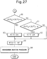
- FIG. 30 shows the routine of the third embodiment of the operational control I which is performed at step 70 of FIG. 25 .
- the target value of the base air-fuel ratio that is, the target air-fuel ratio (A/F)b
- the upstream side air-fuel ratio sensor 23 is used to detect the actual air-fuel ratio (A/F)a of the exhaust gas which is exhausted from the engine.
- the intake air amount GA is calculated from the output signal of the intake air amount detector 8.
- the fuel injection amount Q for generation of output from the fuel injector 3 which is required for making the base air-fuel ratio the target air-fuel ratio (A/F)b is calculated from the target air-fuel ratio (A/F)b and the intake air amount GA.
- the fuel injection time QT is calculated from this fuel injection amount Q, next, at step 135, fuel injection processing is performed to inject fuel from the fuel injector 3 in accordance with this fuel injection time QT.
- the optimal hydrocarbon injection period ⁇ T is calculated from the map which is shown in FIG. 21B .
- the optimal hydrocarbon injection period WT is calculated from the map which is shown in FIG. 21C .
- the target peak air-fuel ratio (A/F)t is calculated from the map which is shown in FIG. 23 .
- the actual rich side peak air-fuel ratio (A/F)p is detected from the output of the downstream side air-fuel ratio sensor 24.
- the hydrocarbon injection period WTO from the hydrocarbon feed valve 15 is calculated based on the following formula. WTO ⁇ WT ⁇ 1 + K 1 ⁇ A / F a ⁇ A / F b + K 2 ⁇ A / F p ⁇ A / F t
- step 141 hydrocarbon injection processing is performed to inject hydrocarbons from the hydrocarbon feed valve 15 in accordance with the calculated hydrocarbon injection period WTO.
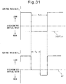
- FIG. 31 shows the changes in the air-fuel ratio of the exhaust gas (A/F)a which flows into the exhaust purification system 13 and the changes in the air-fuel ratio of the exhaust gas (A/F)c which is exhausted from the exhaust purification system 13 when this rich control II is performed.
- the time period trt where the air-fuel ratio of the inflowing exhaust gas (A/F)a is made rich is several seconds. This time period trt is made to change in accordance with the amount of the stored NO x .
- (A/F)rt shows the target rich air-fuel ratio when rich control II is performed.
- the additional fuel amount WR fed into the combustion chamber 2 is controlled by learning each time rich control II is performed so that the actual air-fuel ratio (A/F)a which is detected by the upstream side air-fuel ratio sensor 23 becomes the target rich air-fuel ratio (A/F)rt.
- the exhaust purification system 13 has the ability to store oxygen in the catalyst.
- the exhaust purification system 13 has an oxygen storing ability
- the air-fuel ratio of the inflowing exhaust gas (A/F)a is made rich
- the excessive hydrocarbons in the exhaust gas react with the stored oxygen and are oxidized.
- the air-fuel ratio of the discharged exhaust gas (A/F)c is maintained at the stoichiometric air-fuel ratio as shown by the time period ts of FIG. 31 .
- the exhaust purification system 13 deteriorates, the oxygen storing ability falls.
- the time period ts during which the air-fuel ratio of the exhaust gas (A/F)c which is exhausted is maintained at the stoichiometric air-fuel ratio becomes shorter. Therefore, it is possible to detect that the exhaust purification system 13 has deteriorated by the time period ts during which the air-fuel ratio of the exhaust gas (A/F)c which is discharged is maintained at the stoichiometric air-fuel ratio becoming shorter.
- FIG. 32 and FIG. 33 which show this rich control II will be explained.
- step 150 the fuel injection amount Q for generation of output which is shown in FIG. 18 is calculated and the additional fuel amount WR is calculated from the map which is shown in FIG. 19 .
- step 151 the actual air-fuel ratio of the inflowing exhaust gas (A/F)a is detected by the upstream side air-fuel ratio sensor 23.
- step 152 it is judged if the air-fuel ratio of the inflowing exhaust gas (A/F)a is larger than the target rich air-fuel ratio (A/F)rt plus a small constant value d.
- step 153 the routine proceeds to step 153 where the constant value ⁇ GR is added to the learned value GR for the additional fuel amount WR.
- step 156 the routine proceeds to step 156 where the additional fuel amount WR multiplied with the learned value GR (GR ⁇ WR) is made the final additional fuel amount WRO.
- step 152 when it is judged at step 152 that (A/F)a>(A/F)rt+d does not stand, the routine proceeds to step 154 where it is judged if the actual air-fuel ratio of the inflowing exhaust gas (A/F)a is smaller than the target peak air-fuel ratio (A/F)rt minus a constant value ⁇ .
- step 155 When (A/F)a ⁇ (A/F)rt-d, the routine proceeds to step 155 where a constant value ⁇ GR is subtracted from the learned value GR, then the routine proceeds to step 156.
- step 157 fuel injection processing is performed to inject the additional fuel WRO in addition to the fuel injection amount Q from the fuel injector 3 in accordance with the final additional fuel amount WRO.
- step 158 the actual air-fuel ratio of the discharged exhaust gas (A/F)c is detected by the downstream side air-fuel ratio sensor 24.
- step 159 it is judged if the actual air-fuel ratio of the discharged exhaust gas (A/F)c is smaller than the stoichiometric air-fuel ratio plus a small constant value h and is larger than the stoichiometric air-fuel ratio minus the constant value h, that is, the air-fuel ratio of the exhausted exhaust gas (A/F)c, is about the stoichiometric air-fuel ratio.
- step 160 When the air-fuel ratio of the exhausted exhaust gas (A/F)c is about the stoichiometric air-fuel ratio, the routine proceeds to step 160 where a fixed time ⁇ t is added to the stoichiometric air-fuel ratio duration Ts.
- step 161 the ⁇ t time is waited, then the routine proceeds to step 162 where it is judged if the rich time which is shown by trt in FIG. 31 has elapsed.
- the routine returns to step 150. That is, until the rich time elapses, the routine returns to step 150 every ⁇ t time.
- the routine proceeds to step 163 where it is judged if the stoichiometric air-fuel ratio duration Ts is longer than the deterioration judgment reference time XTs.
- the base air-fuel ratio is controlled based on the output signal of the upstream side air-fuel ratio sensor 23 so as to be maintained at the target air-fuel ratio (A/F)b.
- the output signal of the downstream side air-fuel ratio sensor 24 is used as the basis so that the rich side peak air-fuel ratio (A/F)r of the air-fuel ratio (A/F)in of the exhaust gas which flows into the exhaust purification catalyst 13 is accurately controlled to the target air-fuel ratio (A/F)b, so a high NO x purification rate can be obtained.
- the base air-fuel ratio is maintained at the target air-fuel ratio (A/F)b and the rich side peak air-fuel ratio (A/F)r of the air-fuel ratio (A/F)in of the exhaust gas which flows into the exhaust purification catalyst 13 is accurately controlled to the target air-fuel ratio (A/F)b in this way, if an abnormality occurs in the exhaust purification system, for example, if an abnormality occurs in the hydrocarbon feed action of the hydrocarbon feed valve 15, the effect of that abnormality appears quickly in the output signal of the downstream side air-fuel ratio sensor 24.
- the output signal of the downstream side air-fuel ratio sensor 24 is used as the basis for performing the diagnosis of the trouble of the exhaust purification system.
- the hydrocarbon feed valve 15 becomes clogged, the feed amount of hydrocarbons from the hydrocarbon feed valve 15 is decreased. Therefore, when the base air-fuel ratio is maintained at the target air-fuel ratio (A/F)b and the rich side peak air-fuel ratio (A/F)r of the air-fuel ratio (A/F)in of the exhaust gas which flows into the exhaust purification catalyst 13 is accurately controlled to the target air-fuel ratio (A/F)b, that is, when the second embodiment of operational control I which is shown in FIG. 28 and FIG. 29 is being performed, if the hydrocarbon feed valve 15 is clogged and the feed amount of hydrocarbons from the hydrocarbon feed valve 15 is decreased, the correction coefficient K which is shown in steps 116, 118, and 119 of FIG. 29 is made to increase to make the rich side peak air-fuel ratio (A/F)r of the air-fuel ratio (A/F)in of the exhaust gas which flows into the exhaust purification catalyst 13 match the target air-fuel ratio (A/F)b.
- the value of the correction coefficient K when the amount of clogging of the hydrocarbon feed valve 15 becomes over an allowable amount is stored as a limit value XK in advance. When the value of the correction coefficient K exceeds this limit value XK, an alarm is issued showing that the hydrocarbon feed valve 15 has become clogged.
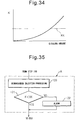
- FIG. 36A shows the change in the air-fuel ratio which is detected by the downstream side air-fuel ratio sensor 24 when the NO x purification action by the first NO x purification method is being performed.
- the air-fuel ratio which is detected by the downstream side air-fuel ratio sensor 24 usually, as shown in I of FIG. 36 , vibrates to the rich side from the base air-fuel ratio (A/F)b. That is, when the injection period of hydrocarbons from the hydrocarbon feed valve 15 is controlled so that the concentration of hydrocarbons which flow into the exhaust purification catalyst 13 vibrates by within a predetermined range of period, the air-fuel ratio which is detected by the downstream side air-fuel ratio sensor 24 usually vibrates to the rich side from the base air-fuel ratio (A/F)b.
- the area S of the part which is shown by hatching that is, the integrated value of the difference between the air-fuel ratio which is detected by the downstream side air-fuel ratio sensor 24 and the base air-fuel ratio (A/F)b, expresses the actual injection amount of hydrocarbons per injection from the hydrocarbon feed valve 15. Note that, the above-mentioned area S and integrated value show the area S and integrated value per fluctuation of the air-fuel ratio. This same is true below as well.
- This area S can be calculated from the target injection amount of hydrocarbons which is calculated in accordance with the operating state of the engine.
- the surface area S which is calculated from the target injection amount in this way is called the reference area So.
- the area S becomes equal to the reference area So.
- the area S will not become equal to the reference area So. For example, when the actually injected injection amount is smaller compared with the target injection amount, the area S becomes smaller than the reference area So.
- the hydrocarbon feed valve 15 it is judged if hydrocarbons are being normally injected from the hydrocarbon feed valve 15, for example, if the hydrocarbon feed valve 15 is clogged on the basis of the integrated value of the difference between the air-fuel ratio detected by the downstream side air-fuel ratio sensor 24 and the base air-fuel ratio (A/F)b.
- the hydrocarbon feed valve 15 is clogged on the basis of the integrated value of the difference between the air-fuel ratio detected by the downstream side air-fuel ratio sensor 24 and the base air-fuel ratio (A/F)b.
- the area S becomes smaller than the reference area So multiplied with a constant value C ( ⁇ 1.0), that is, the value C ⁇ So, it is judged that the hydrocarbon feed valve 15 is clogged.
- the air-fuel ratio which is detected by the downstream side air-fuel ratio sensor 24 changes toward the rich side before returning to the base air-fuel ratio (A/F)b due to the next injection action of hydrocarbons. If the air-fuel ratio which is detected by the downstream side air-fuel ratio sensor 24 no longer returns to the base air-fuel ratio (A/F)b in this way, the calculated surface area S no longer will express the actual hydrocarbon injection amount.
- the injection period of hydrocarbons is too short for accurately detecting the injection amount of hydrocarbons from the hydrocarbon feed valve 15, the injection period of hydrocarbons is made longer. Further, in this case, the amount of hydrocarbons which is supplied is prevented from becoming insufficient by increasing the injection amount of hydrocarbons per injection from the hydrocarbon feed valve 15.
- the injection amount of hydrocarbons from the hydrocarbon feed valve 15 can no longer be accurately detected. Therefore, in the embodiment according to the present invention, as shown by I in FIG. 36C , to prevent hydrocarbons from passing straight through the exhaust purification catalyst 13 when the injection amount of hydrocarbons per injection from the hydrocarbon feed valve 15 is large, as shown by II in FIG. 36C , the injection amount of hydrocarbons per injection from the hydrocarbon feed valve 15 is reduced.
- the injection amount of hydrocarbons when using the integrated value of the difference between the air-fuel ratio detected by the downstream side air-fuel ratio sensor 24 and the base air-fuel ratio (A/F)b as the basis to judge if the hydrocarbon feed valve 15 is clogged, if the injection amount of hydrocarbons becomes too great for accurately detecting the injection amount of hydrocarbons from the hydrocarbon feed valve 15, the injection amount of hydrocarbons is made smaller.
- step 170 it is judged if the timing is one for trouble diagnosis.
- step 173 processing is performed for injecting hydrocarbons from the hydrocarbon feed valve 15.
- step 171 it is judged if the operating state of the engine is in the operating region A which is shown in FIG. 37 .
- step 172 it is judged if the operating state of the engine is in the operating region B which is shown in FIG. 37 .
- the routine proceeds to step 173.
- step 171 when it is judged at step 171 that the operating state of the engine is in the operating region A which is shown in FIG. 37 , the routine proceeds to step 174 where the injection period of hydrocarbons ⁇ T from the hydrocarbon feed valve 15 is multiplied with a predetermined correction value F (>1.0).
- step 175 the hydrocarbon injection period WTO from the hydrocarbon feed valve 15 which was calculated at step 119 of FIG. 29 is multiplied with the correction value F.
- step 173 At this time, the injection period of hydrocarbons from the hydrocarbon feed valve 15 is lengthened and the injection amount of hydrocarbons per injection is increased.
- step 172 when, at step 172, it is judged that the operating state of the engine is the operating region B which is shown in FIG. 37 , the routine proceeds to step 176 where the hydrocarbon injection period WTO from the hydrocarbon feed valve 15 which was calculated at step 119 of FIG. 29 is multiplied with a correction value J ( ⁇ 1.0). Next, the routine proceeds to step 173. At this time, the injection amount of hydrocarbons each injection from the hydrocarbon feed valve 15 is made to decrease.
- step 177 the integral value of the difference between the air-fuel ratio detected by the downstream side air-fuel ratio sensor 24 and the base air-fuel ratio (A/F) b , that is, the area S per fluctuation of the air-fuel ratio which is shown in FIG. 36A , is calculated.
- step 178 the reference area So is calculated from the target injection amount of hydrocarbons.
- step 179 it is judged if the area S is larger than the reference area So multiplied with the constant value C ( ⁇ 1.0), that is, the value C ⁇ S 0 .
- the routine proceeds to step 180 where an alarm is issued.
- an oxidation catalyst for reforming the hydrocarbons can be arranged in the engine exhaust passage upstream of the exhaust purification catalyst 13.
Landscapes
- Engineering & Computer Science (AREA)
- Chemical & Material Sciences (AREA)
- Combustion & Propulsion (AREA)
- General Engineering & Computer Science (AREA)
- Mechanical Engineering (AREA)
- Chemical Kinetics & Catalysis (AREA)
- Health & Medical Sciences (AREA)
- Materials Engineering (AREA)
- Toxicology (AREA)
- Organic Chemistry (AREA)
- Biomedical Technology (AREA)
- Environmental & Geological Engineering (AREA)
- Analytical Chemistry (AREA)
- General Chemical & Material Sciences (AREA)
- Oil, Petroleum & Natural Gas (AREA)
- Exhaust Gas After Treatment (AREA)
- Electrical Control Of Air Or Fuel Supplied To Internal-Combustion Engine (AREA)
- Combined Controls Of Internal Combustion Engines (AREA)
- Exhaust Gas Treatment By Means Of Catalyst (AREA)
Applications Claiming Priority (1)
| Application Number | Priority Date | Filing Date | Title |
|---|---|---|---|
| PCT/JP2011/066628 WO2013008342A1 (ja) | 2011-07-14 | 2011-07-14 | 内燃機関の排気浄化装置 |
Publications (3)
| Publication Number | Publication Date |
|---|---|
| EP2706207A1 EP2706207A1 (en) | 2014-03-12 |
| EP2706207A4 EP2706207A4 (en) | 2015-07-01 |
| EP2706207B1 true EP2706207B1 (en) | 2018-05-30 |
Family
ID=47505660
Family Applications (1)
| Application Number | Title | Priority Date | Filing Date |
|---|---|---|---|
| EP11826104.9A Not-in-force EP2706207B1 (en) | 2011-07-14 | 2011-07-14 | Nox purification method of an exhaust purification system of an internal combustion engine |
Country Status (9)
| Country | Link |
|---|---|
| US (1) | US8820054B2 (enExample) |
| EP (1) | EP2706207B1 (enExample) |
| JP (1) | JP5278594B2 (enExample) |
| KR (1) | KR101418192B1 (enExample) |
| CN (1) | CN103052772B (enExample) |
| BR (1) | BR112013005331B1 (enExample) |
| ES (1) | ES2675566T3 (enExample) |
| IN (1) | IN2012DN02822A (enExample) |
| WO (1) | WO2013008342A1 (enExample) |
Families Citing this family (22)
| Publication number | Priority date | Publication date | Assignee | Title |
|---|---|---|---|---|
| EP2927447B1 (en) * | 2012-11-29 | 2017-06-07 | Toyota Jidosha Kabushiki Kaisha | Exhaust purification device for internal combustion engine |
| EP2772302A1 (en) | 2013-02-27 | 2014-09-03 | Umicore AG & Co. KG | Hexagonal oxidation catalyst |
| CN104246157B (zh) * | 2013-04-19 | 2017-03-01 | 丰田自动车株式会社 | 内燃机的排气净化装置 |
| DE102013207709A1 (de) | 2013-04-26 | 2014-10-30 | Umicore Ag & Co. Kg | Entschwefelung von NOX-Speicherkatalysatoren |
| DE102013218234B4 (de) | 2013-09-11 | 2015-05-28 | Umicore Ag & Co. Kg | Verwendung unterschiedlicher Strategien bei der Regeneration von Stickoxidspeicherkatalysatoren zur Verminderung der N2O-Bildung |
| CN104717234A (zh) * | 2013-12-11 | 2015-06-17 | 中兴通讯股份有限公司 | 一种政企网通信装置及通信方法 |
| WO2018054929A1 (en) | 2016-09-20 | 2018-03-29 | Umicore Ag & Co. Kg | Diesel particle filter |
| US10781735B2 (en) | 2018-05-18 | 2020-09-22 | Umicore Ag & Co Kg | Exhaust emission reduction system having an HC-trap and NOx-trap combination designed for operating under strategic lean conditions |
| CN110454261B (zh) * | 2019-06-29 | 2020-08-21 | 潍柴动力股份有限公司 | 一种hc喷嘴堵塞的监控方法、装置及系统 |
| US12251991B2 (en) | 2020-08-20 | 2025-03-18 | Denso International America, Inc. | Humidity control for olfaction sensors |
| US11828210B2 (en) | 2020-08-20 | 2023-11-28 | Denso International America, Inc. | Diagnostic systems and methods of vehicles using olfaction |
| US11932080B2 (en) | 2020-08-20 | 2024-03-19 | Denso International America, Inc. | Diagnostic and recirculation control systems and methods |
| US12017506B2 (en) | 2020-08-20 | 2024-06-25 | Denso International America, Inc. | Passenger cabin air control systems and methods |
| US11760169B2 (en) | 2020-08-20 | 2023-09-19 | Denso International America, Inc. | Particulate control systems and methods for olfaction sensors |
| US11881093B2 (en) | 2020-08-20 | 2024-01-23 | Denso International America, Inc. | Systems and methods for identifying smoking in vehicles |
| US11813926B2 (en) | 2020-08-20 | 2023-11-14 | Denso International America, Inc. | Binding agent and olfaction sensor |
| US12269315B2 (en) | 2020-08-20 | 2025-04-08 | Denso International America, Inc. | Systems and methods for measuring and managing odor brought into rental vehicles |
| US11760170B2 (en) | 2020-08-20 | 2023-09-19 | Denso International America, Inc. | Olfaction sensor preservation systems and methods |
| US11636870B2 (en) | 2020-08-20 | 2023-04-25 | Denso International America, Inc. | Smoking cessation systems and methods |
| US12377711B2 (en) | 2020-08-20 | 2025-08-05 | Denso International America, Inc. | Vehicle feature control systems and methods based on smoking |
| CN115306527B (zh) * | 2022-08-31 | 2023-05-12 | 东风商用车有限公司 | 一种碳氢喷射系统故障诊断方法 |
| JP7816324B2 (ja) * | 2023-10-03 | 2026-02-18 | トヨタ自動車株式会社 | 内燃機関制御装置 |
Citations (2)
| Publication number | Priority date | Publication date | Assignee | Title |
|---|---|---|---|---|
| JP2004316458A (ja) * | 2003-04-11 | 2004-11-11 | Toyota Motor Corp | 圧縮着火内燃機関の排気浄化システム |
| EP2148050A1 (en) * | 2007-04-18 | 2010-01-27 | Toyota Jidosha Kabushiki Kaisha | Exhaust purification device of internal combustion engine |
Family Cites Families (15)
| Publication number | Priority date | Publication date | Assignee | Title |
|---|---|---|---|---|
| DE19543219C1 (de) * | 1995-11-20 | 1996-12-05 | Daimler Benz Ag | Verfahren zum Betreiben eines Dieselmotors |
| DE10023439A1 (de) * | 2000-05-12 | 2001-11-22 | Dmc2 Degussa Metals Catalysts | Verfahren zur Entfernung von Stickoxiden und Rußpartikeln aus dem mageren Abgas eines Verbrennungsmotors und Abgasreinigungssystem hierfür |
| ATE387571T1 (de) * | 2001-12-03 | 2008-03-15 | Eaton Corp | System und verfahren zur verbesserten emissionskontrolle von brennkraftmaschinen |
| US7082753B2 (en) * | 2001-12-03 | 2006-08-01 | Catalytica Energy Systems, Inc. | System and methods for improved emission control of internal combustion engines using pulsed fuel flow |
| US20060010854A1 (en) * | 2002-09-10 | 2006-01-19 | Toyota Jidosha Kabushiki Kaisha | Exhaust gas clarifying device for internal combustion engine |
| JP4107137B2 (ja) * | 2003-04-04 | 2008-06-25 | トヨタ自動車株式会社 | 内燃機関の排気浄化装置 |
| JP4039349B2 (ja) | 2003-10-08 | 2008-01-30 | トヨタ自動車株式会社 | 内燃機関の排気浄化装置 |
| US7743602B2 (en) * | 2005-06-21 | 2010-06-29 | Exxonmobil Research And Engineering Co. | Reformer assisted lean NOx catalyst aftertreatment system and method |
| JP2008002451A (ja) * | 2006-05-23 | 2008-01-10 | Honda Motor Co Ltd | ディーゼルエンジン用排気ガス浄化装置およびディーゼルエンジンの排気ガスの浄化方法 |
| EP2031199A4 (en) * | 2006-05-24 | 2009-12-09 | Toyota Motor Co Ltd | EMISSION CLEANER FOR INTERNAL COMBUSTION ENGINE |
| JP4155320B2 (ja) * | 2006-09-06 | 2008-09-24 | トヨタ自動車株式会社 | 内燃機関の排気浄化装置 |
| JP2008231926A (ja) * | 2007-03-16 | 2008-10-02 | Toyota Motor Corp | 内燃機関の排気浄化装置 |
| JP4710924B2 (ja) * | 2007-03-19 | 2011-06-29 | トヨタ自動車株式会社 | 内燃機関の排気浄化装置 |
| JP5067614B2 (ja) * | 2007-08-21 | 2012-11-07 | 株式会社デンソー | 内燃機関の排気浄化装置 |
| JP2009221939A (ja) | 2008-03-14 | 2009-10-01 | Denso Corp | 排気浄化システムおよびその排気浄化制御装置 |
-
2011
- 2011-07-14 WO PCT/JP2011/066628 patent/WO2013008342A1/ja not_active Ceased
- 2011-07-14 IN IN2822DEN2012 patent/IN2012DN02822A/en unknown
- 2011-07-14 BR BR112013005331-3A patent/BR112013005331B1/pt active IP Right Grant
- 2011-07-14 ES ES11826104.9T patent/ES2675566T3/es active Active
- 2011-07-14 KR KR1020127018127A patent/KR101418192B1/ko active Active
- 2011-07-14 EP EP11826104.9A patent/EP2706207B1/en not_active Not-in-force
- 2011-07-14 US US13/499,211 patent/US8820054B2/en active Active
- 2011-07-14 CN CN201180003826.8A patent/CN103052772B/zh active Active
- 2011-07-14 JP JP2012504597A patent/JP5278594B2/ja active Active
Patent Citations (2)
| Publication number | Priority date | Publication date | Assignee | Title |
|---|---|---|---|---|
| JP2004316458A (ja) * | 2003-04-11 | 2004-11-11 | Toyota Motor Corp | 圧縮着火内燃機関の排気浄化システム |
| EP2148050A1 (en) * | 2007-04-18 | 2010-01-27 | Toyota Jidosha Kabushiki Kaisha | Exhaust purification device of internal combustion engine |
Also Published As
| Publication number | Publication date |
|---|---|
| KR20130038799A (ko) | 2013-04-18 |
| BR112013005331B1 (pt) | 2021-03-09 |
| JPWO2013008342A1 (ja) | 2015-02-23 |
| JP5278594B2 (ja) | 2013-09-04 |
| IN2012DN02822A (enExample) | 2015-07-24 |
| EP2706207A1 (en) | 2014-03-12 |
| EP2706207A4 (en) | 2015-07-01 |
| ES2675566T3 (es) | 2018-07-11 |
| US8820054B2 (en) | 2014-09-02 |
| KR101418192B1 (ko) | 2014-07-09 |
| CN103052772B (zh) | 2017-02-08 |
| WO2013008342A1 (ja) | 2013-01-17 |
| US20130017121A1 (en) | 2013-01-17 |
| CN103052772A (zh) | 2013-04-17 |
| BR112013005331A2 (pt) | 2016-08-30 |
Similar Documents
| Publication | Publication Date | Title |
|---|---|---|
| EP2706207B1 (en) | Nox purification method of an exhaust purification system of an internal combustion engine | |
| EP2460997B1 (en) | Exhaust purification system of an internal combustion engine | |
| EP2460987B1 (en) | Exhaust gas purification method for internal combustion engine | |
| EP2503121B1 (en) | Exhaust-gas purifying system for internal-combustion engine | |
| EP2447488A1 (en) | Exhaust gas purification device for internal combustion engine | |
| EP2532852B1 (en) | Exhaust purification method of internal combustion engine | |
| EP2460991B1 (en) | Exhaust gas purification device for an internal combustion engine | |
| EP2495410B1 (en) | Exhaust gas purification method for an internal combustion engine | |
| EP2460993B1 (en) | Exhaust gas purification device for internal combustion engine | |
| EP2952704B1 (en) | Fault detection device for internal combustion engine | |
| EP2581575B1 (en) | Exhaust purification system of internal combustion engine | |
| EP2460998A1 (en) | Exhaust gas purification device of internal combustion engine | |
| EP2574748B1 (en) | Exhaust purifying method for internal combustion engine | |
| EP2511493B1 (en) | Exhaust gas purifying device for internal combustion engine | |
| EP2957736B1 (en) | Exhaust gas purification device for internal combustion engine | |
| EP2687693B1 (en) | Internal combustion engine exhaust gas purification device | |
| EP2495409B1 (en) | Exhaust gas purification system for internal combustion engine | |
| EP2530267B1 (en) | Method for exhaust purification in exhaust purification system of internal combustion engine | |
| EP2589769A1 (en) | Exhaust gas purification system for internal combustion engine | |
| EP3036412B1 (en) | Exhaust purification system of internal combustion engine | |
| EP2902600B1 (en) | Exhaust purification device of internal combustion engine |
Legal Events
| Date | Code | Title | Description |
|---|---|---|---|
| PUAI | Public reference made under article 153(3) epc to a published international application that has entered the european phase |
Free format text: ORIGINAL CODE: 0009012 |
|
| 17P | Request for examination filed |
Effective date: 20120323 |
|
| AK | Designated contracting states |
Kind code of ref document: A1 Designated state(s): AL AT BE BG CH CY CZ DE DK EE ES FI FR GB GR HR HU IE IS IT LI LT LU LV MC MK MT NL NO PL PT RO RS SE SI SK SM TR |
|
| RIN1 | Information on inventor provided before grant (corrected) |
Inventor name: YOSHIDA, KOHEI Inventor name: INOUE, MIKIO Inventor name: BISAIJI, YUKI Inventor name: UMEMOTO, KAZUHIRO |
|
| RIN1 | Information on inventor provided before grant (corrected) |
Inventor name: BISAIJI, YUKI Inventor name: UMEMOTO, KAZUHIRO Inventor name: YOSHIDA, KOHEI Inventor name: INOUE, MIKIO |
|
| DAX | Request for extension of the european patent (deleted) | ||
| RA4 | Supplementary search report drawn up and despatched (corrected) |
Effective date: 20150601 |
|
| RIC1 | Information provided on ipc code assigned before grant |
Ipc: F02D 41/04 20060101ALI20150526BHEP Ipc: F01N 3/08 20060101AFI20150526BHEP Ipc: F01N 3/36 20060101ALI20150526BHEP |
|
| STAA | Information on the status of an ep patent application or granted ep patent |
Free format text: STATUS: EXAMINATION IS IN PROGRESS |
|
| 17Q | First examination report despatched |
Effective date: 20170918 |
|
| GRAP | Despatch of communication of intention to grant a patent |
Free format text: ORIGINAL CODE: EPIDOSNIGR1 |
|
| STAA | Information on the status of an ep patent application or granted ep patent |
Free format text: STATUS: GRANT OF PATENT IS INTENDED |
|
| INTG | Intention to grant announced |
Effective date: 20171215 |
|
| GRAS | Grant fee paid |
Free format text: ORIGINAL CODE: EPIDOSNIGR3 |
|
| GRAJ | Information related to disapproval of communication of intention to grant by the applicant or resumption of examination proceedings by the epo deleted |
Free format text: ORIGINAL CODE: EPIDOSDIGR1 |
|
| GRAL | Information related to payment of fee for publishing/printing deleted |
Free format text: ORIGINAL CODE: EPIDOSDIGR3 |
|
| STAA | Information on the status of an ep patent application or granted ep patent |
Free format text: STATUS: EXAMINATION IS IN PROGRESS |
|
| GRAR | Information related to intention to grant a patent recorded |
Free format text: ORIGINAL CODE: EPIDOSNIGR71 |
|
| STAA | Information on the status of an ep patent application or granted ep patent |
Free format text: STATUS: GRANT OF PATENT IS INTENDED |
|
| GRAA | (expected) grant |
Free format text: ORIGINAL CODE: 0009210 |
|
| STAA | Information on the status of an ep patent application or granted ep patent |
Free format text: STATUS: THE PATENT HAS BEEN GRANTED |
|
| INTC | Intention to grant announced (deleted) | ||
| INTG | Intention to grant announced |
Effective date: 20180419 |
|
| AK | Designated contracting states |
Kind code of ref document: B1 Designated state(s): AL AT BE BG CH CY CZ DE DK EE ES FI FR GB GR HR HU IE IS IT LI LT LU LV MC MK MT NL NO PL PT RO RS SE SI SK SM TR |
|
| REG | Reference to a national code |
Ref country code: GB Ref legal event code: FG4D |
|
| REG | Reference to a national code |
Ref country code: CH Ref legal event code: EP |
|
| REG | Reference to a national code |
Ref country code: AT Ref legal event code: REF Ref document number: 1003814 Country of ref document: AT Kind code of ref document: T Effective date: 20180615 |
|
| REG | Reference to a national code |
Ref country code: DE Ref legal event code: R096 Ref document number: 602011048908 Country of ref document: DE |
|
| REG | Reference to a national code |
Ref country code: IE Ref legal event code: FG4D |
|
| REG | Reference to a national code |
Ref country code: FR Ref legal event code: PLFP Year of fee payment: 8 |
|
| REG | Reference to a national code |
Ref country code: ES Ref legal event code: FG2A Ref document number: 2675566 Country of ref document: ES Kind code of ref document: T3 Effective date: 20180711 |
|
| REG | Reference to a national code |
Ref country code: NL Ref legal event code: MP Effective date: 20180530 |
|
| REG | Reference to a national code |
Ref country code: LT Ref legal event code: MG4D |
|
| PG25 | Lapsed in a contracting state [announced via postgrant information from national office to epo] |
Ref country code: CY Free format text: LAPSE BECAUSE OF FAILURE TO SUBMIT A TRANSLATION OF THE DESCRIPTION OR TO PAY THE FEE WITHIN THE PRESCRIBED TIME-LIMIT Effective date: 20180530 Ref country code: LT Free format text: LAPSE BECAUSE OF FAILURE TO SUBMIT A TRANSLATION OF THE DESCRIPTION OR TO PAY THE FEE WITHIN THE PRESCRIBED TIME-LIMIT Effective date: 20180530 Ref country code: FI Free format text: LAPSE BECAUSE OF FAILURE TO SUBMIT A TRANSLATION OF THE DESCRIPTION OR TO PAY THE FEE WITHIN THE PRESCRIBED TIME-LIMIT Effective date: 20180530 Ref country code: BG Free format text: LAPSE BECAUSE OF FAILURE TO SUBMIT A TRANSLATION OF THE DESCRIPTION OR TO PAY THE FEE WITHIN THE PRESCRIBED TIME-LIMIT Effective date: 20180830 Ref country code: NO Free format text: LAPSE BECAUSE OF FAILURE TO SUBMIT A TRANSLATION OF THE DESCRIPTION OR TO PAY THE FEE WITHIN THE PRESCRIBED TIME-LIMIT Effective date: 20180830 Ref country code: SE Free format text: LAPSE BECAUSE OF FAILURE TO SUBMIT A TRANSLATION OF THE DESCRIPTION OR TO PAY THE FEE WITHIN THE PRESCRIBED TIME-LIMIT Effective date: 20180530 |
|
| PG25 | Lapsed in a contracting state [announced via postgrant information from national office to epo] |
Ref country code: GR Free format text: LAPSE BECAUSE OF FAILURE TO SUBMIT A TRANSLATION OF THE DESCRIPTION OR TO PAY THE FEE WITHIN THE PRESCRIBED TIME-LIMIT Effective date: 20180831 Ref country code: RS Free format text: LAPSE BECAUSE OF FAILURE TO SUBMIT A TRANSLATION OF THE DESCRIPTION OR TO PAY THE FEE WITHIN THE PRESCRIBED TIME-LIMIT Effective date: 20180530 Ref country code: LV Free format text: LAPSE BECAUSE OF FAILURE TO SUBMIT A TRANSLATION OF THE DESCRIPTION OR TO PAY THE FEE WITHIN THE PRESCRIBED TIME-LIMIT Effective date: 20180530 Ref country code: HR Free format text: LAPSE BECAUSE OF FAILURE TO SUBMIT A TRANSLATION OF THE DESCRIPTION OR TO PAY THE FEE WITHIN THE PRESCRIBED TIME-LIMIT Effective date: 20180530 |
|
| REG | Reference to a national code |
Ref country code: AT Ref legal event code: MK05 Ref document number: 1003814 Country of ref document: AT Kind code of ref document: T Effective date: 20180530 |
|
| PG25 | Lapsed in a contracting state [announced via postgrant information from national office to epo] |
Ref country code: NL Free format text: LAPSE BECAUSE OF FAILURE TO SUBMIT A TRANSLATION OF THE DESCRIPTION OR TO PAY THE FEE WITHIN THE PRESCRIBED TIME-LIMIT Effective date: 20180530 |
|
| PG25 | Lapsed in a contracting state [announced via postgrant information from national office to epo] |
Ref country code: RO Free format text: LAPSE BECAUSE OF FAILURE TO SUBMIT A TRANSLATION OF THE DESCRIPTION OR TO PAY THE FEE WITHIN THE PRESCRIBED TIME-LIMIT Effective date: 20180530 Ref country code: CZ Free format text: LAPSE BECAUSE OF FAILURE TO SUBMIT A TRANSLATION OF THE DESCRIPTION OR TO PAY THE FEE WITHIN THE PRESCRIBED TIME-LIMIT Effective date: 20180530 Ref country code: SK Free format text: LAPSE BECAUSE OF FAILURE TO SUBMIT A TRANSLATION OF THE DESCRIPTION OR TO PAY THE FEE WITHIN THE PRESCRIBED TIME-LIMIT Effective date: 20180530 Ref country code: PL Free format text: LAPSE BECAUSE OF FAILURE TO SUBMIT A TRANSLATION OF THE DESCRIPTION OR TO PAY THE FEE WITHIN THE PRESCRIBED TIME-LIMIT Effective date: 20180530 Ref country code: DK Free format text: LAPSE BECAUSE OF FAILURE TO SUBMIT A TRANSLATION OF THE DESCRIPTION OR TO PAY THE FEE WITHIN THE PRESCRIBED TIME-LIMIT Effective date: 20180530 Ref country code: AT Free format text: LAPSE BECAUSE OF FAILURE TO SUBMIT A TRANSLATION OF THE DESCRIPTION OR TO PAY THE FEE WITHIN THE PRESCRIBED TIME-LIMIT Effective date: 20180530 Ref country code: EE Free format text: LAPSE BECAUSE OF FAILURE TO SUBMIT A TRANSLATION OF THE DESCRIPTION OR TO PAY THE FEE WITHIN THE PRESCRIBED TIME-LIMIT Effective date: 20180530 |
|
| PG25 | Lapsed in a contracting state [announced via postgrant information from national office to epo] |
Ref country code: SM Free format text: LAPSE BECAUSE OF FAILURE TO SUBMIT A TRANSLATION OF THE DESCRIPTION OR TO PAY THE FEE WITHIN THE PRESCRIBED TIME-LIMIT Effective date: 20180530 |
|
| REG | Reference to a national code |
Ref country code: CH Ref legal event code: PL |
|
| REG | Reference to a national code |
Ref country code: DE Ref legal event code: R097 Ref document number: 602011048908 Country of ref document: DE |
|
| PG25 | Lapsed in a contracting state [announced via postgrant information from national office to epo] |
Ref country code: MC Free format text: LAPSE BECAUSE OF FAILURE TO SUBMIT A TRANSLATION OF THE DESCRIPTION OR TO PAY THE FEE WITHIN THE PRESCRIBED TIME-LIMIT Effective date: 20180530 Ref country code: LU Free format text: LAPSE BECAUSE OF NON-PAYMENT OF DUE FEES Effective date: 20180714 |
|
| REG | Reference to a national code |
Ref country code: BE Ref legal event code: MM Effective date: 20180731 |
|
| PLBE | No opposition filed within time limit |
Free format text: ORIGINAL CODE: 0009261 |
|
| STAA | Information on the status of an ep patent application or granted ep patent |
Free format text: STATUS: NO OPPOSITION FILED WITHIN TIME LIMIT |
|
| REG | Reference to a national code |
Ref country code: IE Ref legal event code: MM4A |
|
| PG25 | Lapsed in a contracting state [announced via postgrant information from national office to epo] |
Ref country code: IE Free format text: LAPSE BECAUSE OF NON-PAYMENT OF DUE FEES Effective date: 20180714 Ref country code: CH Free format text: LAPSE BECAUSE OF NON-PAYMENT OF DUE FEES Effective date: 20180731 Ref country code: LI Free format text: LAPSE BECAUSE OF NON-PAYMENT OF DUE FEES Effective date: 20180731 |
|
| 26N | No opposition filed |
Effective date: 20190301 |
|
| PG25 | Lapsed in a contracting state [announced via postgrant information from national office to epo] |
Ref country code: BE Free format text: LAPSE BECAUSE OF NON-PAYMENT OF DUE FEES Effective date: 20180731 Ref country code: SI Free format text: LAPSE BECAUSE OF FAILURE TO SUBMIT A TRANSLATION OF THE DESCRIPTION OR TO PAY THE FEE WITHIN THE PRESCRIBED TIME-LIMIT Effective date: 20180530 |
|
| PG25 | Lapsed in a contracting state [announced via postgrant information from national office to epo] |
Ref country code: AL Free format text: LAPSE BECAUSE OF FAILURE TO SUBMIT A TRANSLATION OF THE DESCRIPTION OR TO PAY THE FEE WITHIN THE PRESCRIBED TIME-LIMIT Effective date: 20180530 |
|
| PG25 | Lapsed in a contracting state [announced via postgrant information from national office to epo] |
Ref country code: MT Free format text: LAPSE BECAUSE OF NON-PAYMENT OF DUE FEES Effective date: 20180714 |
|
| PG25 | Lapsed in a contracting state [announced via postgrant information from national office to epo] |
Ref country code: TR Free format text: LAPSE BECAUSE OF FAILURE TO SUBMIT A TRANSLATION OF THE DESCRIPTION OR TO PAY THE FEE WITHIN THE PRESCRIBED TIME-LIMIT Effective date: 20180530 |
|
| PG25 | Lapsed in a contracting state [announced via postgrant information from national office to epo] |
Ref country code: HU Free format text: LAPSE BECAUSE OF FAILURE TO SUBMIT A TRANSLATION OF THE DESCRIPTION OR TO PAY THE FEE WITHIN THE PRESCRIBED TIME-LIMIT; INVALID AB INITIO Effective date: 20110714 Ref country code: PT Free format text: LAPSE BECAUSE OF FAILURE TO SUBMIT A TRANSLATION OF THE DESCRIPTION OR TO PAY THE FEE WITHIN THE PRESCRIBED TIME-LIMIT Effective date: 20180530 |
|
| PG25 | Lapsed in a contracting state [announced via postgrant information from national office to epo] |
Ref country code: MK Free format text: LAPSE BECAUSE OF NON-PAYMENT OF DUE FEES Effective date: 20180530 |
|
| PG25 | Lapsed in a contracting state [announced via postgrant information from national office to epo] |
Ref country code: IS Free format text: LAPSE BECAUSE OF FAILURE TO SUBMIT A TRANSLATION OF THE DESCRIPTION OR TO PAY THE FEE WITHIN THE PRESCRIBED TIME-LIMIT Effective date: 20180930 |
|
| PGFP | Annual fee paid to national office [announced via postgrant information from national office to epo] |
Ref country code: IT Payment date: 20220613 Year of fee payment: 12 Ref country code: GB Payment date: 20220526 Year of fee payment: 12 Ref country code: FR Payment date: 20220510 Year of fee payment: 12 |
|
| PGFP | Annual fee paid to national office [announced via postgrant information from national office to epo] |
Ref country code: ES Payment date: 20220801 Year of fee payment: 12 Ref country code: DE Payment date: 20220517 Year of fee payment: 12 |
|
| P01 | Opt-out of the competence of the unified patent court (upc) registered |
Effective date: 20230427 |
|
| REG | Reference to a national code |
Ref country code: DE Ref legal event code: R119 Ref document number: 602011048908 Country of ref document: DE |
|
| GBPC | Gb: european patent ceased through non-payment of renewal fee |
Effective date: 20230714 |
|
| PG25 | Lapsed in a contracting state [announced via postgrant information from national office to epo] |
Ref country code: DE Free format text: LAPSE BECAUSE OF NON-PAYMENT OF DUE FEES Effective date: 20240201 Ref country code: GB Free format text: LAPSE BECAUSE OF NON-PAYMENT OF DUE FEES Effective date: 20230714 |
|
| PG25 | Lapsed in a contracting state [announced via postgrant information from national office to epo] |
Ref country code: FR Free format text: LAPSE BECAUSE OF NON-PAYMENT OF DUE FEES Effective date: 20230731 |
|
| PG25 | Lapsed in a contracting state [announced via postgrant information from national office to epo] |
Ref country code: IT Free format text: LAPSE BECAUSE OF NON-PAYMENT OF DUE FEES Effective date: 20230714 |
|
| REG | Reference to a national code |
Ref country code: ES Ref legal event code: FD2A Effective date: 20240830 |
|
| PG25 | Lapsed in a contracting state [announced via postgrant information from national office to epo] |
Ref country code: ES Free format text: LAPSE BECAUSE OF NON-PAYMENT OF DUE FEES Effective date: 20230715 |
|
| PG25 | Lapsed in a contracting state [announced via postgrant information from national office to epo] |
Ref country code: ES Free format text: LAPSE BECAUSE OF NON-PAYMENT OF DUE FEES Effective date: 20230715 |