EP2706207A1 - Exhaust purification device of internal combustion engine - Google Patents
Exhaust purification device of internal combustion engine Download PDFInfo
- Publication number
- EP2706207A1 EP2706207A1 EP11826104.9A EP11826104A EP2706207A1 EP 2706207 A1 EP2706207 A1 EP 2706207A1 EP 11826104 A EP11826104 A EP 11826104A EP 2706207 A1 EP2706207 A1 EP 2706207A1
- Authority
- EP
- European Patent Office
- Prior art keywords
- fuel ratio
- air
- hydrocarbons
- exhaust purification
- feed valve
- Prior art date
- Legal status (The legal status is an assumption and is not a legal conclusion. Google has not performed a legal analysis and makes no representation as to the accuracy of the status listed.)
- Granted
Links
- 238000000746 purification Methods 0.000 title claims abstract description 260
- 238000002485 combustion reaction Methods 0.000 title claims abstract description 34
- 239000000446 fuel Substances 0.000 claims abstract description 552
- 229930195733 hydrocarbon Natural products 0.000 claims abstract description 400
- 150000002430 hydrocarbons Chemical class 0.000 claims abstract description 398
- 239000003054 catalyst Substances 0.000 claims abstract description 205
- 239000004215 Carbon black (E152) Substances 0.000 claims abstract description 200
- 238000002347 injection Methods 0.000 claims abstract description 183
- 239000007924 injection Substances 0.000 claims abstract description 183
- 238000011144 upstream manufacturing Methods 0.000 claims abstract description 35
- 230000008859 change Effects 0.000 claims abstract description 29
- 239000007789 gas Substances 0.000 claims description 126
- 239000002585 base Substances 0.000 claims description 54
- 230000001603 reducing effect Effects 0.000 claims description 42
- BASFCYQUMIYNBI-UHFFFAOYSA-N platinum Chemical compound [Pt] BASFCYQUMIYNBI-UHFFFAOYSA-N 0.000 claims description 25
- 239000010970 precious metal Substances 0.000 claims description 18
- 238000003860 storage Methods 0.000 claims description 18
- 238000003745 diagnosis Methods 0.000 claims description 13
- KDLHZDBZIXYQEI-UHFFFAOYSA-N Palladium Chemical compound [Pd] KDLHZDBZIXYQEI-UHFFFAOYSA-N 0.000 claims description 12
- 239000010948 rhodium Substances 0.000 claims description 12
- 229910052697 platinum Inorganic materials 0.000 claims description 11
- 230000003247 decreasing effect Effects 0.000 claims description 7
- IJGRMHOSHXDMSA-UHFFFAOYSA-N Atomic nitrogen Chemical compound N#N IJGRMHOSHXDMSA-UHFFFAOYSA-N 0.000 claims description 6
- 229910052703 rhodium Inorganic materials 0.000 claims description 6
- MHOVAHRLVXNVSD-UHFFFAOYSA-N rhodium atom Chemical compound [Rh] MHOVAHRLVXNVSD-UHFFFAOYSA-N 0.000 claims description 6
- 238000004519 manufacturing process Methods 0.000 claims description 5
- 229910052763 palladium Inorganic materials 0.000 claims description 4
- 229910052757 nitrogen Inorganic materials 0.000 claims description 3
- 229910052783 alkali metal Inorganic materials 0.000 claims description 2
- 150000001340 alkali metals Chemical class 0.000 claims description 2
- 229910052784 alkaline earth metal Inorganic materials 0.000 claims description 2
- 229910052751 metal Inorganic materials 0.000 claims description 2
- 239000002184 metal Substances 0.000 claims description 2
- 229910052761 rare earth metal Inorganic materials 0.000 claims description 2
- 150000002910 rare earth metals Chemical class 0.000 claims description 2
- 238000000034 method Methods 0.000 description 37
- QVGXLLKOCUKJST-UHFFFAOYSA-N atomic oxygen Chemical compound [O] QVGXLLKOCUKJST-UHFFFAOYSA-N 0.000 description 28
- 239000001301 oxygen Substances 0.000 description 28
- 229910052760 oxygen Inorganic materials 0.000 description 28
- 238000012937 correction Methods 0.000 description 22
- 230000006870 function Effects 0.000 description 14
- 230000001590 oxidative effect Effects 0.000 description 13
- 229910002651 NO3 Inorganic materials 0.000 description 12
- NHNBFGGVMKEFGY-UHFFFAOYSA-N Nitrate Chemical compound [O-][N+]([O-])=O NHNBFGGVMKEFGY-UHFFFAOYSA-N 0.000 description 12
- 150000002823 nitrates Chemical class 0.000 description 12
- 230000009471 action Effects 0.000 description 11
- 238000012545 processing Methods 0.000 description 10
- -1 radical hydrocarbons Chemical class 0.000 description 10
- 238000002474 experimental method Methods 0.000 description 8
- 238000001816 cooling Methods 0.000 description 6
- RZCJYMOBWVJQGV-UHFFFAOYSA-N 2-naphthyloxyacetic acid Chemical compound C1=CC=CC2=CC(OCC(=O)O)=CC=C21 RZCJYMOBWVJQGV-UHFFFAOYSA-N 0.000 description 5
- 230000005856 abnormality Effects 0.000 description 5
- 231100001143 noxa Toxicity 0.000 description 5
- 230000006835 compression Effects 0.000 description 4
- 238000007906 compression Methods 0.000 description 4
- 239000000498 cooling water Substances 0.000 description 4
- 239000012948 isocyanate Substances 0.000 description 4
- XEEYBQQBJWHFJM-UHFFFAOYSA-N Iron Chemical compound [Fe] XEEYBQQBJWHFJM-UHFFFAOYSA-N 0.000 description 3
- 238000006243 chemical reaction Methods 0.000 description 3
- 230000000694 effects Effects 0.000 description 3
- 150000002500 ions Chemical class 0.000 description 3
- 238000007254 oxidation reaction Methods 0.000 description 3
- UFHFLCQGNIYNRP-UHFFFAOYSA-N Hydrogen Chemical compound [H][H] UFHFLCQGNIYNRP-UHFFFAOYSA-N 0.000 description 2
- 238000010521 absorption reaction Methods 0.000 description 2
- 230000001133 acceleration Effects 0.000 description 2
- 239000011575 calcium Substances 0.000 description 2
- 239000010949 copper Substances 0.000 description 2
- 239000002283 diesel fuel Substances 0.000 description 2
- 239000002828 fuel tank Substances 0.000 description 2
- 239000001257 hydrogen Substances 0.000 description 2
- 229910052739 hydrogen Inorganic materials 0.000 description 2
- 150000002828 nitro derivatives Chemical class 0.000 description 2
- 230000003647 oxidation Effects 0.000 description 2
- 238000006479 redox reaction Methods 0.000 description 2
- 238000002407 reforming Methods 0.000 description 2
- 238000011160 research Methods 0.000 description 2
- 239000011734 sodium Substances 0.000 description 2
- OYPRJOBELJOOCE-UHFFFAOYSA-N Calcium Chemical compound [Ca] OYPRJOBELJOOCE-UHFFFAOYSA-N 0.000 description 1
- OKTJSMMVPCPJKN-UHFFFAOYSA-N Carbon Chemical compound [C] OKTJSMMVPCPJKN-UHFFFAOYSA-N 0.000 description 1
- RYGMFSIKBFXOCR-UHFFFAOYSA-N Copper Chemical compound [Cu] RYGMFSIKBFXOCR-UHFFFAOYSA-N 0.000 description 1
- DGAQECJNVWCQMB-PUAWFVPOSA-M Ilexoside XXIX Chemical compound C[C@@H]1CC[C@@]2(CC[C@@]3(C(=CC[C@H]4[C@]3(CC[C@@H]5[C@@]4(CC[C@@H](C5(C)C)OS(=O)(=O)[O-])C)C)[C@@H]2[C@]1(C)O)C)C(=O)O[C@H]6[C@@H]([C@H]([C@@H]([C@H](O6)CO)O)O)O.[Na+] DGAQECJNVWCQMB-PUAWFVPOSA-M 0.000 description 1
- ZLMJMSJWJFRBEC-UHFFFAOYSA-N Potassium Chemical compound [K] ZLMJMSJWJFRBEC-UHFFFAOYSA-N 0.000 description 1
- BQCADISMDOOEFD-UHFFFAOYSA-N Silver Chemical compound [Ag] BQCADISMDOOEFD-UHFFFAOYSA-N 0.000 description 1
- 230000002745 absorbent Effects 0.000 description 1
- 239000002250 absorbent Substances 0.000 description 1
- 230000004913 activation Effects 0.000 description 1
- PNEYBMLMFCGWSK-UHFFFAOYSA-N aluminium oxide Inorganic materials [O-2].[O-2].[O-2].[Al+3].[Al+3] PNEYBMLMFCGWSK-UHFFFAOYSA-N 0.000 description 1
- 229910052788 barium Inorganic materials 0.000 description 1
- DSAJWYNOEDNPEQ-UHFFFAOYSA-N barium atom Chemical compound [Ba] DSAJWYNOEDNPEQ-UHFFFAOYSA-N 0.000 description 1
- 230000002457 bidirectional effect Effects 0.000 description 1
- 229910052792 caesium Inorganic materials 0.000 description 1
- TVFDJXOCXUVLDH-UHFFFAOYSA-N caesium atom Chemical compound [Cs] TVFDJXOCXUVLDH-UHFFFAOYSA-N 0.000 description 1
- 229910052791 calcium Inorganic materials 0.000 description 1
- 229910052799 carbon Inorganic materials 0.000 description 1
- 239000000567 combustion gas Substances 0.000 description 1
- 229910052802 copper Inorganic materials 0.000 description 1
- 238000001514 detection method Methods 0.000 description 1
- 230000006866 deterioration Effects 0.000 description 1
- 239000003502 gasoline Substances 0.000 description 1
- 230000012447 hatching Effects 0.000 description 1
- 229910052741 iridium Inorganic materials 0.000 description 1
- GKOZUEZYRPOHIO-UHFFFAOYSA-N iridium atom Chemical compound [Ir] GKOZUEZYRPOHIO-UHFFFAOYSA-N 0.000 description 1
- 229910052742 iron Inorganic materials 0.000 description 1
- 229910052747 lanthanoid Inorganic materials 0.000 description 1
- 150000002602 lanthanoids Chemical class 0.000 description 1
- 229910052700 potassium Inorganic materials 0.000 description 1
- 239000011591 potassium Substances 0.000 description 1
- 230000008569 process Effects 0.000 description 1
- 229920006395 saturated elastomer Polymers 0.000 description 1
- 229910052709 silver Inorganic materials 0.000 description 1
- 239000004332 silver Substances 0.000 description 1
- 229910052708 sodium Inorganic materials 0.000 description 1
- 239000000243 solution Substances 0.000 description 1
- 238000001179 sorption measurement Methods 0.000 description 1
- 239000011232 storage material Substances 0.000 description 1
- 238000005728 strengthening Methods 0.000 description 1
- 239000000758 substrate Substances 0.000 description 1
Images


Classifications
-
- F—MECHANICAL ENGINEERING; LIGHTING; HEATING; WEAPONS; BLASTING
- F01—MACHINES OR ENGINES IN GENERAL; ENGINE PLANTS IN GENERAL; STEAM ENGINES
- F01N—GAS-FLOW SILENCERS OR EXHAUST APPARATUS FOR MACHINES OR ENGINES IN GENERAL; GAS-FLOW SILENCERS OR EXHAUST APPARATUS FOR INTERNAL COMBUSTION ENGINES
- F01N3/00—Exhaust or silencing apparatus having means for purifying, rendering innocuous, or otherwise treating exhaust
- F01N3/08—Exhaust or silencing apparatus having means for purifying, rendering innocuous, or otherwise treating exhaust for rendering innocuous
- F01N3/0807—Exhaust or silencing apparatus having means for purifying, rendering innocuous, or otherwise treating exhaust for rendering innocuous by using absorbents or adsorbents
- F01N3/0871—Regulation of absorbents or adsorbents, e.g. purging
-
- F—MECHANICAL ENGINEERING; LIGHTING; HEATING; WEAPONS; BLASTING
- F01—MACHINES OR ENGINES IN GENERAL; ENGINE PLANTS IN GENERAL; STEAM ENGINES
- F01N—GAS-FLOW SILENCERS OR EXHAUST APPARATUS FOR MACHINES OR ENGINES IN GENERAL; GAS-FLOW SILENCERS OR EXHAUST APPARATUS FOR INTERNAL COMBUSTION ENGINES
- F01N3/00—Exhaust or silencing apparatus having means for purifying, rendering innocuous, or otherwise treating exhaust
- F01N3/08—Exhaust or silencing apparatus having means for purifying, rendering innocuous, or otherwise treating exhaust for rendering innocuous
- F01N3/10—Exhaust or silencing apparatus having means for purifying, rendering innocuous, or otherwise treating exhaust for rendering innocuous by thermal or catalytic conversion of noxious components of exhaust
- F01N3/18—Exhaust or silencing apparatus having means for purifying, rendering innocuous, or otherwise treating exhaust for rendering innocuous by thermal or catalytic conversion of noxious components of exhaust characterised by methods of operation; Control
- F01N3/20—Exhaust or silencing apparatus having means for purifying, rendering innocuous, or otherwise treating exhaust for rendering innocuous by thermal or catalytic conversion of noxious components of exhaust characterised by methods of operation; Control specially adapted for catalytic conversion ; Methods of operation or control of catalytic converters
-
- B—PERFORMING OPERATIONS; TRANSPORTING
- B01—PHYSICAL OR CHEMICAL PROCESSES OR APPARATUS IN GENERAL
- B01D—SEPARATION
- B01D53/00—Separation of gases or vapours; Recovering vapours of volatile solvents from gases; Chemical or biological purification of waste gases, e.g. engine exhaust gases, smoke, fumes, flue gases, aerosols
- B01D53/34—Chemical or biological purification of waste gases
- B01D53/92—Chemical or biological purification of waste gases of engine exhaust gases
- B01D53/94—Chemical or biological purification of waste gases of engine exhaust gases by catalytic processes
-
- B—PERFORMING OPERATIONS; TRANSPORTING
- B01—PHYSICAL OR CHEMICAL PROCESSES OR APPARATUS IN GENERAL
- B01J—CHEMICAL OR PHYSICAL PROCESSES, e.g. CATALYSIS OR COLLOID CHEMISTRY; THEIR RELEVANT APPARATUS
- B01J23/00—Catalysts comprising metals or metal oxides or hydroxides, not provided for in group B01J21/00
- B01J23/38—Catalysts comprising metals or metal oxides or hydroxides, not provided for in group B01J21/00 of noble metals
-
- F—MECHANICAL ENGINEERING; LIGHTING; HEATING; WEAPONS; BLASTING
- F01—MACHINES OR ENGINES IN GENERAL; ENGINE PLANTS IN GENERAL; STEAM ENGINES
- F01N—GAS-FLOW SILENCERS OR EXHAUST APPARATUS FOR MACHINES OR ENGINES IN GENERAL; GAS-FLOW SILENCERS OR EXHAUST APPARATUS FOR INTERNAL COMBUSTION ENGINES
- F01N11/00—Monitoring or diagnostic devices for exhaust-gas treatment apparatus, e.g. for catalytic activity
- F01N11/007—Monitoring or diagnostic devices for exhaust-gas treatment apparatus, e.g. for catalytic activity the diagnostic devices measuring oxygen or air concentration downstream of the exhaust apparatus
-
- F—MECHANICAL ENGINEERING; LIGHTING; HEATING; WEAPONS; BLASTING
- F01—MACHINES OR ENGINES IN GENERAL; ENGINE PLANTS IN GENERAL; STEAM ENGINES
- F01N—GAS-FLOW SILENCERS OR EXHAUST APPARATUS FOR MACHINES OR ENGINES IN GENERAL; GAS-FLOW SILENCERS OR EXHAUST APPARATUS FOR INTERNAL COMBUSTION ENGINES
- F01N13/00—Exhaust or silencing apparatus characterised by constructional features ; Exhaust or silencing apparatus, or parts thereof, having pertinent characteristics not provided for in, or of interest apart from, groups F01N1/00 - F01N5/00, F01N9/00, F01N11/00
- F01N13/009—Exhaust or silencing apparatus characterised by constructional features ; Exhaust or silencing apparatus, or parts thereof, having pertinent characteristics not provided for in, or of interest apart from, groups F01N1/00 - F01N5/00, F01N9/00, F01N11/00 having two or more separate purifying devices arranged in series
-
- F—MECHANICAL ENGINEERING; LIGHTING; HEATING; WEAPONS; BLASTING
- F01—MACHINES OR ENGINES IN GENERAL; ENGINE PLANTS IN GENERAL; STEAM ENGINES
- F01N—GAS-FLOW SILENCERS OR EXHAUST APPARATUS FOR MACHINES OR ENGINES IN GENERAL; GAS-FLOW SILENCERS OR EXHAUST APPARATUS FOR INTERNAL COMBUSTION ENGINES
- F01N3/00—Exhaust or silencing apparatus having means for purifying, rendering innocuous, or otherwise treating exhaust
- F01N3/08—Exhaust or silencing apparatus having means for purifying, rendering innocuous, or otherwise treating exhaust for rendering innocuous
- F01N3/0807—Exhaust or silencing apparatus having means for purifying, rendering innocuous, or otherwise treating exhaust for rendering innocuous by using absorbents or adsorbents
- F01N3/0814—Exhaust or silencing apparatus having means for purifying, rendering innocuous, or otherwise treating exhaust for rendering innocuous by using absorbents or adsorbents combined with catalytic converters, e.g. NOx absorption/storage reduction catalysts
-
- F—MECHANICAL ENGINEERING; LIGHTING; HEATING; WEAPONS; BLASTING
- F01—MACHINES OR ENGINES IN GENERAL; ENGINE PLANTS IN GENERAL; STEAM ENGINES
- F01N—GAS-FLOW SILENCERS OR EXHAUST APPARATUS FOR MACHINES OR ENGINES IN GENERAL; GAS-FLOW SILENCERS OR EXHAUST APPARATUS FOR INTERNAL COMBUSTION ENGINES
- F01N3/00—Exhaust or silencing apparatus having means for purifying, rendering innocuous, or otherwise treating exhaust
- F01N3/08—Exhaust or silencing apparatus having means for purifying, rendering innocuous, or otherwise treating exhaust for rendering innocuous
- F01N3/0807—Exhaust or silencing apparatus having means for purifying, rendering innocuous, or otherwise treating exhaust for rendering innocuous by using absorbents or adsorbents
- F01N3/0828—Exhaust or silencing apparatus having means for purifying, rendering innocuous, or otherwise treating exhaust for rendering innocuous by using absorbents or adsorbents characterised by the absorbed or adsorbed substances
- F01N3/0842—Nitrogen oxides
-
- F—MECHANICAL ENGINEERING; LIGHTING; HEATING; WEAPONS; BLASTING
- F01—MACHINES OR ENGINES IN GENERAL; ENGINE PLANTS IN GENERAL; STEAM ENGINES
- F01N—GAS-FLOW SILENCERS OR EXHAUST APPARATUS FOR MACHINES OR ENGINES IN GENERAL; GAS-FLOW SILENCERS OR EXHAUST APPARATUS FOR INTERNAL COMBUSTION ENGINES
- F01N3/00—Exhaust or silencing apparatus having means for purifying, rendering innocuous, or otherwise treating exhaust
- F01N3/08—Exhaust or silencing apparatus having means for purifying, rendering innocuous, or otherwise treating exhaust for rendering innocuous
- F01N3/10—Exhaust or silencing apparatus having means for purifying, rendering innocuous, or otherwise treating exhaust for rendering innocuous by thermal or catalytic conversion of noxious components of exhaust
- F01N3/105—General auxiliary catalysts, e.g. upstream or downstream of the main catalyst
- F01N3/106—Auxiliary oxidation catalysts
-
- F—MECHANICAL ENGINEERING; LIGHTING; HEATING; WEAPONS; BLASTING
- F01—MACHINES OR ENGINES IN GENERAL; ENGINE PLANTS IN GENERAL; STEAM ENGINES
- F01N—GAS-FLOW SILENCERS OR EXHAUST APPARATUS FOR MACHINES OR ENGINES IN GENERAL; GAS-FLOW SILENCERS OR EXHAUST APPARATUS FOR INTERNAL COMBUSTION ENGINES
- F01N3/00—Exhaust or silencing apparatus having means for purifying, rendering innocuous, or otherwise treating exhaust
- F01N3/08—Exhaust or silencing apparatus having means for purifying, rendering innocuous, or otherwise treating exhaust for rendering innocuous
- F01N3/10—Exhaust or silencing apparatus having means for purifying, rendering innocuous, or otherwise treating exhaust for rendering innocuous by thermal or catalytic conversion of noxious components of exhaust
- F01N3/18—Exhaust or silencing apparatus having means for purifying, rendering innocuous, or otherwise treating exhaust for rendering innocuous by thermal or catalytic conversion of noxious components of exhaust characterised by methods of operation; Control
- F01N3/20—Exhaust or silencing apparatus having means for purifying, rendering innocuous, or otherwise treating exhaust for rendering innocuous by thermal or catalytic conversion of noxious components of exhaust characterised by methods of operation; Control specially adapted for catalytic conversion ; Methods of operation or control of catalytic converters
- F01N3/2066—Selective catalytic reduction [SCR]
- F01N3/2073—Selective catalytic reduction [SCR] with means for generating a reducing substance from the exhaust gases
-
- F—MECHANICAL ENGINEERING; LIGHTING; HEATING; WEAPONS; BLASTING
- F01—MACHINES OR ENGINES IN GENERAL; ENGINE PLANTS IN GENERAL; STEAM ENGINES
- F01N—GAS-FLOW SILENCERS OR EXHAUST APPARATUS FOR MACHINES OR ENGINES IN GENERAL; GAS-FLOW SILENCERS OR EXHAUST APPARATUS FOR INTERNAL COMBUSTION ENGINES
- F01N2240/00—Combination or association of two or more different exhaust treating devices, or of at least one such device with an auxiliary device, not covered by indexing codes F01N2230/00 or F01N2250/00, one of the devices being
- F01N2240/30—Combination or association of two or more different exhaust treating devices, or of at least one such device with an auxiliary device, not covered by indexing codes F01N2230/00 or F01N2250/00, one of the devices being a fuel reformer
-
- F—MECHANICAL ENGINEERING; LIGHTING; HEATING; WEAPONS; BLASTING
- F01—MACHINES OR ENGINES IN GENERAL; ENGINE PLANTS IN GENERAL; STEAM ENGINES
- F01N—GAS-FLOW SILENCERS OR EXHAUST APPARATUS FOR MACHINES OR ENGINES IN GENERAL; GAS-FLOW SILENCERS OR EXHAUST APPARATUS FOR INTERNAL COMBUSTION ENGINES
- F01N2550/00—Monitoring or diagnosing the deterioration of exhaust systems
- F01N2550/05—Systems for adding substances into exhaust
-
- F—MECHANICAL ENGINEERING; LIGHTING; HEATING; WEAPONS; BLASTING
- F01—MACHINES OR ENGINES IN GENERAL; ENGINE PLANTS IN GENERAL; STEAM ENGINES
- F01N—GAS-FLOW SILENCERS OR EXHAUST APPARATUS FOR MACHINES OR ENGINES IN GENERAL; GAS-FLOW SILENCERS OR EXHAUST APPARATUS FOR INTERNAL COMBUSTION ENGINES
- F01N2560/00—Exhaust systems with means for detecting or measuring exhaust gas components or characteristics
- F01N2560/02—Exhaust systems with means for detecting or measuring exhaust gas components or characteristics the means being an exhaust gas sensor
- F01N2560/025—Exhaust systems with means for detecting or measuring exhaust gas components or characteristics the means being an exhaust gas sensor for measuring or detecting O2, e.g. lambda sensors
-
- F—MECHANICAL ENGINEERING; LIGHTING; HEATING; WEAPONS; BLASTING
- F01—MACHINES OR ENGINES IN GENERAL; ENGINE PLANTS IN GENERAL; STEAM ENGINES
- F01N—GAS-FLOW SILENCERS OR EXHAUST APPARATUS FOR MACHINES OR ENGINES IN GENERAL; GAS-FLOW SILENCERS OR EXHAUST APPARATUS FOR INTERNAL COMBUSTION ENGINES
- F01N2560/00—Exhaust systems with means for detecting or measuring exhaust gas components or characteristics
- F01N2560/14—Exhaust systems with means for detecting or measuring exhaust gas components or characteristics having more than one sensor of one kind
-
- F—MECHANICAL ENGINEERING; LIGHTING; HEATING; WEAPONS; BLASTING
- F01—MACHINES OR ENGINES IN GENERAL; ENGINE PLANTS IN GENERAL; STEAM ENGINES
- F01N—GAS-FLOW SILENCERS OR EXHAUST APPARATUS FOR MACHINES OR ENGINES IN GENERAL; GAS-FLOW SILENCERS OR EXHAUST APPARATUS FOR INTERNAL COMBUSTION ENGINES
- F01N2610/00—Adding substances to exhaust gases
- F01N2610/03—Adding substances to exhaust gases the substance being hydrocarbons, e.g. engine fuel
-
- F—MECHANICAL ENGINEERING; LIGHTING; HEATING; WEAPONS; BLASTING
- F01—MACHINES OR ENGINES IN GENERAL; ENGINE PLANTS IN GENERAL; STEAM ENGINES
- F01N—GAS-FLOW SILENCERS OR EXHAUST APPARATUS FOR MACHINES OR ENGINES IN GENERAL; GAS-FLOW SILENCERS OR EXHAUST APPARATUS FOR INTERNAL COMBUSTION ENGINES
- F01N2900/00—Details of electrical control or of the monitoring of the exhaust gas treating apparatus
- F01N2900/04—Methods of control or diagnosing
- F01N2900/0418—Methods of control or diagnosing using integration or an accumulated value within an elapsed period
-
- F—MECHANICAL ENGINEERING; LIGHTING; HEATING; WEAPONS; BLASTING
- F01—MACHINES OR ENGINES IN GENERAL; ENGINE PLANTS IN GENERAL; STEAM ENGINES
- F01N—GAS-FLOW SILENCERS OR EXHAUST APPARATUS FOR MACHINES OR ENGINES IN GENERAL; GAS-FLOW SILENCERS OR EXHAUST APPARATUS FOR INTERNAL COMBUSTION ENGINES
- F01N2900/00—Details of electrical control or of the monitoring of the exhaust gas treating apparatus
- F01N2900/06—Parameters used for exhaust control or diagnosing
- F01N2900/14—Parameters used for exhaust control or diagnosing said parameters being related to the exhaust gas
- F01N2900/1402—Exhaust gas composition
-
- F—MECHANICAL ENGINEERING; LIGHTING; HEATING; WEAPONS; BLASTING
- F01—MACHINES OR ENGINES IN GENERAL; ENGINE PLANTS IN GENERAL; STEAM ENGINES
- F01N—GAS-FLOW SILENCERS OR EXHAUST APPARATUS FOR MACHINES OR ENGINES IN GENERAL; GAS-FLOW SILENCERS OR EXHAUST APPARATUS FOR INTERNAL COMBUSTION ENGINES
- F01N3/00—Exhaust or silencing apparatus having means for purifying, rendering innocuous, or otherwise treating exhaust
- F01N3/02—Exhaust or silencing apparatus having means for purifying, rendering innocuous, or otherwise treating exhaust for cooling, or for removing solid constituents of, exhaust
- F01N3/021—Exhaust or silencing apparatus having means for purifying, rendering innocuous, or otherwise treating exhaust for cooling, or for removing solid constituents of, exhaust by means of filters
- F01N3/033—Exhaust or silencing apparatus having means for purifying, rendering innocuous, or otherwise treating exhaust for cooling, or for removing solid constituents of, exhaust by means of filters in combination with other devices
- F01N3/035—Exhaust or silencing apparatus having means for purifying, rendering innocuous, or otherwise treating exhaust for cooling, or for removing solid constituents of, exhaust by means of filters in combination with other devices with catalytic reactors, e.g. catalysed diesel particulate filters
-
- Y—GENERAL TAGGING OF NEW TECHNOLOGICAL DEVELOPMENTS; GENERAL TAGGING OF CROSS-SECTIONAL TECHNOLOGIES SPANNING OVER SEVERAL SECTIONS OF THE IPC; TECHNICAL SUBJECTS COVERED BY FORMER USPC CROSS-REFERENCE ART COLLECTIONS [XRACs] AND DIGESTS
- Y02—TECHNOLOGIES OR APPLICATIONS FOR MITIGATION OR ADAPTATION AGAINST CLIMATE CHANGE
- Y02C—CAPTURE, STORAGE, SEQUESTRATION OR DISPOSAL OF GREENHOUSE GASES [GHG]
- Y02C20/00—Capture or disposal of greenhouse gases
- Y02C20/10—Capture or disposal of greenhouse gases of nitrous oxide (N2O)
-
- Y—GENERAL TAGGING OF NEW TECHNOLOGICAL DEVELOPMENTS; GENERAL TAGGING OF CROSS-SECTIONAL TECHNOLOGIES SPANNING OVER SEVERAL SECTIONS OF THE IPC; TECHNICAL SUBJECTS COVERED BY FORMER USPC CROSS-REFERENCE ART COLLECTIONS [XRACs] AND DIGESTS
- Y02—TECHNOLOGIES OR APPLICATIONS FOR MITIGATION OR ADAPTATION AGAINST CLIMATE CHANGE
- Y02T—CLIMATE CHANGE MITIGATION TECHNOLOGIES RELATED TO TRANSPORTATION
- Y02T10/00—Road transport of goods or passengers
- Y02T10/10—Internal combustion engine [ICE] based vehicles
- Y02T10/40—Engine management systems
Definitions
- the present invention relates to an exhaust purification system of an internal combustion engine.
- an internal combustion engine which arranges, in an engine exhaust passage, an NO X storage catalyst which stores NO X which is contained in exhaust gas when the air-fuel ratio of the inflowing exhaust gas is lean and which releases the stored NO X when the air-fuel ratio of the inflowing exhaust gas becomes rich, which arranges a fuel addition valve in the engine exhaust passage upstream of the NO X storage catalyst, which arranges an air-fuel ratio sensor inside the engine exhaust passage downstream of the NO X storage catalyst, and which feeds fuel from the fuel addition valve to the inside of the engine exhaust passage to make the air-fuel ratio of the exhaust gas flowing into the NO X storage catalyst rich when NO X should be released from the NO X storage catalyst (for example, see Patent Literature 1).
- the air-fuel ratio of the exhaust gas when fuel is fed from the fuel addition valve for release of NO X is detected by the air-fuel ratio sensor.
- the air-fuel ratio of the exhaust gas which is detected by the air-fuel ratio sensor becomes the lean side compared with the air-fuel ratio when the fuel addition valve is not clogged, it is judged that there is an abnormality in the fuel addition valve.
- An object of the present invention is to provide an exhaust purification system of an internal combustion engine which can give a high NO X purification rate even when the exhaust purification catalyst becomes a high temperature.
- an exhaust purification system of an internal combustion engine in which a hydrocarbon feed valve for feeding hydrocarbons is arranged in an engine exhaust passage, an exhaust purification catalyst for reacting NO X contained in exhaust gas and reformed hydrocarbons is arranged in the engine exhaust passage downstream of the hydrocarbon feed valve, a downstream side air-fuel ratio sensor for detecting an air-fuel ratio of the exhaust gas is arranged in the engine exhaust passage downstream of the exhaust purification catalyst, precious metal catalysts are carried on an exhaust gas flow surface of the exhaust purification catalyst and a basic exhaust gas flow surface part is formed around the precious metal catalysts, the exhaust purification catalyst has a property of reducing the NO X which is contained in exhaust gas if a concentration of hydrocarbons which flow into the exhaust purification catalyst is made to vibrate by within a predetermined range of amplitude and within a predetermined range of period and has a property of being increased in storage amount of NO X which is contained in exhaust gas if the vibration period of the hydrocarbon concentration is made longer than the predetermined range
- FIG. 1 is an overall view of a compression ignition type internal combustion engine.
- 1 indicates an engine body, 2 a combustion chamber of each cylinder, 3 an electronically controlled fuel injector for injecting fuel into each combustion chamber 2, 4 an intake manifold, and 5 an exhaust manifold.
- the intake manifold 4 is connected through an intake duct 6 to an outlet of a compressor 7a of an exhaust turbocharger 7, while an inlet of the compressor 7a is connected through an intake air amount detector 8 to an air cleaner 9.
- a throttle valve 10 driven by a step motor is arranged inside the intake duct 6, a throttle valve 10 driven by a step motor is arranged.
- a cooling device 11 is arranged for cooling the intake air which flows through the inside of the intake duct 6.
- the engine cooling water is guided to the inside of the cooling device 11 where the engine cooling water is used to cool the intake air.
- the exhaust manifold 5 is connected to an inlet of an exhaust turbine 7b of the exhaust turbocharger 7.
- An outlet of the exhaust turbine 7b is connected through an exhaust pipe 12a to an inlet of the exhaust purification catalyst 13, while an outlet of the exhaust purification catalyst 13 is connected through an exhaust pipe 12b to a particulate filter 14 for trapping particulate which is contained in exhaust gas.
- a hydrocarbon feed valve 15 is arranged for feeding hydrocarbons comprised of diesel oil or other fuel used as fuel for a compression ignition type internal combustion engine.
- diesel oil is used as the hydrocarbons which are fed from the hydrocarbon feed valve 15.
- the present invention can also be applied to a spark ignition type internal combustion engine in which fuel is burned under a lean air-fuel ratio.
- hydrocarbons comprised of gasoline or other fuel used as fuel of a spark ignition type internal combustion engine are fed.
- the exhaust manifold 5 and the intake manifold 4 are connected with each other through an exhaust gas recirculation (hereinafter referred to as an "EGR") passage 16.
- EGR exhaust gas recirculation
- an electronically controlled EGR control valve 17 is arranged inside the EGR passage 16.
- an electronically controlled EGR control valve 17 is arranged inside the EGR passage 16.
- a cooling device 18 is arranged for cooling EGR gas flowing through the inside of the EGR passage 16.
- the engine cooling water is guided to the inside of the cooling device 18 where the engine cooling water is used to cool the EGR gas.
- each fuel injector 3 is connected through a fuel feed tube 19 to a common rail 20.
- This common rail 20 is connected through an electronically controlled variable discharge fuel pump 21 to a fuel tank 22.
- the fuel which is stored inside of the fuel tank 22 is fed by the fuel pump 21 to the inside of the common rail 20.
- the fuel which is fed to the inside of the common rail 20 is fed through each fuel feed tube 19 to the fuel injector 3.
- An electronic control unit 30 is comprised of a digital computer provided a ROM (read only memory) 32, a RAM (random access memory) 33, a CPU (microprocessor) 34, an input port 35, and an output port 36, which are connected with each other by a bidirectional bus 31.
- ROM read only memory
- RAM random access memory
- CPU microprocessor
- a temperature sensor 24 is arranged for detecting the temperature of the exhaust purification catalyst 13, while at the particulate filter 14, a differential pressure sensor 26 is attached for detecting a differential pressure before and after the particulate filter 14.
- the output signals of these upstream side air-fuel ratio sensor 23, downstream side air-fuel ratio sensor 24, temperature sensor 25, differential pressure sensor 26, and intake air amount detector 8 are input through respectively corresponding AD converters 37 to the input port 35.
- an accelerator pedal 40 has a load sensor 41 connected to it which generates an output voltage proportional to the amount of depression L of the accelerator pedal 40.
- the output voltage of the load sensor 41 is input through a corresponding AD converter 37 to the input port 35.
- a crank angle sensor 42 is connected which generates an output pulse every time a crankshaft rotates by, for example, 15°.
- the output port 36 is connected through corresponding drive circuits 38 to each fuel injector 3, step motor for driving the throttle valve 10, hydrocarbon feed valve 15, EGR control valve 17, and fuel pump 21.
- FIG. 2 schematically shows a surface part of a catalyst carrier which is carried on a substrate of the exhaust purification catalyst 13.
- a catalyst carrier 50 made of alumina on which precious metal catalysts 51 and 52 are carried.
- a basic layer 53 is formed which includes at least one element selected from potassium K, sodium Na, cesium Cs, or another such alkali metal, barium Ba, calcium Ca, or another such alkali earth metal, a lanthanoid or another such rare earth and silver Ag, copper Cu, iron Fe, iridium Ir, or another metal able to donate electrons to NO X .
- the exhaust gas flows along the top of the catalyst carrier 50, so the precious metal catalysts 51 and 52 can be said to be carried on the exhaust gas flow surface of the exhaust purification catalyst 13. Further, the surface of the basic layer 53 exhibits basicity, so the surface of the basic layer 53 is called the basic exhaust gas flow surface part 54.
- the precious metal catalyst 51 is comprised of platinum Pt
- the precious metal catalyst 52 is comprised of rhodium Rh. That is, the precious metal catalysts 51 and 52 which are carried on the catalyst carrier 50 are comprised of platinum Pt and rhodium Rh.
- palladium Pd may be further carried or, instead of rhodium Rh, palladium Pd may be carried. That is, the precious metal catalysts 51 and 52 which are carried on the catalyst carrier 50 are comprised of platinum Pt and at least one of rhodium Rh and palladium Pd.
- FIG. 3 schematically shows the reforming action performed at the exhaust purification catalyst 13 at this time.
- the hydrocarbons HC which are injected from the hydrocarbon feed valve 15 become radical hydrocarbons HC with a small carbon number by the catalyst 51.
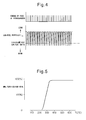
- FIG. 4 shows the feed timing of hydrocarbons from the hydrocarbon feed valve 15 and the change in the air-fuel ratio (A/F)in of the exhaust gas which flows into the exhaust purification catalyst 13.
- the changes in the air-fuel ratio (A/F)in depend on the change in concentration of the hydrocarbons in the exhaust gas which flows into the exhaust purification catalyst 13, so it can be said that the change in the air-fuel ratio (A/F)in shown in FIG. 4 expresses the change in concentration of the hydrocarbons.
- the hydrocarbon concentration becomes higher, the air-fuel ratio (A/F)in becomes smaller, so, in FIG. 4 , the more to the rich side the air-fuel ratio (A/F)in becomes, the higher the hydrocarbon concentration.
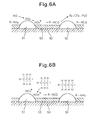
- FIG. 5 shows the NO X purification rate by the exhaust purification catalyst 13 with respect to the catalyst temperatures of the exhaust purification catalyst 13 when periodically making the concentration of hydrocarbons which flow into the exhaust purification catalyst 13 change so as to, as shown in FIG. 4 , make the air-fuel ratio (A/F)in of the exhaust gas flowing to the exhaust purification catalyst 13 change.
- the inventors engaged in research relating to NO X purification for a long time. In the process of research, they learned that if making the concentration of hydrocarbons which flow into the exhaust purification catalyst 13 vibrate by within a predetermined range of amplitude and within a predetermined range of period, as shown in FIG. 5 , an extremely high NO X purification rate is obtained even in a 400°C or higher high temperature region.
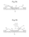
- FIGS. 6A and 6B schematically show the surface part of the catalyst carrier 50 of the exhaust purification catalyst 13.
- FIGS. 6A and 6B show the reaction which is presumed to occur when the concentration of hydrocarbons which flow into the exhaust purification catalyst 13 is made to vibrate by within a predetermined range of amplitude and within a predetermined range of period.
- FIG. 6A shows when the concentration of hydrocarbons which flow into the exhaust purification catalyst 13 is low
- FIG. 6B shows when hydrocarbons are fed from the hydrocarbon feed valve 15 and the concentration of hydrocarbons which flow into the exhaust purification catalyst 13 becomes higher.
- the air-fuel ratio of the exhaust gas which flows into the exhaust purification catalyst 13 is maintained lean except for an instant, so the exhaust gas which flows into the exhaust purification catalyst 13 normally becomes a state of oxygen excess. Therefore, the NO which is contained in the exhaust gas, as shown in FIG. 6A , is oxidized on the platinum 51 and becomes NO 2 . Next, this NO 2 is further oxidized and becomes NO 3 . Further part of the NO 2 becomes NO 2 - . In this case, the amount of production of NO 3 is far greater than the amount of production of NO 2 - . Therefore, on the platinum Pt 51, a large amount of NO 3 and a small amount of NO 2 - are produced. These NO 3 and NO 2 - are strong in activity. Below, these NO 3 and NO 2 - will be referred to as the active NO X *.
- the hydrocarbons are fed from the hydrocarbon feed valve 15, as shown in FIG. 3 , the hydrocarbons are reformed and become radicalized inside of the exhaust purification catalyst 13. As a result, as shown in FIG. 6B , the hydrogen concentration around the active NO X * becomes higher.
- the active NO X * reacts on the platinum 51 with the radical hydrocarbons HC to thereby form the reducing intermediate. This reducing intermediate is adhered or adsorbed on the surface of the basic layer 53.
- the first produced reducing intermediate is considered to be a nitro compound R-NO 2 . If this nitro compound R-NO 2 is produced, the result becomes a nitrile compound R-CN, but this nitrile compound R-CN can only survive for an instant in this state, so immediately becomes an isocyanate compound R-NCO.
- This isocyanate compound R-NCO becomes an amine compound R-NH 2 if hydrolyzed. However, in this case, what is hydrolyzed is considered to be part of the isocyanate compound R-NCO. Therefore, as shown in FIG. 6B , the majority of the reducing intermediate which is held or adsorbed on the surface of the basic layer 53 is believed to be the isocyanate compound R-NCO and amine compound R-NH 2 .
- the active NO X * is absorbed in the basic layer 53 in the form of nitrates without producing a reducing intermediate. To avoid this, it is necessary to make the concentration of hydrocarbons which flow into the exhaust purification catalyst 13 vibrate by within a predetermined range of period.
- the precious metal catalysts 51 and 52 are carried on the exhaust gas flow surface of the exhaust purification catalyst 13.
- a basic exhaust gas flow surface part 54 is formed around the precious metal catalysts 51 and 52.
- NO X is reduced by the reducing action of the reducing intermediate R-NCO or R-NH 2 held on the basic exhaust gas flow surface part 54, and the vibration period of the hydrocarbon concentration is made the vibration period required for continuation of the production of the reducing intermediate R-NCO or R-NH 2 .
- the injection interval is made 3 seconds.
- the vibration period of the hydrocarbon concentration that is, the feed period of the hydrocarbons HC
- the reducing intermediate R-NCO or R-NH 2 disappears from the surface of the basic layer 53.
- the active NO X * which is produced on the platinum Pt 53, as shown in FIG. 7A , diffuses in the basic layer 53 in the form of nitrate ions NO 3 - and becomes nitrates. That is, at this time, the NO X in the exhaust gas is absorbed in the form of nitrates inside of the basic layer 53.
- FIG. 7B shows the case where the air-fuel ratio of the exhaust gas which flows into the exhaust purification catalyst 13 is made the stoichiometric air-fuel ratio or rich when the NO X is absorbed in the form of nitrates inside of the basic layer 53.
- the oxygen concentration in the exhaust gas falls, so the reaction proceeds in the opposite direction (NO 3 - ⁇ NO 2 ) , and consequently the nitrates absorbed in the basic layer 53 become nitrate ions NO 3 - one by one and, as shown in FIG. 7B , are released from the basic layer 53 in the form of NO 2 .
- the released NO 2 is reduced by the hydrocarbons HC and CO contained in the exhaust gas.
- FIG. 8 shows the case of making the air-fuel ratio (A/F)in of the exhaust gas which flows into the exhaust purification catalyst 13 temporarily rich slightly before the NO X absorption ability of the basic layer 53 becomes saturated.
- the time interval of this rich control is 1 minute or more.
- the NO X which was absorbed in the basic layer 53 when the air-fuel ratio (A/F)in of the exhaust gas was lean is released all at once from the basic layer 53 and reduced when the air-fuel ratio (A/F)in of the exhaust gas is made temporarily rich. Therefore, in this case, the basic layer 53 plays the role of an absorbent for temporarily absorbing NO X .
- the basic layer 53 temporarily adsorbs the NO X . Therefore, if using term of storage as a term including both absorption and adsorption, at this time, the basic layer 53 performs the role of an NO X storage agent for temporarily storing the NO X . That is, in this case, if the ratio of the air and fuel (hydrocarbons) which are supplied into the engine intake passage, combustion chambers 2, and exhaust passage upstream of the exhaust purification catalyst 13 is called the air-fuel ratio of the exhaust gas, the exhaust purification catalyst 13 functions as an NO X storage catalyst which stores the NO X when the air-fuel ratio of the exhaust gas is lean and releases the stored NO X when the oxygen concentration in the exhaust gas falls.
- FIG. 9 shows the NO X purification rate when making the exhaust purification catalyst 13 function as an NO X storage catalyst in this way.
- the abscissa of the FIG. 9 shows the catalyst temperature TC of the exhaust purification catalyst 13.
- the catalyst temperature TC is 300°C to 400°C
- an extremely high NO X purification rate is obtained, but when the catalyst temperature TC becomes a 400°C or higher high temperature, the NO X purification rate falls.
- the NO X purification rate falls because if the catalyst temperature TC becomes 400°C or more, the nitrates break down by heat and are released in the form of NO 2 from the exhaust purification catalyst 13. That is, so long as storing NO X in the form of nitrates, when the catalyst temperature TC is high, it is difficult to obtain a high NO X purification rate.
- the new NO X purification method shown from FIG. 4 to FIGS. 6A and 6B as will be understood from FIGS. 6A and 6B , nitrates are not formed or even if formed are extremely small in amount, consequently, as shown in FIG. 5 , even when the catalyst temperature TC is high, a high NO X purification rate is obtained.
- a hydrocarbon feed valve 15 for feeding hydrocarbons is arranged inside of an engine exhaust passage, downstream of the hydrocarbon feed valve 15 inside of the engine exhaust passage, an exhaust purification catalyst 13 for reacting NO X contained in exhaust gas and reformed hydrocarbons is arranged downstream of the hydrocarbon feed valve 15 in the engine exhaust passage, precious metal catalysts 51 and 52 are carried on the exhaust gas flow surface of the exhaust purification catalyst 13, a basic exhaust gas flow surface part 54 is formed around the precious metal catalysts 51 and 52, the exhaust purification catalyst 13 has the property of reducing the NO X which is contained in exhaust gas if the concentration of hydrocarbons which flow into the exhaust purification catalyst 13 is made to vibrate by within a predetermined range of amplitude and within a predetermined range of period and has the property of being increased in storage amount of NO X which is contained in exhaust gas if the vibration period of the hydrocarbon concentration is made longer than this predetermined range, and, at the time of engine operation, the concentration of hydrocarbons which flow into the exhaust purification catalyst 13 is
- the NO X purification method which is shown from FIG. 4 to FIGS. 6A and 6B can be said to be a new NO X purification method designed to remove NO X without forming almost any nitrates in the case of using an exhaust purification catalyst which carries precious metal catalysts and forms a basic layer which can absorb NO X .
- this new NO X purification method when using this new NO X purification method, the nitrates which are detected from the basic layer 53 become much smaller in amount compared with the case where making the exhaust purification catalyst 13 function as an NO X storage catalyst. Note that, this new NO X purification method will be referred to below as the first NO X purification method.
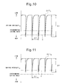
- FIG. 10 shows enlarged the change in the air-fuel ratio (A/F)in shown in FIG. 4 .
- the change in the air-fuel ratio (A/F)in of the exhaust gas which flows into this exhaust purification catalyst 13 simultaneously shows the change in concentration of the hydrocarbons which flow into the exhaust purification catalyst 13.
- ⁇ H shows the amplitude of the change in concentration of hydrocarbons HC which flow into the exhaust purification catalyst 13
- ⁇ T shows the vibration period of the concentration of the hydrocarbons which flow into the exhaust purification catalyst 13.
- (A/F)b shows the base air-fuel ratio which shows the air-fuel ratio of the combustion gas for generating the engine output.
- this base air-fuel ratio (A/F)b shows the air-fuel ratio of the exhaust gas which flows into the exhaust purification catalyst 13 when stopping the feed of hydrocarbons.
- X shows the upper limit of the air-fuel ratio (A/F)in used for producing the reducing intermediate without the produced active NO X * being stored in the form of nitrates inside the basic layer 53 much at all.
- the air-fuel ratio (A/F)in has to be made lower than this upper limit X of the air-fuel ratio.
- X shows the lower limit of the concentration of hydrocarbons required for making the active NO X * and reformed hydrocarbons react to produce a reducing intermediate.
- the concentration of hydrocarbons has to be made higher than this lower limit X.
- whether the reducing intermediate is produced is determined by the ratio of the oxygen concentration and hydrocarbon concentration around the active NO X *, that is, the air-fuel ratio (A/F)in.
- the upper limit X of the air-fuel ratio required for producing the reducing intermediate will below be called the demanded minimum air-fuel ratio.
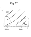
- the demanded minimum air-fuel ratio X is rich, therefore, in this case, to form the reducing intermediate, the air-fuel ratio (A/F)in is instantaneously made the demanded minimum air-fuel ratio X or less, that is, rich.
- the demanded minimum air-fuel ratio X is lean. In this case, the air-fuel ratio (A/F)in is maintained lean while periodically reducing the air-fuel ratio (A/F)in so as to form the reducing intermediate.
- the exhaust purification catalyst 13 determines whether the demanded minimum air-fuel ratio X becomes rich or becomes lean depending on the oxidizing strength of the exhaust purification catalyst 13.
- the exhaust purification catalyst 13 for example, becomes stronger in oxidizing strength if increasing the carried amount of the precious metal 51 and becomes stronger in oxidizing strength if strengthening the acidity. Therefore, the oxidizing strength of the exhaust purification catalyst 13 changes due to the carried amount of the precious metal 51 or the strength of the acidity.
- the demanded minimum air-fuel ratio X has to be reduced the stronger the oxidizing strength of the exhaust purification catalyst 13. In this way the demanded minimum air-fuel ratio X becomes lean or rich due to the oxidizing strength of the exhaust purification catalyst 13.
- the amplitude of the change in concentration of hydrocarbons which flow into the exhaust purification catalyst 13 and the vibration period of the concentration of hydrocarbons which flow into the exhaust purification catalyst 13 will be explained.
- the base air-fuel ratio (A/F)b becomes larger, that is, if the oxygen concentration in the exhaust gas before the hydrocarbons are fed becomes higher, the feed amount of hydrocarbons required for making the air-fuel ratio (A/F)in the demanded minimum air-fuel ratio X or less increases and along with this the excess amount of hydrocarbons which do not contribute to the production of the reducing intermediate also increases.
- the feed amount of hydrocarbons required for making the air-fuel ratio (A/F)in the demanded minimum air-fuel ratio X or less increases and along with this the excess amount of hydrocarbons which do not contribute to the production of the reducing intermediate also increases.
- the NO X well as explained above, it is necessary to make the excess hydrocarbons oxidize. Therefore, to remove the NO X well, the larger the amount of excess hydrocarbons, the larger the amount of oxygen which is required.
- FIG. 13 shows the relationship between the oxygen concentration in the exhaust gas before the hydrocarbons are fed and the amplitude ⁇ H of the hydrocarbon concentration when the same NO X purification rate is obtained.
- the base air-fuel ratio (A/F)b becomes the lowest at the time of an acceleration operation. At this time, if the amplitude ⁇ H of the hydrocarbon concentration is about 200 ppm, it is possible to remove the NO X well.
- the base air-fuel ratio (A/F)b is normally larger than the time of acceleration operation. Therefore, as shown in FIG. 14 , if the amplitude ⁇ H of the hydrocarbon concentration is 200 ppm or more, an excellent NO X purification rate can be obtained.
- the predetermined range of the amplitude of the hydrocarbon concentration is made 200 ppm to 10000 ppm.
- the vibration period ⁇ T of the hydrocarbon concentration becomes longer, the oxygen concentration around the active NO X * becomes higher in the time period after the hydrocarbons are fed to when the hydrocarbons are next fed.
- the vibration period ⁇ T of the hydrocarbon concentration becomes longer than about 5 seconds, the majority of the active NO X * starts to be absorbed in the form of nitrates inside the basic layer 53. Therefore, as shown in FIG. 15 , if the vibration period ⁇ T of the hydrocarbon concentration becomes longer than about 5 seconds, the NO X purification rate falls. Therefore, the vibration period ⁇ T of the hydrocarbon concentration has to be made 5 seconds or less.
- the vibration period of the hydrocarbon concentration is made from 0.3 second to 5 seconds.
- an NO X purification method in the case when making the exhaust purification catalyst 13 function as an NO X storage catalyst will be explained in detail.
- the NO X purification method in the case when making the exhaust purification catalyst 13 function as an NO X storage catalyst in this way will be referred to below as the second NO X purification method.
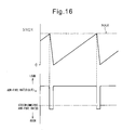
- this second NO X purification method as shown in FIG. 16 , when the stored NO X amount ⁇ NOX of NO X which is stored in the basic layer 53 exceeds a predetermined allowable amount MAX, the air-fuel ratio (A/F)in of the exhaust gas flowing into the exhaust purification catalyst 13 is temporarily made rich. If the air-fuel ratio (A/F)in of the exhaust gas is made rich, the NO X which was stored in the basic layer 53 when the air-fuel ratio (A/F)in of the exhaust gas was lean is released from the basic layer 53 all at once and reduced. Due to this, the NO X is removed.
- the stored NO X amount ⁇ NOX is, for example, calculated from the amount of NO X which is exhausted from the engine.
- the exhausted NO X amount NOXA of NO X which is exhausted from the engine per unit time is stored as a function of the engine output torque Te and engine speed N in the form of a map such as shown in FIG. 17 in advance in the ROM 32.
- the stored NO X amount ⁇ NOX is calculated from the exhausted NO X amount NOXA.
- the period during which the air-fuel ratio (A/F)in of the exhaust gas is made rich is usually 1 minute or more.
- the fuel injector 3 injects additional fuel WR into the combustion chamber 2 in addition to the output generation-use fuel Q so that the air-fuel ratio (A/F)in of the exhaust gas which flows into the exhaust purification catalyst 13 is made rich.
- the abscissa indicates the crank angle.
- This additional fuel WR is injected at a timing at which it will burn, but will not appear as engine output, that is, slightly before ATDC90° after compression top dead center.
- This fuel amount WR is stored as a function of the engine output torque Te and engine speed N in the form of a map such as shown in FIG. 19 in advance in the ROM 32.
- the amplitude ⁇ H and vibration period ⁇ T of the hydrocarbon concentration have to be suitably controlled. That is, to use the first NO X purification method to remove the NO X well, it is necessary to control the amplitude ⁇ H of the hydrocarbon concentration so that the air-fuel ratio (A/F)in of the exhaust gas which flows into the exhaust purification catalyst 13 becomes the demanded minimum air-fuel ratio X or less, and it is necessary to control the vibration period ⁇ T of the hydrocarbon concentration to 0.3 second to 5 seconds.
- the amplitude ⁇ H of the hydrocarbon concentration is controlled by controlling the injection amount of hydrocarbons from the hydrocarbon feed valve 15 and the vibration period ⁇ T of the hydrocarbon concentration is controlled by controlling the injection period of hydrocarbons from the hydrocarbon feed valve 15.
- the injection amount of hydrocarbons from the hydrocarbon feed valve 15 can be controlled by controlling at least one of the injection time or injection pressure of hydrocarbons from the hydrocarbon feed valve 15.
- the present invention will be explained with reference to the case of controlling the injection amount by controlling the injection time while holding the injection pressure constant.
- the optimal opening degree of the throttle valve 10 and the optimal opening degree of the EGR control valve 17 in accordance with the operating state of the engine are found in advance by experiments. Furthermore, the optimal base air-fuel ratio (A/F)b which is obtained when the throttle valve 10 and the EGR control valve 17 are made the optimal opening degrees is also found in advance by experiments.
- FIG. 20A shows the optimal base air-fuel ratio (A/F)b which is found by experiments as a function of the engine speed N and engine output torque Te. Note that, the solid lines in FIG. 20A express the equivalent air-fuel ratio lines of the air-fuel ratios shown by the numerical values.
- the fuel injection amount from the fuel injector 3 is controlled so that the air-fuel ratio of the exhaust gas which is exhausted from the engine becomes the optimal base air-fuel ratio (A/F)b which is shown in FIG. 20A .
- the optimal base air-fuel ratio (A/F)b which is shown in FIG. 20A is stored as a function of the engine speed N and engine output torque Te in the form of a map such as shown in FIG. 20B in advance in the ROM 32.
- FIG. 21A shows the optimal hydrocarbon injection period ⁇ T which is found by experiments as a function of the engine speed N and the engine output torque Te. Note that, the solid lines in FIG. 21A show the equivalent hydrocarbon injection periods. As will be understood from FIG. 21A , the optimal hydrocarbon injection period ⁇ T becomes shorter the lower the engine speed N and becomes shorter the higher the engine output torque Te.
- the optimal hydrocarbon injection period ⁇ T which is shown in FIG. 21A is stored as a function of the engine speed N and the engine output torque Te in the form of a map such as shown in FIG. 21B in advance in the ROM 32. Further, the optimal hydrocarbon injection period WT which is found by experiments is also stored as a function of the engine speed N and engine output torque Te in the form of a map such as shown in FIG. 20C in advance in the ROM 32.
- FIG. 22A shows a change of the air-fuel ratio (A/F)in of the exhaust gas which flows into the exhaust purification catalyst 13 when the hydrocarbon injection period is made the optimal hydrocarbon injection period ⁇ T which is shown in FIG. 21B and the hydrocarbon injection period is made the optimal hydrocarbon injection period WT which is shown in FIG. 21C
- FIG. 22B shows a change in the air-fuel ratio which is detected by the downstream side air-fuel ratio sensor 24 at this time.
- a rich side peak air-fuel ratio (A/F)r of the air-fuel ratio (A/F)in of the exhaust gas which flows into the exhaust purification catalyst 13 becomes rich, while a rich side peak air-fuel ratio (A/F)p of the air-fuel ratio which is detected by the downstream side air-fuel ratio sensor 24 becomes lean.
- A/F rich side peak air-fuel ratio
- A/F rich side peak air-fuel ratio
- the rich side peak air-fuel ratio (A/F)p which is detected by the downstream side air-fuel ratio sensor 24 when the hydrocarbon injection period is made the optimal hydrocarbon injection period ⁇ T which is shown in FIG. 21B and the hydrocarbon injection period is made the optimal hydrocarbon injection period WT which is shown in FIG. 21C is found in advance by experiments.
- the rich side peak air-fuel ratio (A/F)p which is found in advance by experiments is stored in advance as the target peak air-fuel ratio (A/F)t with respect to the different engine operating states.
- this target peak air-fuel ratio (A/F)t is stored as a function of the engine speed N and engine output torque Te in the form of a map as shown in FIG. 23 in advance in the ROM 32.
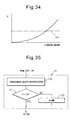
- FIG. 24 schematically shows the relationship between the output current I of the air-fuel ratio sensors 23 and 24 and the air-fuel ratio. From FIG. 24 , it will be understood that the output current I of the air-fuel ratio sensors 23 and 24 changes in accordance with the air-fuel ratio and therefore it is possible to detect the air-fuel ratio from the output current I of the air-fuel ratio sensors 23 and 24.
- the hydrocarbon injection period deviates from the optimal hydrocarbon injection period WT which is shown in FIG. 21C , the rich side peak air-fuel ratio (A/F)p of the air-fuel ratio which is detected by the downstream side air-fuel ratio sensor 24 also deviates from the target peak air-fuel ratio (A/F)t which is shown in FIG. 23 .
- the hydrocarbon injection period becomes the optimal hydrocarbon injection period WT which is shown in FIG. 21C and as a result the maximum NO X purification rate can be secured.
- the downstream side air-fuel ratio sensor 24 for detecting the air-fuel ratio of the exhaust gas is arranged in the engine exhaust passage downstream of the exhaust purification catalyst 13, and the injection amount of hydrocarbons from the hydrocarbon feed valve 15 is controlled based on the output signal of the downstream side air-fuel ratio sensor 24 so that the amplitude of the change in concentration of hydrocarbons which flows into the exhaust purification catalyst 13 becomes within a predetermined range of amplitude.
- the injection amount of hydrocarbons from the hydrocarbon feed valve 15 is made to increase, while when the rich side peak air-fuel ratio (A/F)p which is detected by the downstream side air-fuel ratio sensor 24 becomes the rich side from the predetermined air-fuel ratio (A/F)t, the injection amount of hydrocarbons from the hydrocarbon feed valve 15 is made to decrease,
- this routine is executed by interruption every a fixed time period.
- step 60 it is judged from the output signal of the temperature sensor 25 if a temperature TC of the exhaust purification catalyst 13 exceeds an activation temperature TCo.
- TC ⁇ TCo that is, when the exhaust purification catalyst 13 is not activated, it is judged that the second NO X purification method should be used, then the routine proceeds to step 61.
- the NO X amount NOXA exhausted per unit time is calculated from the map which is shown in FIG. 17 .
- step 62 the exhausted NO X amount NOXA is added to the ⁇ NOX so as to calculate the stored NO X amount ⁇ NOX.
- step 63 it is judged if the stored NO X amount ⁇ NOX exceeds the allowable value MAX.
- step 64 processing is performed for injecting fuel from the fuel injector 3. At this time, fuel is injected from the fuel injector 3 so as to give a predetermined lean air-fuel ratio which is determined from the operating state of the engine.
- step 65 the rich control I is performed. That is, the additional fuel amount WR is calculated from the map which is shown in FIG. 19 and the injection action of additional fuel is performed. At this time, the stored NO X is released from the exhaust purification catalyst 13.
- step 66 ⁇ NOX is cleared.
- step 60 when it is judged at step 60 that TC ⁇ TCo, that is, when the exhaust purification catalyst 13 is activated, the routine proceeds to step 67 where it is judged if TC ⁇ TCo at the time of the previous interruption.
- step 68 the rich control II is performed.
- the additional fuel amount WR is calculated from the map which is shown in FIG. 19 , the action of injection of the additional fuel is performed, and the stored NO X is released from the exhaust purification catalyst 13.
- step 69 ⁇ NOX is cleared.
- step 70 the routine proceeds to step 70 where the operational control I is performed.
- an NO X purification action is performed by the first NO X purification method according to the present invention. That is, when the exhaust purification catalyst 13 is not activated, an NO X purification action is performed by the second NO X purification method. If the exhaust purification catalyst 13 is activated, the second NO X purification method is switched to the first NO X purification method.
- the second NO X purification method is switched to the first NO X purification method, if the exhaust purification catalyst 13 stores NO X , the NO X which is stored from the exhaust purification catalyst 13 is released all at once without being reduced. Therefore, in the example which is shown in FIG. 25 , to stop the NO X which is stored from the exhaust purification catalyst 13 in this way being released all at once without being reduced, right before the second NO X purification method is switched to the first NO X purification method, at step 68, the rich control II is performed for releasing the stored NO X from the exhaust purification catalyst 13 by the second NO X purification method.
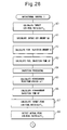
- FIG. 26 and FIG. 27 show a first embodiment of this operational control I.
- the target value of the base air-fuel ratio that is, the target air-fuel ratio (A/F)b
- the intake air amount GA is calculated from the output signal of the intake air amount detector 8.
- the fuel injection amount Q for generation of output from the fuel injector 3 which is required for making the base air-fuel ratio the target air-fuel ratio (A/F)b is calculated from the target air-fuel ratio (A/F)b and the intake air amount GA.
- the fuel injection time QT is calculated from this fuel injection amount Q
- fuel injection processing is performed to inject fuel from the fuel injector 3 in accordance with this fuel injection time QT.
- the optimal hydrocarbon injection period ⁇ T is calculated from the map which is shown in FIG. 21B .
- the optimal hydrocarbon injection period WT is calculated from the map which is shown in FIG. 21C .
- the target peak air-fuel ratio (A/F)t is calculated from the map which is shown in FIG. 23 .
- the actual rich side peak air-fuel ratio (A/F)p is detected from the output of the downstream side air-fuel ratio sensor 24.
- step 89 it is judged if the actual rich side peak air-fuel ratio (A/F)p is larger than the value of the target peak air-fuel ratio (A/F)t plus a small constant value ⁇ .
- the routine proceeds to step 90 where a constant value ⁇ K is added to the correction coefficient K for the hydrocarbon injection period WT.
- the routine proceeds to step 93 where a hydrocarbon injection period WT multiplied with the correction coefficient K (K ⁇ WT) is made the final hydrocarbon injection period WTO.
- step 89 when it is judged at step 89 that (A/F)p>(A/F)t+ ⁇ does not stand, the routine proceeds to step 91 where it is judged if the actual rich side peak air-fuel ratio (A/F)p is smaller than the target peak air-fuel ratio (A/F)t minus the constant value ⁇ .
- step 92 the correction coefficient K is reduced by the constant value ⁇ K whereupon the routine proceeds to step 93.
- step 94 hydrogen injection processing is performed to inject hydrocarbons from the hydrocarbon feed valve 15 in accordance with the final hydrocarbon injection period WTO.
- the fuel injection amount Q for generation of output which is required for making the base air-fuel ratio the target air-fuel ratio (A/F)b is calculated based on the intake air amount GA which is detected by the intake air detector 8, then the fuel injection time QT is calculated from this fuel injection amount Q.
- the base air-fuel ratio is held at the target air-fuel ratio (A/F)b.
- the base air-fuel ratio will no longer match the target air-fuel ratio (A/F)b.
- the downstream side air-fuel ratio sensor 24 is used to make the actual rich side peak air-fuel ratio (A/F)p the target peak air-fuel ratio (A/F)t by feedback control of the hydrocarbon feed amount.
- the actual rich side peak air-fuel ratio (A/F)p is controlled to become the target peak air-fuel ratio (A/F)t. That is, in the first embodiment of this operational control I, even if the base air-fuel ratio deviates, the actual rich side peak air-fuel ratio (A/F)p is controlled to become the target peak air-fuel ratio (A/F)t.
- the rich side peak air-fuel ratio (A/F)r of the air-fuel ratio (A/F)in of the exhaust gas flowing into the exhaust purification catalyst 13, which gives the highest NO X purification rate is determined with respect to the base air-fuel ratio.
- This rich side peak air-fuel ratio (A/F)r which gives the highest NO X purification rate changes commensurately if the base air-fuel ratio changes. Therefore, when the base air-fuel ratio deviates from the target air-fuel ratio (A/F)b, the base air-fuel ratio is preferably returned to the target air-fuel ratio (A/F)b.
- the upstream side air-fuel ratio sensor 23 is used to control the base air-fuel ratio to the target air-fuel ratio (A/F)b. That is, in the second embodiment of this operational control I, the air-fuel ratio of the exhaust gas which is exhausted from the engine is detected by the upstream side air-fuel ratio sensor 23, and the fuel injection time QT from the fuel injector 3 is corrected so that the detected air-fuel ratio becomes the target air-fuel ratio (A/F)b. If using the upstream side air-fuel ratio sensor 23 in this way, even if the intake air amount detector 8 deteriorates, the base air-fuel ratio can be maintained at the target air-fuel ratio (A/F)b.
- FIG. 28 and FIG. 29 show the routine for working the second embodiment of this operational control I. Note that, in the routine which is shown in FIG. 28 and FIG. 29 , steps 100 to 103 are the same as steps 80 to 83 of FIG. 26 . In the routine which is shown in FIG. 28 and FIG. 29 , steps 111 and 120 are the same as steps 85 to 94 of FIG. 26 and FIG. 27 .
- the target value of the base air-fuel ratio that is, the target air-fuel ratio (A/F)b
- the intake air amount GA is calculated from the output signal of the intake air amount detector 8.
- the fuel injection amount Q for output generation from the fuel injector 3 which is required for making the base air-fuel ratio the target air-fuel ratio (A/F)b is calculated.
- the fuel injection time QT is calculated from this fuel injection amount Q.
- step 104 the output of the upstream side air-fuel ratio sensor 23 is used as the basis to detect the actual air-fuel ratio (A/F)a of the exhaust gas which is exhausted from the engine.
- step 105 it is judged if the actual air-fuel ratio (A/F)a is larger than the target air-fuel ratio (A/F)b plus a small constant value ⁇ .
- the routine proceeds to step 106 where the correction coefficient G for the fuel injection time QT is increased by a constant value ⁇ G.
- the routine proceeds to step 106 where the fuel injection time QT multiplied with the correction coefficient G, that is, the value (G ⁇ QT), is made the final fuel injection time QTO.
- step 105 when it is judged at step 105 that (A/F)a>(A/F)b+ ⁇ does not stand, the routine proceeds to step 107 where it is judged if the actual air-fuel ratio (A/F)a of the exhaust gas which is exhausted from the engine is smaller than the target peak air-fuel ratio (A/F)b minus a constant value ⁇ .
- step 108 the routine proceeds to step 108 where the correction coefficient G is reduced by a constant value ⁇ G, then the routine proceeds to step 109.
- step 110 processing is performed to inject fuel from the fuel injector 3 in accordance with the fuel injection time QTO.
- the optimal hydrocarbon injection period ⁇ T is calculated from the map which is shown in FIG. 21B .
- the optimal hydrocarbon injection period WT is calculated from the map which is shown in FIG. 21C .
- the target peak air-fuel ratio (A/F)t is calculated from the map which is shown in FIG. 23 .
- the actual rich side peak air-fuel ratio (A/F)p is detected from the output of the downstream side air-fuel ratio sensor 24.
- step 115 it is judged if the actual rich side peak air-fuel ratio (A/F)p is larger than the target peak air-fuel ratio (A/F)t plus a small constant value ⁇ .
- the routine proceeds to step 116 where the correction coefficient K for the hydrocarbon injection period WT is increased by a constant value ⁇ K.
- the routine proceeds to step 119 where the hydrocarbon injection period WT multiplied with the correction coefficient K, that is, the value (K ⁇ WT), is made the final hydrocarbon injection period WTO.
- step 115 when it is judged at step 115 that (A/F)p>(A/F)t+ ⁇ does not stand, the routine proceeds to step 117 where it is judged if the actual rich side peak air-fuel ratio (A/F)p is smaller than the target peak air-fuel ratio (A/F)t minus a constant value ⁇ .
- step 118 the correction coefficient K is reduced by a constant value ⁇ K, then the routine proceeds to step 119.
- step 120 hydrocarbon injection processing is performed for injecting hydrocarbons from the hydrocarbon feed valve 15 in accordance with the final hydrocarbon injection period WTO.
- the injection amount of hydrocarbons from the hydrocarbon feed valve 15 is controlled so that the amplitude of the change in concentration of hydrocarbons which flow into the exhaust purification catalyst 13 becomes within a predetermined range of amplitude.
- the amount of fuel which is fed to the engine combustion chamber 2 is controlled based on the output signal of the upstream side air-fuel ratio sensor 23 so that the air-fuel ratio of the exhaust gas which is exhausted from the engine, that is, the base air-fuel ratio, becomes a predetermined air-fuel ratio, that is, the target air-fuel ratio (A/F)b.
- the rich side peak air-fuel ratio (A/F)p of the exhaust gas which flows out from the exhaust purification catalyst 13 is controlled to become the target peak air-fuel ratio (A/F)t.
- the actual air-fuel ratio (A/F)a which is detected by the upstream side air-fuel ratio sensor 23 and the actual rich side peak air-fuel ratio (A/F)p which is detected by the downstream side air-fuel ratio sensor 24 are used to calculate the hydrocarbon injection period WTO from the hydrocarbon feed valve 15 from the difference between the actual air-fuel ratio (A/F)a which is detected by the upstream side air-fuel ratio sensor 23 and the target air-fuel ratio (A/F)b and the difference of the actual rich side peak air-fuel ratio (A/F)p which is detected from the downstream side air-fuel ratio sensor 24 and the target peak air-fuel ratio (A/F)t on the basis of the following formula.
- WT is the hydrocarbon injection period from the hydrocarbon feed valve 15 which is calculated from the map of FIG. 21C
- K1 and K2 are positive constants.
- the injection amount of hydrocarbons from the hydrocarbon feed valve 15 is increased, while when the rich side peak air-fuel ratio which is detected by the downstream side air-fuel ratio sensor 24 is at the rich side from the predetermined air-fuel ratio, the injection amount of hydrocarbons from the hydrocarbon feed valve 15 is made to decrease.
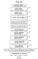
- FIG. 30 shows the routine of the third embodiment of the operational control I which is performed at step 70 of FIG. 25 .
- the target value of the base air-fuel ratio that is, the target air-fuel ratio (A/F)b
- the upstream side air-fuel ratio sensor 23 is used to detect the actual air-fuel ratio (A/F)a of the exhaust gas which is exhausted from the engine.
- the intake air amount GA is calculated from the output signal of the intake air amount detector 8.
- the fuel injection amount Q for generation of output from the fuel injector 3 which is required for making the base air-fuel ratio the target air-fuel ratio (A/F)b is calculated from the target air-fuel ratio (A/F)b and the intake air amount GA.
- the fuel injection time QT is calculated from this fuel injection amount Q, next, at step 135, fuel injection processing is performed to inject fuel from the fuel injector 3 in accordance with this fuel injection time QT.
- the optimal hydrocarbon injection period ⁇ T is calculated from the map which is shown in FIG. 21B .
- the optimal hydrocarbon injection period WT is calculated from the map which is shown in FIG. 21C .
- the target peak air-fuel ratio (A/F)t is calculated from the map which is shown in FIG. 23 .
- the actual rich side peak air-fuel ratio (A/F)p is detected from the output of the downstream side air-fuel ratio sensor 24.
- the hydrocarbon injection period WTO from the hydrocarbon feed valve 15 is calculated based on the following formula. WTO ⁇ WT ⁇ 1 + K ⁇ 1 ⁇ A / F ⁇ a - A / F ⁇ b + K ⁇ 2 ⁇ A / F ⁇ p - A / F ⁇ t
- step 141 hydrocarbon injection processing is performed to inject hydrocarbons from the hydrocarbon feed valve 15 in accordance with the calculated hydrocarbon injection period WTO.
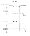
- FIG. 31 shows the changes in the air-fuel ratio of the exhaust gas (A/F)a which flows into the exhaust purification system 13 and the changes in the air-fuel ratio of the exhaust gas (A/F)c which is exhausted from the exhaust purification system 13 when this rich control II is performed.
- the time period trt where the air-fuel ratio of the inflowing exhaust gas (A/F)a is made rich is several seconds. This time period trt is made to change in accordance with the amount of the stored NO X .
- (A/F)rt shows the target rich air-fuel ratio when rich control II is performed.
- the additional fuel amount WR fed into the combustion chamber 2 is controlled by learning each time rich control II is performed so that the actual air-fuel ratio (A/F)a which is detected by the upstream side air-fuel ratio sensor 23 becomes the target rich air-fuel ratio (A/F) rt.
- the exhaust purification system 13 has the ability to store oxygen in the catalyst.
- the exhaust purification system 13 has an oxygen storing ability
- the air-fuel ratio of the inflowing exhaust gas (A/F)a is made rich
- the excessive hydrocarbons in the exhaust gas react with the stored oxygen and are oxidized.
- the air-fuel ratio of the discharged exhaust gas (A/F)c is maintained at the stoichiometric air-fuel ratio as shown by the time period ts of FIG. 31 .
- the exhaust purification system 13 deteriorates, the oxygen storing ability falls.
- the time period ts during which the air-fuel ratio of the exhaust gas (A/F)c which is exhausted is maintained at the stoichiometric air-fuel ratio becomes shorter. Therefore, it is possible to detect that the exhaust purification system 13 has deteriorated by the time period ts during which the air-fuel ratio of the exhaust gas (A/F)c which is discharged is maintained at the stoichiometric air-fuel ratio becoming shorter.
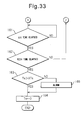
- FIG. 32 and FIG. 33 which show this rich control II will be explained.
- step 150 the fuel injection amount Q for generation of output which is shown in FIG. 18 is calculated and the additional fuel amount WR is calculated from the map which is shown in FIG. 19 .
- step 151 the actual air-fuel ratio of the inflowing exhaust gas (A/F)a is detected by the upstream side air-fuel ratio sensor 23.
- step 152 it is judged if the air-fuel ratio of the inflowing exhaust gas (A/F)a is larger than the target rich air-fuel ratio (A/F)rt plus a small constant value d.
- step 153 the routine proceeds to step 153 where the constant value ⁇ GR is added to the learned value GR for the additional fuel amount WR.
- step 156 the routine proceeds to step 156 where the additional fuel amount WR multiplied with the learned value GR (GR ⁇ WR) is made the final additional fuel amount WRO.
- step 152 when it is judged at step 152 that (A/F)a>(A/F)rt+d does not stand, the routine proceeds to step 154 where it is judged if the actual air-fuel ratio of the inflowing exhaust gas (A/F)a is smaller than the target peak air-fuel ratio (A/F)rt minus a constant value ⁇ .
- step 155 When (A/F)a ⁇ (A/F)rt-d, the routine proceeds to step 155 where a constant value ⁇ GR is subtracted from the learned value GR, then the routine proceeds to step 156.
- step 157 fuel injection processing is performed to inject the additional fuel WRO in addition to the fuel injection amount Q from the fuel injector 3 in accordance with the final additional fuel amount WRO.
- step 158 the actual air-fuel ratio of the discharged exhaust gas (A/F)c is detected by the downstream side air-fuel ratio sensor 24.
- step 159 it is judged if the actual air-fuel ratio of the discharged exhaust gas (A/F)c is smaller than the stoichiometric air-fuel ratio plus a small constant value h and is larger than the stoichiometric air-fuel ratio minus the constant value h, that is, the air-fuel ratio of the exhausted exhaust gas (A/F)c, is about the stoichiometric air-fuel ratio.
- step 160 When the air-fuel ratio of the exhausted exhaust gas (A/F)c is about the stoichiometric air-fuel ratio, the routine proceeds to step 160 where a fixed time ⁇ t is added to the stoichiometric air-fuel ratio duration Ts.
- step 161 the ⁇ t time is waited, then the routine proceeds to step 162 where it is judged if the rich time which is shown by trt in FIG. 31 has elapsed.
- the routine returns to step 150. That is, until the rich time elapses, the routine returns to step 150 every ⁇ t time.
- the routine proceeds to step 163 where it is judged if the stoichiometric air-fuel ratio duration Ts is longer than the deterioration judgment reference time XTs.
- the base air-fuel ratio is controlled based on the output signal of the upstream side air-fuel ratio sensor 23 so as to be maintained at the target air-fuel ratio (A/F)b.
- the output signal of the downstream side air-fuel ratio sensor 24 is used as the basis so that the rich side peak air-fuel ratio (A/F)r of the air-fuel ratio (A/F)in of the exhaust gas which flows into the exhaust purification catalyst 13 is accurately controlled to the target air-fuel ratio (A/F)b, so a high NO X purification rate can be obtained.
- the base air-fuel ratio is maintained at the target air-fuel ratio (A/F)b and the rich side peak air-fuel ratio (A/F)r of the air-fuel ratio (A/F)in of the exhaust gas which flows into the exhaust purification catalyst 13 is accurately controlled to the target air-fuel ratio (A/F)b in this way, if an abnormality occurs in the exhaust purification system, for example, if an abnormality occurs in the hydrocarbon feed action of the hydrocarbon feed valve 15, the effect of that abnormality appears quickly in the output signal of the downstream side air-fuel ratio sensor 24.
- the output signal of the downstream side air-fuel ratio sensor 24 is used as the basis for performing the diagnosis of the trouble of the exhaust purification system.
- the hydrocarbon feed valve 15 becomes clogged, the feed amount of hydrocarbons from the hydrocarbon feed valve 15 is decreased. Therefore, when the base air-fuel ratio is maintained at the target air-fuel ratio (A/F)b and the rich side peak air-fuel ratio (A/F)r of the air-fuel ratio (A/F)in of the exhaust gas which flows into the exhaust purification catalyst 13 is accurately controlled to the target air-fuel ratio (A/F)b, that is, when the second embodiment of operational control I which is shown in FIG. 28 and FIG. 29 is being performed, if the hydrocarbon feed valve 15 is clogged and the feed amount of hydrocarbons from the hydrocarbon feed valve 15 is decreased, the correction coefficient K which is shown in steps 116, 118, and 119 of FIG. 29 is made to increase to make the rich side peak air-fuel ratio (A/F)r of the air-fuel ratio (A/F)in of the exhaust gas which flows into the exhaust purification catalyst 13 match the target air-fuel ratio (A/F)b.
- the value of the correction coefficient K when the amount of clogging of the hydrocarbon feed valve 15 becomes over an allowable amount is stored as a limit value XK in advance. When the value of the correction coefficient K exceeds this limit value XK, an alarm is issued showing that the hydrocarbon feed valve 15 has become clogged.
- FIG. 36A shows the change in the air-fuel ratio which is detected by the downstream side air-fuel ratio sensor 24 when the NO X purification action by the first NO X purification method is being performed.
- the air-fuel ratio which is detected by the downstream side air-fuel ratio sensor 24 usually, as shown in I of FIG. 36 , vibrates to the rich side from the base air-fuel ratio (A/F)b. That is, when the injection period of hydrocarbons from the hydrocarbon feed valve 15 is controlled so that the concentration of hydrocarbons which flow into the exhaust purification catalyst 13 vibrates by within a predetermined range of period, the air-fuel ratio which is detected by the downstream side air-fuel ratio sensor 24 usually vibrates to the rich side from the base air-fuel ratio (A/F)b.
- the area S of the part which is shown by hatching that is, the integrated value of the difference between the air-fuel ratio which is detected by the downstream side air-fuel ratio sensor 24 and the base air-fuel ratio (A/F)b, expresses the actual injection amount of hydrocarbons per injection from the hydrocarbon feed valve 15. Note that, the above-mentioned area S and integrated value show the area S and integrated value per fluctuation of the air-fuel ratio. This same is true below as well.
- This area S can be calculated from the target injection amount of hydrocarbons which is calculated in accordance with the operating state of the engine.
- the surface area S which is calculated from the target injection amount in this way is called the reference area So.
- the area S becomes equal to the reference area So.
- the area S will not become equal to the reference area So. For example, when the actually injected injection amount is smaller compared with the target injection amount, the area S becomes smaller than the reference area So.
- the hydrocarbon feed valve 15 it is judged if hydrocarbons are being normally injected from the hydrocarbon feed valve 15, for example, if the hydrocarbon feed valve 15 is clogged on the basis of the integrated value of the difference between the air-fuel ratio detected by the downstream side air-fuel ratio sensor 24 and the base air-fuel ratio (A/F)b.
- the hydrocarbon feed valve 15 when the area S becomes smaller than the reference area So multiplied with a constant value C ( ⁇ 1.0), that is, the value C ⁇ So, it is judged that the hydrocarbon feed valve 15 is clogged.
- the air-fuel ratio which is detected by the downstream side air-fuel ratio sensor 24 changes toward the rich side before returning to the base air-fuel ratio (A/F)b due to the next injection action of hydrocarbons. If the air-fuel ratio which is detected by the downstream side air-fuel ratio sensor 24 no longer returns to the base air-fuel ratio (A/F)b in this way, the calculated surface area S no longer will express the actual hydrocarbon injection amount.
- the air-fuel ratio which is detected by the downstream side air-fuel ratio sensor 24 when the air-fuel ratio which is detected by the downstream side air-fuel ratio sensor 24 no longer returns to the base air-fuel ratio (A/F)b, the air-fuel ratio which is detected by the downstream side air-fuel ratio sensor 24 is made to return to the base air-fuel ratio (A/F)b by, as shown by II in FIG. 36B , lengthening the injection period of hydrocarbons from the hydrocarbon feed valve 15.
- the injection period of hydrocarbons is too short for accurately detecting the injection amount of hydrocarbons from the hydrocarbon feed valve 15, the injection period of hydrocarbons is made longer. Further, in this case, the amount of hydrocarbons which is supplied is prevented from becoming insufficient by increasing the injection amount of hydrocarbons per injection from the hydrocarbon feed valve 15.
- the injection amount of hydrocarbons from the hydrocarbon feed valve 15 can no longer be accurately detected. Therefore, in the embodiment according to the present invention, as shown by I in FIG. 36C , to prevent hydrocarbons from passing straight through the exhaust purification catalyst 13 when the injection amount of hydrocarbons per injection from the hydrocarbon feed valve 15 is large, as shown by II in FIG. 36C , the injection amount of hydrocarbons per injection from the hydrocarbon feed valve 15 is reduced.
- the injection amount of hydrocarbons when using the integrated value of the difference between the air-fuel ratio detected by the downstream side air-fuel ratio sensor 24 and the base air-fuel ratio (A/F)b as the basis to judge if the hydrocarbon feed valve 15 is clogged, if the injection amount of hydrocarbons becomes too great for accurately detecting the injection amount of hydrocarbons from the hydrocarbon feed valve 15, the injection amount of hydrocarbons is made smaller.
- step 170 it is judged if the timing is one for trouble diagnosis.
- step 173 processing is performed for injecting hydrocarbons from the hydrocarbon feed valve 15.
- step 171 it is judged if the operating state of the engine is in the operating region A which is shown in FIG. 37 .
- step 172 it is judged if the operating state of the engine is in the operating region B which is shown in FIG. 37 .
- the routine proceeds to step 173.
- step 171 when it is judged at step 171 that the operating state of the engine is in the operating region A which is shown in FIG. 37 , the routine proceeds to step 174 where the injection period of hydrocarbons ⁇ T from the hydrocarbon feed valve 15 is multiplied with a predetermined correction value F (>1.0).
- step 175 the hydrocarbon injection period WTO from the hydrocarbon feed valve 15 which was calculated at step 119 of FIG. 29 is multiplied with the correction value F.
- step 173 At this time, the injection period of hydrocarbons from the hydrocarbon feed valve 15 is lengthened and the injection amount of hydrocarbons per injection is increased.
- step 172 when, at step 172, it is judged that the operating state of the engine is the operating region B which is shown in FIG. 37 , the routine proceeds to step 176 where the hydrocarbon injection period WTO from the hydrocarbon feed valve 15 which was calculated at step 119 of FIG. 29 is multiplied with a correction value J ( ⁇ 1.0). Next, the routine proceeds to step 173. At this time, the injection amount of hydrocarbons each injection from the hydrocarbon feed valve 15 is made to decrease.
- step 177 the integral value of the difference between the air-fuel ratio detected by the downstream side air-fuel ratio sensor 24 and the base air-fuel ratio (A/F) b , that is, the area S per fluctuation of the air-fuel ratio which is shown in FIG. 36A , is calculated.
- step 178 the reference area So is calculated from the target injection amount of hydrocarbons.
- step 179 it is judged if the area S is larger than the reference area So multiplied with the constant value C ( ⁇ 1.0), that is, the value C ⁇ S 0 .
- the routine proceeds to step 180 where an alarm is issued.
- an oxidation catalyst for reforming the hydrocarbons in the engine exhaust passage upstream of the exhaust purification catalyst 13, an oxidation catalyst for reforming the hydrocarbons can be arranged.
Abstract
Description
- The present invention relates to an exhaust purification system of an internal combustion engine.
- Known in the art is an internal combustion engine which arranges, in an engine exhaust passage, an NOX storage catalyst which stores NOX which is contained in exhaust gas when the air-fuel ratio of the inflowing exhaust gas is lean and which releases the stored NOX when the air-fuel ratio of the inflowing exhaust gas becomes rich, which arranges a fuel addition valve in the engine exhaust passage upstream of the NOX storage catalyst, which arranges an air-fuel ratio sensor inside the engine exhaust passage downstream of the NOX storage catalyst, and which feeds fuel from the fuel addition valve to the inside of the engine exhaust passage to make the air-fuel ratio of the exhaust gas flowing into the NOX storage catalyst rich when NOX should be released from the NOX storage catalyst (for example, see Patent Literature 1).
- In this regard, in this internal combustion engine, for example, if the fuel addition valve becomes clogged, the amount of fuel feed when feeding fuel from the fuel addition valve to release NOX becomes smaller compared with the amount of fuel feed when the fuel addition valve is not clogged. As a result, at this time, the air-fuel ratio of the exhaust gas which flows out from the NOX storage catalyst becomes the lean side compared with the air-fuel ratio when the fuel addition valve is not clogged. Therefore, in this internal combustion engine, the air-fuel ratio of the exhaust gas when fuel is fed from the fuel addition valve for release of NOX is detected by the air-fuel ratio sensor. When the air-fuel ratio of the exhaust gas which is detected by the air-fuel ratio sensor becomes the lean side compared with the air-fuel ratio when the fuel addition valve is not clogged, it is judged that there is an abnormality in the fuel addition valve.
-
- Patent Literature 1: Japanese Patent Publication (A) No.
2009-221939 - However, if this NOX storage catalyst becomes a high temperature, the NOX purification rate ends up falling. Therefore, there is the problem that if the NOX storage catalyst becomes a high temperature, a high NOX purification rate cannot be obtained.
- An object of the present invention is to provide an exhaust purification system of an internal combustion engine which can give a high NOX purification rate even when the exhaust purification catalyst becomes a high temperature.
- According to the present invention, there is provided an exhaust purification system of an internal combustion engine in which a hydrocarbon feed valve for feeding hydrocarbons is arranged in an engine exhaust passage, an exhaust purification catalyst for reacting NOX contained in exhaust gas and reformed hydrocarbons is arranged in the engine exhaust passage downstream of the hydrocarbon feed valve, a downstream side air-fuel ratio sensor for detecting an air-fuel ratio of the exhaust gas is arranged in the engine exhaust passage downstream of the exhaust purification catalyst, precious metal catalysts are carried on an exhaust gas flow surface of the exhaust purification catalyst and a basic exhaust gas flow surface part is formed around the precious metal catalysts, the exhaust purification catalyst has a property of reducing the NOX which is contained in exhaust gas if a concentration of hydrocarbons which flow into the exhaust purification catalyst is made to vibrate by within a predetermined range of amplitude and within a predetermined range of period and has a property of being increased in storage amount of NOX which is contained in exhaust gas if the vibration period of the hydrocarbon concentration is made longer than the predetermined range, at the time of engine operation, the concentration of hydrocarbons which flow into the exhaust purification catalyst is made to vibrate with the predetermined range of period by control of an injection period of hydrocarbons from the hydrocarbon feed valve, and the amplitude of the change of concentration of hydrocarbons which flow into the exhaust purification catalyst is made to become within the predetermined range of amplitude by control of an injection amount of hydrocarbons from the hydrocarbon feed valve based on an output signal of the downstream side air-fuel ratio sensor.
- It is possible to obtain a high NOX purification rate even if the exhaust purification catalyst becomes a high temperature.
-
-
FIG. 1 is an overall view of a compression ignition type internal combustion engine. -
FIG. 2 is a view which schematically shows a surface part of a catalyst carrier. -
FIG. 3 is a view for explaining an oxidation reaction in an exhaust purification catalyst. -
FIG. 4 is a view which shows a change of an air-fuel ratio of exhaust gas flowing into an exhaust purification catalyst. -
FIG. 5 is a view which shows an NOX purification rate. -
FIG. 6A and 6B are views for explaining an oxidation reduction reaction in an exhaust purification catalyst. -
FIG. 7A and 7B are views for explaining an oxidation reduction reaction in an exhaust purification catalyst. -
FIG. 8 is a view which shows a change of an air-fuel ratio of exhaust gas flowing into an exhaust purification catalyst. -
FIG. 9 is a view of an NOX purification rate. -
FIG. 10 is a time chart which shows a change of an air-fuel ratio of exhaust gas flowing into an exhaust purification catalyst. -
FIG. 11 is a time chart which shows a change of an air-fuel ratio of exhaust gas flowing into an exhaust purification catalyst. -
FIG. 12 is a view which shows a relationship between an oxidizing strength of an exhaust purification catalyst and a demanded minimum air-fuel ratio X. -
FIG. 13 is a view which shows a relationship between an oxygen concentration in exhaust gas and an amplitude ΔH of a hydrocarbon concentration giving the same NOX purification rate. -
FIG. 14 is a view which shows a relationship between an amplitude ΔH of a hydrocarbon concentration and an NOX purification rate. -
FIG. 15 is a view which shows a relationship of a vibration period ΔT of a hydrocarbon concentration and an NOX purification rate. -
FIG. 16 is a view which shows a change in the air-fuel ratio of the exhaust gas flowing to the exhaust purification catalyst etc. -
FIG. 17 is a view which shows a map of an exhausted NOX amount NOXA. -
FIG. 18 is a view which shows a fuel injection timing. -
FIG. 19 is a view which shows a map of an additional fuel amount WR. -
FIGS. 20A and 20B are views which show a target base air-fuel ratio. -
FIGS. 21A, 21B, and 21C are views which show an injection period of hydrocarbons etc. -
FIGS. 22A and 22B are time charts which show changes in the air-fuel ratio of the exhaust gas which flows into the exhaust purification catalyst. -
FIG. 23 is a view which shows a target peak air-fuel ratio. -
FIG. 24 is a view which shows an output of an air-fuel ratio sensor. -
FIG. 25 is a flowchart for operational control. -
FIGS. 26 and27 are flowcharts which show an embodiment of operational control I. -
FIGS. 28 and29 are flowcharts which show another embodiment of operational control I. -
FIG. 30 is a flowchart which shows still another embodiment of operational control I. -
FIG. 31 is a view which shows changes in which the air-fuel ratio of the exhaust gas flows out from the exhaust purification catalyst. -
FIGS. 32 and33 are flowcharts for executing rich control II. -
FIG. 34 is a view which shows a change in a correction coefficient K. -
FIG. 35 is a view which shows another embodiment of a part surrounded by A in the flowcharts which are shown inFIGS. 26 and27 . -
FIGS. 36A, 36B, and 36c are views which show changes in the air-fuel ratio which are detected by the downstream side air-fuel ratio sensor. -
FIG. 37 is a view which shows predetermined regions A and B. -
FIG. 38 is a view which shows still another embodiment of a part which is surrounded by A in the flowcharts which are shown inFIGS. 26 and27 . -
FIG. 1 is an overall view of a compression ignition type internal combustion engine. - Referring to
FIG. 1, 1 indicates an engine body, 2 a combustion chamber of each cylinder, 3 an electronically controlled fuel injector for injecting fuel into eachcombustion chamber intake manifold 4 is connected through anintake duct 6 to an outlet of acompressor 7a of anexhaust turbocharger 7, while an inlet of thecompressor 7a is connected through an intake air amount detector 8 to an air cleaner 9. Inside theintake duct 6, athrottle valve 10 driven by a step motor is arranged. Furthermore, around theintake duct 6, acooling device 11 is arranged for cooling the intake air which flows through the inside of theintake duct 6. In the embodiment shown inFIG. 1 , the engine cooling water is guided to the inside of thecooling device 11 where the engine cooling water is used to cool the intake air. - On the other hand, the
exhaust manifold 5 is connected to an inlet of anexhaust turbine 7b of theexhaust turbocharger 7. An outlet of theexhaust turbine 7b is connected through anexhaust pipe 12a to an inlet of theexhaust purification catalyst 13, while an outlet of theexhaust purification catalyst 13 is connected through anexhaust pipe 12b to aparticulate filter 14 for trapping particulate which is contained in exhaust gas. - Inside the
exhaust pipe 12a upstream of theexhaust purification catalyst 13, ahydrocarbon feed valve 15 is arranged for feeding hydrocarbons comprised of diesel oil or other fuel used as fuel for a compression ignition type internal combustion engine. In the embodiment shown inFIG. 1 , diesel oil is used as the hydrocarbons which are fed from thehydrocarbon feed valve 15. Note that, the present invention can also be applied to a spark ignition type internal combustion engine in which fuel is burned under a lean air-fuel ratio. In this case, from thehydrocarbon feed valve 15, hydrocarbons comprised of gasoline or other fuel used as fuel of a spark ignition type internal combustion engine are fed. - On the other hand, the
exhaust manifold 5 and theintake manifold 4 are connected with each other through an exhaust gas recirculation (hereinafter referred to as an "EGR")passage 16. Inside theEGR passage 16, an electronically controlledEGR control valve 17 is arranged. Inside theEGR passage 16, an electronically controlledEGR control valve 17 is arranged. Further, around theEGR passage 16, acooling device 18 is arranged for cooling EGR gas flowing through the inside of theEGR passage 16. In the embodiment shown inFIG. 1 , the engine cooling water is guided to the inside of thecooling device 18 where the engine cooling water is used to cool the EGR gas. On the other hand, eachfuel injector 3 is connected through afuel feed tube 19 to acommon rail 20. Thiscommon rail 20 is connected through an electronically controlled variabledischarge fuel pump 21 to afuel tank 22. The fuel which is stored inside of thefuel tank 22 is fed by thefuel pump 21 to the inside of thecommon rail 20. The fuel which is fed to the inside of thecommon rail 20 is fed through eachfuel feed tube 19 to thefuel injector 3. - An
electronic control unit 30 is comprised of a digital computer provided a ROM (read only memory) 32, a RAM (random access memory) 33, a CPU (microprocessor) 34, aninput port 35, and anoutput port 36, which are connected with each other by abidirectional bus 31. Inside of theexhaust pipe 12a upstream of thehydrocarbon feed valve 15, an upstream side air-fuel ratio sensor 23 for detecting an air-fuel ratio of the exhaust gas which is exhausted from the engine is arranged, while inside of theexhaust pipe 12b downstream of theexhaust purification catalyst 13, a downstream side air-fuel ratio sensor 24 is arranged for detecting an air-fuel ratio of the exhaust gas which flows out from theexhaust purification catalyst 13. Further, downstream of theexhaust purification catalyst 13, atemperature sensor 24 is arranged for detecting the temperature of theexhaust purification catalyst 13, while at theparticulate filter 14, adifferential pressure sensor 26 is attached for detecting a differential pressure before and after theparticulate filter 14. The output signals of these upstream side air-fuel ratio sensor 23, downstream side air-fuel ratio sensor 24,temperature sensor 25,differential pressure sensor 26, and intake air amount detector 8 are input through respectively correspondingAD converters 37 to theinput port 35. - Further, an
accelerator pedal 40 has aload sensor 41 connected to it which generates an output voltage proportional to the amount of depression L of theaccelerator pedal 40. The output voltage of theload sensor 41 is input through acorresponding AD converter 37 to theinput port 35. Furthermore, at theinput port 35, acrank angle sensor 42 is connected which generates an output pulse every time a crankshaft rotates by, for example, 15°. On the other hand, theoutput port 36 is connected throughcorresponding drive circuits 38 to eachfuel injector 3, step motor for driving thethrottle valve 10,hydrocarbon feed valve 15,EGR control valve 17, andfuel pump 21. -
FIG. 2 schematically shows a surface part of a catalyst carrier which is carried on a substrate of theexhaust purification catalyst 13. At thisexhaust purification catalyst 13, as shown inFIG. 2 , for example, there is provided acatalyst carrier 50 made of alumina on whichprecious metal catalysts catalyst carrier 50, abasic layer 53 is formed which includes at least one element selected from potassium K, sodium Na, cesium Cs, or another such alkali metal, barium Ba, calcium Ca, or another such alkali earth metal, a lanthanoid or another such rare earth and silver Ag, copper Cu, iron Fe, iridium Ir, or another metal able to donate electrons to NOX. The exhaust gas flows along the top of thecatalyst carrier 50, so theprecious metal catalysts exhaust purification catalyst 13. Further, the surface of thebasic layer 53 exhibits basicity, so the surface of thebasic layer 53 is called the basic exhaust gasflow surface part 54. - On the other hand, in
FIG. 2 , theprecious metal catalyst 51 is comprised of platinum Pt, while theprecious metal catalyst 52 is comprised of rhodium Rh. That is, theprecious metal catalysts catalyst carrier 50 are comprised of platinum Pt and rhodium Rh. Note that, on thecatalyst carrier 50 of theexhaust purification catalyst 13, in addition to platinum Pt and rhodium Rh, palladium Pd may be further carried or, instead of rhodium Rh, palladium Pd may be carried. That is, theprecious metal catalysts catalyst carrier 50 are comprised of platinum Pt and at least one of rhodium Rh and palladium Pd. - If hydrocarbons are injected from the
hydrocarbon feed valve 15 into the exhaust gas, the hydrocarbons are reformed by theexhaust purification catalyst 13. In the present invention, at this time, the reformed hydrocarbons are used to remove the NOX at theexhaust purification catalyst 13.FIG. 3 schematically shows the reforming action performed at theexhaust purification catalyst 13 at this time. As shown inFIG. 3 , the hydrocarbons HC which are injected from thehydrocarbon feed valve 15 become radical hydrocarbons HC with a small carbon number by thecatalyst 51. -
FIG. 4 shows the feed timing of hydrocarbons from thehydrocarbon feed valve 15 and the change in the air-fuel ratio (A/F)in of the exhaust gas which flows into theexhaust purification catalyst 13. Note that, the changes in the air-fuel ratio (A/F)in depend on the change in concentration of the hydrocarbons in the exhaust gas which flows into theexhaust purification catalyst 13, so it can be said that the change in the air-fuel ratio (A/F)in shown inFIG. 4 expresses the change in concentration of the hydrocarbons. However, if the hydrocarbon concentration becomes higher, the air-fuel ratio (A/F)in becomes smaller, so, inFIG. 4 , the more to the rich side the air-fuel ratio (A/F)in becomes, the higher the hydrocarbon concentration. -
FIG. 5 shows the NOX purification rate by theexhaust purification catalyst 13 with respect to the catalyst temperatures of theexhaust purification catalyst 13 when periodically making the concentration of hydrocarbons which flow into theexhaust purification catalyst 13 change so as to, as shown inFIG. 4 , make the air-fuel ratio (A/F)in of the exhaust gas flowing to theexhaust purification catalyst 13 change. The inventors engaged in research relating to NOX purification for a long time. In the process of research, they learned that if making the concentration of hydrocarbons which flow into theexhaust purification catalyst 13 vibrate by within a predetermined range of amplitude and within a predetermined range of period, as shown inFIG. 5 , an extremely high NOX purification rate is obtained even in a 400°C or higher high temperature region. - Furthermore, at this time, a large amount of reducing intermediate which contains nitrogen and hydrocarbons continues to be held or adsorbed on the surface of the
basic layer 53, that is, on the basic exhaust gasflow surface part 54 of theexhaust purification catalyst 13. It is learned that this reducing intermediate plays a central role in obtaining a high NOX purification rate. Next, this will be explained with reference toFIGS. 6A and 6B . Note that, theseFIGS. 6A and 6B schematically show the surface part of thecatalyst carrier 50 of theexhaust purification catalyst 13. TheseFIGS. 6A and 6B show the reaction which is presumed to occur when the concentration of hydrocarbons which flow into theexhaust purification catalyst 13 is made to vibrate by within a predetermined range of amplitude and within a predetermined range of period. -
FIG. 6A shows when the concentration of hydrocarbons which flow into theexhaust purification catalyst 13 is low, whileFIG. 6B shows when hydrocarbons are fed from thehydrocarbon feed valve 15 and the concentration of hydrocarbons which flow into theexhaust purification catalyst 13 becomes higher. - Now, as will be understood from
FIG. 4 , the air-fuel ratio of the exhaust gas which flows into theexhaust purification catalyst 13 is maintained lean except for an instant, so the exhaust gas which flows into theexhaust purification catalyst 13 normally becomes a state of oxygen excess. Therefore, the NO which is contained in the exhaust gas, as shown inFIG. 6A , is oxidized on theplatinum 51 and becomes NO2. Next, this NO2 is further oxidized and becomes NO3. Further part of the NO2 becomes NO2 -. In this case, the amount of production of NO3 is far greater than the amount of production of NO2 -. Therefore, on theplatinum Pt 51, a large amount of NO3 and a small amount of NO2 - are produced. These NO3 and NO2 - are strong in activity. Below, these NO3 and NO2 - will be referred to as the active NOX*. - On the other hand, if hydrocarbons are fed from the
hydrocarbon feed valve 15, as shown inFIG. 3 , the hydrocarbons are reformed and become radicalized inside of theexhaust purification catalyst 13. As a result, as shown inFIG. 6B , the hydrogen concentration around the active NOX* becomes higher. In this regard, if, after the active NOX* is produced, the state of a high oxygen concentration around the active NOX* continues for a constant time or more, the active NOX* is oxidized and is absorbed in the form of nitrate ions NO3 - inside thebasic layer 53. However, if, before this constant time elapses, the hydrocarbon concentration around the active NOX* becomes higher, as shown inFIG. 6B , the active NOX* reacts on theplatinum 51 with the radical hydrocarbons HC to thereby form the reducing intermediate. This reducing intermediate is adhered or adsorbed on the surface of thebasic layer 53. - Note that, at this time, the first produced reducing intermediate is considered to be a nitro compound R-NO2. If this nitro compound R-NO2 is produced, the result becomes a nitrile compound R-CN, but this nitrile compound R-CN can only survive for an instant in this state, so immediately becomes an isocyanate compound R-NCO. This isocyanate compound R-NCO becomes an amine compound R-NH2 if hydrolyzed. However, in this case, what is hydrolyzed is considered to be part of the isocyanate compound R-NCO. Therefore, as shown in
FIG. 6B , the majority of the reducing intermediate which is held or adsorbed on the surface of thebasic layer 53 is believed to be the isocyanate compound R-NCO and amine compound R-NH2. - On the other hand, as shown in
FIG. 6B , if the produced reducing intermediate is surrounded by the hydrocarbons HC, the reducing intermediate is blocked by the hydrocarbons HC and the reaction will not proceed any further. In this case, if the concentration of hydrocarbons which flow into theexhaust purification catalyst 13 is lowered and thereby the oxygen concentration becomes higher, the hydrocarbons around the reducing intermediate will be oxidized. As a result, as shown inFIG. 6A , the reducing intermediate and the active NOX* react. At this time, the active NOX* reacts with the reducing intermediate R-NCO or R-NH2 to become N2, CO2, H2O, therefore the NOX is removed. - In this way, in the
exhaust purification catalyst 13, by making the concentration of hydrocarbons which flow into theexhaust purification catalyst 13 higher, a reducing intermediate is produced. The concentration of hydrocarbons which flow into theexhaust purification catalyst 13 is lowered and the oxygen concentration is raised so that the active NOX* reacts with the reducing intermediate and the NOX is removed. That is, in order for theexhaust purification catalyst 13 to remove the NOX, the concentration of hydrocarbons which flow into theexhaust purification catalyst 13 has to be periodically changed. - Of course, in this case, it is necessary to raise the concentration of hydrocarbons to a concentration sufficiently high for producing the reducing intermediate and it is necessary to lower the concentration of hydrocarbons to a concentration sufficiently low for making the produced reducing intermediate react with the active NOX*. That is, it is necessary to make the concentration of hydrocarbons which flow into the
exhaust purification catalyst 13 vibrate by within a predetermined range of amplitude. Note that, in this case, it is necessary to hold a sufficient amount of reducing intermediate R-NCO or R-NH2 on thebasic layer 53, that is, the basic exhaust gasflow surface part 24, until the produced reducing intermediate reacts with the active NOX*. For this reason, the basic exhaust gasflow surface part 24 is provided. - On the other hand, if lengthening the feed period of the hydrocarbons, the time in which the oxygen concentration becomes higher becomes longer in the period after the hydrocarbons are fed until the hydrocarbons are next fed. Therefore, the active NOX* is absorbed in the
basic layer 53 in the form of nitrates without producing a reducing intermediate. To avoid this, it is necessary to make the concentration of hydrocarbons which flow into theexhaust purification catalyst 13 vibrate by within a predetermined range of period. - Therefore, in an embodiment of the present invention, to make the NOX contained in the exhaust gas and the reformed hydrocarbons react and produce the reducing intermediate R-NCO or R-NH2 containing nitrogen and hydrocarbons, the
precious metal catalysts exhaust purification catalyst 13. To hold the produced reducing intermediate R-NCO or R-NH2 inside theexhaust purification catalyst 13, a basic exhaust gasflow surface part 54 is formed around theprecious metal catalysts flow surface part 54, and the vibration period of the hydrocarbon concentration is made the vibration period required for continuation of the production of the reducing intermediate R-NCO or R-NH2. Incidentally, in the example shown inFIG. 4 , the injection interval is made 3 seconds. - If the vibration period of the hydrocarbon concentration, that is, the feed period of the hydrocarbons HC, is made longer than the above predetermined range of period, the reducing intermediate R-NCO or R-NH2 disappears from the surface of the
basic layer 53. At this time, the active NOX* which is produced on theplatinum Pt 53, as shown inFIG. 7A , diffuses in thebasic layer 53 in the form of nitrate ions NO3 - and becomes nitrates. That is, at this time, the NOX in the exhaust gas is absorbed in the form of nitrates inside of thebasic layer 53. - On the other hand,
FIG. 7B shows the case where the air-fuel ratio of the exhaust gas which flows into theexhaust purification catalyst 13 is made the stoichiometric air-fuel ratio or rich when the NOX is absorbed in the form of nitrates inside of thebasic layer 53. In this case, the oxygen concentration in the exhaust gas falls, so the reaction proceeds in the opposite direction (NO3 -→NO2) , and consequently the nitrates absorbed in thebasic layer 53 become nitrate ions NO3 - one by one and, as shown inFIG. 7B , are released from thebasic layer 53 in the form of NO2. Next, the released NO2 is reduced by the hydrocarbons HC and CO contained in the exhaust gas. -
FIG. 8 shows the case of making the air-fuel ratio (A/F)in of the exhaust gas which flows into theexhaust purification catalyst 13 temporarily rich slightly before the NOX absorption ability of thebasic layer 53 becomes saturated. Note that, in the example shown inFIG. 8 , the time interval of this rich control is 1 minute or more. In this case, the NOX which was absorbed in thebasic layer 53 when the air-fuel ratio (A/F)in of the exhaust gas was lean is released all at once from thebasic layer 53 and reduced when the air-fuel ratio (A/F)in of the exhaust gas is made temporarily rich. Therefore, in this case, thebasic layer 53 plays the role of an absorbent for temporarily absorbing NOX. - Note that, at this time, sometimes the
basic layer 53 temporarily adsorbs the NOX. Therefore, if using term of storage as a term including both absorption and adsorption, at this time, thebasic layer 53 performs the role of an NOX storage agent for temporarily storing the NOX. That is, in this case, if the ratio of the air and fuel (hydrocarbons) which are supplied into the engine intake passage,combustion chambers 2, and exhaust passage upstream of theexhaust purification catalyst 13 is called the air-fuel ratio of the exhaust gas, theexhaust purification catalyst 13 functions as an NOX storage catalyst which stores the NOX when the air-fuel ratio of the exhaust gas is lean and releases the stored NOX when the oxygen concentration in the exhaust gas falls. -
FIG. 9 shows the NOX purification rate when making theexhaust purification catalyst 13 function as an NOX storage catalyst in this way. Note that, the abscissa of theFIG. 9 shows the catalyst temperature TC of theexhaust purification catalyst 13. When making theexhaust purification catalyst 13 function as an NOX storage catalyst, as shown inFIG. 9 , when the catalyst temperature TC is 300°C to 400°C, an extremely high NOX purification rate is obtained, but when the catalyst temperature TC becomes a 400°C or higher high temperature, the NOX purification rate falls. - In this way, when the catalyst temperature TC becomes 400°C or more, the NOX purification rate falls because if the catalyst temperature TC becomes 400°C or more, the nitrates break down by heat and are released in the form of NO2 from the
exhaust purification catalyst 13. That is, so long as storing NOX in the form of nitrates, when the catalyst temperature TC is high, it is difficult to obtain a high NOX purification rate. However, in the new NOX purification method shown fromFIG. 4 to FIGS. 6A and6B , as will be understood fromFIGS. 6A and 6B , nitrates are not formed or even if formed are extremely small in amount, consequently, as shown inFIG. 5 , even when the catalyst temperature TC is high, a high NOX purification rate is obtained. - Therefore, in the present invention, a
hydrocarbon feed valve 15 for feeding hydrocarbons is arranged inside of an engine exhaust passage, downstream of thehydrocarbon feed valve 15 inside of the engine exhaust passage, anexhaust purification catalyst 13 for reacting NOX contained in exhaust gas and reformed hydrocarbons is arranged downstream of thehydrocarbon feed valve 15 in the engine exhaust passage,precious metal catalysts exhaust purification catalyst 13, a basic exhaust gasflow surface part 54 is formed around theprecious metal catalysts exhaust purification catalyst 13 has the property of reducing the NOX which is contained in exhaust gas if the concentration of hydrocarbons which flow into theexhaust purification catalyst 13 is made to vibrate by within a predetermined range of amplitude and within a predetermined range of period and has the property of being increased in storage amount of NOX which is contained in exhaust gas if the vibration period of the hydrocarbon concentration is made longer than this predetermined range, and, at the time of engine operation, the concentration of hydrocarbons which flow into theexhaust purification catalyst 13 is made to vibrate by within the predetermined range of amplitude and with the predetermined range of period to thereby reduce the NOX which is contained in the exhaust gas in theexhaust purification catalyst 13. - That is, the NOX purification method which is shown from
FIG. 4 to FIGS. 6A and6B can be said to be a new NOX purification method designed to remove NOX without forming almost any nitrates in the case of using an exhaust purification catalyst which carries precious metal catalysts and forms a basic layer which can absorb NOX. In actuality, when using this new NOX purification method, the nitrates which are detected from thebasic layer 53 become much smaller in amount compared with the case where making theexhaust purification catalyst 13 function as an NOX storage catalyst. Note that, this new NOX purification method will be referred to below as the first NOX purification method. - Next, referring to
FIG. 10 to FIG. 15 , this first NOX purification method will be explained in a bit more detail. -
FIG. 10 shows enlarged the change in the air-fuel ratio (A/F)in shown inFIG. 4 . Note that, as explained above, the change in the air-fuel ratio (A/F)in of the exhaust gas which flows into thisexhaust purification catalyst 13 simultaneously shows the change in concentration of the hydrocarbons which flow into theexhaust purification catalyst 13. Note that, inFIG. 10 , ΔH shows the amplitude of the change in concentration of hydrocarbons HC which flow into theexhaust purification catalyst 13, while ΔT shows the vibration period of the concentration of the hydrocarbons which flow into theexhaust purification catalyst 13. - Furthermore, in
FIG. 10 , (A/F)b shows the base air-fuel ratio which shows the air-fuel ratio of the combustion gas for generating the engine output. In other words, this base air-fuel ratio (A/F)b shows the air-fuel ratio of the exhaust gas which flows into theexhaust purification catalyst 13 when stopping the feed of hydrocarbons. On the other hand, inFIG. 10 , X shows the upper limit of the air-fuel ratio (A/F)in used for producing the reducing intermediate without the produced active NOX* being stored in the form of nitrates inside thebasic layer 53 much at all. To make the active NOX* and the reformed hydrocarbons react to produce a reducing intermediate, the air-fuel ratio (A/F)in has to be made lower than this upper limit X of the air-fuel ratio. - In other words, in
FIG. 10 , X shows the lower limit of the concentration of hydrocarbons required for making the active NOX* and reformed hydrocarbons react to produce a reducing intermediate. To produce the reducing intermediate, the concentration of hydrocarbons has to be made higher than this lower limit X. In this case, whether the reducing intermediate is produced is determined by the ratio of the oxygen concentration and hydrocarbon concentration around the active NOX*, that is, the air-fuel ratio (A/F)in. The upper limit X of the air-fuel ratio required for producing the reducing intermediate will below be called the demanded minimum air-fuel ratio. - In the example shown in
FIG. 10 , the demanded minimum air-fuel ratio X is rich, therefore, in this case, to form the reducing intermediate, the air-fuel ratio (A/F)in is instantaneously made the demanded minimum air-fuel ratio X or less, that is, rich. As opposed to this, in the example shown inFIG. 11 , the demanded minimum air-fuel ratio X is lean. In this case, the air-fuel ratio (A/F)in is maintained lean while periodically reducing the air-fuel ratio (A/F)in so as to form the reducing intermediate. - In this case, whether the demanded minimum air-fuel ratio X becomes rich or becomes lean depends on the oxidizing strength of the
exhaust purification catalyst 13. In this case, theexhaust purification catalyst 13, for example, becomes stronger in oxidizing strength if increasing the carried amount of theprecious metal 51 and becomes stronger in oxidizing strength if strengthening the acidity. Therefore, the oxidizing strength of theexhaust purification catalyst 13 changes due to the carried amount of theprecious metal 51 or the strength of the acidity. - Now, if using an
exhaust purification catalyst 13 with a strong oxidizing strength, as shown inFIG. 11 , if maintaining the air-fuel ratio (A/F)in lean while periodically lowering the air-fuel ratio (A/F)in, the hydrocarbons end up becoming completely oxidized when the air-fuel ratio (A/F)in is reduced. As a result, a reducing intermediate can no longer be produced. As opposed to this, when using anexhaust purification catalyst 13 with a strong oxidizing strength, as shown inFIG. 10 , if making the air-fuel ratio (A/F)in periodically rich, when the air-fuel ratio (A/F)in is made rich, part of the hydrocarbons will not be completely oxidized, but will be partially oxidized, that is, the hydrocarbons will be reformed, consequently a reducing intermediate will be produced. Therefore, when using anexhaust purification catalyst 13 with a strong oxidizing strength, the demanded minimum air-fuel ratio X has to be made rich. - On the other hand, when using an
exhaust purification catalyst 13 with a weak oxidizing strength, as shown inFIG. 11 , if maintaining the air-fuel ratio (A/F)in lean while periodically lowering the air-fuel ratio (A/F)in, part of the hydrocarbons will not be completely oxidized, but will be partially oxidized, that is, the hydrocarbons will be reformed, and consequently a reducing intermediate will be produced. As opposed to this, when using anexhaust purification catalyst 13 with a weak oxidizing strength, as shown inFIG. 10 , if making the air-fuel ratio (A/F)in periodically rich, a large amount of hydrocarbons will be exhausted from theexhaust purification catalyst 13 without being oxidized and consequently the amount of hydrocarbons which is wastefully consumed will increase. Therefore, when using anexhaust purification catalyst 13 with a weak oxidizing strength, the demanded minimum air-fuel ratio X has to be made lean. - That is, it is learned that the demanded minimum air-fuel ratio X, as shown in
FIG. 12 , has to be reduced the stronger the oxidizing strength of theexhaust purification catalyst 13. In this way the demanded minimum air-fuel ratio X becomes lean or rich due to the oxidizing strength of theexhaust purification catalyst 13. Below, taking as example the case where the demanded minimum air-fuel ratio X is rich, the amplitude of the change in concentration of hydrocarbons which flow into theexhaust purification catalyst 13 and the vibration period of the concentration of hydrocarbons which flow into theexhaust purification catalyst 13 will be explained. - Now, if the base air-fuel ratio (A/F)b becomes larger, that is, if the oxygen concentration in the exhaust gas before the hydrocarbons are fed becomes higher, the feed amount of hydrocarbons required for making the air-fuel ratio (A/F)in the demanded minimum air-fuel ratio X or less increases and along with this the excess amount of hydrocarbons which do not contribute to the production of the reducing intermediate also increases. In this case, to remove the NOX well, as explained above, it is necessary to make the excess hydrocarbons oxidize. Therefore, to remove the NOX well, the larger the amount of excess hydrocarbons, the larger the amount of oxygen which is required.
- In this case, if raising the oxygen concentration in the exhaust gas, the amount of oxygen can be increased. Therefore, to remove the NOX well, when the oxygen concentration in the exhaust gas before the hydrocarbons are fed is high, it is necessary to raise the oxygen concentration in the exhaust gas after feeding the hydrocarbons. That is, the higher the oxygen concentration in the exhaust gas before the hydrocarbons are fed, the larger the amplitude of the hydrocarbon concentration has to be made.
-
FIG. 13 shows the relationship between the oxygen concentration in the exhaust gas before the hydrocarbons are fed and the amplitude ΔH of the hydrocarbon concentration when the same NOX purification rate is obtained. To obtain the same NOX purification rate, fromFIG. 13 , it is learned that the higher the oxygen concentration in the exhaust gas before the hydrocarbons are fed, the greater the amplitude ΔH of the hydrocarbon concentration has to be made. That is, to obtain the same NOX purification rate, the higher the base air-fuel ratio (A/F)b, the greater the amplitude ΔT of the hydrocarbon concentration has to be made. In other words, to remove the NOX well, the lower the base air-fuel ratio (A/F)b, the more the amplitude ΔT of the hydrocarbon concentration can be reduced. - In this regard, the base air-fuel ratio (A/F)b becomes the lowest at the time of an acceleration operation. At this time, if the amplitude ΔH of the hydrocarbon concentration is about 200 ppm, it is possible to remove the NOX well. The base air-fuel ratio (A/F)b is normally larger than the time of acceleration operation. Therefore, as shown in
FIG. 14 , if the amplitude ΔH of the hydrocarbon concentration is 200 ppm or more, an excellent NOX purification rate can be obtained. - On the other hand, it is learned that when the base air-fuel ratio (A/F)b is the highest, if making the amplitude ΔH of the hydrocarbon concentration 10000 ppm or so, an excellent NOX purification rate is obtained. Therefore, in the present invention, the predetermined range of the amplitude of the hydrocarbon concentration is made 200 ppm to 10000 ppm.
- Further, if the vibration period ΔT of the hydrocarbon concentration becomes longer, the oxygen concentration around the active NOX* becomes higher in the time period after the hydrocarbons are fed to when the hydrocarbons are next fed. In this case, if the vibration period ΔT of the hydrocarbon concentration becomes longer than about 5 seconds, the majority of the active NOX* starts to be absorbed in the form of nitrates inside the
basic layer 53. Therefore, as shown inFIG. 15 , if the vibration period ΔT of the hydrocarbon concentration becomes longer than about 5 seconds, the NOX purification rate falls. Therefore, the vibration period ΔT of the hydrocarbon concentration has to be made 5 seconds or less. - On the other hand, if the vibration period ΔT of the hydrocarbon concentration becomes about 0.3 second or less, the fed hydrocarbons start to build up on the exhaust gas flow surface of the
exhaust purification catalyst 13, therefore, as shown inFIG. 15 , if the vibration period ΔT of the hydrocarbon concentration becomes about 0.3 second or less, the NOX purification rate falls. Therefore, in the present invention, the vibration period of the hydrocarbon concentration is made from 0.3 second to 5 seconds. - Next, referring to
FIG. 16 to FIG. 19 , an NOX purification method in the case when making theexhaust purification catalyst 13 function as an NOX storage catalyst will be explained in detail. The NOX purification method in the case when making theexhaust purification catalyst 13 function as an NOX storage catalyst in this way will be referred to below as the second NOX purification method. - In this second NOX purification method, as shown in
FIG. 16 , when the stored NOX amount ΣNOX of NOX which is stored in thebasic layer 53 exceeds a predetermined allowable amount MAX, the air-fuel ratio (A/F)in of the exhaust gas flowing into theexhaust purification catalyst 13 is temporarily made rich. If the air-fuel ratio (A/F)in of the exhaust gas is made rich, the NOX which was stored in thebasic layer 53 when the air-fuel ratio (A/F)in of the exhaust gas was lean is released from thebasic layer 53 all at once and reduced. Due to this, the NOX is removed. - The stored NOX amount ΣNOX is, for example, calculated from the amount of NOX which is exhausted from the engine. In this embodiment according to the present invention, the exhausted NOX amount NOXA of NOX which is exhausted from the engine per unit time is stored as a function of the engine output torque Te and engine speed N in the form of a map such as shown in
FIG. 17 in advance in theROM 32. The stored NOX amount ΣNOX is calculated from the exhausted NOX amount NOXA. In this case, as explained before, the period during which the air-fuel ratio (A/F)in of the exhaust gas is made rich is usually 1 minute or more. - In this second NOX purification method, as shown in
FIG. 18 , thefuel injector 3 injects additional fuel WR into thecombustion chamber 2 in addition to the output generation-use fuel Q so that the air-fuel ratio (A/F)in of the exhaust gas which flows into theexhaust purification catalyst 13 is made rich. Note that, inFIG. 18 , the abscissa indicates the crank angle. This additional fuel WR is injected at a timing at which it will burn, but will not appear as engine output, that is, slightly before ATDC90° after compression top dead center. This fuel amount WR is stored as a function of the engine output torque Te and engine speed N in the form of a map such as shown inFIG. 19 in advance in theROM 32. Of course, in this case, it is also possible to make the feed amount of hydrocarbons from thehydrocarbon feed valve 15 increase so as to make the air-fuel ratio (A/F)in of the exhaust gas rich. - Now, returning again to the explanation of the first NOX purification method, to use the first NOX purification method to remove the NOX well as explained before, the amplitude ΔH and vibration period ΔT of the hydrocarbon concentration have to be suitably controlled. That is, to use the first NOX purification method to remove the NOX well, it is necessary to control the amplitude ΔH of the hydrocarbon concentration so that the air-fuel ratio (A/F)in of the exhaust gas which flows into the
exhaust purification catalyst 13 becomes the demanded minimum air-fuel ratio X or less, and it is necessary to control the vibration period ΔT of the hydrocarbon concentration to 0.3 second to 5 seconds. - In this case, in the present invention, the amplitude ΔH of the hydrocarbon concentration is controlled by controlling the injection amount of hydrocarbons from the
hydrocarbon feed valve 15 and the vibration period ΔT of the hydrocarbon concentration is controlled by controlling the injection period of hydrocarbons from thehydrocarbon feed valve 15. In this case, the injection amount of hydrocarbons from thehydrocarbon feed valve 15 can be controlled by controlling at least one of the injection time or injection pressure of hydrocarbons from thehydrocarbon feed valve 15. However, below, the present invention will be explained with reference to the case of controlling the injection amount by controlling the injection time while holding the injection pressure constant. - Now then, in this embodiment according to the present invention, the optimal opening degree of the
throttle valve 10 and the optimal opening degree of theEGR control valve 17 in accordance with the operating state of the engine are found in advance by experiments. Furthermore, the optimal base air-fuel ratio (A/F)b which is obtained when thethrottle valve 10 and theEGR control valve 17 are made the optimal opening degrees is also found in advance by experiments.FIG. 20A shows the optimal base air-fuel ratio (A/F)b which is found by experiments as a function of the engine speed N and engine output torque Te. Note that, the solid lines inFIG. 20A express the equivalent air-fuel ratio lines of the air-fuel ratios shown by the numerical values. - At the time of engine operation, the fuel injection amount from the
fuel injector 3 is controlled so that the air-fuel ratio of the exhaust gas which is exhausted from the engine becomes the optimal base air-fuel ratio (A/F)b which is shown inFIG. 20A . Note that, the optimal base air-fuel ratio (A/F)b which is shown inFIG. 20A is stored as a function of the engine speed N and engine output torque Te in the form of a map such as shown inFIG. 20B in advance in theROM 32. - Further, the optimal hydrocarbon injection period ΔT and the optimal hydrocarbon injection period WT which give the highest NOX purification rate when the NOX purification action is performed by the first NOX purification method are found in advance by experiments.
FIG. 21A shows the optimal hydrocarbon injection period ΔT which is found by experiments as a function of the engine speed N and the engine output torque Te. Note that, the solid lines inFIG. 21A show the equivalent hydrocarbon injection periods. As will be understood fromFIG. 21A , the optimal hydrocarbon injection period ΔT becomes shorter the lower the engine speed N and becomes shorter the higher the engine output torque Te. - The optimal hydrocarbon injection period ΔT which is shown in
FIG. 21A is stored as a function of the engine speed N and the engine output torque Te in the form of a map such as shown inFIG. 21B in advance in theROM 32. Further, the optimal hydrocarbon injection period WT which is found by experiments is also stored as a function of the engine speed N and engine output torque Te in the form of a map such as shown inFIG. 20C in advance in theROM 32. -
FIG. 22A shows a change of the air-fuel ratio (A/F)in of the exhaust gas which flows into theexhaust purification catalyst 13 when the hydrocarbon injection period is made the optimal hydrocarbon injection period ΔT which is shown inFIG. 21B and the hydrocarbon injection period is made the optimal hydrocarbon injection period WT which is shown inFIG. 21C , whileFIG. 22B shows a change in the air-fuel ratio which is detected by the downstream side air-fuel ratio sensor 24 at this time. As will be understood fromFIG. 22A and FIG. 22B , a rich side peak air-fuel ratio (A/F)r of the air-fuel ratio (A/F)in of the exhaust gas which flows into theexhaust purification catalyst 13 becomes rich, while a rich side peak air-fuel ratio (A/F)p of the air-fuel ratio which is detected by the downstream side air-fuel ratio sensor 24 becomes lean. This is believed to be because part of the hydrocarbons which are supplied deposit once on theexhaust purification catalyst 13, then evaporate with a time difference whereby the changes in the air-fuel ratio of the exhaust gas which flows out from theexhaust purification catalyst 13 is smoothed, so the peak value of the air-fuel ratio becomes smaller. - The rich side peak air-fuel ratio (A/F)p which is detected by the downstream side air-
fuel ratio sensor 24 when the hydrocarbon injection period is made the optimal hydrocarbon injection period ΔT which is shown inFIG. 21B and the hydrocarbon injection period is made the optimal hydrocarbon injection period WT which is shown inFIG. 21C is found in advance by experiments. The rich side peak air-fuel ratio (A/F)p which is found in advance by experiments is stored in advance as the target peak air-fuel ratio (A/F)t with respect to the different engine operating states. In this embodiment of the present invention, this target peak air-fuel ratio (A/F)t is stored as a function of the engine speed N and engine output torque Te in the form of a map as shown inFIG. 23 in advance in theROM 32. -
FIG. 24 schematically shows the relationship between the output current I of the air-fuel ratio sensors FIG. 24 , it will be understood that the output current I of the air-fuel ratio sensors fuel ratio sensors - If the hydrocarbon injection period deviates from the optimal hydrocarbon injection period WT which is shown in
FIG. 21C , the rich side peak air-fuel ratio (A/F)p of the air-fuel ratio which is detected by the downstream side air-fuel ratio sensor 24 also deviates from the target peak air-fuel ratio (A/F)t which is shown inFIG. 23 . At this time, if controlling the hydrocarbon injection period, so that the rich side peak air-fuel ratio (A/F)p of the air-fuel ratio which is detected by the downstream side air-fuel ratio sensor 24 becomes the target peak air-fuel ratio (A/F)t which is shown inFIG. 23 , the hydrocarbon injection period becomes the optimal hydrocarbon injection period WT which is shown inFIG. 21C and as a result the maximum NOX purification rate can be secured. - In this way, if arranging the downstream side air-
fuel ratio sensor 24 at theexhaust purification catalyst 13, it becomes possible to use the output signal of the downstream side air-fuel ratio sensor 24 as the basis to control the hydrocarbon injection period to the optimal hydrocarbon injection period. Therefore, in the present invention, the downstream side air-fuel ratio sensor 24 for detecting the air-fuel ratio of the exhaust gas is arranged in the engine exhaust passage downstream of theexhaust purification catalyst 13, and the injection amount of hydrocarbons from thehydrocarbon feed valve 15 is controlled based on the output signal of the downstream side air-fuel ratio sensor 24 so that the amplitude of the change in concentration of hydrocarbons which flows into theexhaust purification catalyst 13 becomes within a predetermined range of amplitude. - Explaining this in a bit more detail, as shown in
FIG. 22A , when the injection period of hydrocarbons from thehydrocarbon feed valve 15 is controlled so that the concentration of hydrocarbons which flow into theexhaust purification catalyst 13 vibrates by a predetermined range of period as shown inFIG. 22B , the air-fuel ratio which is detected by the downstream side air-fuel ratio sensor 24 also vibrates. In this case, in the embodiment according to the present invention, when the rich side peak air-fuel ratio (A/F)p which is detected by the downstream side air-fuel ratio sensor 24 becomes the lean side from the predetermined air-fuel ratio (A/F)t, the injection amount of hydrocarbons from thehydrocarbon feed valve 15 is made to increase, while when the rich side peak air-fuel ratio (A/F)p which is detected by the downstream side air-fuel ratio sensor 24 becomes the rich side from the predetermined air-fuel ratio (A/F)t, the injection amount of hydrocarbons from thehydrocarbon feed valve 15 is made to decrease, - Next, the operational control routine which is shown in
FIG. 25 will be explained. Note that, this routine is executed by interruption every a fixed time period. - Referring to
FIG. 25 , first, atstep 60, it is judged from the output signal of thetemperature sensor 25 if a temperature TC of theexhaust purification catalyst 13 exceeds an activation temperature TCo. When TC<TCo, that is, when theexhaust purification catalyst 13 is not activated, it is judged that the second NOX purification method should be used, then the routine proceeds to step 61. Atstep 61, the NOX amount NOXA exhausted per unit time is calculated from the map which is shown inFIG. 17 . Next, atstep 62, the exhausted NOX amount NOXA is added to the ΣNOX so as to calculate the stored NOX amount ΣNOX. Next, atstep 63, it is judged if the stored NOX amount ΣNOX exceeds the allowable value MAX. - When it is judged at
step 63 that ΣNOX≤MAX, the routine proceeds to step 64 where processing is performed for injecting fuel from thefuel injector 3. At this time, fuel is injected from thefuel injector 3 so as to give a predetermined lean air-fuel ratio which is determined from the operating state of the engine. As opposed to this, when it is judged atstep 63 that ΣNOX>MAX, the routine proceeds to step 65 where the rich control I is performed. That is, the additional fuel amount WR is calculated from the map which is shown inFIG. 19 and the injection action of additional fuel is performed. At this time, the stored NOX is released from theexhaust purification catalyst 13. Next, atstep 66, ΣNOX is cleared. - On the other hand, when it is judged at
step 60 that TC≥TCo, that is, when theexhaust purification catalyst 13 is activated, the routine proceeds to step 67 where it is judged if TC<TCo at the time of the previous interruption. When TC<TCo at the time of the previous interruption, that is, when theexhaust purification catalyst 13 is now activated, the routine proceeds to step 68 where the rich control II is performed. At this time as well, the additional fuel amount WR is calculated from the map which is shown inFIG. 19 , the action of injection of the additional fuel is performed, and the stored NOX is released from theexhaust purification catalyst 13. Next, atstep 69, ΣNOX is cleared. - As opposed to this, when TC≥TCo even at the time of the previous interruption, that is, when the
exhaust purification catalyst 13 is already activated, the routine proceeds to step 70 where the operational control I is performed. In this operational control I, an NOX purification action is performed by the first NOX purification method according to the present invention. That is, when theexhaust purification catalyst 13 is not activated, an NOX purification action is performed by the second NOX purification method. If theexhaust purification catalyst 13 is activated, the second NOX purification method is switched to the first NOX purification method. - When the second NOX purification method is switched to the first NOX purification method, if the
exhaust purification catalyst 13 stores NOX, the NOX which is stored from theexhaust purification catalyst 13 is released all at once without being reduced. Therefore, in the example which is shown inFIG. 25 , to stop the NOX which is stored from theexhaust purification catalyst 13 in this way being released all at once without being reduced, right before the second NOX purification method is switched to the first NOX purification method, atstep 68, the rich control II is performed for releasing the stored NOX from theexhaust purification catalyst 13 by the second NOX purification method. - Next, the operational control I which is performed at
step 70, that is, the NOX purification action by the first NOX purification method, will be explained.FIG. 26 andFIG. 27 show a first embodiment of this operational control I. - Referring to
FIG. 26 , first, atstep 80, the target value of the base air-fuel ratio, that is, the target air-fuel ratio (A/F)b, is calculated from the map which is shown inFIG. 20B . Next, atstep 81, the intake air amount GA is calculated from the output signal of the intake air amount detector 8. Next, atstep 82, the fuel injection amount Q for generation of output from thefuel injector 3 which is required for making the base air-fuel ratio the target air-fuel ratio (A/F)b is calculated from the target air-fuel ratio (A/F)b and the intake air amount GA. Next, atstep 83, the fuel injection time QT is calculated from this fuel injection amount Q, next, atstep 84, fuel injection processing is performed to inject fuel from thefuel injector 3 in accordance with this fuel injection time QT. - Next, at
step 85, the optimal hydrocarbon injection period ΔT is calculated from the map which is shown inFIG. 21B . Next, atstep 86, the optimal hydrocarbon injection period WT is calculated from the map which is shown inFIG. 21C . Next, atstep 87, the target peak air-fuel ratio (A/F)t is calculated from the map which is shown inFIG. 23 . Next, atstep 88, the actual rich side peak air-fuel ratio (A/F)p is detected from the output of the downstream side air-fuel ratio sensor 24. - Next, at
step 89, it is judged if the actual rich side peak air-fuel ratio (A/F)p is larger than the value of the target peak air-fuel ratio (A/F)t plus a small constant value α. When (A/F)p>(A/F)t+α, the routine proceeds to step 90 where a constant value ΔK is added to the correction coefficient K for the hydrocarbon injection period WT. Next, the routine proceeds to step 93 where a hydrocarbon injection period WT multiplied with the correction coefficient K (K·WT) is made the final hydrocarbon injection period WTO. - On the other hand, when it is judged at
step 89 that (A/F)p>(A/F)t+α does not stand, the routine proceeds to step 91 where it is judged if the actual rich side peak air-fuel ratio (A/F)p is smaller than the target peak air-fuel ratio (A/F)t minus the constant value α. When (A/F)p<(A/F)t-α, the routine proceeds to step 92 where the correction coefficient K is reduced by the constant value ΔK whereupon the routine proceeds to step 93. Next, atstep 94, hydrogen injection processing is performed to inject hydrocarbons from thehydrocarbon feed valve 15 in accordance with the final hydrocarbon injection period WTO. - In this way, in this embodiment, when (A/F)p>(A/F)t+α, the hydrocarbon injection period is increased, while when (A/F)p<(A/F)t-α, the hydrocarbon injection period is made to decrease, so the actual rich side peak air-fuel ratio (A/F)p is made to match the target peak air-fuel ratio (A/F)t. As a result, a high NOX purification rate can be obtained.
- In this regard, in the first embodiment of this operational control I, the fuel injection amount Q for generation of output which is required for making the base air-fuel ratio the target air-fuel ratio (A/F)b is calculated based on the intake air amount GA which is detected by the intake air detector 8, then the fuel injection time QT is calculated from this fuel injection amount Q. In this case, so long as the intake air amount detector 8 is operating normally, the base air-fuel ratio is held at the target air-fuel ratio (A/F)b. In this regard, in this case, for example, if the intake air amount detector 8 has deteriorated and that output signal of the intake air detector 8 no longer accurately shows the intake air amount, the base air-fuel ratio will no longer match the target air-fuel ratio (A/F)b.
- On the other hand, in the first embodiment of the operational control I, the downstream side air-
fuel ratio sensor 24 is used to make the actual rich side peak air-fuel ratio (A/F)p the target peak air-fuel ratio (A/F)t by feedback control of the hydrocarbon feed amount. In this case, even if the base air-fuel ratio has deviated from the target air-fuel ratio (A/F)b, the actual rich side peak air-fuel ratio (A/F)p is controlled to become the target peak air-fuel ratio (A/F)t. That is, in the first embodiment of this operational control I, even if the base air-fuel ratio deviates, the actual rich side peak air-fuel ratio (A/F)p is controlled to become the target peak air-fuel ratio (A/F)t. - However, the rich side peak air-fuel ratio (A/F)r of the air-fuel ratio (A/F)in of the exhaust gas flowing into the
exhaust purification catalyst 13, which gives the highest NOX purification rate, is determined with respect to the base air-fuel ratio. This rich side peak air-fuel ratio (A/F)r which gives the highest NOX purification rate changes commensurately if the base air-fuel ratio changes. Therefore, when the base air-fuel ratio deviates from the target air-fuel ratio (A/F)b, the base air-fuel ratio is preferably returned to the target air-fuel ratio (A/F)b. - Therefore, in the second embodiment of the operational control I which is shown at
step 70 ofFIG. 25 , the upstream side air-fuel ratio sensor 23 is used to control the base air-fuel ratio to the target air-fuel ratio (A/F)b. That is, in the second embodiment of this operational control I, the air-fuel ratio of the exhaust gas which is exhausted from the engine is detected by the upstream side air-fuel ratio sensor 23, and the fuel injection time QT from thefuel injector 3 is corrected so that the detected air-fuel ratio becomes the target air-fuel ratio (A/F)b. If using the upstream side air-fuel ratio sensor 23 in this way, even if the intake air amount detector 8 deteriorates, the base air-fuel ratio can be maintained at the target air-fuel ratio (A/F)b. -
FIG. 28 andFIG. 29 show the routine for working the second embodiment of this operational control I. Note that, in the routine which is shown inFIG. 28 andFIG. 29 ,steps 100 to 103 are the same assteps 80 to 83 ofFIG. 26 . In the routine which is shown inFIG. 28 andFIG. 29 ,steps steps 85 to 94 ofFIG. 26 andFIG. 27 . - That is, referring to
FIG. 28 , first, atstep 100, the target value of the base air-fuel ratio, that is, the target air-fuel ratio (A/F)b, is calculated from the map which is shown inFIG. 20B . Next, atstep 101, the intake air amount GA is calculated from the output signal of the intake air amount detector 8. Next, atstep 102, from the target air-fuel ratio (A/F)b and the intake air amount GA, the fuel injection amount Q for output generation from thefuel injector 3 which is required for making the base air-fuel ratio the target air-fuel ratio (A/F)b is calculated. Next, atstep 103, the fuel injection time QT is calculated from this fuel injection amount Q. - Next, at
step 104, the output of the upstream side air-fuel ratio sensor 23 is used as the basis to detect the actual air-fuel ratio (A/F)a of the exhaust gas which is exhausted from the engine. Next, atstep 105, it is judged if the actual air-fuel ratio (A/F)a is larger than the target air-fuel ratio (A/F)b plus a small constant value β. When (A/F)a>(A/F)b+β, the routine proceeds to step 106 where the correction coefficient G for the fuel injection time QT is increased by a constant value ΔG. Next, the routine proceeds to step 106 where the fuel injection time QT multiplied with the correction coefficient G, that is, the value (G·QT), is made the final fuel injection time QTO. - On the other hand, when it is judged at
step 105 that (A/F)a>(A/F)b+β does not stand, the routine proceeds to step 107 where it is judged if the actual air-fuel ratio (A/F)a of the exhaust gas which is exhausted from the engine is smaller than the target peak air-fuel ratio (A/F)b minus a constant value β. When (A/F)a<(A/F)b-β, the routine proceeds to step 108 where the correction coefficient G is reduced by a constant value ΔG, then the routine proceeds to step 109. Next, atstep 110, processing is performed to inject fuel from thefuel injector 3 in accordance with the fuel injection time QTO. - In this way, in this embodiment, when (A/F)a>(A/F)b+β, the fuel injection time is increased, while when (A/F)a<(A/F)b-β, the fuel injection time is made to decrease, so the actual air-fuel ratio of the exhaust gas which is exhausted from the engine, that is, the actual base air-fuel ratio (A/F)a, is made to match the target air-fuel ratio (A/F)b.
- Next, at
step 111, the optimal hydrocarbon injection period ΔT is calculated from the map which is shown inFIG. 21B . Next, atstep 112, the optimal hydrocarbon injection period WT is calculated from the map which is shown inFIG. 21C . Next, atstep 113, the target peak air-fuel ratio (A/F)t is calculated from the map which is shown inFIG. 23 . Next, atstep 114, the actual rich side peak air-fuel ratio (A/F)p is detected from the output of the downstream side air-fuel ratio sensor 24. - Next, at
step 115, it is judged if the actual rich side peak air-fuel ratio (A/F)p is larger than the target peak air-fuel ratio (A/F)t plus a small constant value α. When (A/F)p>(A/F)t+α, the routine proceeds to step 116 where the correction coefficient K for the hydrocarbon injection period WT is increased by a constant value ΔK. Next, the routine proceeds to step 119 where the hydrocarbon injection period WT multiplied with the correction coefficient K, that is, the value (K·WT), is made the final hydrocarbon injection period WTO. - On the other hand, when it is judged at
step 115 that (A/F)p>(A/F)t+α does not stand, the routine proceeds to step 117 where it is judged if the actual rich side peak air-fuel ratio (A/F)p is smaller than the target peak air-fuel ratio (A/F)t minus a constant value α. When (A/F)p<(A/F)t-α, the routine proceeds to step 118 where the correction coefficient K is reduced by a constant value ΔK, then the routine proceeds to step 119. Next, atstep 120, hydrocarbon injection processing is performed for injecting hydrocarbons from thehydrocarbon feed valve 15 in accordance with the final hydrocarbon injection period WTO. - In this way, when (A/F)p>(A/F)t+α, the hydrocarbon injection period is increased, while when (A/F)p<(A/F)t-α, the hydrocarbon injection period is made to decrease, so the actual rich side peak air-fuel ratio (A/F)p is made to match the target peak air-fuel ratio (A/F)t.
- In this way, in the second embodiment of this operational control I, on the basis of both the output signal of the upstream side air-
fuel ratio sensor 23 arranged in the engine exhaust passage upstream of thehydrocarbon feed valve 15 and the output signal of the downstream side air-fuel ratio sensor 24, the injection amount of hydrocarbons from thehydrocarbon feed valve 15 is controlled so that the amplitude of the change in concentration of hydrocarbons which flow into theexhaust purification catalyst 13 becomes within a predetermined range of amplitude. In this case, in the second embodiment of this operational control I, the amount of fuel which is fed to theengine combustion chamber 2 is controlled based on the output signal of the upstream side air-fuel ratio sensor 23 so that the air-fuel ratio of the exhaust gas which is exhausted from the engine, that is, the base air-fuel ratio, becomes a predetermined air-fuel ratio, that is, the target air-fuel ratio (A/F)b. Based on the output signal of the downstream side air-fuel ratio sensor 24, the rich side peak air-fuel ratio (A/F)p of the exhaust gas which flows out from theexhaust purification catalyst 13 is controlled to become the target peak air-fuel ratio (A/F)t. That is, in the second embodiment of this operational control I, in a state where the base air-fuel ratio is maintained at the target air-fuel ratio (A/F)b, the rich side peak air-fuel ratio (A/F)r of the air-fuel ratio (A/F)in of the exhaust gas which flows into theexhaust purification catalyst 13 is accurately controlled to the target air-fuel ratio (A/F)b, so a high NOX purification rate can be obtained. - Next, a third embodiment of the operational control I which is shown at
step 70 ofFIG. 25 will be explained. In this third embodiment of the operational control I, the actual air-fuel ratio (A/F)a which is detected by the upstream side air-fuel ratio sensor 23 and the actual rich side peak air-fuel ratio (A/F)p which is detected by the downstream side air-fuel ratio sensor 24 are used to calculate the hydrocarbon injection period WTO from thehydrocarbon feed valve 15 from the difference between the actual air-fuel ratio (A/F)a which is detected by the upstream side air-fuel ratio sensor 23 and the target air-fuel ratio (A/F)b and the difference of the actual rich side peak air-fuel ratio (A/F)p which is detected from the downstream side air-fuel ratio sensor 24 and the target peak air-fuel ratio (A/F)t on the basis of the following formula.
hydrocarbon feed valve 15 which is calculated from the map ofFIG. 21C , and K1 and K2 are positive constants. - From the above formula, it is understood that when the actual air-fuel ratio (A/F)a which is detected by the upstream side air-
fuel ratio sensor 23 is at the lean side from the target air-fuel ratio (A/F)b, the injection amount of hydrocarbons from thehydrocarbon feed valve 15 is made to increase, while when the actual air-fuel ratio (A/F)a which is detected by the upstream side air-fuel ratio sensor 23 is at the rich side from the target air-fuel ratio (A/F)b, the injection amount of hydrocarbons from thehydrocarbon feed valve 15 is made to decrease. Furthermore, it is learned that when the actual rich side peak air-fuel ratio (A/F)p which is detected by the downstream side air-fuel ratio sensor 24 is at the lean side from the target peak air-fuel ratio (A/F)t, the injection amount of hydrocarbons from thehydrocarbon feed valve 15 is made to increase, while when the actual rich side peak air-fuel ratio (A/F)p which is detected by the downstream side air-fuel ratio sensor 24 is at the rich side from the target peak air-fuel ratio (A/F)t, the injection amount of hydrocarbons from thehydrocarbon feed valve 15 is made to decrease. - Expressing this in a bit more general terms, in the third embodiment of this operational control I, when the air-fuel ratio which is detected by the upstream side air-
fuel ratio sensor 23 is at the lean side from a predetermined air-fuel ratio, the injection amount of hydrocarbons from thehydrocarbon feed valve 15 is increased, while when the air-fuel ratio which is detected by the upstream side air-fuel ratio sensor 23 is at the rich side from the predetermined air-fuel ratio, the injection amount of hydrocarbons from thehydrocarbon feed valve 15 is made to decrease. When the rich side peak air-fuel ratio which is detected by the downstream side air-fuel ratio sensor 24 is at the lean side from a predetermined air-fuel ratio, the injection amount of hydrocarbons from thehydrocarbon feed valve 15 is increased, while when the rich side peak air-fuel ratio which is detected by the downstream side air-fuel ratio sensor 24 is at the rich side from the predetermined air-fuel ratio, the injection amount of hydrocarbons from thehydrocarbon feed valve 15 is made to decrease. -
FIG. 30 shows the routine of the third embodiment of the operational control I which is performed atstep 70 ofFIG. 25 . - Referring to
FIG. 30 , first, atstep 130, the target value of the base air-fuel ratio, that is, the target air-fuel ratio (A/F)b, is calculated from the map which is shown inFIG. 20B . Next, atstep 131, the upstream side air-fuel ratio sensor 23 is used to detect the actual air-fuel ratio (A/F)a of the exhaust gas which is exhausted from the engine. Next, atstep 132, the intake air amount GA is calculated from the output signal of the intake air amount detector 8. Next, atstep 133, the fuel injection amount Q for generation of output from thefuel injector 3 which is required for making the base air-fuel ratio the target air-fuel ratio (A/F)b is calculated from the target air-fuel ratio (A/F)b and the intake air amount GA. Next, atstep 134, the fuel injection time QT is calculated from this fuel injection amount Q, next, atstep 135, fuel injection processing is performed to inject fuel from thefuel injector 3 in accordance with this fuel injection time QT. - Next, at
step 136, the optimal hydrocarbon injection period ΔT is calculated from the map which is shown inFIG. 21B . Next, atstep 137, the optimal hydrocarbon injection period WT is calculated from the map which is shown inFIG. 21C . Next, atstep 138, the target peak air-fuel ratio (A/F)t is calculated from the map which is shown inFIG. 23 . Next, atstep 139, the actual rich side peak air-fuel ratio (A/F)p is detected from the output of the downstream side air-fuel ratio sensor 24. Next, atstep 140, the hydrocarbon injection period WTO from thehydrocarbon feed valve 15 is calculated based on the following formula.
- Next, at
step 141, hydrocarbon injection processing is performed to inject hydrocarbons from thehydrocarbon feed valve 15 in accordance with the calculated hydrocarbon injection period WTO. - Next, the diagnosis of the trouble of the
exhaust purification catalyst 13 will be briefly explained. In the embodiment according to the present invention, as shown inFIG. 25 , right before the second NOX purification method is switched to the first NOX purification method, rich control II is performed to release the stored NOX by the second NOX purification method. When this rich control II is performed, the diagnosis of the trouble of theexhaust purification system 13 is performed, that is, it is judged if theexhaust purification system 13 has deteriorated. -
FIG. 31 shows the changes in the air-fuel ratio of the exhaust gas (A/F)a which flows into theexhaust purification system 13 and the changes in the air-fuel ratio of the exhaust gas (A/F)c which is exhausted from theexhaust purification system 13 when this rich control II is performed. The time period trt where the air-fuel ratio of the inflowing exhaust gas (A/F)a is made rich is several seconds. This time period trt is made to change in accordance with the amount of the stored NOX. (A/F)rt shows the target rich air-fuel ratio when rich control II is performed. The additional fuel amount WR fed into thecombustion chamber 2 is controlled by learning each time rich control II is performed so that the actual air-fuel ratio (A/F)a which is detected by the upstream side air-fuel ratio sensor 23 becomes the target rich air-fuel ratio (A/F) rt. - On the other hand, the
exhaust purification system 13 has the ability to store oxygen in the catalyst. When, in this way, theexhaust purification system 13 has an oxygen storing ability, when the air-fuel ratio of the inflowing exhaust gas (A/F)a is made rich, the excessive hydrocarbons in the exhaust gas react with the stored oxygen and are oxidized. At this time, while the action of oxidation of the excessive hydrocarbons in the exhaust gas is being performed, the air-fuel ratio of the discharged exhaust gas (A/F)c is maintained at the stoichiometric air-fuel ratio as shown by the time period ts ofFIG. 31 . In this regard, in this case, if theexhaust purification system 13 deteriorates, the oxygen storing ability falls. If the oxygen storing ability falls, when the air-fuel ratio of the inflowing exhaust gas (A/F)a is made rich, the time period ts during which the air-fuel ratio of the exhaust gas (A/F)c which is exhausted is maintained at the stoichiometric air-fuel ratio becomes shorter. Therefore, it is possible to detect that theexhaust purification system 13 has deteriorated by the time period ts during which the air-fuel ratio of the exhaust gas (A/F)c which is discharged is maintained at the stoichiometric air-fuel ratio becoming shorter. - Next,
FIG. 32 andFIG. 33 which show this rich control II will be explained. - Referring to
FIG. 32 , first, atstep 150, the fuel injection amount Q for generation of output which is shown inFIG. 18 is calculated and the additional fuel amount WR is calculated from the map which is shown inFIG. 19 . Next, atstep 151, the actual air-fuel ratio of the inflowing exhaust gas (A/F)a is detected by the upstream side air-fuel ratio sensor 23. Next, atstep 152, it is judged if the air-fuel ratio of the inflowing exhaust gas (A/F)a is larger than the target rich air-fuel ratio (A/F)rt plus a small constant value d. When (A/F)a>(A/F)rt+d, the routine proceeds to step 153 where the constant value ΔGR is added to the learned value GR for the additional fuel amount WR. Next, the routine proceeds to step 156 where the additional fuel amount WR multiplied with the learned value GR (GR·WR) is made the final additional fuel amount WRO. - On the other hand, when it is judged at
step 152 that (A/F)a>(A/F)rt+d does not stand, the routine proceeds to step 154 where it is judged if the actual air-fuel ratio of the inflowing exhaust gas (A/F)a is smaller than the target peak air-fuel ratio (A/F)rt minus a constant value α. When (A/F)a<(A/F)rt-d, the routine proceeds to step 155 where a constant value ΔGR is subtracted from the learned value GR, then the routine proceeds to step 156. Next, atstep 157, fuel injection processing is performed to inject the additional fuel WRO in addition to the fuel injection amount Q from thefuel injector 3 in accordance with the final additional fuel amount WRO. - In this way, when (A/F)a>(A/F)rt+d, the additional fuel WR is increased, while when (A/F)a<(A/F)rt-d, the additional fuel WR is decreased, so the actual air-fuel ratio of the inflowing exhaust gas (A/F)a is made to match with the target rich air-fuel ratio (A/F)rt.
- Next, at
step 158, the actual air-fuel ratio of the discharged exhaust gas (A/F)c is detected by the downstream side air-fuel ratio sensor 24. Next, atstep 159, it is judged if the actual air-fuel ratio of the discharged exhaust gas (A/F)c is smaller than the stoichiometric air-fuel ratio plus a small constant value h and is larger than the stoichiometric air-fuel ratio minus the constant value h, that is, the air-fuel ratio of the exhausted exhaust gas (A/F)c, is about the stoichiometric air-fuel ratio. When the air-fuel ratio of the exhausted exhaust gas (A/F)c is about the stoichiometric air-fuel ratio, the routine proceeds to step 160 where a fixed time Δt is added to the stoichiometric air-fuel ratio duration Ts. - Next, at
step 161, the Δt time is waited, then the routine proceeds to step 162 where it is judged if the rich time which is shown by trt inFIG. 31 has elapsed. When the rich time has not elapsed, the routine returns to step 150. That is, until the rich time elapses, the routine returns to step 150 every Δt time. As opposed to this, when the rich time has elapsed, the routine proceeds to step 163 where it is judged if the stoichiometric air-fuel ratio duration Ts is longer than the deterioration judgment reference time XTs. When Ts>XTs, it is judged that theexhaust purification system 13 is not deteriorated, then the routine proceeds to step 164 where Ts is cleared. As opposed to this, when Ts≤XTs, it is judged that theexhaust purification system 13 is deteriorated and the routine proceeds to step 165 where an alarm is issued. - Next, the diagnosis of the trouble of the exhaust purification system, in particular the
hydrocarbon feed valve 15, will be explained. - Now, in the second embodiment of the operational control I which is shown in
FIG. 28 andFIG. 29 , as explained earlier, the base air-fuel ratio is controlled based on the output signal of the upstream side air-fuel ratio sensor 23 so as to be maintained at the target air-fuel ratio (A/F)b. In the state where the base air-fuel ratio is maintained at the target air-fuel ratio (A/F)b in this way, the output signal of the downstream side air-fuel ratio sensor 24 is used as the basis so that the rich side peak air-fuel ratio (A/F)r of the air-fuel ratio (A/F)in of the exhaust gas which flows into theexhaust purification catalyst 13 is accurately controlled to the target air-fuel ratio (A/F)b, so a high NOX purification rate can be obtained. - In this regard, when the base air-fuel ratio is maintained at the target air-fuel ratio (A/F)b and the rich side peak air-fuel ratio (A/F)r of the air-fuel ratio (A/F)in of the exhaust gas which flows into the
exhaust purification catalyst 13 is accurately controlled to the target air-fuel ratio (A/F)b in this way, if an abnormality occurs in the exhaust purification system, for example, if an abnormality occurs in the hydrocarbon feed action of thehydrocarbon feed valve 15, the effect of that abnormality appears quickly in the output signal of the downstream side air-fuel ratio sensor 24. Therefore, if performing the diagnosis of the trouble for the exhaust purification system when the base air-fuel ratio is maintained at the target air-fuel ratio (A/F)b and the rich side peak air-fuel ratio (A/F)r of the air-fuel ratio (A/F)in of the exhaust gas which flows into theexhaust purification catalyst 13 is accurately controlled to the target air-fuel ratio (A/F)b in this way, it is possible to accurately find trouble in the exhaust purification system. - Therefore, in an embodiment according to the present invention, when the injection amount of hydrocarbons from the
hydrocarbon feed valve 15 is controlled based on both the output signal of the upstream side air-fuel ratio sensor 23 and the output signal of the downstream side air-fuel ratio sensor 24 so that the amplitude of the change in concentration of hydrocarbons which flows into theexhaust purification catalyst 13 becomes within a predetermined range of amplitude, the output signal of the downstream side air-fuel ratio sensor 24 is used as the basis for performing the diagnosis of the trouble of the exhaust purification system. - Next, the trouble diagnosis method of the exhaust purification system will be explained with reference to the case where, as trouble of the exhaust purification system, the
hydrocarbon feed valve 15 has become clogged. - Now then, if the
hydrocarbon feed valve 15 becomes clogged, the feed amount of hydrocarbons from thehydrocarbon feed valve 15 is decreased. Therefore, when the base air-fuel ratio is maintained at the target air-fuel ratio (A/F)b and the rich side peak air-fuel ratio (A/F)r of the air-fuel ratio (A/F)in of the exhaust gas which flows into theexhaust purification catalyst 13 is accurately controlled to the target air-fuel ratio (A/F)b, that is, when the second embodiment of operational control I which is shown inFIG. 28 andFIG. 29 is being performed, if thehydrocarbon feed valve 15 is clogged and the feed amount of hydrocarbons from thehydrocarbon feed valve 15 is decreased, the correction coefficient K which is shown insteps FIG. 29 is made to increase to make the rich side peak air-fuel ratio (A/F)r of the air-fuel ratio (A/F)in of the exhaust gas which flows into theexhaust purification catalyst 13 match the target air-fuel ratio (A/F)b. - In this case, the more the feed amount of hydrocarbons from the
hydrocarbon feed valve 15 is decreased, the more the correction coefficient K is increased. That is, as shown inFIG. 34 , the more the amount of clogging of thehydrocarbon feed valve 15 is increased, the more the correction coefficient K is increased. Therefore, it is possible to judge that thehydrocarbon feed valve 15 is clogged from the value of the correction coefficient K. In an embodiment according to the present invention, the value of the correction coefficient K when the amount of clogging of thehydrocarbon feed valve 15 becomes over an allowable amount is stored as a limit value XK in advance. When the value of the correction coefficient K exceeds this limit value XK, an alarm is issued showing that thehydrocarbon feed valve 15 has become clogged. - When using this trouble diagnosis method, instead of the flowchart part which is surrounded by the dot and dash line A in
FIG. 29 , the flowchart part which is shown inFIG. 35 is used. In this case, as shown inFIG. 35 , after processing is performed for injecting hydrocarbons from thehydrocarbon feed valve 15 atstep 120, it is judged atstep 121 if the correction coefficient K is smaller than the limit value XK. When it is judged that K≥XK, the routine proceeds to step 122 where an alarm is issued. - Note that, the more the value of the correction coefficient K is increased, the more the injection time of hydrocarbons from the
hydrocarbon feed valve 15 is made to increase. If, at this time, the correction coefficient K exceeds the limit value XK, the rate of increase of the injection time of hydrocarbons also exceeds the predetermined rate corresponding to the limit value XK. Therefore, if expressing this trouble diagnosis method by another way, when the rich side peak air-fuel ratio which is detected by the downstream side air-fuel ratio sensor 24 is at the lean side from the predetermined air-fuel ratio, the injection time of hydrocarbons is made to increase to increase the injection amount of hydrocarbons from thehydrocarbon feed valve 15. At this time, if the rate of increase of the injection time of hydrocarbons exceeds a predetermined rate, it is judged that thehydrocarbon feed valve 15 is clogged. - Next, a method of detecting abnormalities of the
hydrocarbon feed valve 15, for example, clogging of thehydrocarbon feed valve 15 by calculating the injection amount of hydrocarbons from thehydrocarbon feed valve 15 from the output signal of the downstream side air-fuel ratio sensor 24 and using the thus calculated injection amount of hydrocarbons will be explained. -
FIG. 36A shows the change in the air-fuel ratio which is detected by the downstream side air-fuel ratio sensor 24 when the NOX purification action by the first NOX purification method is being performed. At this time, the air-fuel ratio which is detected by the downstream side air-fuel ratio sensor 24 usually, as shown in I ofFIG. 36 , vibrates to the rich side from the base air-fuel ratio (A/F)b. That is, when the injection period of hydrocarbons from thehydrocarbon feed valve 15 is controlled so that the concentration of hydrocarbons which flow into theexhaust purification catalyst 13 vibrates by within a predetermined range of period, the air-fuel ratio which is detected by the downstream side air-fuel ratio sensor 24 usually vibrates to the rich side from the base air-fuel ratio (A/F)b. - At this time, the area S of the part which is shown by hatching, that is, the integrated value of the difference between the air-fuel ratio which is detected by the downstream side air-
fuel ratio sensor 24 and the base air-fuel ratio (A/F)b, expresses the actual injection amount of hydrocarbons per injection from thehydrocarbon feed valve 15. Note that, the above-mentioned area S and integrated value show the area S and integrated value per fluctuation of the air-fuel ratio. This same is true below as well. - This area S can be calculated from the target injection amount of hydrocarbons which is calculated in accordance with the operating state of the engine. The surface area S which is calculated from the target injection amount in this way is called the reference area So. When the target injection amount and actually injected injection amount are equal, the area S becomes equal to the reference area So. However, when the target injection amount and the actually injected injection amount are not equal, the area S will not become equal to the reference area So. For example, when the actually injected injection amount is smaller compared with the target injection amount, the area S becomes smaller than the reference area So. Therefore, if comparing the area S which is calculated based on the detection signal of the downstream side air-
fuel ratio sensor 24 with the reference area So which is calculated from the target injection amount, it becomes possible to judge if hydrocarbons are being normally injected from thehydrocarbon feed valve 15. - Therefore, in an embodiment according to the present invention, it is judged if hydrocarbons are being normally injected from the
hydrocarbon feed valve 15, for example, if thehydrocarbon feed valve 15 is clogged on the basis of the integrated value of the difference between the air-fuel ratio detected by the downstream side air-fuel ratio sensor 24 and the base air-fuel ratio (A/F)b. In this case, in a specific example according to the present invention, when the area S becomes smaller than the reference area So multiplied with a constant value C (<1.0), that is, the value C·So, it is judged that thehydrocarbon feed valve 15 is clogged. - In this regard, if the injection period of hydrocarbons from the
hydrocarbon feed valve 15 becomes short, as shown in II ofFIG. 36A , the air-fuel ratio which is detected by the downstream side air-fuel ratio sensor 24 changes toward the rich side before returning to the base air-fuel ratio (A/F)b due to the next injection action of hydrocarbons. If the air-fuel ratio which is detected by the downstream side air-fuel ratio sensor 24 no longer returns to the base air-fuel ratio (A/F)b in this way, the calculated surface area S no longer will express the actual hydrocarbon injection amount. - Therefore, in an embodiment according to the present invention, as shown in I of
FIG. 36B , when the air-fuel ratio which is detected by the downstream side air-fuel ratio sensor 24 no longer returns to the base air-fuel ratio (A/F)b, the air-fuel ratio which is detected by the downstream side air-fuel ratio sensor 24 is made to return to the base air-fuel ratio (A/F)b by, as shown by II inFIG. 36B , lengthening the injection period of hydrocarbons from thehydrocarbon feed valve 15. - That is, in the embodiment according to the present invention, when using the integrated value of the difference between the air-fuel ratio detected by the downstream side air-
fuel ratio sensor 24 and the base air-fuel ratio (A/F)b as the basis to judge if thehydrocarbon feed valve 15 is clogged, if the injection period of hydrocarbons is too short for accurately detecting the injection amount of hydrocarbons from thehydrocarbon feed valve 15, the injection period of hydrocarbons is made longer. Further, in this case, the amount of hydrocarbons which is supplied is prevented from becoming insufficient by increasing the injection amount of hydrocarbons per injection from thehydrocarbon feed valve 15. - On the other hand, as shown by I in
FIG. 36C , if the injection amount of hydrocarbons per injection from thehydrocarbon feed valve 15 becomes larger, part of the hydrocarbons passes straight through theexhaust purification catalyst 13. However, if hydrocarbons pass straight through theexhaust purification catalyst 13 in this way, the problem arises that the hydrocarbons which pass straight through cause the air-fuel ratio detected by the downstream side air-fuel ratio sensor 24 to deviate to the lean side. That is, in the air-fuel ratio sensor, the air-fuel ratio is detected from the amount of excessive or insufficient oxygen when the hydrocarbons and oxygen in the exhaust gas are made to react on the air-fuel ratio sensor. However, the hydrocarbons passed through are large in molecular weight, so will not react on the air-fuel ratio sensor. As a result, it will be judged that the amount of oxygen is present in a larger amount than the actual amount of oxygen and thereby the air-fuel ratio which is detected by the downstream side air-fuel ratio sensor 24 deviates to the lean side. - If the air-fuel ratio which is detected by the downstream side air-
fuel ratio sensor 24 deviates to the lean side in this way, the injection amount of hydrocarbons from thehydrocarbon feed valve 15 can no longer be accurately detected. Therefore, in the embodiment according to the present invention, as shown by I inFIG. 36C , to prevent hydrocarbons from passing straight through theexhaust purification catalyst 13 when the injection amount of hydrocarbons per injection from thehydrocarbon feed valve 15 is large, as shown by II inFIG. 36C , the injection amount of hydrocarbons per injection from thehydrocarbon feed valve 15 is reduced. - That is, in the embodiment according to the present invention, when using the integrated value of the difference between the air-fuel ratio detected by the downstream side air-
fuel ratio sensor 24 and the base air-fuel ratio (A/F)b as the basis to judge if thehydrocarbon feed valve 15 is clogged, if the injection amount of hydrocarbons becomes too great for accurately detecting the injection amount of hydrocarbons from thehydrocarbon feed valve 15, the injection amount of hydrocarbons is made smaller. - Note that, as shown by I in
FIG. 36B , there is a possibility that the air-fuel ratio which is detected by the downstream side air-fuel ratio sensor 24 does not return to the base air-fuel ratio (A/F)b at the time of engine low speed, low or medium load operation which is shown by the region A ofFIG. 37 . Therefore, in a specific example according to the present invention, when the operating state of the engine is the engine low speed, low or medium load operating state which is shown by the region A, as shown by II inFIG. 36B , the injection period of hydrocarbons from thehydrocarbon feed valve 15 is made longer and the injection amount of hydrocarbons per injection is increased. - On the other hand, as shown by I in
FIG. 36C , there is a possibility of the injection amount of hydrocarbons per injection from thehydrocarbon feed valve 15 becoming larger at the time of engine high speed, low load operation which is shown by the region B ofFIG. 37 . Therefore, in a specific example of the present invention, when the operating state of the engine is the engine high speed, low load operating state which is shown by the region B, as shown by II inFIG. 36C , the injection amount of hydrocarbons per injection from thehydrocarbon feed valve 15 is reduced. - When using the trouble diagnosis method which was explained based on
FIGS. 36A, 36B, and 36C andFIG. 37 , instead of the flowchart part which is surrounded by the dot and dash line A inFIG. 29 , the flowchart part which is shown inFIG. 38 is used. In this case, as shown inFIG. 38 , first, atstep 170, it is judged if the timing is one for trouble diagnosis. When not the timing for trouble diagnosis, the routine proceeds to step 173 where processing is performed for injecting hydrocarbons from thehydrocarbon feed valve 15. As opposed to this, when the timing is one for trouble diagnosis, the routine proceeds to step 171 where it is judged if the operating state of the engine is in the operating region A which is shown inFIG. 37 . When the operating state of the engine is not in the operating region A which is shown inFIG. 37 , the routine proceeds to step 172 where it is judged if the operating state of the engine is in the operating region B which is shown inFIG. 37 . When the operating state of the engine is not in the operating region B which is shown inFIG. 37 , the routine proceeds to step 173. - On the other hand, when it is judged at
step 171 that the operating state of the engine is in the operating region A which is shown inFIG. 37 , the routine proceeds to step 174 where the injection period of hydrocarbons ΔT from thehydrocarbon feed valve 15 is multiplied with a predetermined correction value F (>1.0). Next, atstep 175, the hydrocarbon injection period WTO from thehydrocarbon feed valve 15 which was calculated atstep 119 ofFIG. 29 is multiplied with the correction value F. Next, the routine proceeds to step 173. At this time, the injection period of hydrocarbons from thehydrocarbon feed valve 15 is lengthened and the injection amount of hydrocarbons per injection is increased. - Further, when, at
step 172, it is judged that the operating state of the engine is the operating region B which is shown inFIG. 37 , the routine proceeds to step 176 where the hydrocarbon injection period WTO from thehydrocarbon feed valve 15 which was calculated atstep 119 ofFIG. 29 is multiplied with a correction value J (<1.0). Next, the routine proceeds to step 173. At this time, the injection amount of hydrocarbons each injection from thehydrocarbon feed valve 15 is made to decrease. - Next, at
step 177, the integral value of the difference between the air-fuel ratio detected by the downstream side air-fuel ratio sensor 24 and the base air-fuel ratio (A/F)b, that is, the area S per fluctuation of the air-fuel ratio which is shown inFIG. 36A , is calculated. Next, atstep 178, the reference area So is calculated from the target injection amount of hydrocarbons. Next, atstep 179, it is judged if the area S is larger than the reference area So multiplied with the constant value C (<1.0), that is, the value C·S0. When S<C·S0, it is judged that thehydrocarbon feed valve 15 is clogged, then the routine proceeds to step 180 where an alarm is issued. - Note that, as another embodiment, in the engine exhaust passage upstream of the
exhaust purification catalyst 13, an oxidation catalyst for reforming the hydrocarbons can be arranged. -
- 4... intake manifold
- 5... exhaust manifold
- 7... exhaust turbocharger
- 12, 12a... exhaust pipe
- 13... exhaust purification catalyst
- 14... particulate filter
- 15... hydrocarbon feed valve
Claims (14)
- An exhaust purification system of an internal combustion engine in which a hydrocarbon feed valve for feeding hydrocarbons is arranged in an engine exhaust passage, an exhaust purification catalyst for reacting NOx contained in exhaust gas and reformed hydrocarbons is arranged in the engine exhaust passage downstream of the hydrocarbon feed valve, a downstream side air-fuel ratio sensor for detecting an air-fuel ratio of the exhaust gas is arranged in the engine exhaust passage downstream of the exhaust purification catalyst, precious metal catalysts are carried on an exhaust gas flow surface of the exhaust purification catalyst and a basic exhaust gas flow surface part is formed around the precious metal catalysts, the exhaust purification catalyst has a property of reducing the NOX which is contained in exhaust gas if a concentration of hydrocarbons which flow into the exhaust purification catalyst is made to vibrate by within a predetermined range of amplitude and within a predetermined range of period and has a property of being increased in storage amount of NOX which is contained in exhaust gas if the vibration period of the hydrocarbon concentration is made longer than the predetermined range, at the time of engine operation, the concentration of hydrocarbons which flow into the exhaust purification catalyst is made to vibrate within the predetermined range of period by control of an injection period of hydrocarbons from the hydrocarbon feed valve, and the amplitude of the change of concentration of hydrocarbons which flow into the exhaust purification catalyst is made to become within the predetermined range of amplitude by control of an injection amount of hydrocarbons from the hydrocarbon feed valve based on an output signal of the downstream side air-fuel ratio sensor.
- An exhaust purification system of an internal combustion engine as claimed in claim 1 wherein an upstream air-fuel ratio sensor for detecting the air-fuel ratio of the exhaust gas is arranged in the engine exhaust passage upstream of said hydrocarbon feed valve, and the injection amount of hydrocarbons from the hydrocarbon feed valve is controlled so that the amplitude of the change in concentration of hydrocarbons which flow into the exhaust purification catalyst become within the predetermined range of amplitude on the basis of both an output signal of said upstream side air-fuel ratio sensor and the output signal of said downstream side air-fuel ratio sensor.
- An exhaust purification system of an internal combustion engine as claimed in claim 2 wherein an amount of fuel which is fed into an engine combustion chamber is controlled based on the output signal of said upstream side air-fuel ratio sensor so that the air-fuel ratio of the exhaust gas which is exhausted from the engine is made to become a predetermined air-fuel ratio.
- An exhaust purification system of an internal combustion engine as claimed in claim 3 wherein when the injection amount of hydrocarbons from the hydrocarbon feed valve is controlled based on both the output signal of said upstream side air-fuel ratio sensor and the output signal of said downstream side air-fuel ratio sensor so that the amplitude of the change in concentration of hydrocarbons which flow into the exhaust purification catalyst becomes within the predetermined range of amplitude of the air-fuel ratio, a diagnosis of trouble of the exhaust purification system is performed based on the output signal of said downstream side air-fuel ratio sensor.
- An exhaust purification system of an internal combustion engine as claimed in claim 4 wherein when the injection period of hydrocarbons from the hydrocarbon feed valve is controlled so that the concentration of hydrocarbons which flow into the exhaust purification catalyst vibrates within the predetermined range of period, the air-fuel ratio which is detected by said downstream side air-fuel ratio sensor also vibrates, when a rich side peak air-fuel ratio which is detected by said downstream side air-fuel ratio sensor becomes a lean side from a predetermined air-fuel ratio, an injection time of hydrocarbons is made to increase to increase the injection amount of hydrocarbons from the hydrocarbon feed valve, and when a rate of increase of the injection time of hydrocarbons exceeds a predetermined rate at this time, it is judged that the hydrocarbon feed valve is clogged.
- An exhaust purification system of an internal combustion engine as claimed in claim 4 wherein when the injection period of hydrocarbons from the hydrocarbon feed valve is controlled so that the concentration of hydrocarbons which flow into the exhaust purification catalyst vibrates within the predetermined range of period, the air-fuel ratio which is detected by said downstream side air-fuel ratio sensor vibrates to a rich side from a base air-fuel ratio, and it is judged if the hydrocarbon feed valve is clogged based on an integrated value of a difference between said air-fuel ratio detected by said downstream side air-fuel ratio sensor and the base air-fuel ratio.
- An exhaust purification system of an internal combustion engine as claimed in claim 6 wherein when using the integrated value of the difference between the air-fuel ratio detected by said downstream side air-fuel ratio sensor and the base air-fuel ratio as the basis to judge if the hydrocarbon feed valve is clogged, the injection period of hydrocarbons is made longer when the injection period of hydrocarbons is too short to accurately detect the injection amount of hydrocarbons from the hydrocarbon feed valve.
- An exhaust purification system of an internal combustion engine as claimed in claim 6 wherein when using the integrated value of the difference between the air-fuel ratio detected by said downstream side air-fuel ratio sensor and the base air-fuel ratio as the basis to judge if the hydrocarbon feed valve is clogged, the injection amount of hydrocarbons is made smaller when the injection amount of hydrocarbons is too large to accurately detect the injection amount of hydrocarbons from the hydrocarbon feed valve.
- An exhaust purification system of an internal combustion engine as claimed in claim 2 wherein when the injection period of hydrocarbons from the hydrocarbon feed valve is controlled so that the concentration of hydrocarbons which flow into the exhaust purification catalyst is made to vibrates within the predetermined range of period, the air-fuel ratio which is detected by said downstream side air-fuel ratio sensor also vibrates, when the air-fuel ratio which is detected by said upstream side air-fuel ratio sensor is at a lean side from a predetermined air-fuel ratio, the injection amount of hydrocarbons from the hydrocarbon feed valve is increased, while when the air-fuel ratio which is detected by said upstream side air-fuel ratio sensor is at a rich side from the predetermined air-fuel ratio, the injection amount of hydrocarbons from the hydrocarbon feed valve is decreased, and, when a rich side peak air-fuel ratio which is detected by said downstream side air-fuel ratio sensor is at a lean side from a predetermined air-fuel ratio, the injection amount of hydrocarbons from the hydrocarbon feed valve is increased while when the rich side peak air-fuel ratio which is detected by said downstream side air-fuel ratio sensor is at a rich side from the predetermined air-fuel ratio, the injection amount of hydrocarbons from the hydrocarbon feed valve is decreased.
- An exhaust purification system of an internal combustion engine as claimed in claim 1 wherein when the injection period of hydrocarbons from the hydrocarbon feed valve is controlled so that the concentration of hydrocarbons which flow into the exhaust purification catalyst vibrates within the predetermined range of period, the air-fuel ratio which is detected by said downstream side air-fuel ratio sensor also vibrates, and when a rich side peak air-fuel ratio which is detected by said downstream side air-fuel ratio sensor is at a lean side from a predetermined air-fuel ratio, the injection amount of hydrocarbons from the hydrocarbon feed valve is increased while when the rich side peak air-fuel ratio which is detected by said downstream side air-fuel ratio sensor is at a rich side from the predetermined air-fuel ratio, the injection amount of hydrocarbons from the hydrocarbon feed valve is decreased.
- An exhaust purification system of an internal combustion engine as claimed in claim 1, wherein in said exhaust purification catalyst, NOX contained in exhaust gas and reformed hydrocarbons react whereby a reducing intermediate containing nitrogen and hydrocarbons is produced and wherein the injection period of the hydrocarbons is a period necessary for continued production of the reducing intermediate.
- An exhaust purification system of an internal combustion engine as claimed in claim 7, wherein the injection period of the hydrocarbons is 0.3 second to 5 seconds.
- An exhaust purification system of an internal combustion engine as claimed in claim 1, wherein said precious metal catalyst is comprised of platinum Pt and at least one of rhodium Rh and palladium Pd.
- An exhaust purification system of an internal combustion engine as claimed in claim 1, wherein a basic layer containing an alkali metal, an alkali earth metal, a rare earth, or a metal which can donate electrons to NOX is formed on the exhaust gas flow surface of the exhaust purification catalyst and wherein a surface of said basic layer forms said basic exhaust gas flow surface part.
Applications Claiming Priority (1)
| Application Number | Priority Date | Filing Date | Title |
|---|---|---|---|
| PCT/JP2011/066628 WO2013008342A1 (en) | 2011-07-14 | 2011-07-14 | Exhaust purification device of internal combustion engine |
Publications (3)
| Publication Number | Publication Date |
|---|---|
| EP2706207A1 true EP2706207A1 (en) | 2014-03-12 |
| EP2706207A4 EP2706207A4 (en) | 2015-07-01 |
| EP2706207B1 EP2706207B1 (en) | 2018-05-30 |
Family
ID=47505660
Family Applications (1)
| Application Number | Title | Priority Date | Filing Date |
|---|---|---|---|
| EP11826104.9A Active EP2706207B1 (en) | 2011-07-14 | 2011-07-14 | Nox purification method of an exhaust purification system of an internal combustion engine |
Country Status (9)
| Country | Link |
|---|---|
| US (1) | US8820054B2 (en) |
| EP (1) | EP2706207B1 (en) |
| JP (1) | JP5278594B2 (en) |
| KR (1) | KR101418192B1 (en) |
| CN (1) | CN103052772B (en) |
| BR (1) | BR112013005331B1 (en) |
| ES (1) | ES2675566T3 (en) |
| IN (1) | IN2012DN02822A (en) |
| WO (1) | WO2013008342A1 (en) |
Families Citing this family (17)
| Publication number | Priority date | Publication date | Assignee | Title |
|---|---|---|---|---|
| EP2927447B1 (en) * | 2012-11-29 | 2017-06-07 | Toyota Jidosha Kabushiki Kaisha | Exhaust purification device for internal combustion engine |
| EP2772302A1 (en) | 2013-02-27 | 2014-09-03 | Umicore AG & Co. KG | Hexagonal oxidation catalyst |
| WO2014171012A1 (en) * | 2013-04-19 | 2014-10-23 | トヨタ自動車株式会社 | Exhaust purification device of internal combustion engine |
| DE102013207709A1 (en) | 2013-04-26 | 2014-10-30 | Umicore Ag & Co. Kg | Desulphurisation of NOX storage catalysts |
| DE102013218234B4 (en) | 2013-09-11 | 2015-05-28 | Umicore Ag & Co. Kg | Using different strategies in the regeneration of nitrogen oxide storage catalysts to reduce N2O formation |
| CN104717234A (en) * | 2013-12-11 | 2015-06-17 | 中兴通讯股份有限公司 | Enterprise network communication device and communication method |
| US10914214B2 (en) | 2016-09-20 | 2021-02-09 | Umicore Ag & Co. Kg | SCR diesel particle filter with oxidation catalyst and oxygen storage catalyst loadings, and exhaust system including the same |
| US10781735B2 (en) | 2018-05-18 | 2020-09-22 | Umicore Ag & Co Kg | Exhaust emission reduction system having an HC-trap and NOx-trap combination designed for operating under strategic lean conditions |
| CN110454261B (en) * | 2019-06-29 | 2020-08-21 | 潍柴动力股份有限公司 | HC nozzle blockage monitoring method, device and system |
| US11760169B2 (en) | 2020-08-20 | 2023-09-19 | Denso International America, Inc. | Particulate control systems and methods for olfaction sensors |
| US11636870B2 (en) | 2020-08-20 | 2023-04-25 | Denso International America, Inc. | Smoking cessation systems and methods |
| US11813926B2 (en) | 2020-08-20 | 2023-11-14 | Denso International America, Inc. | Binding agent and olfaction sensor |
| US11881093B2 (en) | 2020-08-20 | 2024-01-23 | Denso International America, Inc. | Systems and methods for identifying smoking in vehicles |
| US11760170B2 (en) | 2020-08-20 | 2023-09-19 | Denso International America, Inc. | Olfaction sensor preservation systems and methods |
| US11828210B2 (en) | 2020-08-20 | 2023-11-28 | Denso International America, Inc. | Diagnostic systems and methods of vehicles using olfaction |
| US11932080B2 (en) | 2020-08-20 | 2024-03-19 | Denso International America, Inc. | Diagnostic and recirculation control systems and methods |
| CN115306527B (en) * | 2022-08-31 | 2023-05-12 | 东风商用车有限公司 | Fault diagnosis method for hydrocarbon injection system |
Family Cites Families (17)
| Publication number | Priority date | Publication date | Assignee | Title |
|---|---|---|---|---|
| DE19543219C1 (en) * | 1995-11-20 | 1996-12-05 | Daimler Benz Ag | Diesel engine operating method |
| DE10023439A1 (en) * | 2000-05-12 | 2001-11-22 | Dmc2 Degussa Metals Catalysts | Process for removing nitrogen oxides and soot particles from the lean exhaust gas of an internal combustion engine and exhaust gas purification system therefor |
| US7082753B2 (en) | 2001-12-03 | 2006-08-01 | Catalytica Energy Systems, Inc. | System and methods for improved emission control of internal combustion engines using pulsed fuel flow |
| WO2003048536A1 (en) * | 2001-12-03 | 2003-06-12 | Catalytica Energy Systems, Inc. | System and methods for improved emission control of internal combustion engines |
| CN1682017A (en) * | 2002-09-10 | 2005-10-12 | 丰田自动车株式会社 | Exhaust purification device of internal combustion engine |
| JP4107137B2 (en) * | 2003-04-04 | 2008-06-25 | トヨタ自動車株式会社 | Exhaust gas purification device for internal combustion engine |
| JP4211466B2 (en) | 2003-04-11 | 2009-01-21 | トヨタ自動車株式会社 | Exhaust gas purification system for compression ignition internal combustion engine |
| JP4039349B2 (en) * | 2003-10-08 | 2008-01-30 | トヨタ自動車株式会社 | Exhaust gas purification device for internal combustion engine |
| US7743602B2 (en) * | 2005-06-21 | 2010-06-29 | Exxonmobil Research And Engineering Co. | Reformer assisted lean NOx catalyst aftertreatment system and method |
| JP2008002451A (en) * | 2006-05-23 | 2008-01-10 | Honda Motor Co Ltd | Exhaust emission control device for diesel engine and exhaust emission control method for diesel engine |
| JP4613962B2 (en) * | 2006-05-24 | 2011-01-19 | トヨタ自動車株式会社 | Exhaust gas purification device for internal combustion engine |
| JP4155320B2 (en) * | 2006-09-06 | 2008-09-24 | トヨタ自動車株式会社 | Exhaust gas purification device for internal combustion engine |
| JP2008231926A (en) * | 2007-03-16 | 2008-10-02 | Toyota Motor Corp | Exhaust emission control device of internal combustion engine |
| JP4710924B2 (en) * | 2007-03-19 | 2011-06-29 | トヨタ自動車株式会社 | Exhaust gas purification device for internal combustion engine |
| JP4710866B2 (en) * | 2007-04-18 | 2011-06-29 | トヨタ自動車株式会社 | Exhaust gas purification device for internal combustion engine |
| JP5067614B2 (en) * | 2007-08-21 | 2012-11-07 | 株式会社デンソー | Exhaust gas purification device for internal combustion engine |
| JP2009221939A (en) * | 2008-03-14 | 2009-10-01 | Denso Corp | Exhaust purification system and exhaust purification control device |
-
2011
- 2011-07-14 KR KR1020127018127A patent/KR101418192B1/en active IP Right Grant
- 2011-07-14 EP EP11826104.9A patent/EP2706207B1/en active Active
- 2011-07-14 IN IN2822DEN2012 patent/IN2012DN02822A/en unknown
- 2011-07-14 JP JP2012504597A patent/JP5278594B2/en active Active
- 2011-07-14 BR BR112013005331-3A patent/BR112013005331B1/en active IP Right Grant
- 2011-07-14 CN CN201180003826.8A patent/CN103052772B/en active Active
- 2011-07-14 WO PCT/JP2011/066628 patent/WO2013008342A1/en active Application Filing
- 2011-07-14 US US13/499,211 patent/US8820054B2/en active Active
- 2011-07-14 ES ES11826104.9T patent/ES2675566T3/en active Active
Also Published As
| Publication number | Publication date |
|---|---|
| EP2706207B1 (en) | 2018-05-30 |
| KR20130038799A (en) | 2013-04-18 |
| JPWO2013008342A1 (en) | 2015-02-23 |
| KR101418192B1 (en) | 2014-07-09 |
| BR112013005331B1 (en) | 2021-03-09 |
| BR112013005331A2 (en) | 2016-08-30 |
| JP5278594B2 (en) | 2013-09-04 |
| CN103052772B (en) | 2017-02-08 |
| WO2013008342A1 (en) | 2013-01-17 |
| IN2012DN02822A (en) | 2015-07-24 |
| EP2706207A4 (en) | 2015-07-01 |
| US20130017121A1 (en) | 2013-01-17 |
| CN103052772A (en) | 2013-04-17 |
| US8820054B2 (en) | 2014-09-02 |
| ES2675566T3 (en) | 2018-07-11 |
Similar Documents
| Publication | Publication Date | Title |
|---|---|---|
| EP2706207B1 (en) | Nox purification method of an exhaust purification system of an internal combustion engine | |
| EP2460997B1 (en) | Exhaust purification system of an internal combustion engine | |
| EP2447488B1 (en) | Exhaust gas purification device for internal combustion engine | |
| EP2460987A1 (en) | Exhaust gas purification device for internal combustion engine | |
| EP2402571A1 (en) | Device for cleaning exhaust gas from internal combustion engine | |
| EP2503121B1 (en) | Exhaust-gas purifying system for internal-combustion engine | |
| EP2532852B1 (en) | Exhaust purification method of internal combustion engine | |
| EP2495410B1 (en) | Exhaust gas purification method for an internal combustion engine | |
| EP2460993B1 (en) | Exhaust gas purification device for internal combustion engine | |
| EP2952704B1 (en) | Fault detection device for internal combustion engine | |
| EP2581575B1 (en) | Exhaust purification system of internal combustion engine | |
| EP2460998A1 (en) | Exhaust gas purification device of internal combustion engine | |
| EP2985431B1 (en) | Exhaust purification device of internal combustion engine | |
| EP2574748B1 (en) | Exhaust purifying method for internal combustion engine | |
| EP2511493A1 (en) | Exhaust-gas purifying device for internal-combustion engine | |
| EP2957736B1 (en) | Exhaust gas purification device for internal combustion engine | |
| EP2687693B1 (en) | Internal combustion engine exhaust gas purification device | |
| EP2495409B1 (en) | Exhaust gas purification system for internal combustion engine | |
| EP2985433A1 (en) | Internal combustion engine control device | |
| EP2873818A1 (en) | Exhaust purification device for internal combustion engine | |
| EP2589769A1 (en) | Exhaust gas purification system for internal combustion engine | |
| EP3036412B1 (en) | Exhaust purification system of internal combustion engine | |
| EP2902600B1 (en) | Exhaust purification device of internal combustion engine | |
| EP2835509A1 (en) | Exhaust purification system of internal combustion engine |
Legal Events
| Date | Code | Title | Description |
|---|---|---|---|
| PUAI | Public reference made under article 153(3) epc to a published international application that has entered the european phase |
Free format text: ORIGINAL CODE: 0009012 |
|
| 17P | Request for examination filed |
Effective date: 20120323 |
|
| AK | Designated contracting states |
Kind code of ref document: A1 Designated state(s): AL AT BE BG CH CY CZ DE DK EE ES FI FR GB GR HR HU IE IS IT LI LT LU LV MC MK MT NL NO PL PT RO RS SE SI SK SM TR |
|
| RIN1 | Information on inventor provided before grant (corrected) |
Inventor name: YOSHIDA, KOHEI Inventor name: INOUE, MIKIO Inventor name: BISAIJI, YUKI Inventor name: UMEMOTO, KAZUHIRO |
|
| RIN1 | Information on inventor provided before grant (corrected) |
Inventor name: UMEMOTO, KAZUHIRO Inventor name: BISAIJI, YUKI Inventor name: YOSHIDA, KOHEI Inventor name: INOUE, MIKIO |
|
| DAX | Request for extension of the european patent (deleted) | ||
| RA4 | Supplementary search report drawn up and despatched (corrected) |
Effective date: 20150601 |
|
| RIC1 | Information provided on ipc code assigned before grant |
Ipc: F02D 41/04 20060101ALI20150526BHEP Ipc: F01N 3/08 20060101AFI20150526BHEP Ipc: F01N 3/36 20060101ALI20150526BHEP |
|
| 17Q | First examination report despatched |
Effective date: 20170918 |
|
| GRAP | Despatch of communication of intention to grant a patent |
Free format text: ORIGINAL CODE: EPIDOSNIGR1 |
|
| INTG | Intention to grant announced |
Effective date: 20171215 |
|
| GRAS | Grant fee paid |
Free format text: ORIGINAL CODE: EPIDOSNIGR3 |
|
| GRAJ | Information related to disapproval of communication of intention to grant by the applicant or resumption of examination proceedings by the epo deleted |
Free format text: ORIGINAL CODE: EPIDOSDIGR1 |
|
| GRAL | Information related to payment of fee for publishing/printing deleted |
Free format text: ORIGINAL CODE: EPIDOSDIGR3 |
|
| GRAR | Information related to intention to grant a patent recorded |
Free format text: ORIGINAL CODE: EPIDOSNIGR71 |
|
| GRAA | (expected) grant |
Free format text: ORIGINAL CODE: 0009210 |
|
| INTC | Intention to grant announced (deleted) | ||
| INTG | Intention to grant announced |
Effective date: 20180419 |
|
| AK | Designated contracting states |
Kind code of ref document: B1 Designated state(s): AL AT BE BG CH CY CZ DE DK EE ES FI FR GB GR HR HU IE IS IT LI LT LU LV MC MK MT NL NO PL PT RO RS SE SI SK SM TR |
|
| REG | Reference to a national code |
Ref country code: GB Ref legal event code: FG4D |
|
| REG | Reference to a national code |
Ref country code: CH Ref legal event code: EP |
|
| REG | Reference to a national code |
Ref country code: AT Ref legal event code: REF Ref document number: 1003814 Country of ref document: AT Kind code of ref document: T Effective date: 20180615 |
|
| REG | Reference to a national code |
Ref country code: DE Ref legal event code: R096 Ref document number: 602011048908 Country of ref document: DE |
|
| REG | Reference to a national code |
Ref country code: IE Ref legal event code: FG4D |
|
| REG | Reference to a national code |
Ref country code: FR Ref legal event code: PLFP Year of fee payment: 8 |
|
| REG | Reference to a national code |
Ref country code: ES Ref legal event code: FG2A Ref document number: 2675566 Country of ref document: ES Kind code of ref document: T3 Effective date: 20180711 |
|
| REG | Reference to a national code |
Ref country code: NL Ref legal event code: MP Effective date: 20180530 |
|
| REG | Reference to a national code |
Ref country code: LT Ref legal event code: MG4D |
|
| PG25 | Lapsed in a contracting state [announced via postgrant information from national office to epo] |
Ref country code: CY Free format text: LAPSE BECAUSE OF FAILURE TO SUBMIT A TRANSLATION OF THE DESCRIPTION OR TO PAY THE FEE WITHIN THE PRESCRIBED TIME-LIMIT Effective date: 20180530 Ref country code: LT Free format text: LAPSE BECAUSE OF FAILURE TO SUBMIT A TRANSLATION OF THE DESCRIPTION OR TO PAY THE FEE WITHIN THE PRESCRIBED TIME-LIMIT Effective date: 20180530 Ref country code: FI Free format text: LAPSE BECAUSE OF FAILURE TO SUBMIT A TRANSLATION OF THE DESCRIPTION OR TO PAY THE FEE WITHIN THE PRESCRIBED TIME-LIMIT Effective date: 20180530 Ref country code: BG Free format text: LAPSE BECAUSE OF FAILURE TO SUBMIT A TRANSLATION OF THE DESCRIPTION OR TO PAY THE FEE WITHIN THE PRESCRIBED TIME-LIMIT Effective date: 20180830 Ref country code: NO Free format text: LAPSE BECAUSE OF FAILURE TO SUBMIT A TRANSLATION OF THE DESCRIPTION OR TO PAY THE FEE WITHIN THE PRESCRIBED TIME-LIMIT Effective date: 20180830 Ref country code: SE Free format text: LAPSE BECAUSE OF FAILURE TO SUBMIT A TRANSLATION OF THE DESCRIPTION OR TO PAY THE FEE WITHIN THE PRESCRIBED TIME-LIMIT Effective date: 20180530 |
|
| PG25 | Lapsed in a contracting state [announced via postgrant information from national office to epo] |
Ref country code: GR Free format text: LAPSE BECAUSE OF FAILURE TO SUBMIT A TRANSLATION OF THE DESCRIPTION OR TO PAY THE FEE WITHIN THE PRESCRIBED TIME-LIMIT Effective date: 20180831 Ref country code: RS Free format text: LAPSE BECAUSE OF FAILURE TO SUBMIT A TRANSLATION OF THE DESCRIPTION OR TO PAY THE FEE WITHIN THE PRESCRIBED TIME-LIMIT Effective date: 20180530 Ref country code: LV Free format text: LAPSE BECAUSE OF FAILURE TO SUBMIT A TRANSLATION OF THE DESCRIPTION OR TO PAY THE FEE WITHIN THE PRESCRIBED TIME-LIMIT Effective date: 20180530 Ref country code: HR Free format text: LAPSE BECAUSE OF FAILURE TO SUBMIT A TRANSLATION OF THE DESCRIPTION OR TO PAY THE FEE WITHIN THE PRESCRIBED TIME-LIMIT Effective date: 20180530 |
|
| REG | Reference to a national code |
Ref country code: AT Ref legal event code: MK05 Ref document number: 1003814 Country of ref document: AT Kind code of ref document: T Effective date: 20180530 |
|
| PG25 | Lapsed in a contracting state [announced via postgrant information from national office to epo] |
Ref country code: NL Free format text: LAPSE BECAUSE OF FAILURE TO SUBMIT A TRANSLATION OF THE DESCRIPTION OR TO PAY THE FEE WITHIN THE PRESCRIBED TIME-LIMIT Effective date: 20180530 |
|
| PG25 | Lapsed in a contracting state [announced via postgrant information from national office to epo] |
Ref country code: RO Free format text: LAPSE BECAUSE OF FAILURE TO SUBMIT A TRANSLATION OF THE DESCRIPTION OR TO PAY THE FEE WITHIN THE PRESCRIBED TIME-LIMIT Effective date: 20180530 Ref country code: CZ Free format text: LAPSE BECAUSE OF FAILURE TO SUBMIT A TRANSLATION OF THE DESCRIPTION OR TO PAY THE FEE WITHIN THE PRESCRIBED TIME-LIMIT Effective date: 20180530 Ref country code: SK Free format text: LAPSE BECAUSE OF FAILURE TO SUBMIT A TRANSLATION OF THE DESCRIPTION OR TO PAY THE FEE WITHIN THE PRESCRIBED TIME-LIMIT Effective date: 20180530 Ref country code: PL Free format text: LAPSE BECAUSE OF FAILURE TO SUBMIT A TRANSLATION OF THE DESCRIPTION OR TO PAY THE FEE WITHIN THE PRESCRIBED TIME-LIMIT Effective date: 20180530 Ref country code: DK Free format text: LAPSE BECAUSE OF FAILURE TO SUBMIT A TRANSLATION OF THE DESCRIPTION OR TO PAY THE FEE WITHIN THE PRESCRIBED TIME-LIMIT Effective date: 20180530 Ref country code: AT Free format text: LAPSE BECAUSE OF FAILURE TO SUBMIT A TRANSLATION OF THE DESCRIPTION OR TO PAY THE FEE WITHIN THE PRESCRIBED TIME-LIMIT Effective date: 20180530 Ref country code: EE Free format text: LAPSE BECAUSE OF FAILURE TO SUBMIT A TRANSLATION OF THE DESCRIPTION OR TO PAY THE FEE WITHIN THE PRESCRIBED TIME-LIMIT Effective date: 20180530 |
|
| PG25 | Lapsed in a contracting state [announced via postgrant information from national office to epo] |
Ref country code: SM Free format text: LAPSE BECAUSE OF FAILURE TO SUBMIT A TRANSLATION OF THE DESCRIPTION OR TO PAY THE FEE WITHIN THE PRESCRIBED TIME-LIMIT Effective date: 20180530 |
|
| REG | Reference to a national code |
Ref country code: CH Ref legal event code: PL |
|
| REG | Reference to a national code |
Ref country code: DE Ref legal event code: R097 Ref document number: 602011048908 Country of ref document: DE |
|
| PG25 | Lapsed in a contracting state [announced via postgrant information from national office to epo] |
Ref country code: MC Free format text: LAPSE BECAUSE OF FAILURE TO SUBMIT A TRANSLATION OF THE DESCRIPTION OR TO PAY THE FEE WITHIN THE PRESCRIBED TIME-LIMIT Effective date: 20180530 Ref country code: LU Free format text: LAPSE BECAUSE OF NON-PAYMENT OF DUE FEES Effective date: 20180714 |
|
| REG | Reference to a national code |
Ref country code: BE Ref legal event code: MM Effective date: 20180731 |
|
| PLBE | No opposition filed within time limit |
Free format text: ORIGINAL CODE: 0009261 |
|
| STAA | Information on the status of an ep patent application or granted ep patent |
Free format text: STATUS: NO OPPOSITION FILED WITHIN TIME LIMIT |
|
| REG | Reference to a national code |
Ref country code: IE Ref legal event code: MM4A |
|
| PG25 | Lapsed in a contracting state [announced via postgrant information from national office to epo] |
Ref country code: IE Free format text: LAPSE BECAUSE OF NON-PAYMENT OF DUE FEES Effective date: 20180714 Ref country code: CH Free format text: LAPSE BECAUSE OF NON-PAYMENT OF DUE FEES Effective date: 20180731 Ref country code: LI Free format text: LAPSE BECAUSE OF NON-PAYMENT OF DUE FEES Effective date: 20180731 |
|
| 26N | No opposition filed |
Effective date: 20190301 |
|
| PG25 | Lapsed in a contracting state [announced via postgrant information from national office to epo] |
Ref country code: BE Free format text: LAPSE BECAUSE OF NON-PAYMENT OF DUE FEES Effective date: 20180731 Ref country code: SI Free format text: LAPSE BECAUSE OF FAILURE TO SUBMIT A TRANSLATION OF THE DESCRIPTION OR TO PAY THE FEE WITHIN THE PRESCRIBED TIME-LIMIT Effective date: 20180530 |
|
| PG25 | Lapsed in a contracting state [announced via postgrant information from national office to epo] |
Ref country code: AL Free format text: LAPSE BECAUSE OF FAILURE TO SUBMIT A TRANSLATION OF THE DESCRIPTION OR TO PAY THE FEE WITHIN THE PRESCRIBED TIME-LIMIT Effective date: 20180530 |
|
| PG25 | Lapsed in a contracting state [announced via postgrant information from national office to epo] |
Ref country code: MT Free format text: LAPSE BECAUSE OF NON-PAYMENT OF DUE FEES Effective date: 20180714 |
|
| PG25 | Lapsed in a contracting state [announced via postgrant information from national office to epo] |
Ref country code: TR Free format text: LAPSE BECAUSE OF FAILURE TO SUBMIT A TRANSLATION OF THE DESCRIPTION OR TO PAY THE FEE WITHIN THE PRESCRIBED TIME-LIMIT Effective date: 20180530 |
|
| PG25 | Lapsed in a contracting state [announced via postgrant information from national office to epo] |
Ref country code: HU Free format text: LAPSE BECAUSE OF FAILURE TO SUBMIT A TRANSLATION OF THE DESCRIPTION OR TO PAY THE FEE WITHIN THE PRESCRIBED TIME-LIMIT; INVALID AB INITIO Effective date: 20110714 Ref country code: PT Free format text: LAPSE BECAUSE OF FAILURE TO SUBMIT A TRANSLATION OF THE DESCRIPTION OR TO PAY THE FEE WITHIN THE PRESCRIBED TIME-LIMIT Effective date: 20180530 |
|
| PG25 | Lapsed in a contracting state [announced via postgrant information from national office to epo] |
Ref country code: MK Free format text: LAPSE BECAUSE OF NON-PAYMENT OF DUE FEES Effective date: 20180530 |
|
| PG25 | Lapsed in a contracting state [announced via postgrant information from national office to epo] |
Ref country code: IS Free format text: LAPSE BECAUSE OF FAILURE TO SUBMIT A TRANSLATION OF THE DESCRIPTION OR TO PAY THE FEE WITHIN THE PRESCRIBED TIME-LIMIT Effective date: 20180930 |
|
| PGFP | Annual fee paid to national office [announced via postgrant information from national office to epo] |
Ref country code: IT Payment date: 20220613 Year of fee payment: 12 Ref country code: GB Payment date: 20220526 Year of fee payment: 12 Ref country code: FR Payment date: 20220510 Year of fee payment: 12 |
|
| PGFP | Annual fee paid to national office [announced via postgrant information from national office to epo] |
Ref country code: ES Payment date: 20220801 Year of fee payment: 12 Ref country code: DE Payment date: 20220517 Year of fee payment: 12 |
|
| P01 | Opt-out of the competence of the unified patent court (upc) registered |
Effective date: 20230427 |
|
| REG | Reference to a national code |
Ref country code: DE Ref legal event code: R119 Ref document number: 602011048908 Country of ref document: DE |
|
| GBPC | Gb: european patent ceased through non-payment of renewal fee |
Effective date: 20230714 |
|
| PG25 | Lapsed in a contracting state [announced via postgrant information from national office to epo] |
Ref country code: DE Free format text: LAPSE BECAUSE OF NON-PAYMENT OF DUE FEES Effective date: 20240201 Ref country code: GB Free format text: LAPSE BECAUSE OF NON-PAYMENT OF DUE FEES Effective date: 20230714 |