EP2706201A2 - Adiabatischer Druckluftenergiespeicher für Kraftfahrzeug und Energiespeicherungsverfahren damit - Google Patents
Adiabatischer Druckluftenergiespeicher für Kraftfahrzeug und Energiespeicherungsverfahren damit Download PDFInfo
- Publication number
- EP2706201A2 EP2706201A2 EP13181510.2A EP13181510A EP2706201A2 EP 2706201 A2 EP2706201 A2 EP 2706201A2 EP 13181510 A EP13181510 A EP 13181510A EP 2706201 A2 EP2706201 A2 EP 2706201A2
- Authority
- EP
- European Patent Office
- Prior art keywords
- heat
- compressed air
- power
- storage
- energy
- Prior art date
- Legal status (The legal status is an assumption and is not a legal conclusion. Google has not performed a legal analysis and makes no representation as to the accuracy of the status listed.)
- Withdrawn
Links
Images


Classifications
-
- B—PERFORMING OPERATIONS; TRANSPORTING
- B60—VEHICLES IN GENERAL
- B60W—CONJOINT CONTROL OF VEHICLE SUB-UNITS OF DIFFERENT TYPE OR DIFFERENT FUNCTION; CONTROL SYSTEMS SPECIALLY ADAPTED FOR HYBRID VEHICLES; ROAD VEHICLE DRIVE CONTROL SYSTEMS FOR PURPOSES NOT RELATED TO THE CONTROL OF A PARTICULAR SUB-UNIT
- B60W10/00—Conjoint control of vehicle sub-units of different type or different function
- B60W10/24—Conjoint control of vehicle sub-units of different type or different function including control of energy storage means
-
- F—MECHANICAL ENGINEERING; LIGHTING; HEATING; WEAPONS; BLASTING
- F02—COMBUSTION ENGINES; HOT-GAS OR COMBUSTION-PRODUCT ENGINE PLANTS
- F02B—INTERNAL-COMBUSTION PISTON ENGINES; COMBUSTION ENGINES IN GENERAL
- F02B37/00—Engines characterised by provision of pumps driven at least for part of the time by exhaust
-
- B—PERFORMING OPERATIONS; TRANSPORTING
- B60—VEHICLES IN GENERAL
- B60K—ARRANGEMENT OR MOUNTING OF PROPULSION UNITS OR OF TRANSMISSIONS IN VEHICLES; ARRANGEMENT OR MOUNTING OF PLURAL DIVERSE PRIME-MOVERS IN VEHICLES; AUXILIARY DRIVES FOR VEHICLES; INSTRUMENTATION OR DASHBOARDS FOR VEHICLES; ARRANGEMENTS IN CONNECTION WITH COOLING, AIR INTAKE, GAS EXHAUST OR FUEL SUPPLY OF PROPULSION UNITS IN VEHICLES
- B60K6/00—Arrangement or mounting of plural diverse prime-movers for mutual or common propulsion, e.g. hybrid propulsion systems comprising electric motors and internal combustion engines
- B60K6/20—Arrangement or mounting of plural diverse prime-movers for mutual or common propulsion, e.g. hybrid propulsion systems comprising electric motors and internal combustion engines the prime-movers consisting of electric motors and internal combustion engines, e.g. HEVs
- B60K6/22—Arrangement or mounting of plural diverse prime-movers for mutual or common propulsion, e.g. hybrid propulsion systems comprising electric motors and internal combustion engines the prime-movers consisting of electric motors and internal combustion engines, e.g. HEVs characterised by apparatus, components or means specially adapted for HEVs
- B60K6/28—Arrangement or mounting of plural diverse prime-movers for mutual or common propulsion, e.g. hybrid propulsion systems comprising electric motors and internal combustion engines the prime-movers consisting of electric motors and internal combustion engines, e.g. HEVs characterised by apparatus, components or means specially adapted for HEVs characterised by the electric energy storing means, e.g. batteries or capacitors
-
- B—PERFORMING OPERATIONS; TRANSPORTING
- B60—VEHICLES IN GENERAL
- B60W—CONJOINT CONTROL OF VEHICLE SUB-UNITS OF DIFFERENT TYPE OR DIFFERENT FUNCTION; CONTROL SYSTEMS SPECIALLY ADAPTED FOR HYBRID VEHICLES; ROAD VEHICLE DRIVE CONTROL SYSTEMS FOR PURPOSES NOT RELATED TO THE CONTROL OF A PARTICULAR SUB-UNIT
- B60W10/00—Conjoint control of vehicle sub-units of different type or different function
- B60W10/30—Conjoint control of vehicle sub-units of different type or different function including control of auxiliary equipment, e.g. air-conditioning compressors or oil pumps
-
- F—MECHANICAL ENGINEERING; LIGHTING; HEATING; WEAPONS; BLASTING
- F01—MACHINES OR ENGINES IN GENERAL; ENGINE PLANTS IN GENERAL; STEAM ENGINES
- F01K—STEAM ENGINE PLANTS; STEAM ACCUMULATORS; ENGINE PLANTS NOT OTHERWISE PROVIDED FOR; ENGINES USING SPECIAL WORKING FLUIDS OR CYCLES
- F01K15/00—Adaptations of plants for special use
- F01K15/02—Adaptations of plants for special use for driving vehicles, e.g. locomotives
-
- F—MECHANICAL ENGINEERING; LIGHTING; HEATING; WEAPONS; BLASTING
- F01—MACHINES OR ENGINES IN GENERAL; ENGINE PLANTS IN GENERAL; STEAM ENGINES
- F01K—STEAM ENGINE PLANTS; STEAM ACCUMULATORS; ENGINE PLANTS NOT OTHERWISE PROVIDED FOR; ENGINES USING SPECIAL WORKING FLUIDS OR CYCLES
- F01K3/00—Plants characterised by the use of steam or heat accumulators, or intermediate steam heaters, therein
- F01K3/08—Use of accumulators and the plant being specially adapted for a specific use
- F01K3/10—Use of accumulators and the plant being specially adapted for a specific use for vehicle drive, e.g. for accumulator locomotives
-
- F—MECHANICAL ENGINEERING; LIGHTING; HEATING; WEAPONS; BLASTING
- F22—STEAM GENERATION
- F22B—METHODS OF STEAM GENERATION; STEAM BOILERS
- F22B1/00—Methods of steam generation characterised by form of heating method
- F22B1/02—Methods of steam generation characterised by form of heating method by exploitation of the heat content of hot heat carriers
- F22B1/18—Methods of steam generation characterised by form of heating method by exploitation of the heat content of hot heat carriers the heat carrier being a hot gas, e.g. waste gas such as exhaust gas of internal-combustion engines
-
- Y—GENERAL TAGGING OF NEW TECHNOLOGICAL DEVELOPMENTS; GENERAL TAGGING OF CROSS-SECTIONAL TECHNOLOGIES SPANNING OVER SEVERAL SECTIONS OF THE IPC; TECHNICAL SUBJECTS COVERED BY FORMER USPC CROSS-REFERENCE ART COLLECTIONS [XRACs] AND DIGESTS
- Y02—TECHNOLOGIES OR APPLICATIONS FOR MITIGATION OR ADAPTATION AGAINST CLIMATE CHANGE
- Y02T—CLIMATE CHANGE MITIGATION TECHNOLOGIES RELATED TO TRANSPORTATION
- Y02T10/00—Road transport of goods or passengers
- Y02T10/10—Internal combustion engine [ICE] based vehicles
- Y02T10/12—Improving ICE efficiencies
Definitions
- the present invention relates to an adiabatic compressed air energy storage for an automotive vehicle to effectively transform and store available but wasted energy from the automotive vehicle being driven or external energy source into electric power for easy use in the automotive vehicle, and an energy storage method using the same.
- the efficiency of energy use in an automotive vehicle being in operation is roughly 30%, and remaining 65 ⁇ 70% is expelled from the vehicle while a little amount of exhaust heat may be used as heat energy.
- An electric power car being recently spread is driven by receiving electric power from external source (Plug-in), and a hybrid car generates power by using effective power drawn from shafts depending on operation condition and stores the power into battery.
- the present invention has been made to solve the above problems, and it is an aspect of the present invention to provide an energy storage system for an automotive vehicle by using compressed air to easily increase its electric power storage density unlike the conventional battery storage method of an automotive vehicle and solve the space limitation in increasing its electric power storage capacity due to volume increase in proportion to electric power storage capacity.
- solar power generation using PV (photovoltaic) devices being easily installed out of an automotive vehicle and the power generation using high temperature exhaust gas (700 ⁇ 900°C) from a car engine, particularly power generation system using a turbo charger conventionally used for supercharging of an automotive vehicle can be employed thereby to maximize technology application and business value effects.
- PV photovoltaic
- adiabatic CAES compressed air energy storage
- thermochemical heat storage technology enable to effectively comply with the space constraint condition due to its high heat storage density and relieve the heat loss, which otherwise occurs during energy storage in association with ambient air (later-mentioned as outer air).
- the power generation can be possible by using high temperature exhaust gas while the modification and changes of engine structure can be minimized by decoupling the section mechanically associated with a compressor for engine supercharging, and connecting to a power generator, thereby to increase the power usage in association with the conventional shaft and in use of expelled heat energy, and enable a user to selectively use the function of the electric power generation provided according to the present invention.
- this turbocharger based power generation system according to the present invention is installed so as to generate electric power by using exhaust gas.
- DI engine gasoline direct injection
- GDI gasoline direct injection
- the present invention provides the increase of the conventional use of shaft power and the power generation using discharged heat and selective usage function according to the user's demand and purposes.
- the present invention provides an adiabatic compressed air energy storage for an automotive vehicle and an energy storage method using the same to solve a turbo lag problem encountered in turbocharged supercharging internal engine, which is short delay in response after the accelerator pedal pressed as well as provide the same effects as the conventional supercharging.
- an adiabatic compressed air energy storage for an automotive vehicle comprising: a power generator being connected to a turbine for turbo-charging of an automotive vehicle and generating a first power; an additional compressor being driven by the first power and supplying compressed air; a heat exchanger for cooling the compressed air by heat-exchanging the compressed air with outer air; a storage tank for storing the cooled compressed air; a power generating section being driven by the compressed air in the storage tank and generating a second electric power for use in electric power demand; a heat storage section for storing the heat energy of high temperature outer air discharged from the heat exchanger; and a steam processing section for storing the steam discharged by the reaction of high temperature outer air with a storage material in the heat storage section and supplying the steam when demanded to generate the heat energy of the storage material.
- a method of storing energy using an adiabatic compressed air energy storage for automotive vehicle comprising steps of: connecting a power generator to the power of a turbine in an automotive vehicle so as to generate a first power; driving a vehicle compressor by the first power in the case that supercharging is more necessary than energy storage in an automotive vehicle, so as to supply supercharging to an engine; driving an additional compressor by the first power or a third power via PV modules; cooling a compressed air generated in the additional compressor by using outer air; storing the cooled compressed air; storing the heat energy of the outer air used for heat exchange; cooling the steam generated during the storage of the heat energy and storing as condensate water; supplying the steam to the heat storage section when electric power is demanded in and out of the automotive vehicle, so as to generate stored heat energy; supplying condensate water to the heat storage section instead of the steam when the internal temperature of the heat storage section reaches a predetermined set temperature; expanding the compressed air to be supplied as heat energy; and driving the power
- the usage efficiency of the available energy in an automotive vehicle can be greatly improved by effective use of the discharged but expelled heat generated during the operation of an automotive vehicle.
- a turbo lag problem occurred in the turbo charger supercharging based DI engine and GDI type SI engine automotive vehicle can be solved without extra use of the power through shafts or additional electric power consumption. Even though a non-GDI type SI engine does not use a turbo charger, the present invention can be employed to the power generation application using discharge gas.
- the power supply function in an automotive vehicle can be greatly improved by the energy storage of electric power which is easy and convenient for use.
- the present invention satisfies the increased demands for electric power of users who are used to enjoying smart devices life style and using smart mobile devices regardless of space or time constraint inside a running automotive vehicle through the turbocharger power generation and available solar energy power generation, and through the storage of the electric power and electric power supply from the stored energy inside or outside a parked or stopped automotive vehicle without the usage of conventional batteries or engine operation.
- the present invention provides the electric power supply means for easily and conveniently supplying electric power to various power demands in outdoor or picnic, and in association with hybrid vehicles, the electric power energy stored as compressed air according to the present invention can be supplied to the hybrid vehicle motor, thereby to furnish necessary electric power at the driving mode of an electric vehicle.
- the invention has the following features so as to achieve the above-mentioned objects.
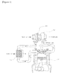
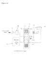
- the adiabatic compressed air energy storage for automotive vehicle comprises a power generator 10, a vehicle compressor 20, an additional compressor 30, a heat exchanger 40, a storage tank 50, a power generating section 60, and a heat storage section 70 (thermochemical storage section).
- the power generator 10 is connected to a turbo charger of an automotive vehicle via a power transfer means such as axis, etc. so as to generate first power A, and an electric generator may be used.
- the turbo charger For the power source to forcibly pressurize and increase the density of the air introduced into the cylinder of an engine 11, the turbo charger is operated by using high temperature combustion exhaust gas and generated axial power is connected to the vehicle compressor so that the compressed air is supplied to the engine 11 (intake side), and is located under an exhaust manifold.
- the exhaust gas which is emitted out of an automotive vehicle after explosion inside the engine cylinder, is also introduced into a turbine 12. With the pressure of the exhaust gas introduced into the turbine, a turbine wheel inside the turbine 12 is rotated.
- a compressor wheel inside the vehicle compressor 20 being located in opposite to the turbine wheel and being connected each other in power transferable is also rotated with the rotation of the turbine wheel. With the rotation of the compressor wheel, the air out of the compressor is taken in, and is cooled down via cooling section 13 such as intercooler, etc. and is forcibly supplied into the cylinder of the engine 11 (supercharging).
- the present invention provides a power generating system in which after decoupling the vehicle compressor 20 and the turbo charger mechanically and in power-transferable connected via axis for supercharging of the engine 11, the power generator 10 is connected to the vehicle compressor 20, the turbine axis of the turbo charger is rotated by the exhaust gas produced from the engine 11 and the power generator 10 is operated so as to generate a first power A.
- the vehicle compressor 20 is a compressor, which was connected to the turbine 12 via axis, in order to use the turbo charger.
- the function of the vehicle compressor 20 is to supercharge the engine 11 as described above.
- the vehicle compressor 20 is not directly connected to the turbine 12, and is configured as compressor to be driven by electric power, which is the first power A generated from the power generator 10.
- the vehicle compressor 20 is driven by the first power A and its function is to supercharge the engine 11. That is, the vehicle compressor 20 used for supercharging of the engine 11 is not driven by the rotation power of the turbine 12, but is driven by receiving the first power A from the power generator 10 being driven by the rotation power of the turbine 12, or the power from other generating means such as a third power C.
- the additional compressor 30 is provided inside a vehicle.
- the first power A of the power generator 10 which is used to drive the vehicle compressor 20 is also used to drive the additional compressor 30.
- a plurality of photovoltaic modules (PV module) 90 for generating solar energy are installed on the outer surface of a vehicle so as to generate a third power C. Even while a vehicle is not being driven, that is, when the engine 11 is stopped and exhaust gas is not supplied to the turbine 12, the additional compressor 30 can be driven by the third power C.
- the PV modules are electrically connected to the additional compressor 30.
- the additional compressor 30 is driven by the first power A or the third power C to intake and press outer air and produce compressed air of high temperature and high pressure.
- the heat exchanger 40 is provided to be connected to the additional compressor 30, and functions to cool down the compressed air, which is compressed via the additional compressor 30 and have high temperature and high pressure.
- the heat exchanger 40 turns the compressed air with high temperature and high pressure to the compressed air with low temperature and high pressure by heat-exchanging the high temperature and high pressure compressed air with outer air.
- the outer air which is increased in its temperature by the heat exchange with the high temperature and high pressure compressed air, is moved to the heat storage section 70 to be described later.
- the storage tank 50 stores the low temperature and high pressure compressed air, which has lower temperature by the heat exchange while passing the heat exchanger 40 than when discharged out of the additional compressor 30.
- the compressed air with high pressure stored in the storage tank 50 will be used to operate the power generating section 60, which will be described later, when power supply is demanded by a user or various power demands.
- the heat storage section 70 is connected to the aforementioned heat exchanger 40 and the later-described storage tank 50, and is composed of a plurality of heat storage units 71 having a storage material 72 in solid state to enable store heat energy therein and generate heat energy.
- the example of the storage material 72 may be MgSO 4 .7H 2 O (Magnesium Sulfate).
- the heat storage section 70 takes in the high temperature outer air which is increased in its temperature by the heat exchange with the high temperature and high pressure compressed air in the heat exchanger 40.
- the dehydration of the storage material is occurred to remove the water element from the storage material 72 and produces the storage material 72 having latent heat, which is enable to generate heat, and steam.
- the generated steam as result of the dehydration process from the heat storage section 70 (or the plurality of the heat storage units 71) is moved to a steam processing section 80 via a separate discharge pipe.
- a sensor is installed in each of the heat storage units 71 of the heat storage section 70 so that a user can monitor the heat storage state in the heat storage section 70 outside by using the sensors.
- the sensor may be a temperature sensor for detecting the temperature inside the heat storage units, or various kinds of sensors may be employed.
- each case of the heat storage units 71 is figured to see through inside so that a user can monitor outside weather the storage material 72 is separated into water and the heat storage material storing heat or not, and which state the storage material 72 is in among solid state, liquid state, and gas state.
- the low temperature high pressure compressed air stored in the storage tank 50 is supplied to the power generating section 60 to be described below when power for use is demanded in a vehicle. At this time, the compressed air stored in the storage tank 50 needs expanding for use. To facilitate the expansion of the compressed air, the heat for reaction is required at first, and the heat for reaction is supplied from the heat energy (exothermic energy) stored in the storage material 72 described as above.
- the heat is used for the expansion of the compressed air discharged from the storage tank 50.
- the low temperature high pressure compressed air discharged from the storage tank 50 is expanded by using the energy of the heat and supplied to the power generating section 60.
- the steam processing section 80 functions to receive the steam generated from the heat storage section 70 and store in the condensate water state, or change the stored condensate water into the steam state and supply the steam to the heat storage section 70.
- the steam processing section 80 comprises a condensation unit 81 to cool down the steam generated from the heat storage section 70 and change the steam into condensate water state, and a condensate water tank 82 to store the condensate water condensed in the condensation unit 81.
- a cooling fan may be used for the condensation unit 81.
- the steam processing section 80 comprises a heating unit 83 operated by using a separate electricity power source.
- the condensate water in the liquid state in the condensate water tank 82 is heated by using the heating unit 83 so as to be supplied again to the heat storage section 70 in the steam state, when the heat energy stored in the storage material 72 of the heat storage section 70 is requested to generate, that is, when it is necessary to expand the compressed air stored in the storage tank 50 to supply to the heat generating section 60.
- the condensate water stored in the condensate water tank 82 is heated by using the heating unit 83, and supplied as steam.
- the steam is set to be supplied until the heat generating of the storage material 72 in the heat storage units 71 reaches a predetermined level.
- the heating unit 83 for heating the condensate water in the condensate water tank 82 to generate steam is turned off.
- the power generating section 60 is where the high temperature high pressure air expanded by the heat energy generated the heat storage section 70 by using the steam supplied from the steam processing section 80 is introduced, and is operated by the introduced high temperature high pressure compressed air so as to generate a second power B for use in power demands.
- an air turbine or turbo expander may be used for the power generating section 60. If it is able to generate power by the operation using compressed air, various means may be used for the power generating section 60 besides the aforementioned air turbine or turbo expander.
Landscapes
- Engineering & Computer Science (AREA)
- Mechanical Engineering (AREA)
- Combustion & Propulsion (AREA)
- Chemical & Material Sciences (AREA)
- General Engineering & Computer Science (AREA)
- Physics & Mathematics (AREA)
- Life Sciences & Earth Sciences (AREA)
- Sustainable Development (AREA)
- Sustainable Energy (AREA)
- Thermal Sciences (AREA)
- Transportation (AREA)
- Electric Propulsion And Braking For Vehicles (AREA)
- Supercharger (AREA)
- Arrangement Or Mounting Of Propulsion Units For Vehicles (AREA)
Applications Claiming Priority (1)
| Application Number | Priority Date | Filing Date | Title |
|---|---|---|---|
| KR1020120092683A KR101300699B1 (ko) | 2012-08-24 | 2012-08-24 | 압축공기 에너지저장을 이용한 차량용 전력저장장치 및 이의 전력저장방법 |
Publications (2)
| Publication Number | Publication Date |
|---|---|
| EP2706201A2 true EP2706201A2 (de) | 2014-03-12 |
| EP2706201A3 EP2706201A3 (de) | 2018-03-21 |
Family
ID=49110986
Family Applications (1)
| Application Number | Title | Priority Date | Filing Date |
|---|---|---|---|
| EP13181510.2A Withdrawn EP2706201A3 (de) | 2012-08-24 | 2013-08-23 | Adiabatischer Druckluftenergiespeicher für Kraftfahrzeug und Energiespeicherungsverfahren damit |
Country Status (4)
| Country | Link |
|---|---|
| US (1) | US9234454B2 (de) |
| EP (1) | EP2706201A3 (de) |
| KR (1) | KR101300699B1 (de) |
| WO (1) | WO2014030794A1 (de) |
Families Citing this family (4)
| Publication number | Priority date | Publication date | Assignee | Title |
|---|---|---|---|---|
| WO2019113575A1 (en) | 2017-12-08 | 2019-06-13 | Schlumberger Technology Corporation | Compressed n2 for energy storage |
| CN114033515B (zh) * | 2021-11-09 | 2023-04-28 | 西安西热节能技术有限公司 | 具有引射汇流装置的液态压缩空气储能方法及系统 |
| EP4519543A4 (de) * | 2022-05-05 | 2025-12-31 | Cyclazoom Llc | Getrennte kompressoranordnungen für motoren |
| US11441425B1 (en) * | 2022-05-05 | 2022-09-13 | Cyclazoom, LLC | Separate compressor arrangements for engines |
Family Cites Families (32)
| Publication number | Priority date | Publication date | Assignee | Title |
|---|---|---|---|---|
| US3765180A (en) * | 1972-08-03 | 1973-10-16 | R Brown | Compressed air engine |
| US4089176A (en) * | 1976-01-20 | 1978-05-16 | The Garrett Corporation | Heat storage method and apparatus |
| US4361204A (en) * | 1980-02-11 | 1982-11-30 | Earle John L | Hot gas vehicular power system with regeneration |
| DE3326992C1 (de) * | 1983-07-27 | 1984-12-13 | Dr.Ing.H.C. F. Porsche Ag, 7000 Stuttgart | Antriebsaggregat,insbesondere fuer Kraftfahrzeuge |
| JP2510855B2 (ja) * | 1986-02-10 | 1996-06-26 | いすゞ自動車株式会社 | 車両におけるエネルギ−回収装置 |
| US5191766A (en) * | 1991-06-10 | 1993-03-09 | Vines Frank L | Hybrid internal combustion/steam engine |
| US5385214A (en) * | 1992-11-30 | 1995-01-31 | Spurgeon; John E. | Heat storage system utilized in heat engine drive system |
| US5385211A (en) * | 1993-05-12 | 1995-01-31 | Carroll; Robert D. | Electric power plant for vehicles |
| IT1272684B (it) * | 1993-09-27 | 1997-06-26 | Gianluigi Reis | Sistema di ricupero energia dissipata, durante la sua marcia, da un veicolo a motore a combustione interna |
| US5680764A (en) * | 1995-06-07 | 1997-10-28 | Clean Energy Systems, Inc. | Clean air engines transportation and other power applications |
| US6920759B2 (en) * | 1996-12-24 | 2005-07-26 | Hitachi, Ltd. | Cold heat reused air liquefaction/vaporization and storage gas turbine electric power system |
| DE69738474T2 (de) | 1997-09-22 | 2009-01-15 | Clean Energy Systems, Inc., Rancho Cordova | Reinluftmotoren für transport und andere motorisierte anwendungen |
| US6054838A (en) * | 1998-07-23 | 2000-04-25 | Tsatsis; Constantinos | Pressurized electric charging |
| US6450283B1 (en) * | 2000-11-27 | 2002-09-17 | Michael Blake Taggett | Waste heat conversion system |
| KR200262634Y1 (ko) | 2001-10-17 | 2002-03-18 | 이갑선 | 자동차용 엔진을 이용한 복합 보일러 시스템 |
| JP2003175721A (ja) | 2001-12-11 | 2003-06-24 | Hitachi Ltd | 蓄熱式車両空気調和装置 |
| US20040189008A1 (en) * | 2003-03-26 | 2004-09-30 | Constantinos Tsatsis | Magneto-turbine electric charging |
| US6955052B2 (en) * | 2003-12-11 | 2005-10-18 | Primlani Indru J | Thermal gas compression engine |
| US20070068712A1 (en) * | 2005-09-23 | 2007-03-29 | Carnahan Eric S | Hybrid Electric Vehicle |
| US7559394B2 (en) * | 2006-03-17 | 2009-07-14 | Gm Global Technology Operations, Inc. | Energy recovery system |
| DE102006057247A1 (de) | 2006-12-05 | 2008-06-12 | Robert Bosch Gmbh | Aufladeeinrichtung |
| GB0624599D0 (en) * | 2006-12-09 | 2007-01-17 | Aeristech Ltd | Engine induction system |
| US8261552B2 (en) * | 2007-01-25 | 2012-09-11 | Dresser Rand Company | Advanced adiabatic compressed air energy storage system |
| WO2008154455A2 (en) * | 2007-06-06 | 2008-12-18 | Ausra, Inc. | Granular thermal energy storage mediums and devices for thermal energy storage systems |
| US7926274B2 (en) * | 2007-06-08 | 2011-04-19 | FSTP Patent Holding Co., LLC | Rankine engine with efficient heat exchange system |
| US7921944B2 (en) * | 2007-10-29 | 2011-04-12 | Ford Global Technologies, Llc | Compression system for internal combustion engine including a rotationally uncoupled exhaust gas turbine |
| US20090205892A1 (en) * | 2008-02-19 | 2009-08-20 | Caterpillar Inc. | Hydraulic hybrid powertrain with exhaust-heated accumulator |
| BRPI1007723A2 (pt) * | 2009-05-12 | 2018-03-06 | Icr Turbine Engine Corp | sistema de armazenamento e conversão de turbina a gás |
| DE102009040311A1 (de) * | 2009-07-07 | 2011-02-03 | Lang, Dieter, Dipl.-Ing. (FH) | Vorrichtung zum Antreiben eines Kraftfahrzeugs |
| US20110094231A1 (en) * | 2009-10-28 | 2011-04-28 | Freund Sebastian W | Adiabatic compressed air energy storage system with multi-stage thermal energy storage |
| DE102010056238A1 (de) * | 2010-12-24 | 2012-06-28 | Audi Ag | Antrieb mit einer Brennkraftmaschine und einer Expansionsmaschine mit Gasrückführung |
| US8851043B1 (en) * | 2013-03-15 | 2014-10-07 | Lightsail Energy, Inc. | Energy recovery from compressed gas |
-
2012
- 2012-08-24 KR KR1020120092683A patent/KR101300699B1/ko not_active Expired - Fee Related
- 2012-09-14 WO PCT/KR2012/007369 patent/WO2014030794A1/ko not_active Ceased
-
2013
- 2013-08-09 US US13/963,370 patent/US9234454B2/en active Active
- 2013-08-23 EP EP13181510.2A patent/EP2706201A3/de not_active Withdrawn
Non-Patent Citations (1)
| Title |
|---|
| None * |
Also Published As
| Publication number | Publication date |
|---|---|
| US9234454B2 (en) | 2016-01-12 |
| EP2706201A3 (de) | 2018-03-21 |
| KR101300699B1 (ko) | 2013-08-26 |
| WO2014030794A1 (ko) | 2014-02-27 |
| US20140053552A1 (en) | 2014-02-27 |
Similar Documents
| Publication | Publication Date | Title |
|---|---|---|
| US8397504B2 (en) | Method and apparatus to recover and convert waste heat to mechanical energy | |
| US6516615B1 (en) | Hydrogen engine apparatus with energy recovery | |
| CN102182583A (zh) | 一种适用于内燃机的复合式余热回收系统 | |
| US20120031079A1 (en) | Hybrid powertrain system including an internal combustion engine and a stirling engine | |
| JP2008281002A (ja) | 内燃機関の運転方法、及び、内燃機関の吸気温度管理システム | |
| CN104220715A (zh) | 利用来自内燃机的废热驱动co2捕集系统的co2压缩机的方法 | |
| CN108374714A (zh) | 一种有机朗肯循环进气增压内燃机系统及方法 | |
| US9234454B2 (en) | Adiabatic compressed air energy storage for automotive vehicle and energy storage method using the same | |
| CN108979771A (zh) | 氢内燃机汽车高压储氢罐压力能回收装置 | |
| CN103775243A (zh) | 循环利用发动机冷却液的汽车余热发电技术 | |
| CN113202643B (zh) | 一种具有能量回收装置的系统及控制方法 | |
| CN102174906A (zh) | 一种汽车电涡流缓速器制动热能回收利用装置及控制方法 | |
| CN108643994B (zh) | 一种车载发动机排气能量多级联合回收装置 | |
| Treutler et al. | Combination of ORC system and electrified auxiliaries on a long haul truck equipped with 48-Volt board net | |
| WO2016038384A1 (en) | An internal combustion engine with a 4-stroke expansion cycle | |
| CN117489471A (zh) | 一种主辅机集成一体化动力装置及热电联供系统 | |
| WO2014108706A2 (en) | Cryogenic engine system | |
| CN108644021B (zh) | 一种车载发动机排气能量多级联合回收控制方法 | |
| Kadunic et al. | Cool2Power–increased petrol engine power and efficiency through an AC driven intercooling system | |
| CN102400746B (zh) | 基于蓄能器原理的汽车尾气余热利用系统 | |
| CN202325776U (zh) | 基于蓄能器原理的汽车尾气余热利用系统 | |
| CN202499008U (zh) | 一种混合动力汽车 | |
| CN111559239A (zh) | 气电混合汽车 | |
| De Lima et al. | Study on exergy recovery in hybrid vehicles via wastegate losses | |
| CN119142132B (zh) | 长续航商用车氢内燃机混合动力系统及车载储氢方式评估 |
Legal Events
| Date | Code | Title | Description |
|---|---|---|---|
| PUAI | Public reference made under article 153(3) epc to a published international application that has entered the european phase |
Free format text: ORIGINAL CODE: 0009012 |
|
| 17P | Request for examination filed |
Effective date: 20130823 |
|
| AK | Designated contracting states |
Kind code of ref document: A2 Designated state(s): AL AT BE BG CH CY CZ DE DK EE ES FI FR GB GR HR HU IE IS IT LI LT LU LV MC MK MT NL NO PL PT RO RS SE SI SK SM TR |
|
| AX | Request for extension of the european patent |
Extension state: BA ME |
|
| PUAL | Search report despatched |
Free format text: ORIGINAL CODE: 0009013 |
|
| AK | Designated contracting states |
Kind code of ref document: A3 Designated state(s): AL AT BE BG CH CY CZ DE DK EE ES FI FR GB GR HR HU IE IS IT LI LT LU LV MC MK MT NL NO PL PT RO RS SE SI SK SM TR |
|
| AX | Request for extension of the european patent |
Extension state: BA ME |
|
| RIC1 | Information provided on ipc code assigned before grant |
Ipc: F22B 1/02 20060101ALI20180213BHEP Ipc: F01K 3/10 20060101AFI20180213BHEP Ipc: F01K 15/02 20060101ALI20180213BHEP Ipc: F22B 1/18 20060101ALI20180213BHEP |
|
| GRAP | Despatch of communication of intention to grant a patent |
Free format text: ORIGINAL CODE: EPIDOSNIGR1 |
|
| STAA | Information on the status of an ep patent application or granted ep patent |
Free format text: STATUS: GRANT OF PATENT IS INTENDED |
|
| INTG | Intention to grant announced |
Effective date: 20200511 |
|
| STAA | Information on the status of an ep patent application or granted ep patent |
Free format text: STATUS: THE APPLICATION IS DEEMED TO BE WITHDRAWN |
|
| 18D | Application deemed to be withdrawn |
Effective date: 20200922 |