EP2705974A1 - Vehicle charging device - Google Patents
Vehicle charging device Download PDFInfo
- Publication number
- EP2705974A1 EP2705974A1 EP11874517.3A EP11874517A EP2705974A1 EP 2705974 A1 EP2705974 A1 EP 2705974A1 EP 11874517 A EP11874517 A EP 11874517A EP 2705974 A1 EP2705974 A1 EP 2705974A1
- Authority
- EP
- European Patent Office
- Prior art keywords
- power supply
- actuator
- side connector
- locked
- locking
- Prior art date
- Legal status (The legal status is an assumption and is not a legal conclusion. Google has not performed a legal analysis and makes no representation as to the accuracy of the status listed.)
- Withdrawn
Links
- 238000001514 detection method Methods 0.000 claims abstract description 30
- 230000004044 response Effects 0.000 claims abstract description 12
- 230000007246 mechanism Effects 0.000 description 25
- 230000000694 effects Effects 0.000 description 4
- 230000005281 excited state Effects 0.000 description 4
- 230000037431 insertion Effects 0.000 description 4
- 238000003780 insertion Methods 0.000 description 4
- 230000008439 repair process Effects 0.000 description 4
- 230000005856 abnormality Effects 0.000 description 2
- 230000013011 mating Effects 0.000 description 2
- 230000000149 penetrating effect Effects 0.000 description 2
- 229920003002 synthetic resin Polymers 0.000 description 2
- 239000000057 synthetic resin Substances 0.000 description 2
- 239000000470 constituent Substances 0.000 description 1
- 238000010586 diagram Methods 0.000 description 1
- 230000005611 electricity Effects 0.000 description 1
- 230000002093 peripheral effect Effects 0.000 description 1
- 230000003449 preventive effect Effects 0.000 description 1
- 230000007704 transition Effects 0.000 description 1
Images






Classifications
-
- B—PERFORMING OPERATIONS; TRANSPORTING
- B60—VEHICLES IN GENERAL
- B60L—PROPULSION OF ELECTRICALLY-PROPELLED VEHICLES; SUPPLYING ELECTRIC POWER FOR AUXILIARY EQUIPMENT OF ELECTRICALLY-PROPELLED VEHICLES; ELECTRODYNAMIC BRAKE SYSTEMS FOR VEHICLES IN GENERAL; MAGNETIC SUSPENSION OR LEVITATION FOR VEHICLES; MONITORING OPERATING VARIABLES OF ELECTRICALLY-PROPELLED VEHICLES; ELECTRIC SAFETY DEVICES FOR ELECTRICALLY-PROPELLED VEHICLES
- B60L53/00—Methods of charging batteries, specially adapted for electric vehicles; Charging stations or on-board charging equipment therefor; Exchange of energy storage elements in electric vehicles
- B60L53/10—Methods of charging batteries, specially adapted for electric vehicles; Charging stations or on-board charging equipment therefor; Exchange of energy storage elements in electric vehicles characterised by the energy transfer between the charging station and the vehicle
- B60L53/14—Conductive energy transfer
-
- B—PERFORMING OPERATIONS; TRANSPORTING
- B60—VEHICLES IN GENERAL
- B60L—PROPULSION OF ELECTRICALLY-PROPELLED VEHICLES; SUPPLYING ELECTRIC POWER FOR AUXILIARY EQUIPMENT OF ELECTRICALLY-PROPELLED VEHICLES; ELECTRODYNAMIC BRAKE SYSTEMS FOR VEHICLES IN GENERAL; MAGNETIC SUSPENSION OR LEVITATION FOR VEHICLES; MONITORING OPERATING VARIABLES OF ELECTRICALLY-PROPELLED VEHICLES; ELECTRIC SAFETY DEVICES FOR ELECTRICALLY-PROPELLED VEHICLES
- B60L3/00—Electric devices on electrically-propelled vehicles for safety purposes; Monitoring operating variables, e.g. speed, deceleration or energy consumption
- B60L3/0023—Detecting, eliminating, remedying or compensating for drive train abnormalities, e.g. failures within the drive train
- B60L3/0069—Detecting, eliminating, remedying or compensating for drive train abnormalities, e.g. failures within the drive train relating to the isolation, e.g. ground fault or leak current
-
- B—PERFORMING OPERATIONS; TRANSPORTING
- B60—VEHICLES IN GENERAL
- B60L—PROPULSION OF ELECTRICALLY-PROPELLED VEHICLES; SUPPLYING ELECTRIC POWER FOR AUXILIARY EQUIPMENT OF ELECTRICALLY-PROPELLED VEHICLES; ELECTRODYNAMIC BRAKE SYSTEMS FOR VEHICLES IN GENERAL; MAGNETIC SUSPENSION OR LEVITATION FOR VEHICLES; MONITORING OPERATING VARIABLES OF ELECTRICALLY-PROPELLED VEHICLES; ELECTRIC SAFETY DEVICES FOR ELECTRICALLY-PROPELLED VEHICLES
- B60L3/00—Electric devices on electrically-propelled vehicles for safety purposes; Monitoring operating variables, e.g. speed, deceleration or energy consumption
- B60L3/04—Cutting off the power supply under fault conditions
-
- B—PERFORMING OPERATIONS; TRANSPORTING
- B60—VEHICLES IN GENERAL
- B60L—PROPULSION OF ELECTRICALLY-PROPELLED VEHICLES; SUPPLYING ELECTRIC POWER FOR AUXILIARY EQUIPMENT OF ELECTRICALLY-PROPELLED VEHICLES; ELECTRODYNAMIC BRAKE SYSTEMS FOR VEHICLES IN GENERAL; MAGNETIC SUSPENSION OR LEVITATION FOR VEHICLES; MONITORING OPERATING VARIABLES OF ELECTRICALLY-PROPELLED VEHICLES; ELECTRIC SAFETY DEVICES FOR ELECTRICALLY-PROPELLED VEHICLES
- B60L53/00—Methods of charging batteries, specially adapted for electric vehicles; Charging stations or on-board charging equipment therefor; Exchange of energy storage elements in electric vehicles
- B60L53/10—Methods of charging batteries, specially adapted for electric vehicles; Charging stations or on-board charging equipment therefor; Exchange of energy storage elements in electric vehicles characterised by the energy transfer between the charging station and the vehicle
- B60L53/14—Conductive energy transfer
- B60L53/16—Connectors, e.g. plugs or sockets, specially adapted for charging electric vehicles
-
- B—PERFORMING OPERATIONS; TRANSPORTING
- B60—VEHICLES IN GENERAL
- B60L—PROPULSION OF ELECTRICALLY-PROPELLED VEHICLES; SUPPLYING ELECTRIC POWER FOR AUXILIARY EQUIPMENT OF ELECTRICALLY-PROPELLED VEHICLES; ELECTRODYNAMIC BRAKE SYSTEMS FOR VEHICLES IN GENERAL; MAGNETIC SUSPENSION OR LEVITATION FOR VEHICLES; MONITORING OPERATING VARIABLES OF ELECTRICALLY-PROPELLED VEHICLES; ELECTRIC SAFETY DEVICES FOR ELECTRICALLY-PROPELLED VEHICLES
- B60L53/00—Methods of charging batteries, specially adapted for electric vehicles; Charging stations or on-board charging equipment therefor; Exchange of energy storage elements in electric vehicles
- B60L53/30—Constructional details of charging stations
- B60L53/305—Communication interfaces
-
- H—ELECTRICITY
- H01—ELECTRIC ELEMENTS
- H01R—ELECTRICALLY-CONDUCTIVE CONNECTIONS; STRUCTURAL ASSOCIATIONS OF A PLURALITY OF MUTUALLY-INSULATED ELECTRICAL CONNECTING ELEMENTS; COUPLING DEVICES; CURRENT COLLECTORS
- H01R13/00—Details of coupling devices of the kinds covered by groups H01R12/70 or H01R24/00 - H01R33/00
- H01R13/62—Means for facilitating engagement or disengagement of coupling parts or for holding them in engagement
- H01R13/639—Additional means for holding or locking coupling parts together, after engagement, e.g. separate keylock, retainer strap
-
- H—ELECTRICITY
- H01—ELECTRIC ELEMENTS
- H01R—ELECTRICALLY-CONDUCTIVE CONNECTIONS; STRUCTURAL ASSOCIATIONS OF A PLURALITY OF MUTUALLY-INSULATED ELECTRICAL CONNECTING ELEMENTS; COUPLING DEVICES; CURRENT COLLECTORS
- H01R13/00—Details of coupling devices of the kinds covered by groups H01R12/70 or H01R24/00 - H01R33/00
- H01R13/66—Structural association with built-in electrical component
- H01R13/70—Structural association with built-in electrical component with built-in switch
- H01R13/701—Structural association with built-in electrical component with built-in switch the switch being actuated by an accessory, e.g. cover, locking member
-
- B—PERFORMING OPERATIONS; TRANSPORTING
- B60—VEHICLES IN GENERAL
- B60L—PROPULSION OF ELECTRICALLY-PROPELLED VEHICLES; SUPPLYING ELECTRIC POWER FOR AUXILIARY EQUIPMENT OF ELECTRICALLY-PROPELLED VEHICLES; ELECTRODYNAMIC BRAKE SYSTEMS FOR VEHICLES IN GENERAL; MAGNETIC SUSPENSION OR LEVITATION FOR VEHICLES; MONITORING OPERATING VARIABLES OF ELECTRICALLY-PROPELLED VEHICLES; ELECTRIC SAFETY DEVICES FOR ELECTRICALLY-PROPELLED VEHICLES
- B60L2250/00—Driver interactions
- B60L2250/10—Driver interactions by alarm
-
- B—PERFORMING OPERATIONS; TRANSPORTING
- B60—VEHICLES IN GENERAL
- B60L—PROPULSION OF ELECTRICALLY-PROPELLED VEHICLES; SUPPLYING ELECTRIC POWER FOR AUXILIARY EQUIPMENT OF ELECTRICALLY-PROPELLED VEHICLES; ELECTRODYNAMIC BRAKE SYSTEMS FOR VEHICLES IN GENERAL; MAGNETIC SUSPENSION OR LEVITATION FOR VEHICLES; MONITORING OPERATING VARIABLES OF ELECTRICALLY-PROPELLED VEHICLES; ELECTRIC SAFETY DEVICES FOR ELECTRICALLY-PROPELLED VEHICLES
- B60L2270/00—Problem solutions or means not otherwise provided for
- B60L2270/30—Preventing theft during charging
- B60L2270/32—Preventing theft during charging of electricity
-
- B—PERFORMING OPERATIONS; TRANSPORTING
- B60—VEHICLES IN GENERAL
- B60L—PROPULSION OF ELECTRICALLY-PROPELLED VEHICLES; SUPPLYING ELECTRIC POWER FOR AUXILIARY EQUIPMENT OF ELECTRICALLY-PROPELLED VEHICLES; ELECTRODYNAMIC BRAKE SYSTEMS FOR VEHICLES IN GENERAL; MAGNETIC SUSPENSION OR LEVITATION FOR VEHICLES; MONITORING OPERATING VARIABLES OF ELECTRICALLY-PROPELLED VEHICLES; ELECTRIC SAFETY DEVICES FOR ELECTRICALLY-PROPELLED VEHICLES
- B60L2270/00—Problem solutions or means not otherwise provided for
- B60L2270/30—Preventing theft during charging
- B60L2270/34—Preventing theft during charging of parts
-
- Y—GENERAL TAGGING OF NEW TECHNOLOGICAL DEVELOPMENTS; GENERAL TAGGING OF CROSS-SECTIONAL TECHNOLOGIES SPANNING OVER SEVERAL SECTIONS OF THE IPC; TECHNICAL SUBJECTS COVERED BY FORMER USPC CROSS-REFERENCE ART COLLECTIONS [XRACs] AND DIGESTS
- Y02—TECHNOLOGIES OR APPLICATIONS FOR MITIGATION OR ADAPTATION AGAINST CLIMATE CHANGE
- Y02T—CLIMATE CHANGE MITIGATION TECHNOLOGIES RELATED TO TRANSPORTATION
- Y02T10/00—Road transport of goods or passengers
- Y02T10/60—Other road transportation technologies with climate change mitigation effect
- Y02T10/70—Energy storage systems for electromobility, e.g. batteries
-
- Y—GENERAL TAGGING OF NEW TECHNOLOGICAL DEVELOPMENTS; GENERAL TAGGING OF CROSS-SECTIONAL TECHNOLOGIES SPANNING OVER SEVERAL SECTIONS OF THE IPC; TECHNICAL SUBJECTS COVERED BY FORMER USPC CROSS-REFERENCE ART COLLECTIONS [XRACs] AND DIGESTS
- Y02—TECHNOLOGIES OR APPLICATIONS FOR MITIGATION OR ADAPTATION AGAINST CLIMATE CHANGE
- Y02T—CLIMATE CHANGE MITIGATION TECHNOLOGIES RELATED TO TRANSPORTATION
- Y02T10/00—Road transport of goods or passengers
- Y02T10/60—Other road transportation technologies with climate change mitigation effect
- Y02T10/7072—Electromobility specific charging systems or methods for batteries, ultracapacitors, supercapacitors or double-layer capacitors
-
- Y—GENERAL TAGGING OF NEW TECHNOLOGICAL DEVELOPMENTS; GENERAL TAGGING OF CROSS-SECTIONAL TECHNOLOGIES SPANNING OVER SEVERAL SECTIONS OF THE IPC; TECHNICAL SUBJECTS COVERED BY FORMER USPC CROSS-REFERENCE ART COLLECTIONS [XRACs] AND DIGESTS
- Y02—TECHNOLOGIES OR APPLICATIONS FOR MITIGATION OR ADAPTATION AGAINST CLIMATE CHANGE
- Y02T—CLIMATE CHANGE MITIGATION TECHNOLOGIES RELATED TO TRANSPORTATION
- Y02T90/00—Enabling technologies or technologies with a potential or indirect contribution to GHG emissions mitigation
- Y02T90/10—Technologies relating to charging of electric vehicles
- Y02T90/12—Electric charging stations
-
- Y—GENERAL TAGGING OF NEW TECHNOLOGICAL DEVELOPMENTS; GENERAL TAGGING OF CROSS-SECTIONAL TECHNOLOGIES SPANNING OVER SEVERAL SECTIONS OF THE IPC; TECHNICAL SUBJECTS COVERED BY FORMER USPC CROSS-REFERENCE ART COLLECTIONS [XRACs] AND DIGESTS
- Y02—TECHNOLOGIES OR APPLICATIONS FOR MITIGATION OR ADAPTATION AGAINST CLIMATE CHANGE
- Y02T—CLIMATE CHANGE MITIGATION TECHNOLOGIES RELATED TO TRANSPORTATION
- Y02T90/00—Enabling technologies or technologies with a potential or indirect contribution to GHG emissions mitigation
- Y02T90/10—Technologies relating to charging of electric vehicles
- Y02T90/14—Plug-in electric vehicles
-
- Y—GENERAL TAGGING OF NEW TECHNOLOGICAL DEVELOPMENTS; GENERAL TAGGING OF CROSS-SECTIONAL TECHNOLOGIES SPANNING OVER SEVERAL SECTIONS OF THE IPC; TECHNICAL SUBJECTS COVERED BY FORMER USPC CROSS-REFERENCE ART COLLECTIONS [XRACs] AND DIGESTS
- Y02—TECHNOLOGIES OR APPLICATIONS FOR MITIGATION OR ADAPTATION AGAINST CLIMATE CHANGE
- Y02T—CLIMATE CHANGE MITIGATION TECHNOLOGIES RELATED TO TRANSPORTATION
- Y02T90/00—Enabling technologies or technologies with a potential or indirect contribution to GHG emissions mitigation
- Y02T90/10—Technologies relating to charging of electric vehicles
- Y02T90/16—Information or communication technologies improving the operation of electric vehicles
Definitions
- the present invention relates to a vehicle charging device with an improved lock mechanism.
- a power supply side connector connected to a power supply is connected to a vehicle side connector provided in the vehicle and connected to the battery such as at home or at a gas station, whereby the battery is charged with power supplied from a commercial power supply. Since this charging requires a relatively long time, the both connectors are often left in a connected state. During that time, the power supply side connector may inadvertently come off such as because a power supply cord is tripped over or the power supply side connector may be unduly pulled out for the purpose of stealing electricity. Thus, measures for preventing these need to be taken.
- a charging device provided with an electromagnetic lock mechanism is proposed as an example of the preventive measure.
- This includes a locked portion provided in a housing of a power supply side connector, whereas a solenoid-type actuator is provided in a vehicle side connector.
- a locking portion advances and is locked to the locked portion to effect locking as the actuator is exited, and then a power supply path is set to an electrically conductive state and charging is performed.
- the power supply path is cut off.
- the locking portion may not return to a proper retreated position for some cause when the actuator is brought to the non-exciting state and the locking portion retreats to release locking. At this time, locking is still effected and there is a high possibility of a half-locked state. Thus, if the power supply side connector is detached with such a situation unnoticed, an excessive load acts on the locking portion, the locked portion and the like to damage them.
- the present invention was completed based on the above situation and aims to be able to warn when there is an abnormality in a retreating movement of a locking portion of an actuator constituting an electromagnetic lock mechanism.
- the present invention is directed to a vehicle charging device with a power supply side connector connected to an external power supply, a vehicle side connector connected to a battery mounted in a vehicle and provided in the vehicle to form a power supply path by being connected to the power supply side connector, a power supply switch for switchingly connecting and cutting off the power supply path, and a solenoid-type actuator provided in the vehicle side connector and including a locking portion to be locked to a locked portion of the power supply side connector and capable of being driven to advance and retreat, the both connectors being locked in a connected state by an advancing movement of the locking portion of the actuator to be locked to the locked portion and then the power supply switch being switched to connect the power supply path when the both connectors are connected, and the power supply switch being switched to cut off the power supply path and then locking being released by retreating the locking portion of the actuator when charging ends, including a movement detector for detecting whether or not the locking portion of the actuator is at a retreated position; an error discriminator for discriminating the occurrence of an error and sending an error signal when the
- the locking portion does not return to the proper retreated position for some cause and this is detected by the movement detector when the locking portion of the actuator is driven to retreat to release locking, the occurrence of an error is assumed and an error signal is output.
- a warning is given, i.e. it is notified that locking is not completely released. If it is attempted to forcibly detach the vehicle side connector in such a state, an electromagnetic lock mechanism may be damaged.
- a user or the like is caused to wait for the detaching operation of the vehicle side connector, whereby the damage of the electromagnetic lock mechanism is prevented and, in addition, the repair or the like of the actuator can be quickly dealt with.
- a housing of the power supply side connector includes a receptacle into which a housing of the vehicle side connector is fittable and a locked hole is formed on the receptacle, thereby forming the locked portion; and the actuator including a locking pin movable back and forth through the locked hole is provided in the housing of the vehicle side connector and the locking portion is formed by the locking pin.
- the movement detector is formed by a microswitch whose open and closed states are reversed by being pressed by a pressing portion provided on a base end side of the locking pin of the actuator.
- the pressing portion presses the microswitch to switch the open/closed state, whereby the return is detected. Conversely, it is assumed that the locking pin has not returned to the proper rear end position if the microswitch is not pressed and the open/closed state is not switched.
- FIGS. 1 to 11 One embodiment of the present invention is described based on FIGS. 1 to 11 .
- a vehicle charging device of this embodiment includes a power supply side connector 10 connected to a power supply and a vehicle side connector 20 connected to a battery mounted in a vehicle and provided in the vehicle.
- the power supply side connector 10 is so structured that a female housing 12 is provided on a tip part of a connector main body 11 with a grip part 11A, both the connector main body 11 and the female housing 12 being made of synthetic resin.
- the female housing 12 is so structured that seven terminal accommodating tubes 14 independent of each other and projecting from the back wall are provided in a small receptacle 13 (corresponding to a receptacle of the present invention). Two, three and two terminal accommodating tubes 14 are respectively arranged in an upper row, a middle row and a lower row in correspondence with the arrangement of seven cavities 25 provided in a mating male housing 21 to be described later.
- female power terminals for AC are accommodated in the terminal accommodating tubes 14A on the opposite sides of the middle row
- a female ground terminal 15 is accommodated in the middle terminal accommodating tube 14A of the middle row
- female signal terminals are accommodated in the both terminal accommodating tubes 14B of the upper row.
- the both terminal accommodating tubes 14C in the lower row are for accommodating female power terminals for DC, they are empty in this connector 10.
- Wires connected to the respective female connection terminals are bundled in the connector main body 11 and drawn out from the rear end of the grip part 11A in the connector main body 11 in the form of a multi-core cable 16.
- the vehicle side connector 20 includes the male housing 21 likewise made of synthetic resin.
- the male housing 21 includes a terminal accommodating portion 22 whose front end side is fittable into the small receptacle 13 of the above female housing 12, and a large receptacle 24 formed to be fittable onto the outer periphery of the small receptacle 13 to surround the front end side of the terminal accommodating portion 22.
- seven cavities 25 into which the respective terminal accommodating tubes 14 of the above female housing 12 are fittable from front are formed in a corresponding arrangement in the terminal accommodating portion 22 of the male housing 21.
- a male connection terminal is so accommodated in each cavity 25 as to project from the back wall.
- male power terminals 26A for AC are accommodated in the cavities 25A on the opposite sides of a middle row
- a male ground terminal 26B is accommodated in the middle cavity 25A of the middle row
- male signal terminals 26C are accommodated in the both cavities 25B in an upper row.
- Male power terminals for DC may be accommodated in the both cavities 25C in a lower row or these cavities may be empty.
- a rectangular mounting plate 28 is formed in a projecting manner at a position of the outer peripheral surface of the large receptacle 24 of the male housing 21 near the tip and four corners of this mounting plate 28 are fixed to a mounting member arranged in a power supply port open on the body of the vehicle by screws, whereby the male housing 21 is mounted in such a manner that a connection surface thereof is facing the power supply port.
- the terminal accommodating portion 22 of the male housing 21 is inserted into the small receptacle 13 of the female housing 12
- the small receptacle 13 of the female housing 12 is inserted into a receptacle entrance groove 29 formed between the terminal accommodating portion 22 and the large receptacle 24 in the male housing 21
- the front surface of the terminal accommodating portion 22 comes into contact with a back wall 13A of the small receptacle 13
- the tip edge of the small receptacle 13 comes into contact with a back wall 29A of the receptacle entrance groove 29 as shown in FIG 4 , whereby a connecting operation is stopped and this position becomes a proper connection position.
- the both connectors 10, 20 When the both connectors 10, 20 are properly connected, the corresponding male and female connection terminals provided in the both connectors 10, 20 are connected to each other.
- the power terminals including the ground terminals 15, 27 When the power terminals including the ground terminals 15, 27 are connected, a power supply path is formed between the power supply and the battery mounted in the vehicle.
- a power supply switch 30 (see FIG. 8 ) for switching the state of the power supply path between an electrically conductive state and a cut-off state is provided in this power supply path.
- connection detection terminals serve as connection detection terminals and a connected part of the connection detection terminals serve as a connection detector 31.
- An electromagnetic lock mechanism 40 is provided which locks the housings 12, 21 of the both connectors 10, 20 in a properly connected state.
- a locked hole 17 is formed at a position of the upper surface of the small receptacle 13 near the tip in the female housing 12 provided in the power supply side connector 10.
- a solenoid-type actuator 41 is provided in the vehicle side connector 20.
- This actuator 41 is so provided that a locking pin 43 is movable between a retreated position ( FIG 2 ) and an advanced position ( FIG 4 ) relative to a main body 42 and the locking pin 43 is constantly biased toward the retreated position by a spring force.
- the actuator 41 is energized and excited, the locking pin 43 moves to the advanced position against a biasing force.
- the locked hole 17 of the small receptacle 13 of the female housing 12 is also formed on the lower, left and right surfaces so as to deal with cases where the actuator 41 is arranged at a lower position and left and right positions besides the upper position described above.
- a guide hole 46 into which the locking pin 43 of the actuator 41 is tightly insertable is formed at a position of the upper surface of the large receptacle 24 near the rear end in the male housing 21 of the vehicle side connector 20, specifically at a position right above the locked hole 17 of the small receptacle 13 when the female and male housings 12, 21 are properly connected.
- an escaping recess 47 for allowing a tip part of the locking pin 43 to escape is formed on the upper surface of the terminal accommodating portion 22, i.e. at a position of the lower surface of the receptacle insertion groove 29 right below the guide hole 46.
- the guide hole 46 and the escaping recess 47 are also provided on the lower, left and right surfaces in correspondence with the arrangement position of the above actuator 41.
- the actuator 41 is mounted onto the vehicle side connector 20 in a posture facing right below with the tip of the locking pin 43 inserted in the guide hole 46.
- a basic charging control system including a locking operation by the electromagnetic lock mechanism 40 is described below with reference to FIGS. 8 and 9 .
- the actuator 41 When the proper connection of the both connectors 10, 20 is detected through the connection of a pair of signal terminals constituting the connection detector 31, the actuator 41 is excited, whereby the locking pin 43 at the retreated position moves to the advanced position, the tip of the locking pin 43 reaches the escaping recess 47 through the locked hole 17 of the small receptacle 13 and the locking pin 43 is locked to a front edge part (locked portion 18) of the locked hole 17.
- the both connectors 10, 20 are locked in the properly connected state and, subsequently, the power supply switch 30 is turned on to set the power supply path to the electrically conductive state and charging is performed.
- a charging end detector 32 FIG 8
- the power supply switch 30 When the end of predetermined charging is detected by a charging end detector 32 ( FIG 8 ) provided in the vehicle side connector 20, the power supply switch 30 is turned off to cut off the power supply path. Subsequently, when a lock release command is issued from a lock release commander 33 ( FIG 8 ), power application to the actuator 41 is cut off to set the actuator 41 to a non-exciting state, whereby the locking pin 43 returns to the retreated position to release locking and a state is entered where the power supply side connector 10 is detachable. Note that a release command signal from the lock release commander 33 may be sent upon the detection of the charging end or by operating an operation unit separately provided on the vehicle side.
- measures are taken such as to indicate an operation failure and restrict a power supplying operation in the case of this operation failure, considering that the electromagnetic lock mechanism 40 does not properly operate in some cases. These measures are described below.
- various detectors are provided which detect the presence or absence of a failure in each constituent component of the electromagnetic lock mechanism 40, signals and the like from such detectors are computed by a power supply controller 71 ( FIG 8 ) and various members are controlled based on the computation result.
- a first detection switch 51 (locking portion detector) is provided as a means for detecting a failure in the locking pin 43 of the actuator 41.
- This first detection switch 51 is a normally open switch including a pair of movable contacts 51 A and a fixed contact 51B, and arranged such that the movable contacts 51 A are faced up in the escaping recess 47 provided on the bottom surface of the receptacle insertion groove 29 in the above male housing 21.
- the tip of the locking pin 43 cannot press the movable contacts 51A despite the advancing movement of the locking pin 43 and the first detection switch 51 is kept off.
- a second detection switch 52 (locked portion detector) is provided as a means for detecting a failure that the locked portion 18 constituting one side of the electromagnetic lock mechanism 40 is missing.
- This second detection switch 52 is similarly a normally open switch including a pair of movable contacts 52A and a fixed contact 52B.
- the second detection switch 52 is arranged at the following position. As also shown in FIG 3 , a guide path 54 extending along forward and backward directions is formed in an area behind the back wall 29A of the receptacle insertion groove 29 on the upper surface of the terminal accommodating portion 22 of the male housing 21, more specifically in an area behind the arrangement position of the first detection switch 51, and the second detection switch 52 is mounted in a rear end part of this guide path 54 with the movable contacts 52A arranged on a front side.
- An operating plate 55 is placed in the guide path 54 slidably in forward and backward directions, and a pushed piece 55A projecting from the front surface of the operating plate 55 projects into the receptacle insertion groove 29 through a guide hole 54A formed on the back wall 29A.
- the locked portion 18 pushes the pushed piece 55A to retreat the operating plate 55 by a predetermined amount and the rear edge of the operating plate 55 pushes the movable contacts 52A and brings them into contact with the fixed contact 52B to turn on the second detection switch 52 if the locked portion 18 is properly present.
- a movement detector is provided which detects advancing and retreating movements of the locking pin 43 of the actuator 41.
- a microswitch 60 is arranged laterally of a movement path for the locking pin 43 of the actuator 41, whereas a flange 44 engageable with an operation lever 61 of the microswitch 60 is formed on the outer periphery of a base end part of the locking pin 43.
- the microswitch 60 is, for example, a normally open switch.
- the flange 44 pushes a button 62 via the operation lever 61 to turn on the microswitch 60 as shown in FIG. 2 .
- the locking pin 43 advances by a predetermined amount or more as shown in FIG 4 , the flange 44 is separated and a force pressing the operation lever 61 is released to return the button 62, whereby the microswitch 60 is turned off.
- the microswitch 60 as the movement detector, the first detection switch 51 as the locking portion detector and the second detection switch 52 as the locked portion detector described above are connected to an input side of a charging control device 70 as shown in FIG 8 .
- a power supply controller 71 including a lock error discriminator 72 is built in the charging control device 70 to deal with cases where the electromagnetic lock mechanism 40 does not properly operate, specifically both a case where there is a failure in the locking pin 43 of the actuator 41 and a case where the locked portion 18 is missing.
- the power supply controller 71 a program as shown in FIG 10 is executed.
- the actuator 41 is excited and, thereafter, the power supply path is set to the electrically conductive state only after the both detectors are turned on.
- An error signal is output if one of the both detectors is off and an indication is made by an indicator 75 in response to this error signal.
- This indicator 75 includes an indicator lamp formed of a light-emitting diode and is, as shown in FIG 1 , provided at an upper position of the mounting plate 28 on the male housing 21 of the vehicle side connector 20 so as to be visible through the power supply port.
- an actuator error discriminator 73 is built in the charging control device 70 to deal with a case where the locking pin 43 of the actuator 41 does not properly return to the retreated position in releasing locking.
- the lock release commander 33 is connected to the input side of the charging control device 70 as partly already described.
- the lock release commander 33 is interlocked with the charging end detector 32 and outputs a lock release command signal upon detecting the end of the charging.
- the lock release commander 33 may output a lock release command signal upon the operation of a lock release operation unit separately provided on the vehicle side.
- the actuator error discriminator 73 a program as shown in FIG 11 is executed. Specifically, when the end of the charging is detected, the power supply path is cut off. Thereafter, when a lock release command is received, the excited state of the actuator is released. At that time, if the return of the locking pin 43 to the retreated position is not detected, an error signal is output and an indication is made by the indicator 75 in response to this error signal. Note that an indicator lamp different from the above indicator lamp may be turned on in the indicator 75.
- Step S10 when the power supply side connector 10 is properly connected to the vehicle side connector 20 as shown in FIG. 4 , a pair of signal terminals are connected to turn on the connection detector 31 ("YES” in Step S10), whereby the actuator 41 is energized and excited (Step S11). This causes the locking pin 43 to advance to penetrate through the locked hole 17 of the male housing 21. Subsequently, in Step S12, whether or not the first detection switch 51 is on is discriminated. If the first detection switch 51 is on (“YES" in Step S12), the tip of the locking pin 43 moves to the proper advanced position, i.e. the locking pin 43 is assumed to have properly penetrated through the locked hole 17, and a transition is made to Step S13.
- Step S13 whether or not the second detection switch 52 is on is discriminated. If the second detection switch 52 is on ("YES" in Step S13), the locked portion 18, which is the front edge of the locked hole 17 of the male housing 21, is present and locked to the locking pin 43, i.e. the electromagnetic lock mechanism 40 is assumed to have properly operated to effect locking. In Step S14, the power supply switch 30 is switched to the electrically conductive state to start charging.
- Step S 15 a lock error is assumed and an error signal is sent.
- the indicator lamp of the indicator 75 is turned on to notify a failure in the electromagnetic lock mechanism 40.
- the power supply switch 30 is kept off and charging is not performed.
- Step S12 the first detection switch 51 is kept off since the tip of the locking pin 43 does not press the movable contacts 51 A even if the locking pin 43 advances.
- Step S 15 a lock error is assumed and an error signal is sent to turn on the indicator lamp of the indicator 75. Similarly, charging is not performed.
- Step S15 a lock error is assumed and an error signal is sent to turn on the indicator lamp of the indicator 75 in response to this error signal, thereby notifying a failure in the electromagnetic lock mechanism 40.
- the power supply switch 30 is kept off and charging is not performed.
- locking may be incomplete and the vehicle side connector 20 may be inadvertently or unduly detached in any of the cases of the half-locked state, the lacking tip part of the actuator 41 and the missing locked portion 18.
- the electromagnetic lock mechanism 40 it is detected and charging is restricted and, on the other hand, the presence of this failure is indicated by the indicator 75 to call attention to the repair or the like of the failure.
- Step S20 In normal time, if the end of the charging is detected ("YES” in Step S20), the power supply switch 30 is turned off in Step S21 to cut off the power supply path. Thereafter, when a lock release command is output (“YES” in Step S22), power application to the actuator 41 is cut off to release the excited state and the locking pin 43 retreats as shown by an arrow B of FIG 5 in Step S23.
- a lock release command is output (“YES” in Step S22)
- the actuator 41 is cut off to release the excited state and the locking pin 43 retreats as shown by an arrow B of FIG 5 in Step S23.
- Step S24 After the excited state of the actuator 41 is released, the locking pin 43 enters a state where it cannot be returned to the proper retreated position for some reason such as a trouble. If this is detected by that the microswitch 60 is not turned on ("NO" in Step S24), an actuator error is assumed and an error signal is sent in Step S25. In response to this error signal, the indicator lamp of the indicator 75 is turned on to notify that the locking pin 43 of the actuator 41 has not returned to the proper retreated position, i.e. locking is not completely released.
- the electromagnetic lock mechanism 40 may be damaged.
- a user or the like is caused to wait for the detaching operation of the vehicle side connector 20 and, in addition, attention is called to the repair or the like of the actuator 41.
- the following effects can be obtained. If the locking pin 43 does not properly return to the retreated position when the actuator 41 is set to the non-exciting state and the locking pin 43 is retreated to release locking, there is a possibility that the locking pin 43 is still penetrating through the locked hole 17 of the mating power supply side connector 10 or the tip of the locking pin 43 stays in the locked hole 17. If it is attempted to detach the power supply side connector 10 in this state, an excessive load may be applied to the locking pin 43 and the locked portion 18 to damage them or damage the actuator 41 itself.
- the user or the like refrains from detaching the power supply side connector 10, whereby the damage of the electromagnetic lock mechanism 40 is prevented and the repair or the like of the actuator 41 can be quickly dealt with.
Landscapes
- Engineering & Computer Science (AREA)
- Power Engineering (AREA)
- Transportation (AREA)
- Mechanical Engineering (AREA)
- Life Sciences & Earth Sciences (AREA)
- Sustainable Development (AREA)
- Sustainable Energy (AREA)
- Details Of Connecting Devices For Male And Female Coupling (AREA)
- Electric Propulsion And Braking For Vehicles (AREA)
- Charge And Discharge Circuits For Batteries Or The Like (AREA)
Abstract
A vehicle charging device configured such that a power supply switch 30 is switched to cut off a power supply path and then a locking portion 43 of an actuator 41 is retreated to release locking when charging ends includes a movement detector 60 for detecting whether or not the locking portion 43 of the actuator 41 is at a retreated position, an error discriminator 73 for discriminating the occurrence of an error and sending an error signal when the return of the locking portion 43 to the retreated position is not detected by the movement detection 60 although the locking portion 43 of the actuator 41 is driven to retreat, and a warning unit 75 for giving a warning in response to the error signal.
Description
- The present invention relates to a vehicle charging device with an improved lock mechanism.
- In the case of charging a vehicle equipped with a battery such as an electric vehicle or a plug-in hybrid vehicle, a power supply side connector connected to a power supply is connected to a vehicle side connector provided in the vehicle and connected to the battery such as at home or at a gas station, whereby the battery is charged with power supplied from a commercial power supply. Since this charging requires a relatively long time, the both connectors are often left in a connected state. During that time, the power supply side connector may inadvertently come off such as because a power supply cord is tripped over or the power supply side connector may be unduly pulled out for the purpose of stealing electricity. Thus, measures for preventing these need to be taken.
- Conventionally, a charging device provided with an electromagnetic lock mechanism is proposed as an example of the preventive measure. This includes a locked portion provided in a housing of a power supply side connector, whereas a solenoid-type actuator is provided in a vehicle side connector. When the power supply side connector is connected to the vehicle side connector and the proper connection of the both connectors is detected, a locking portion advances and is locked to the locked portion to effect locking as the actuator is exited, and then a power supply path is set to an electrically conductive state and charging is performed. When predetermined charging is completed after the passage of time, the power supply path is cut off. Subsequently, as the actuator is brought into a non-exciting state, the locking portion retreats and is disengaged from the locked portion, whereby locking is released and the power supply side connector can be detached. Note that this type of a charging device provided with an electromagnetic lock mechanism is disclosed in patent literature 1 below.
-
- Patent Literature 1: Japanese Unexamined Patent Publication No.
2011-81952 - In the above conventional electromagnetic lock mechanism, the locking portion may not return to a proper retreated position for some cause when the actuator is brought to the non-exciting state and the locking portion retreats to release locking. At this time, locking is still effected and there is a high possibility of a half-locked state. Thus, if the power supply side connector is detached with such a situation unnoticed, an excessive load acts on the locking portion, the locked portion and the like to damage them.
- The present invention was completed based on the above situation and aims to be able to warn when there is an abnormality in a retreating movement of a locking portion of an actuator constituting an electromagnetic lock mechanism.
- The present invention is directed to a vehicle charging device with a power supply side connector connected to an external power supply, a vehicle side connector connected to a battery mounted in a vehicle and provided in the vehicle to form a power supply path by being connected to the power supply side connector, a power supply switch for switchingly connecting and cutting off the power supply path, and a solenoid-type actuator provided in the vehicle side connector and including a locking portion to be locked to a locked portion of the power supply side connector and capable of being driven to advance and retreat, the both connectors being locked in a connected state by an advancing movement of the locking portion of the actuator to be locked to the locked portion and then the power supply switch being switched to connect the power supply path when the both connectors are connected, and the power supply switch being switched to cut off the power supply path and then locking being released by retreating the locking portion of the actuator when charging ends, including a movement detector for detecting whether or not the locking portion of the actuator is at a retreated position; an error discriminator for discriminating the occurrence of an error and sending an error signal when the return of the locking portion to the retreated position is not detected by the movement detection although the locking portion of the actuator is driven to retreat; and a warning unit for giving a warning in response to the error signal.
- If the locking portion does not return to the proper retreated position for some cause and this is detected by the movement detector when the locking portion of the actuator is driven to retreat to release locking, the occurrence of an error is assumed and an error signal is output. In response to this error signal, a warning is given, i.e. it is notified that locking is not completely released. If it is attempted to forcibly detach the vehicle side connector in such a state, an electromagnetic lock mechanism may be damaged. Thus, a user or the like is caused to wait for the detaching operation of the vehicle side connector, whereby the damage of the electromagnetic lock mechanism is prevented and, in addition, the repair or the like of the actuator can be quickly dealt with.
- Further, the following configurations may be adopted.
- (1) A housing of the power supply side connector includes a receptacle into which a housing of the vehicle side connector is fittable and a locked hole is formed on the receptacle, thereby forming the locked portion; and the actuator including a locking pin movable back and forth through the locked hole is provided in the housing of the vehicle side connector and the locking portion is formed by the locking pin.
- If the locking pin of the actuator does not properly return to the retreated position, there is a possibility that the locking pin is still penetrating through the locked hole or the tip of the locking portion stays in the locked hole. If it is attempted to detach the power supply side connector in this state, an excessive load may be applied to the locking pin and the locked portion to damage them or damage the actuator itself. However, the above damage is prevented by avoiding the detachment of the power supply side connector upon receiving a warning.
- (2) The movement detector is formed by a microswitch whose open and closed states are reversed by being pressed by a pressing portion provided on a base end side of the locking pin of the actuator.
- If the locking pin of the actuator is driven to retreat and properly returns to the retreated position, the pressing portion presses the microswitch to switch the open/closed state, whereby the return is detected. Conversely, it is assumed that the locking pin has not returned to the proper rear end position if the microswitch is not pressed and the open/closed state is not switched.
- According to the present invention, it is possible to detect and warn when there is an abnormality in a retreating movement of a locking portion of an actuator constituting an electromagnetic lock mechanism.
-
-
FIG 1 is a perspective view showing a state before a power supply side connector and a vehicle side connector according to one embodiment of the present invention are connected, -
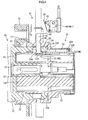
FIG 2 is a longitudinal section showing the state ofFIG 1 , -
FIG 3 is a perspective section of the vehicle side connector, -
FIG 4 is a longitudinal section showing a state where the power supply side connector and the vehicle side connector are properly connected, -
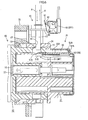
FIG 5 is a longitudinal section when there is a failure in an advancing or retreating movement of a locking pin of an actuator, -
FIG 6 is a longitudinal section when the locking pin of the actuator is damaged, -
FIG 7 is a longitudinal section when a locked portion is damaged, -
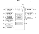
FIG. 8 is a block diagram showing a charging control mechanism, -
FIG 9 is a flow chart outlining a charging control system, -
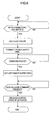
FIG 10 is a flow chart of a power supply control mode, and -
FIG 11 is a flow chart showing a mode for detecting a return failure of the locking pin of the actuator. - One embodiment of the present invention is described based on
FIGS. 1 to 11 . - As shown in
FIGS. 1 and2 , a vehicle charging device of this embodiment includes a powersupply side connector 10 connected to a power supply and avehicle side connector 20 connected to a battery mounted in a vehicle and provided in the vehicle. - The power
supply side connector 10 is so structured that afemale housing 12 is provided on a tip part of a connectormain body 11 with agrip part 11A, both the connectormain body 11 and thefemale housing 12 being made of synthetic resin. Thefemale housing 12 is so structured that seven terminalaccommodating tubes 14 independent of each other and projecting from the back wall are provided in a small receptacle 13 (corresponding to a receptacle of the present invention). Two, three and two terminalaccommodating tubes 14 are respectively arranged in an upper row, a middle row and a lower row in correspondence with the arrangement of sevencavities 25 provided in a matingmale housing 21 to be described later. - Out of the above
terminal accommodating tubes 14, female power terminals for AC are accommodated in theterminal accommodating tubes 14A on the opposite sides of the middle row, afemale ground terminal 15 is accommodated in the middleterminal accommodating tube 14A of the middle row, and female signal terminals are accommodated in the bothterminal accommodating tubes 14B of the upper row. Note that although the bothterminal accommodating tubes 14C in the lower row are for accommodating female power terminals for DC, they are empty in thisconnector 10. Wires connected to the respective female connection terminals are bundled in the connectormain body 11 and drawn out from the rear end of thegrip part 11A in the connectormain body 11 in the form of amulti-core cable 16. - The
vehicle side connector 20 includes themale housing 21 likewise made of synthetic resin. Themale housing 21 includes a terminal accommodatingportion 22 whose front end side is fittable into thesmall receptacle 13 of the abovefemale housing 12, and alarge receptacle 24 formed to be fittable onto the outer periphery of thesmall receptacle 13 to surround the front end side of theterminal accommodating portion 22. As partly already described, sevencavities 25 into which the respectiveterminal accommodating tubes 14 of the abovefemale housing 12 are fittable from front are formed in a corresponding arrangement in theterminal accommodating portion 22 of themale housing 21. - A male connection terminal is so accommodated in each
cavity 25 as to project from the back wall. Specifically,male power terminals 26A for AC are accommodated in thecavities 25A on the opposite sides of a middle row, amale ground terminal 26B is accommodated in themiddle cavity 25A of the middle row, and male signal terminals 26C are accommodated in the bothcavities 25B in an upper row. Male power terminals for DC may be accommodated in the both cavities 25C in a lower row or these cavities may be empty. - A
rectangular mounting plate 28 is formed in a projecting manner at a position of the outer peripheral surface of thelarge receptacle 24 of themale housing 21 near the tip and four corners of thismounting plate 28 are fixed to a mounting member arranged in a power supply port open on the body of the vehicle by screws, whereby themale housing 21 is mounted in such a manner that a connection surface thereof is facing the power supply port. - When the
female housing 12 of the powersupply side connector 10 is connected to themale housing 21 of thevehicle side connector 20, theterminal accommodating portion 22 of themale housing 21 is inserted into thesmall receptacle 13 of thefemale housing 12, thesmall receptacle 13 of thefemale housing 12 is inserted into areceptacle entrance groove 29 formed between the terminalaccommodating portion 22 and thelarge receptacle 24 in themale housing 21, the front surface of theterminal accommodating portion 22 comes into contact with aback wall 13A of thesmall receptacle 13 and the tip edge of thesmall receptacle 13 comes into contact with aback wall 29A of thereceptacle entrance groove 29 as shown inFIG 4 , whereby a connecting operation is stopped and this position becomes a proper connection position. - When the both
connectors connectors ground terminals FIG. 8 ) for switching the state of the power supply path between an electrically conductive state and a cut-off state is provided in this power supply path. - On the other hand, when two pairs of male and female signal terminals are connected to each other, two signal lines are formed. In this embodiment, one out of these is used for connection detection of the both
connectors FIG 3 ) serve as connection detection terminals and a connected part of the connection detection terminals serve as aconnection detector 31. - An
electromagnetic lock mechanism 40 is provided which locks thehousings connectors - As shown in
FIG 2 , a lockedhole 17 is formed at a position of the upper surface of thesmall receptacle 13 near the tip in thefemale housing 12 provided in the powersupply side connector 10. - On the other hand, a solenoid-
type actuator 41 is provided in thevehicle side connector 20. Thisactuator 41 is so provided that a lockingpin 43 is movable between a retreated position (FIG 2 ) and an advanced position (FIG 4 ) relative to amain body 42 and the lockingpin 43 is constantly biased toward the retreated position by a spring force. When theactuator 41 is energized and excited, the lockingpin 43 moves to the advanced position against a biasing force. - Note that the locked
hole 17 of thesmall receptacle 13 of thefemale housing 12 is also formed on the lower, left and right surfaces so as to deal with cases where theactuator 41 is arranged at a lower position and left and right positions besides the upper position described above. - A
guide hole 46 into which thelocking pin 43 of theactuator 41 is tightly insertable is formed at a position of the upper surface of thelarge receptacle 24 near the rear end in themale housing 21 of thevehicle side connector 20, specifically at a position right above the lockedhole 17 of thesmall receptacle 13 when the female andmale housings recess 47 for allowing a tip part of the lockingpin 43 to escape is formed on the upper surface of theterminal accommodating portion 22, i.e. at a position of the lower surface of thereceptacle insertion groove 29 right below theguide hole 46. Note that theguide hole 46 and the escapingrecess 47 are also provided on the lower, left and right surfaces in correspondence with the arrangement position of theabove actuator 41. - The
actuator 41 is mounted onto thevehicle side connector 20 in a posture facing right below with the tip of the lockingpin 43 inserted in theguide hole 46. - A basic charging control system including a locking operation by the
electromagnetic lock mechanism 40 is described below with reference toFIGS. 8 and9 . - When the proper connection of the both
connectors connection detector 31, theactuator 41 is excited, whereby the lockingpin 43 at the retreated position moves to the advanced position, the tip of the lockingpin 43 reaches the escapingrecess 47 through the lockedhole 17 of thesmall receptacle 13 and the lockingpin 43 is locked to a front edge part (locked portion 18) of the lockedhole 17. In this way, the bothconnectors power supply switch 30 is turned on to set the power supply path to the electrically conductive state and charging is performed. - When the end of predetermined charging is detected by a charging end detector 32 (
FIG 8 ) provided in thevehicle side connector 20, thepower supply switch 30 is turned off to cut off the power supply path. Subsequently, when a lock release command is issued from a lock release commander 33 (FIG 8 ), power application to theactuator 41 is cut off to set theactuator 41 to a non-exciting state, whereby the lockingpin 43 returns to the retreated position to release locking and a state is entered where the powersupply side connector 10 is detachable. Note that a release command signal from thelock release commander 33 may be sent upon the detection of the charging end or by operating an operation unit separately provided on the vehicle side. - In this embodiment, measures are taken such as to indicate an operation failure and restrict a power supplying operation in the case of this operation failure, considering that the
electromagnetic lock mechanism 40 does not properly operate in some cases. These measures are described below. - Basically, various detectors are provided which detect the presence or absence of a failure in each constituent component of the
electromagnetic lock mechanism 40, signals and the like from such detectors are computed by a power supply controller 71 (FIG 8 ) and various members are controlled based on the computation result. - First, as shown in
FIG 2 , a first detection switch 51 (locking portion detector) is provided as a means for detecting a failure in the lockingpin 43 of theactuator 41. Thisfirst detection switch 51 is a normally open switch including a pair ofmovable contacts 51 A and afixed contact 51B, and arranged such that themovable contacts 51 A are faced up in the escapingrecess 47 provided on the bottom surface of thereceptacle insertion groove 29 in the abovemale housing 21. - When the
actuator 41 is excited and the lockingpin 43 moves to the proper advanced position, the tip of the lockingpin 43 presses themovable contacts 51A and brings them into contact with the fixedcontact 51 B, whereby thefirst detection switch 51 is turned on. - On the other hand, for example, if the locking
pin 43 cannot move to the proper position for some reason or if the tip part of the lockingpin 43 is lacking, the tip of the lockingpin 43 cannot press themovable contacts 51A despite the advancing movement of the lockingpin 43 and thefirst detection switch 51 is kept off. - Further, a second detection switch 52 (locked portion detector) is provided as a means for detecting a failure that the locked
portion 18 constituting one side of theelectromagnetic lock mechanism 40 is missing. Thissecond detection switch 52 is similarly a normally open switch including a pair ofmovable contacts 52A and afixed contact 52B. - The
second detection switch 52 is arranged at the following position. As also shown inFIG 3 , aguide path 54 extending along forward and backward directions is formed in an area behind theback wall 29A of thereceptacle insertion groove 29 on the upper surface of theterminal accommodating portion 22 of themale housing 21, more specifically in an area behind the arrangement position of thefirst detection switch 51, and thesecond detection switch 52 is mounted in a rear end part of thisguide path 54 with themovable contacts 52A arranged on a front side. - An operating
plate 55 is placed in theguide path 54 slidably in forward and backward directions, and a pushedpiece 55A projecting from the front surface of the operatingplate 55 projects into thereceptacle insertion groove 29 through aguide hole 54A formed on theback wall 29A. - When the
female housing 12 of the powersupply side connector 10 is properly connected to themale housing 21 of thevehicle side connector 20, the lockedportion 18 pushes the pushedpiece 55A to retreat theoperating plate 55 by a predetermined amount and the rear edge of the operatingplate 55 pushes themovable contacts 52A and brings them into contact with the fixedcontact 52B to turn on thesecond detection switch 52 if the lockedportion 18 is properly present. - On the other hand, if the locked
portion 18 is damaged and missing, the pushedpiece 55A, i.e. the operatingplate 55 cannot be pushed backward, i.e. themovable contacts 52A cannot be pushed and thesecond detection switch 52 is kept off even if the bothconnectors - Further, a movement detector is provided which detects advancing and retreating movements of the locking
pin 43 of theactuator 41. - Specifically, a
microswitch 60 is arranged laterally of a movement path for the lockingpin 43 of theactuator 41, whereas aflange 44 engageable with anoperation lever 61 of themicroswitch 60 is formed on the outer periphery of a base end part of the lockingpin 43. - The
microswitch 60 is, for example, a normally open switch. When the lockingpin 43 is at the retreated position, theflange 44 pushes abutton 62 via theoperation lever 61 to turn on themicroswitch 60 as shown inFIG. 2 . On the other hand, when the lockingpin 43 advances by a predetermined amount or more as shown inFIG 4 , theflange 44 is separated and a force pressing theoperation lever 61 is released to return thebutton 62, whereby themicroswitch 60 is turned off. - The
microswitch 60 as the movement detector, thefirst detection switch 51 as the locking portion detector and thesecond detection switch 52 as the locked portion detector described above are connected to an input side of a chargingcontrol device 70 as shown inFIG 8 . - A
power supply controller 71 including alock error discriminator 72 is built in the chargingcontrol device 70 to deal with cases where theelectromagnetic lock mechanism 40 does not properly operate, specifically both a case where there is a failure in the lockingpin 43 of theactuator 41 and a case where the lockedportion 18 is missing. - In the
power supply controller 71, a program as shown inFIG 10 is executed. In short, when the proper connection of the bothconnectors actuator 41 is excited and, thereafter, the power supply path is set to the electrically conductive state only after the both detectors are turned on. An error signal is output if one of the both detectors is off and an indication is made by anindicator 75 in response to this error signal. - This
indicator 75 includes an indicator lamp formed of a light-emitting diode and is, as shown inFIG 1 , provided at an upper position of the mountingplate 28 on themale housing 21 of thevehicle side connector 20 so as to be visible through the power supply port. - Further, in this embodiment, an
actuator error discriminator 73 is built in the chargingcontrol device 70 to deal with a case where the lockingpin 43 of theactuator 41 does not properly return to the retreated position in releasing locking. Thus, thelock release commander 33 is connected to the input side of the chargingcontrol device 70 as partly already described. Thelock release commander 33 is interlocked with the chargingend detector 32 and outputs a lock release command signal upon detecting the end of the charging. Note that thelock release commander 33 may output a lock release command signal upon the operation of a lock release operation unit separately provided on the vehicle side. - In the
actuator error discriminator 73, a program as shown inFIG 11 is executed. Specifically, when the end of the charging is detected, the power supply path is cut off. Thereafter, when a lock release command is received, the excited state of the actuator is released. At that time, if the return of the lockingpin 43 to the retreated position is not detected, an error signal is output and an indication is made by theindicator 75 in response to this error signal. Note that an indicator lamp different from the above indicator lamp may be turned on in theindicator 75. - Next, functions of this embodiment are described.
- First, with reference to a flow chart of
FIG 10 , when the powersupply side connector 10 is properly connected to thevehicle side connector 20 as shown inFIG. 4 , a pair of signal terminals are connected to turn on the connection detector 31 ("YES" in Step S10), whereby theactuator 41 is energized and excited (Step S11). This causes the lockingpin 43 to advance to penetrate through the lockedhole 17 of themale housing 21. Subsequently, in Step S12, whether or not thefirst detection switch 51 is on is discriminated. If thefirst detection switch 51 is on ("YES" in Step S12), the tip of the lockingpin 43 moves to the proper advanced position, i.e. the lockingpin 43 is assumed to have properly penetrated through the lockedhole 17, and a transition is made to Step S13. In Step S13, whether or not thesecond detection switch 52 is on is discriminated. If thesecond detection switch 52 is on ("YES" in Step S13), the lockedportion 18, which is the front edge of the lockedhole 17 of themale housing 21, is present and locked to the lockingpin 43, i.e. theelectromagnetic lock mechanism 40 is assumed to have properly operated to effect locking. In Step S14, thepower supply switch 30 is switched to the electrically conductive state to start charging. - Here, if there is an operation failure in the
electromagnetic lock mechanism 40, e.g. if the lockingpin 43 has not reached the proper advanced position for some reason despite the advancing movement of the lockingpin 43 of theactuator 41 as shown by an arrow A ofFIG 5 , i.e. if a half-locked state is set, thefirst detection switch 51 is kept off ("NO" in Step S12) since the lockingpin 43 does not press themovable contacts 51A of thefirst detection switch 51. InStep S 15, a lock error is assumed and an error signal is sent. In response to this error signal, the indicator lamp of theindicator 75 is turned on to notify a failure in theelectromagnetic lock mechanism 40. On the other hand, thepower supply switch 30 is kept off and charging is not performed. - Further, as shown in
FIG. 6 , also when the tip part of the lockingpin 43 of theactuator 41 is lacking, thefirst detection switch 51 is kept off ("NO" in Step S12) since the tip of the lockingpin 43 does not press themovable contacts 51 A even if the lockingpin 43 advances. Likewise inStep S 15, a lock error is assumed and an error signal is sent to turn on the indicator lamp of theindicator 75. Similarly, charging is not performed. - As another case, when the locked
portion 18 constituting one side of theelectromagnetic lock mechanism 40 is damaged and missing as shown inFIG. 7 , thesecond detection switch 52 is kept off ("NO" in Step S13) since themovable contacts 52A of thesecond detection switch 52 are not pushed even if the lockingpin 43 advances to the proper position and thefirst detection switch 51 is turned on ("YES" in Step S12). Thus, in Step S15, a lock error is assumed and an error signal is sent to turn on the indicator lamp of theindicator 75 in response to this error signal, thereby notifying a failure in theelectromagnetic lock mechanism 40. On the other hand, thepower supply switch 30 is kept off and charging is not performed. - As described above, locking may be incomplete and the
vehicle side connector 20 may be inadvertently or unduly detached in any of the cases of the half-locked state, the lacking tip part of theactuator 41 and the missing lockedportion 18. However, if there is such a failure in theelectromagnetic lock mechanism 40, it is detected and charging is restricted and, on the other hand, the presence of this failure is indicated by theindicator 75 to call attention to the repair or the like of the failure. - On the other hand, if the
electromagnetic lock mechanism 40 properly operates as described above, charging is subsequently performed. Locking is released in response to a lock release command such as when predetermined charging is completed after the passage of time. At that time, the lockingpin 43 of theactuator 41 may not possibly properly return to the retreated position, i.e. locking may not possibly be properly released. A control mode at that time is described with reference to a flow chart ofFIG 11 . - In normal time, if the end of the charging is detected ("YES" in Step S20), the
power supply switch 30 is turned off in Step S21 to cut off the power supply path. Thereafter, when a lock release command is output ("YES" in Step S22), power application to theactuator 41 is cut off to release the excited state and the lockingpin 43 retreats as shown by an arrow B ofFIG 5 in Step S23. When the return of the lockingpin 43 to the proper retreated position as shown inFIG 2 is detected by that themicroswitch 60 is turned on ("YES" in Step S24), the program ends. - Here, after the excited state of the
actuator 41 is released, the lockingpin 43 enters a state where it cannot be returned to the proper retreated position for some reason such as a trouble. If this is detected by that themicroswitch 60 is not turned on ("NO" in Step S24), an actuator error is assumed and an error signal is sent in Step S25. In response to this error signal, the indicator lamp of theindicator 75 is turned on to notify that the lockingpin 43 of theactuator 41 has not returned to the proper retreated position, i.e. locking is not completely released. - If it is attempted to forcibly detach the
vehicle side connector 20 in such a state, theelectromagnetic lock mechanism 40 may be damaged. Thus, a user or the like is caused to wait for the detaching operation of thevehicle side connector 20 and, in addition, attention is called to the repair or the like of theactuator 41. - According to this embodiment, the following effects can be obtained. If the locking
pin 43 does not properly return to the retreated position when theactuator 41 is set to the non-exciting state and the lockingpin 43 is retreated to release locking, there is a possibility that the lockingpin 43 is still penetrating through the lockedhole 17 of the mating powersupply side connector 10 or the tip of the lockingpin 43 stays in the lockedhole 17. If it is attempted to detach the powersupply side connector 10 in this state, an excessive load may be applied to the lockingpin 43 and the lockedportion 18 to damage them or damage theactuator 41 itself. - In this embodiment, when it is detected by the
microswitch 60 that the lockingpin 43 has not properly returned to the retreated position after the excited state of theactuator 41 is released, an error in the returning movement of the lockingpin 43 is assumed and an error signal is sent. In response to this error signal, the indicator lamp of theindicator 75 is turned on, thereby notifying that the lockingpin 43 of theactuator 41 has not properly returned to the retreated position and locking is not completely released. - In response to that, the user or the like refrains from detaching the power
supply side connector 10, whereby the damage of theelectromagnetic lock mechanism 40 is prevented and the repair or the like of theactuator 41 can be quickly dealt with. - The present invention is not limited to the above described and illustrated embodiment. For example, the following embodiments are also included in the technical scope of the present invention.
- (1) Although the disk-shaped flange is illustrated as a pressing portion provided on the locking pin of the actuator engageably with the microswitch in the above embodiment, there is no limitation to that and the shape of the pressing portion may be another shape such as that of a pressing plate or the like projecting toward the microswitch.
- (2) The shape of the locking portion of the actuator is not limited to a pin shape such as that of the locking pin illustrated in the above embodiment and may be another shape such as a plate shape or a piece shape as long as the locking portion can be driven to advance and retreat. Further, the locked portion provided in the power supply side connector may have another shape such as that of a projection as long as it can be locked to the locking portion of the actuator.
- (3) The movement detector for detecting whether or not the locking portion of the actuator is at the retreated position is not limited to the microswitch illustrated in the above embodiment and a switch of another type such as a limit switch may be applied.
- (4) Although a lighting indication means for turning on a lamp is adopted as a means for warning a lock error in the actuator in the above embodiment, a warning tone generation means for sounding a buzzer instead of that may be used or both means may be used in combination.
- (5) The charging control system illustrated in the above embodiment is only an example and can be changed as appropriate. For example, the charging end detector may detect the end of the charging such as when a charging time set in advance elapses or when a charging end switch is manually operated besides when the battery is fully charged.
- (6) Although the illustrated vehicle side connector is compatible with both ordinary charging and quick charging in the above embodiment, the present invention can be similarly applied also when a vehicle side connector compatible with only either one of ordinary charging and quick charging is provided.
-
- 10
- power supply side connector
- 12
- female housing (housing of power supply side connector)
- 13
- small receptacle (receptacle)
- 17
- locked hole
- 18
- locked portion
- 20
- vehicle side connector
- 21
- male housing (housing of vehicle side connector)
- 30
- power supply switch
- 31
- connection detector
- 40
- electromagnetic lock mechanism
- 41
- actuator
- 43
- locking pin (locking portion)
- 44
- flange (pressing portion)
- 60
- microswitch (movement detector)
- 70
- charging control device
- 71
- power supply controller
- 73
- actuator error discriminator (error discriminator)
- 75
- indicator (warning unit)
Claims (3)
- A vehicle charging device with a power supply side connector connected to an external power supply, a vehicle side connector connected to a battery mounted in a vehicle and provided in the vehicle to form a power supply path by being connected to the power supply side connector, a power supply switch for switchingly connecting and cutting off the power supply path, and a solenoid-type actuator provided in the vehicle side connector and including a locking portion to be locked to a locked portion of the power supply side connector and capable of being driven to advance and retreat, the both connectors being locked in a connected state by an advancing movement of the locking portion of the actuator to be locked to the locked portion and then the power supply switch being switched to connect the power supply path when the both connectors are connected, and the power supply switch being switched to cut off the power supply path and then locking being released by retreating the locking portion of the actuator when charging ends, comprising:a movement detector for detecting whether or not the locking portion of the actuator is at a retreated position;an error discriminator for discriminating the occurrence of an error and sending an error signal when the return of the locking portion to the retreated position is not detected by the movement detection although the locking portion of the actuator is driven to retreat; anda warning unit for giving a warning in response to the error signal.
- The vehicle charging device of claim 1, wherein:a housing of the power supply side connector includes a receptacle into which a housing of the vehicle side connector is fittable and a locked hole is formed on the receptacle, thereby forming the locked portion; andthe actuator including a locking pin movable back and forth through the locked hole is provided in the housing of the vehicle side connector and the locking portion is formed by the locking pin.
- The vehicle charging device of claim 2, wherein:the movement detector is formed by a microswitch whose open and closed states are reversed by being pressed by a pressing portion provided on a base end side of the locking pin of the actuator.
Applications Claiming Priority (1)
| Application Number | Priority Date | Filing Date | Title |
|---|---|---|---|
| PCT/JP2011/074486 WO2013061400A1 (en) | 2011-10-25 | 2011-10-25 | Vehicle charging device |
Publications (1)
| Publication Number | Publication Date |
|---|---|
| EP2705974A1 true EP2705974A1 (en) | 2014-03-12 |
Family
ID=48167267
Family Applications (1)
| Application Number | Title | Priority Date | Filing Date |
|---|---|---|---|
| EP11874517.3A Withdrawn EP2705974A1 (en) | 2011-10-25 | 2011-10-25 | Vehicle charging device |
Country Status (5)
| Country | Link |
|---|---|
| US (1) | US20140292276A1 (en) |
| EP (1) | EP2705974A1 (en) |
| JP (1) | JP5610086B2 (en) |
| CN (1) | CN103687748A (en) |
| WO (1) | WO2013061400A1 (en) |
Cited By (4)
| Publication number | Priority date | Publication date | Assignee | Title |
|---|---|---|---|---|
| FR3030135A1 (en) * | 2014-12-11 | 2016-06-17 | Schneider Electric Ind Sas | SYSTEM FOR CONNECTING AN ELECTRIC POWER CIRCUIT AND CHARGING INSTALLATION OF AN ELECTRIC VEHICLE COMPRISING SUCH A CONNECTION SYSTEM |
| CN107776428A (en) * | 2017-10-24 | 2018-03-09 | 王若云 | A kind of new-energy automobile charging equipment |
| WO2018192624A1 (en) * | 2017-04-21 | 2018-10-25 | Harting Electric Gmbh & Co. Kg | Attachment housing arrangement and method for unlocking |
| GB2626525A (en) * | 2022-12-16 | 2024-07-31 | Myenergi Ltd | Electric vehicle supply apparatus |
Families Citing this family (32)
| Publication number | Priority date | Publication date | Assignee | Title |
|---|---|---|---|---|
| JP5798935B2 (en) * | 2012-01-17 | 2015-10-21 | 矢崎総業株式会社 | Electrical connector |
| JP5939927B2 (en) * | 2012-08-06 | 2016-06-22 | 矢崎総業株式会社 | Charging connector |
| JP5981294B2 (en) * | 2012-10-12 | 2016-08-31 | 矢崎総業株式会社 | Charging inlet device |
| JP5861609B2 (en) * | 2012-10-25 | 2016-02-16 | 株式会社オートネットワーク技術研究所 | Unlock control device |
| JP6009528B2 (en) * | 2014-12-18 | 2016-10-19 | 住友電装株式会社 | Charging inlet |
| FR3048560B1 (en) * | 2016-03-02 | 2019-07-05 | Aldebaran Robotics | BATTERY RECHARGING ASSEMBLY AND RECHARGING METHOD USING SUCH ASSEMBLY |
| EP3252879B1 (en) * | 2016-05-31 | 2020-08-26 | TE Connectivity Germany GmbH | Actuator module for charge inlets |
| JP2018037210A (en) * | 2016-08-30 | 2018-03-08 | 株式会社豊田自動織機 | Battery pack and charging port unit |
| CN106945561B (en) * | 2017-04-20 | 2018-07-31 | 江苏锡沂高新区科技发展有限公司 | A kind of new-energy automobile charging unit that can be automatically controlled |
| KR102322857B1 (en) * | 2017-04-28 | 2021-11-08 | 현대자동차주식회사 | Method for determining failure in charging connector locking system |
| CN106992371A (en) * | 2017-05-28 | 2017-07-28 | 詹胜超 | A kind of mobile phone part |
| DE102017211541B4 (en) * | 2017-07-06 | 2019-08-08 | Volkswagen Aktiengesellschaft | Locking system for a charging socket of a vehicle, charging socket with locking system, motor vehicle with charging socket and method for operating a motor vehicle |
| US10868389B2 (en) | 2017-08-21 | 2020-12-15 | Hubbell Incorporated | Electrical contact device with interlock |
| CN107394520B (en) * | 2017-09-05 | 2023-05-05 | 东台正耀精密技术有限公司 | electrical connector combination |
| CN108790899B (en) * | 2018-06-24 | 2020-08-21 | 湖南京能新能源科技有限公司 | Self-locking method of charging pile of direct-current electrified new energy automobile |
| US11341279B2 (en) | 2019-07-29 | 2022-05-24 | International Business Machines Corporation | Management of securable computing resources |
| US11341278B2 (en) | 2019-07-29 | 2022-05-24 | International Business Machines Corporation | Management of securable computing resources |
| US11669602B2 (en) | 2019-07-29 | 2023-06-06 | International Business Machines Corporation | Management of securable computing resources |
| US11531787B2 (en) | 2019-07-29 | 2022-12-20 | International Business Machines Corporation | Management of securable computing resources |
| US11210427B2 (en) | 2019-07-29 | 2021-12-28 | International Business Machines Corporation | Management of securable computing resources |
| US10916889B1 (en) * | 2019-07-29 | 2021-02-09 | International Business Machines Corporation | Management of securable computing resources |
| DE102019127197A1 (en) * | 2019-10-09 | 2021-04-15 | Sma Solar Technology Ag | METHOD OF LOCKING A PLUG ARRANGED ON A CHARGING CABLE WITH A MISCELLANEOUS PLUG AND CHARGING STATION FOR PERFORMING THE METHOD |
| US11370315B2 (en) * | 2020-08-25 | 2022-06-28 | Ford Global Technologies, Llc | Hands-free charging system with internal power source |
| CN114843133A (en) * | 2021-02-01 | 2022-08-02 | 东洋建苍电机股份有限公司 | motorcycle light switch |
| CN113895256B (en) * | 2021-10-09 | 2024-12-13 | 深圳市中蓝绿源科技有限公司 | A smart charging gun head |
| DE102022208502B4 (en) * | 2022-08-16 | 2024-04-04 | Franz Binder GmbH & Co Elektrische Bauelemente Kommanditgesellschaft | Electrical connector and connector system |
| USD1051826S1 (en) * | 2022-12-20 | 2024-11-19 | Shenzhen Kule Youpin Technology Co., Ltd | Charging adapter |
| USD1051827S1 (en) * | 2022-12-20 | 2024-11-19 | Shenzhen Kule Youpin Technology Co., Ltd. | Charging adapter |
| USD1061447S1 (en) * | 2023-03-16 | 2025-02-11 | Winchester Interconnect | Connector |
| USD1068684S1 (en) * | 2023-03-16 | 2025-04-01 | Winchester Interconnect | Connector |
| US20250178463A1 (en) * | 2023-12-04 | 2025-06-05 | Volley Automation, Inc. | Vehicle charging systems and methods for using same |
| CN117984825B (en) * | 2024-04-03 | 2024-09-06 | 福建省加成信息技术有限公司 | Mobile charging device and charging method thereof |
Family Cites Families (12)
| Publication number | Priority date | Publication date | Assignee | Title |
|---|---|---|---|---|
| JPH04312775A (en) * | 1991-04-10 | 1992-11-04 | Nec Corp | Connector |
| JP2752032B2 (en) * | 1993-09-20 | 1998-05-18 | 矢崎総業株式会社 | Power supply connector |
| JPH07272794A (en) * | 1994-03-31 | 1995-10-20 | Mitsubishi Electric Corp | Connector device |
| JP3058241B2 (en) * | 1994-09-08 | 2000-07-04 | 矢崎総業株式会社 | Ground connection method and ground connection structure of power supply connector |
| JPH08130062A (en) * | 1994-10-27 | 1996-05-21 | Sumitomo Wiring Syst Ltd | Connector provided with engagement detection function |
| JP5339983B2 (en) * | 2008-05-19 | 2013-11-13 | 富士重工業株式会社 | Electric vehicle control device |
| JP5297967B2 (en) | 2009-10-05 | 2013-09-25 | トヨタ自動車株式会社 | Connector locking mechanism |
| JP5513153B2 (en) * | 2010-02-12 | 2014-06-04 | 株式会社東海理化電機製作所 | Connector lock structure for battery charging power receiving connector |
| JP2012080646A (en) * | 2010-09-30 | 2012-04-19 | Tokai Rika Co Ltd | Power feeding plug locking device |
| JP5572655B2 (en) * | 2012-03-19 | 2014-08-13 | 本田技研工業株式会社 | External power supply control device for fuel cell vehicle |
| JP5916476B2 (en) * | 2012-03-29 | 2016-05-11 | 古河電気工業株式会社 | Power supply connector |
| EP2903099B1 (en) * | 2012-10-31 | 2017-01-25 | Nissan Motor Company, Limited | Power supply connector and method for unlocking power supply connector |
-
2011
- 2011-10-25 JP JP2013540526A patent/JP5610086B2/en not_active Expired - Fee Related
- 2011-10-25 CN CN201180072473.7A patent/CN103687748A/en active Pending
- 2011-10-25 US US14/353,920 patent/US20140292276A1/en not_active Abandoned
- 2011-10-25 WO PCT/JP2011/074486 patent/WO2013061400A1/en not_active Ceased
- 2011-10-25 EP EP11874517.3A patent/EP2705974A1/en not_active Withdrawn
Non-Patent Citations (1)
| Title |
|---|
| See references of WO2013061400A1 * |
Cited By (9)
| Publication number | Priority date | Publication date | Assignee | Title |
|---|---|---|---|---|
| FR3030135A1 (en) * | 2014-12-11 | 2016-06-17 | Schneider Electric Ind Sas | SYSTEM FOR CONNECTING AN ELECTRIC POWER CIRCUIT AND CHARGING INSTALLATION OF AN ELECTRIC VEHICLE COMPRISING SUCH A CONNECTION SYSTEM |
| WO2018192624A1 (en) * | 2017-04-21 | 2018-10-25 | Harting Electric Gmbh & Co. Kg | Attachment housing arrangement and method for unlocking |
| KR20190140459A (en) * | 2017-04-21 | 2019-12-19 | 하르팅 에렉트릭 게엠베하 운트 코우. 카게 | Attachment Housing Unit and Unlocking Method |
| EP3613109B1 (en) * | 2017-04-21 | 2021-11-10 | HARTING Electric GmbH & Co. KG | Attachment housing arrangement and method for unlocking |
| US11404824B2 (en) | 2017-04-21 | 2022-08-02 | Harting Electric Stiftung & Co. Kg | Attachment housing arrangement and method for unlocking |
| CN107776428A (en) * | 2017-10-24 | 2018-03-09 | 王若云 | A kind of new-energy automobile charging equipment |
| CN107776428B (en) * | 2017-10-24 | 2018-07-20 | 河南凯德伦精密工业制造有限公司 | A kind of new-energy automobile charging equipment |
| GB2626525A (en) * | 2022-12-16 | 2024-07-31 | Myenergi Ltd | Electric vehicle supply apparatus |
| GB2626525B (en) * | 2022-12-16 | 2025-02-05 | Myenergi Ltd | Electric vehicle supply apparatus |
Also Published As
| Publication number | Publication date |
|---|---|
| US20140292276A1 (en) | 2014-10-02 |
| WO2013061400A1 (en) | 2013-05-02 |
| JPWO2013061400A1 (en) | 2015-04-02 |
| JP5610086B2 (en) | 2014-10-22 |
| CN103687748A (en) | 2014-03-26 |
Similar Documents
| Publication | Publication Date | Title |
|---|---|---|
| EP2705974A1 (en) | Vehicle charging device | |
| EP2712761A1 (en) | Vehicle charging device | |
| EP2705975A1 (en) | Vehicle charging device | |
| CN103748746B (en) | power supply connector | |
| JP5798935B2 (en) | Electrical connector | |
| US11745607B2 (en) | Charging plug having a latch connection detecting means | |
| JP5503619B2 (en) | Power supply connector | |
| JP5715879B2 (en) | Arc discharge prevention connector | |
| EP3591769A1 (en) | Connector device | |
| US20190280498A1 (en) | Charging system | |
| JP5798934B2 (en) | Electrical connector | |
| JP5815425B2 (en) | Electrical connector | |
| JP2013149385A (en) | Electric connector | |
| CN210007025U (en) | Electrical connector | |
| JP5697053B2 (en) | Power supply connector | |
| JP2014051239A (en) | Circuit conduction breaking device | |
| JP2013161581A (en) | Connector device | |
| JP2014060055A (en) | Circuit conduction cut-off device | |
| KR20090099788A (en) | Connector removal detector |
Legal Events
| Date | Code | Title | Description |
|---|---|---|---|
| PUAI | Public reference made under article 153(3) epc to a published international application that has entered the european phase |
Free format text: ORIGINAL CODE: 0009012 |
|
| 17P | Request for examination filed |
Effective date: 20131205 |
|
| AK | Designated contracting states |
Kind code of ref document: A1 Designated state(s): AL AT BE BG CH CY CZ DE DK EE ES FI FR GB GR HR HU IE IS IT LI LT LU LV MC MK MT NL NO PL PT RO RS SE SI SK SM TR |
|
| DAX | Request for extension of the european patent (deleted) | ||
| STAA | Information on the status of an ep patent application or granted ep patent |
Free format text: STATUS: THE APPLICATION HAS BEEN WITHDRAWN |
|
| 18W | Application withdrawn |
Effective date: 20160203 |