EP2705764A2 - System, tobacco transmitter apparatus and method for conveying moist chopped tobacco material - Google Patents
System, tobacco transmitter apparatus and method for conveying moist chopped tobacco material Download PDFInfo
- Publication number
- EP2705764A2 EP2705764A2 EP13183014.3A EP13183014A EP2705764A2 EP 2705764 A2 EP2705764 A2 EP 2705764A2 EP 13183014 A EP13183014 A EP 13183014A EP 2705764 A2 EP2705764 A2 EP 2705764A2
- Authority
- EP
- European Patent Office
- Prior art keywords
- tobacco
- conveying
- conveying pipe
- negative pressure
- receiving device
- Prior art date
- Legal status (The legal status is an assumption and is not a legal conclusion. Google has not performed a legal analysis and makes no representation as to the accuracy of the status listed.)
- Withdrawn
Links
Images


Classifications
-
- A—HUMAN NECESSITIES
- A24—TOBACCO; CIGARS; CIGARETTES; SIMULATED SMOKING DEVICES; SMOKERS' REQUISITES
- A24C—MACHINES FOR MAKING CIGARS OR CIGARETTES
- A24C5/00—Making cigarettes; Making tipping materials for, or attaching filters or mouthpieces to, cigars or cigarettes
- A24C5/39—Tobacco feeding devices
- A24C5/392—Tobacco feeding devices feeding pneumatically
Definitions
- the invention relates to a system for conveying comminuted tobacco material having a moisture content of 35% or more, a tobacco dispenser and a method for conveying comminuted tobacco material having a moisture content of 35% or more.
- shredded tobacco material with a moisture content of 35% or more is meant in the context of the present application, in particular a ground or cut tobacco with a high moisture content.
- SNUS tobacco As a tobacco material thus ground or cut tobacco and possibly additives come into question.
- the cut length is so short that the cut moist tobacco material has a similar consistency as ground moist tobacco material.
- Such a moist ground or cut tobacco material Among other things, it is offered as so-called SNUS tobacco or smokeless tobacco and is used orally, ie in the oral cavity.
- SNUS tobacco has a moisture content of about 35% to 50% or more and is a fine-grained, lumpy substance that is similar in consistency to wet coffee grounds.
- SNUS tobacco is in some cases flavored with, for example, menthol, sal ammoniac or other flavoring agents, and is packaged in portions of 0.5 to 2 grams in so-called SNUS bags.
- This is a porous paper, the so-called “pouch”, which is completely sealed, but permeable to water and releases the ingredients of the "pouch” in the mouth and the mucous membranes of the mouth.
- the most common portion size is about one gram per serving. After consuming the "pouch" this is taken out of the mouth and disposed of.
- the moist, shredded tobacco material of SNUS tobacco clumps which requires special processing methods.
- the machines used to manufacture the SNUS pouches have hitherto been fed by hand with the shredded, moist tobacco material which has previously been kept refrigerated in containers in large refrigerated spaces.
- the containers in which the moist, shredded tobacco material is stored are covered so that the moisture of the tobacco material does not escape.
- care must be taken to ensure that the material does not dry out and heats up as little as possible.
- the present invention has the object to provide a system, system components and a method for conveying moist, shredded tobacco material available, with which the consistency of the wet tobacco material is maintained and an automatic promotion is possible without heavy burden on people.
- a system for conveying comminuted tobacco material with a moisture content of 35% or More comprising at least one tobacco end device and at least one tobacco receiving device, which are interconnected by means of at least one pressure-tight tobacco conveying tube, a control device and a controllable by the control device closure element, by means of which a connection of the tobacco end device to the tobacco conveyor tube is closable, and an air suction device, by means of which a negative pressure in the tobacco conveying pipe is producible, wherein the control device is designed to close the closure element to build up negative pressure in the tobacco conveying pipe and to open after the build-up of negative pressure for conveying tobacco material through the tobacco conveying pipe.
- the invention is based on the basic idea that a conveyor system for shredded tobacco material with a high moisture content provides a cyclically intermittent delivery of the moist, shredded tobacco material.
- one or more Tabaksendevoriquesen and one or more tobacco receiving devices are provided, which are interconnected by means of one or more pressure-tight tobacco delivery tubes.
- a negative pressure is built up in the tobacco-conveying tubes, for example between 100 hPa and 300 hPa, with no air flow occurring in the tobacco-conveying tube except for the air suction.
- the connection to the tobacco sending device is opened, so that wet, shredded tobacco material is sucked into the vacuum-loaded tobacco conveying tube and transported therethrough.
- the pressure equalization adjusts an air flow, which is directed by the tobacco end device in the direction of the tobacco receiving device. Because it is not a circulating airflow, as in others pneumatic conveying systems, this air flow is not heated, but corresponds to the ambient air, so that drying out of the moist tobacco material is effectively prevented.
- the tobacco material can travel a distance of several meters within the tobacco conveying tube, with very little material adhering and remaining to the tobacco conveying tube wall. The loss of tobacco material is thus minimal. This is also related to the intermittent mode of operation which minimizes agglomeration of material on the pipe wall by pressure surges and air ripples.
- the control device and the Laufabsaugvoraires cyclically alternately with a sealed connection between the tobacco dispenser and tobacco conveyor tube, the negative pressure in the tobacco conveyor tube generated and after reaching a preset or presettable negative pressure in the tobacco conveyor tube when opening the connection to the tobacco end delivery device, a pressure compensation with an air flow thrust to the tobacco receiving device can be generated.
- the preferred intermittent operation of the system is ensured by the control device and the Heilabsaugvorraum.
- the tobacco conveying tube preferably has a, in particular controllable, auxiliary air inlet in the region of the tobacco sending device. This ensures a precisely determinable air flow in the pressure equalization cycle, regardless of the filling of the tobacco dispenser with wet tobacco.
- the at least one tobacco receiving device has a pressure-tight sealable output.
- the pressure-tight lockable outlet also helps the system to adjust a negative pressure in the tobacco pipe.
- the wet, shredded tobacco material is separated from the air flow.
- This may be in the form of an air separator, for example a cyclone or a vacuum container, in which, for example, the tobacco material is pulled down by gravity while the air escapes in another direction, for example upwards.
- the at least one tobacco receiving device is part of a bag filling machine or for transferring received tobacco material to a bag filling machine at the bag filling machine and / or connected to the bag filling machine.
- the inventive system for conveying shredded, wet tobacco material is directly attached to a bagging machine that makes the commonly used sachets for, inter alia, SNUS tobacco, or part of the system is integrated into such a bag filling machine.
- a plurality of tobacco dispensing devices is connected to a plurality of tobacco receiving devices via a plurality of tobacco conveying tubes, or at least one tobacco dispensing device is connected to a plurality of tobacco receiving devices via a plurality of tobacco conveying tubes, in particular via a switch.
- a plurality of tobacco receiving devices may be charged from a large tobacco dispenser.
- an operator pedestal for manual filling is arranged on the tobacco end device and / or a lifting column trolley combination.
- the operator pedestal allows manual filling in which an operator, the operator, manually feeds the tobacco dispenser with the wet, shredded tobacco material.
- this can be supported by mechanical and motorized means such as lifting columns and trolleys, which can also be automated.
- the components, and in particular the tobacco conveying tube may consist of a brightly polished stainless steel, for example V4A stainless steel, which may be an austenitic stainless steel. This has very little affinity for attachment.
- the surfaces are preferably electropolished, therefore particularly smooth and bumpless.
- a flushing system is included, by means of which the at least one tobacco end device and / or the at least one tobacco conveying tube and / or the at least one tobacco receiving device can be flushed, the flushing system having a flushing liquid inlet and a flushing liquid outlet or flushing line, wherein spray nozzles, in particular 360 ° CIP nozzles are arranged or can be introduced in the tobacco dispenser and / or in the tobacco receiving device, wherein in particular further comprises a pipe cleaning plug for pipe cleaning and / or pipe drying and / or an electrically driven blower for drying is or are included.
- CIP nozzles are able to spray rinsing liquid, in particular warm water, in all directions to effectively clean an interior space. These spray nozzles allow automatic cleaning of the system.
- the spray nozzles in the tobacco or the tobacco end device (s) and / or in the or the tobacco receiving station (s) may be arranged.
- the tobacco receiving device can be connected or connectable to a rinsing line which can be acted upon by a negative pressure for the purpose of suctioning out rinsing liquid.
- a rinsing line which can be acted upon by a negative pressure for the purpose of suctioning out rinsing liquid.
- the suction can also be done separately from the tobacco dispenser and the tobacco receiving device.
- an electric blower can be used as a hair dryer to complete a cleaning process.
- a tobacco end device for conveying shredded tobacco material having a moisture content of 35% or more, wherein a gravitationally tapered funnel-shaped container is included, from above can be fed with tobacco material, wherein in the container a Rntonwerkstraverse is arranged with scrapers, which are directed against a funnel wall of the container, the container having at its lower end at least one tobacco outlet for connecting a pressure-tight tobacco conveying tube, in particular the scraper hinged to the Rrocktechnikstraverse below are arranged at an angle to the funnel wall, so that the scrapers when stirring by the resistance of the Tobacco material are pressed to the funnel wall.
- This tobacco dispenser according to the invention is suitable for vorzuuchzeln the wet, shredded tobacco material with its coffee grounds similar consistency by the tobacco material is stirred by scrapers and transported further and in particular is scraped off the funnel wall. Pulled by gravity, the tobacco material falls down in the direction of the connected tobacco conveyor tube.
- a sieve or a perforated plate is arranged in a lower part of the container and arranged the Rlickwerkstraverse with the scrapers above the screen or the perforated plate, wherein at least one scraper of Rlickwerkstraverse is directed against the sieve or the perforated plate, in particular the scraper hinged to the Agitator is arranged at an angle to the screen or the perforated plate, so that the scraper is pressed during stirring by the resistance of the tobacco material to the sieve or the perforated plate.
- the scrapers may for example consist of polyethylene.
- the tobacco dispenser according to the invention are preferably for cleaning the container spray nozzles, in particular 360 ° CIP nozzles, under a, in particular removable, lid arranged.
- the tobacco end device is easy to clean.
- This method according to the invention involves the cyclic alternation of generating negative pressure in the tobacco conveying tube and after reaching the desired negative pressure of a few hundred hPa below the ambient air pressure to establish a pressure equalization the opening of the connection between the tobacco dispenser and tobacco conveyor tube, whereby a compensating air suction, the tobacco material is created during pressure equalization in the tobacco conveyor tube from the tobacco dispenser in the tobacco conveyor tube in the direction entraining the tobacco receiving device.
- This also applies to the case where there are several tobacco-sending devices and / or several tobacco-receiving devices with corresponding tobacco-conveying tubes, for each tobacco-conveying tube individually.
- the tobacco material in the tobacco dispenser is loosened and / or singulated so far that it is entrained in one or more cycles of suction air in the tobacco conveying tube to the tobacco receiving device.
- the conveying method for the crushed wet tobacco material according to the present invention is directly connected to the filling into sachets.
- a plurality of tobacco conveying tubes can be operated independently of one another, or, in particular if there is only a small capacity for generating negative pressures, only one of a plurality of tobacco conveying tubes is opened to a tobacco sending device in each case.
- the first case assumes that the tobacco tubes are actually operated independently of each other and, for example, each have an air suction device available, while in the second case, for example, a Heilabsaugvorraum is used for air extraction in several different tobacco tubes.
- the measure of opening only one connection to a tobacco end device in each case ensures that the air suction device is used in each case only according to its capacity.
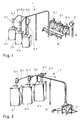
- a first variant of a system according to the invention for conveying moist comminuted tobacco material is shown.
- This system comprises three tobacco dispensers 10.1 to 10.3, each having a funnel-shaped container that tapers downwardly.
- Each of the tobacco dispensing devices 10.1 to 10.3 is connected to a respective tobacco conveying tube 12.1 to 12.3, which are guided in parallel over a distance.
- the three tobacco conveying pipes 12.1 to 12.3 are divided downstream and run to tobacco receiving devices 14.1 to 14.3, each of which is followed by a bag filling machine 16.1 to 16.3.
- the Tabaksendevoriquesen 10.1 to 10.3 are fed with wet shredded tobacco material, promote this towards the tobacco conveying pipes 12.1 to 12.3, through which they are conveyed to the tobacco receiving devices 14.1 to 14.3 by intermittent cyclic air ruptures, which prevent recapping of the tobacco material.
- the piping of the system 1 may be several tens of meters, for example up to 50 or 100 meters long.
- Fig. 1 To fill the Tabaksendevoriquesen 10.1 to 10.3 are two different ways in Fig. 1 shown. For a manual Filling is available to an operator an operator pedestal 18, which provides him access to the top of Tabaksendevoriquesen 10.1 to 10.3. For machine-assisted or automatic filling, a system of a trolley 19 mounted on a lifting column 20 is provided. The trolley 19 can be filled with tobacco and raised with the lifting column 20, wherein the trolley 19 is then emptied into the respective tobacco end device 10.1 to 10.3.
- a large tobacco-dispensing device 11 supplies three tobacco-receiving receiving devices 14.1 to 14.3 via three tobacco-conveying tubes 12.1 to 12.3, which can be configured as the tobacco-sending devices 14.1 to 14.3 and subsequently supplied with three bag filling machines 16.1 to 16.3.
- the tobacco conveying tubes 12.1 to 12.3 are guided parallel to a switch 13, in the switch 13 they then branch off to the various tobacco receiving devices 14.1 to 14.3 and bag filling machines 16.1 to 16.3.
- This system allows a large-volume feed of several tobacco receiving devices 14.1 to 14.3 from a single tobacco end device 11, while the system 1 of Fig. 1 For example, the promotion of different varieties of tobacco material allows.
- a tobacco dispenser 10 On a lower floor level, a hall floor 5, a tobacco dispenser 10 is positioned, which has a funnel-shaped container 30 which is placed on a tripod frame 31. On its upper side, the funnel-shaped container 30 has a lid 32 and a stirrer drive 34. The stirrer is in Fig. 3 not shown.
- the funnel-shaped container 30 merges into a tobacco outlet 36, which is connected via a controllable valve 38 to a tobacco conveying tube 12.
- the conveying direction is shown with arrows in the tobacco conveying pipe 12.
- the tobacco conveying pipe 12 terminates at a tobacco receiving device 14 which is mounted on a machine roof or a machine roof level 6.
- the tobacco receiving device 14 is designed in the form of a vacuum container 22 in which the tobacco material enters via a connecting piece for the tobacco conveying tube in a peripheral or tangential and slightly inclined manner.
- At the bottom of an outlet not shown in detail is arranged, through which the received tobacco material exits and passes to a bag filling machine, not shown.
- a vacuum line 26 sets, which is fed by a vacuum pump 24.
- a negative pressure is generated by means of the vacuum pump 24 in the vacuum container 22 and in the tobacco conveying pipe 12 when the controllable valve 38 is closed.
- the valve 38 is opened, the vacuum pump 24 can stop generating the negative pressure and by balancing the negative pressure creates an air flow from the tobacco outlet 36 of the tobacco dispenser 10 through the tobacco conveyor tube 12 into the vacuum container 22, by the reception of the Tobacco falls down and the air escapes.
- Fig. 4 shows the system 1 according to Fig. 3 during a rinse.
- a rinsing liquid for example, warm water
- a rinsing liquid for example, warm water
- the rinsing liquid collects in the funnel-shaped container 30
- the vacuum pump 24, the via a vacuum line 28 and a valve 29 is now connected to a mobile wastewater tank 42, employed in the mobile wastewater tank 42 generates a negative pressure and via a purge line 44, which is connected to the lower end of the vacuum container 22, the flushing liquid aspirated, including the rinsing liquid that has accumulated in the tobacco sending device 10.
- This can also be sucked through the tobacco conveyor tube 12, which is cleaned at the same time.
- a mechanical cleaning of the tobacco conveying pipe by means of a pipe cleaning plug can be done.
- an electrically driven blower can be used for drying.
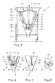
- Fig. 5 the funnel-shaped container 30 of the tobacco end device 10 is shown in cross-section.
- the funnel wall 33 extends from the top wide down to close.
- a stirring beam 130 is arranged, which has a central axis 131 around which the stirring beam 130 rotates. From the central axis 131, upper cantilever arms 132 and lower cantilever arms 133 branch off, holding the doctor beams 135, 136.
- the doctor carriers 135, 136 are rods whose inclination corresponds to the inclination of the funnel wall 33, and arranged at a defined distance from the funnel wall 33.
- Each of these scraper carriers 135, 136 carries a plurality of wall scrapers 137, the task of which is to remove moist comminuted tobacco material from the funnel wall 33 and allow it to trickle downwards.
- the stirring beam 130 has at its lower end a closure piece 134 which is aligned perpendicular to the central axis 131, and at which also the scraper carrier 135, 136 end.
- This end piece 134 also has a scraper, namely a screen scraper 138, which has an L-shaped surface.
- This screen scraper 138 sets with its lower scraper edge on a Sieve 35, which separates the interior, which separates with the stirring beam 130 from a lower cavity 37, followed by the tobacco outlet 36.
- the sieve 35 can also be designed as a perforated plate.
- the screen scraper 138 also has a shorter side piece which has a scraper edge scraping against the funnel wall 33.
- the screen 35 which may also be a perforated plate, in the direction of the tobacco outlet 36th
- Fig. 7 is the lower part according to Fig. 6 shown in a side cross-sectional view.
- a scraper holder 140 which is angled, wherein on the angled piece of screen scraper 138 is arranged, the scraper edge is also shown.
- the scraper edge is pressed against the screen 35.
- Two screen scrapers 138 can also be arranged on the two sides of the end piece 134.
- FIG. 3 is a partial top plan view of a portion of the funnel wall 33, together with a cross-section through a scraper carrier 135 on which a scraper holder 139 with a wall scraper 137 is disposed.
- the scraper holder 139 has an axis that allows easy rotation of the wall scraper 137 about the axis. Through the through the tobacco material the pressure exerted as the rotation traverse 130 rotates, the wall scraper 137 is pressed against the inner wall of the funnel wall 33 in this case as well.
- a tobacco receiving device 14 is shown schematically in cross-section.
- This is a vacuum container 22 having an upper part 52 and a lower part 50, which are connected to one another at a connection point by means of a connecting ring and a sealing ring or connected.
- a filter grid 68 and a perforated plate 70 which separate an upper subspace from a lower subspace.
- a 360 ° CIP spray nozzle 40 which serves to clean the vacuum tank 22, and connections 60 for compressed air, 62 for rinsing liquid and 58 for suction.
- a port 64 for a safety valve As in Fig. 9b ) is shown in plan view, there is also a port 64 for a safety valve.
- FIG. 9a illustrated lower subspace of the vacuum vessel 22 opens peripherally and in a direction obliquely downward pointing a port 66 for a tobacco pipe.
- a port 66 for a tobacco pipe As the air tobacco material stream from port 66 enters the vacuum vessel 22 tangentially, it acts substantially like a cyclone.
- a lock 72 With a gate valve 74, which is shown in a passage position and in a closed position one above the other. At any one time, only one of these two positions will be taken.
- the lock 74 is followed by a tobacco discharge funnel 76 through which received tobacco material to another station, such as a bag filling machine, is directed.
- FIG. 9c A perforated plate 70 is shown, which closes the upper part of the lower space of the vacuum chamber 22 and allows passage of air.
Abstract
Description
Die Erfindung betrifft ein System zum Fördern von zerkleinertem Tabakmaterial mit einem Feuchtegehalt von 35% oder mehr, eine Tabaksendevorrichtung und ein Verfahren zum Fördern von zerkleinertem Tabakmaterial mit einem Feuchtegehalt von 35% oder mehr.The invention relates to a system for conveying comminuted tobacco material having a moisture content of 35% or more, a tobacco dispenser and a method for conveying comminuted tobacco material having a moisture content of 35% or more.
Unter zerkleinertem Tabakmaterial mit einem Feuchtegehalt von 35% oder mehr wird im Rahmen der vorliegenden Anmeldung insbesondere ein gemahlener oder geschnittener Tabak mit einem hohen Feuchtigkeitsgehalt verstanden.By shredded tobacco material with a moisture content of 35% or more is meant in the context of the present application, in particular a ground or cut tobacco with a high moisture content.
Als Tabakmaterial kommen somit gemahlener oder geschnittener Tabak sowie ggf. Zusätze infrage. Die Schnittlänge ist dabei so kurz, dass das geschnittene feuchte Tabakmaterial eine vergleichbare Konsistenz hat wie gemahlenes feuchtes Tabakmaterial. Ein solches feuchtes gemahlenes oder geschnittenes Tabakmaterial wird unter anderem als sogenannter SNUS-Tabak bzw. rauchloser Tabak angeboten und wird oral, d.h. in der Mundhöhle, verwendet. SNUS-Tabak hat eine Feuchtigkeit von etwa 35% bis 50% oder mehr und ist eine feinkörnige, klumpige Substanz, die in der Konsistenz feuchtem Kaffeesatz ähnlich ist.As a tobacco material thus ground or cut tobacco and possibly additives come into question. The cut length is so short that the cut moist tobacco material has a similar consistency as ground moist tobacco material. Such a moist ground or cut tobacco material Among other things, it is offered as so-called SNUS tobacco or smokeless tobacco and is used orally, ie in the oral cavity. SNUS tobacco has a moisture content of about 35% to 50% or more and is a fine-grained, lumpy substance that is similar in consistency to wet coffee grounds.
Zum Konsumieren ist SNUS-Tabak in einigen Fällen mit Geschmacksstoffen versetzt, beispielsweise Menthol, Salmiak oder anderen Geschmacksstoffen, und wird in Portionen von 0,5 bis 2 Gramm in sogenannte SNUS-Beutel verpackt. Hierbei handelt es sich um ein poröses Papier, die sogenannte "Pouch", die rundum versiegelt ist, aber wasserdurchlässig ist und die Inhaltsstoffe der "Pouch" in den Mundbereich und die Schleimhäute des Mundes abgibt. Die häufigste Portionsgröße ist ca. ein Gramm pro Portion. Nach dem Konsumieren der "Pouch" wird dieser aus dem Mund entnommen und entsorgt.For consumption, SNUS tobacco is in some cases flavored with, for example, menthol, sal ammoniac or other flavoring agents, and is packaged in portions of 0.5 to 2 grams in so-called SNUS bags. This is a porous paper, the so-called "pouch", which is completely sealed, but permeable to water and releases the ingredients of the "pouch" in the mouth and the mucous membranes of the mouth. The most common portion size is about one gram per serving. After consuming the "pouch" this is taken out of the mouth and disposed of.
Wie feuchter Kaffeesatz auch, klumpt das feuchte, zerkleinerte Tabakmaterial des SNUS-Tabaks, was besondere Verarbeitungsverfahren notwendig macht. So werden die Maschinen, mit denen die SNUS-Beutel hergestellt werden, bislang per Hand mit dem zerkleinerten, feuchten Tabakmaterial beschickt, das zuvor in großen Kühlräumen in Behältern gekühlt aufbewahrt worden ist. Die Behälter, in denen das feuchte, zerkleinerte Tabakmaterial aufbewahrt wird, sind abgedeckt, damit die Feuchtigkeit des Tabakmaterials nicht entweicht. Auch während des Transports zu den Portionierungsmaschinen ist darauf zu achten, dass das Material nicht austrocknet und sich möglichst wenig erwärmt.Like moist coffee grounds, the moist, shredded tobacco material of SNUS tobacco clumps, which requires special processing methods. Thus, the machines used to manufacture the SNUS pouches have hitherto been fed by hand with the shredded, moist tobacco material which has previously been kept refrigerated in containers in large refrigerated spaces. The containers in which the moist, shredded tobacco material is stored, are covered so that the moisture of the tobacco material does not escape. During transport to the portioning machines, care must be taken to ensure that the material does not dry out and heats up as little as possible.
Diese Vorgehensweise ist sehr aufwändig. Aufgrund des bei der Herstellung der SNUS-Beutel entstehenden Lärms und der intensiven Geruchsbelastung durch das zerkleinerte feuchte Tabakmaterial stellt diese Vorgehensweise auch eine starke Belastung für die Arbeiter dar, die dieses manuelle Beschicken der Portionierungsvorrichtungen ausüben.This procedure is very complicated. Due to the noise generated during the production of the SNUS bags and the intensive odor load caused by the shredded moist tobacco material This approach also places a heavy burden on the workers performing this manual loading of the portioning devices.
Ein automatisierter Transport des feuchten, zerkleinerten Tabakmaterials findet derzeit nicht statt, da dieses Material sich aufgrund seiner schweren, klumpigen Konsistenz nicht für einen automatisierten Transport mit herkömmlichen Mitteln, wie bei pneumatischer Förderung, eignet, wie sie bei trockenem Tabakmaterial mit größerer Oberfläche, wie sie für Zigaretten beispielsweise verwendet wird, bekannt ist. Dieses Material bietet dem kontinuierlichen Luftstrom in einem pneumatischen Fördersystem eine große Angriffsfläche, so dass dieses trockene Tabakmaterial auch pneumatisch gefördert wird. Ein entsprechendes System zur pneumatischen Förderung von trockenem Tabak, der nicht sehr fein zerkleinert ist, ist beispielsweise aus
Demgegenüber liegt der vorliegenden Erfindung die Aufgabe zugrunde, ein System, Systemkomponenten und ein Verfahren zum Fördern von feuchtem, zerkleinerten Tabakmaterial zur Verfügung zu stellen, mit denen die Konsistenz des feuchten Tabakmaterials erhalten bleibt und eine automatische Förderung ohne starke Belastung von Personen ermöglicht wird.In contrast, the present invention has the object to provide a system, system components and a method for conveying moist, shredded tobacco material available, with which the consistency of the wet tobacco material is maintained and an automatic promotion is possible without heavy burden on people.
Diese Aufgabe wird gelöst durch ein System zum Fördern von zerkleinertem Tabakmaterial mit einem Feuchtegehalt von 35% oder mehr, umfassend wenigstens eine Tabaksendevorrichtung und wenigstens eine Tabakempfangsvorrichtung, die mittels wenigstens eines druckdichten Tabakförderrohres miteinander verbunden sind, eine Steuervorrichtung und ein durch die Steuervorrichtung steuerbares Verschlusselement, mittels dessen eine Verbindung der Tabaksendevorrichtung zum Tabakförderrohr verschließbar ist, sowie eine Luftabsaugvorrichtung, mittels deren ein Unterdruck in dem Tabakförderrohr erzeugbar ist, wobei die Steuervorrichtung ausgebildet ist, das Verschlusselement zum Aufbau von Unterdruck im Tabakförderrohr zu schließen und nach erfolgtem Aufbau von Unterdruck zur Förderung von Tabakmaterial durch das Tabakförderrohr zu öffnen.This object is achieved by a system for conveying comminuted tobacco material with a moisture content of 35% or More, comprising at least one tobacco end device and at least one tobacco receiving device, which are interconnected by means of at least one pressure-tight tobacco conveying tube, a control device and a controllable by the control device closure element, by means of which a connection of the tobacco end device to the tobacco conveyor tube is closable, and an air suction device, by means of which a negative pressure in the tobacco conveying pipe is producible, wherein the control device is designed to close the closure element to build up negative pressure in the tobacco conveying pipe and to open after the build-up of negative pressure for conveying tobacco material through the tobacco conveying pipe.
Die Erfindung beruht auf dem Grundgedanken, dass ein Fördersystem für zerkleinertes Tabakmaterial mit einem hohen Feuchtegehalt eine zyklisch intermittierende Förderung des feuchten, zerkleinerten Tabakmaterials bereitstellt. Hierzu werden eine oder mehrere Tabaksendevorrichtungen und eine oder mehrere Tabakempfangsvorrichtungen zur Verfügung gestellt, die mittels eines oder mehrerer druckdichter Tabakförderrohre miteinander verbunden sind. In den Tabakförderrohren wird, solange die Verbindung zur Tabaksendevorrichtung verschlossen ist, ein Unterdruck aufgebaut, beispielsweise zwischen 100 hPa und 300 hPa, wobei außer der Luftabsaugung kein Luftstrom in dem Tabakförderrohr entsteht. Nach Erreichen eines voreingestellten oder voreinstellbaren Unterdrucks in dem Tabakförderrohr wird die Verbindung zur Tabaksendevorrichtung geöffnet, so dass feuchtes, zerkleinertes Tabakmaterial in das mit Unterdruck beaufschlagte Tabakförderrohr hineingesaugt wird und durch dieses hindurch transportiert wird. Bei dem Druckausgleich stellt sich ein Luftstrom ein, der von der Tabaksendevorrichtung in Richtung auf die Tabakempfangsvorrichtung gerichtet ist. Da es sich nicht um einen umlaufenden Luftstrom handelt, wie in anderen pneumatischen Fördersystemen, ist dieser Luftstrom nicht erwärmt, sondern entspricht der Umgebungsluft, so dass ein Austrocknen des feuchten Tabakmaterials effektiv verhindert wird.The invention is based on the basic idea that a conveyor system for shredded tobacco material with a high moisture content provides a cyclically intermittent delivery of the moist, shredded tobacco material. For this purpose, one or more Tabaksendevorrichtungen and one or more tobacco receiving devices are provided, which are interconnected by means of one or more pressure-tight tobacco delivery tubes. As long as the connection to the tobacco-dispensing device is closed, a negative pressure is built up in the tobacco-conveying tubes, for example between 100 hPa and 300 hPa, with no air flow occurring in the tobacco-conveying tube except for the air suction. After reaching a preset or presettable negative pressure in the tobacco conveying pipe, the connection to the tobacco sending device is opened, so that wet, shredded tobacco material is sucked into the vacuum-loaded tobacco conveying tube and transported therethrough. In the pressure equalization adjusts an air flow, which is directed by the tobacco end device in the direction of the tobacco receiving device. Because it is not a circulating airflow, as in others pneumatic conveying systems, this air flow is not heated, but corresponds to the ambient air, so that drying out of the moist tobacco material is effectively prevented.
Es wurde festgestellt, dass mit jedem Zyklus des intermittierenden Druckausgleichs das Tabakmaterial einen Weg von mehreren Metern innerhalb des Tabakförderrohrs zurücklegen kann, wobei nur sehr wenig Material an der Tabakförderrohrwand anhaftet und zurückbleibt. Der Verlust an Tabakmaterial ist somit minimal. Dies hängt auch mit der intermittierenden Betriebsweise zusammen, die durch Druckstöße und Luftschwälle ein Zusammenklumpen von Material an der Rohrwand minimiert.It has been found that with each cycle of intermittent pressure equalization, the tobacco material can travel a distance of several meters within the tobacco conveying tube, with very little material adhering and remaining to the tobacco conveying tube wall. The loss of tobacco material is thus minimal. This is also related to the intermittent mode of operation which minimizes agglomeration of material on the pipe wall by pressure surges and air ripples.
Vorzugsweise ist mittels der Steuervorrichtung und der Laufabsaugvorrichtung zyklisch abwechselnd bei verschlossener Verbindung zwischen Tabaksendevorrichtung und Tabakförderrohr der Unterdruck im Tabakförderrohr erzeugbar und nach Erreichen eines voreingestellten oder voreinstellbaren Unterdrucks im Tabakförderrohr bei Öffnung der Verbindung zur Tabaksendevorrichtung ist ein Druckausgleich mit einem Luftstromschub zur Tabakempfangsvorrichtung erzeugbar. Damit ist die bevorzugte intermittierende Betriebsweise des Systems durch die Steuervorrichtung und die Luftabsaugvorrichtung gewährleistet.Preferably, by means of the control device and the Laufabsaugvorrichtung cyclically alternately with a sealed connection between the tobacco dispenser and tobacco conveyor tube, the negative pressure in the tobacco conveyor tube generated and after reaching a preset or presettable negative pressure in the tobacco conveyor tube when opening the connection to the tobacco end delivery device, a pressure compensation with an air flow thrust to the tobacco receiving device can be generated. Thus, the preferred intermittent operation of the system is ensured by the control device and the Luftabsaugvorrichtung.
Vorzugsweise weist das Tabakförderrohr im Bereich der Tabaksendevorrichtung einen, insbesondere steuerbaren, Nebenlufteingang auf. Damit ist unabhängig von der Befüllung der Tabaksendevorrichtung mit feuchtem Tabak ein genau bestimmbarer Luftstrom im Druckausgleichszyklus gewährleistet.The tobacco conveying tube preferably has a, in particular controllable, auxiliary air inlet in the region of the tobacco sending device. This ensures a precisely determinable air flow in the pressure equalization cycle, regardless of the filling of the tobacco dispenser with wet tobacco.
Vorteilhafterweise weist die wenigstens eine Tabakempfangsvorrichtung einen druckdicht verschließbaren Ausgang auf. Der druckdicht verschließbare Ausgang unterstützt das System ebenfalls dabei, einen Unterdruck im Tabakförderrohr einstellen zu können.Advantageously, the at least one tobacco receiving device has a pressure-tight sealable output. The pressure-tight lockable outlet also helps the system to adjust a negative pressure in the tobacco pipe.
In der Tabakempfangsvorrichtung wird das feuchte, zerkleinerte Tabakmaterial von dem Luftstrom getrennt. Dies kann in Form eines Luftabscheiders, beispielsweise eines Zyklons oder eines Vakuumbehälters, geschehen, bei dem beispielsweise das Tabakmaterial durch die Schwerkraft eingezogen nach unten fällt, während die Luft in eine andere Richtung, beispielsweise nach oben, entweicht.In the tobacco receiving device, the wet, shredded tobacco material is separated from the air flow. This may be in the form of an air separator, for example a cyclone or a vacuum container, in which, for example, the tobacco material is pulled down by gravity while the air escapes in another direction, for example upwards.
Vorzugsweise ist die wenigstens eine Tabakempfangsvorrichtung Teil einer Beutelabfüllmaschine oder zur Übergabe von empfangenem Tabakmaterial an eine Beutelabfüllmaschine bei der Beutelabfüllmaschine angeordnet und/oder mit der Beutelabfüllmaschine verbunden. Damit ist das erfindungsgemäße System zum Fördern von zerkleinertem, feuchten Tabakmaterial unmittelbar angebunden an eine Beutelabfüllmaschine, die die üblicherweise verwendeten Portionsbeutel für unter anderem SNUS-Tabak herstellt, oder ein Teil des Systems ist in eine solche Beutelabfüllmaschine integriert.Preferably, the at least one tobacco receiving device is part of a bag filling machine or for transferring received tobacco material to a bag filling machine at the bag filling machine and / or connected to the bag filling machine. Thus, the inventive system for conveying shredded, wet tobacco material is directly attached to a bagging machine that makes the commonly used sachets for, inter alia, SNUS tobacco, or part of the system is integrated into such a bag filling machine.
In einer vorteilhaften Ausbildung des erfindungsgemäßen Systems ist eine Mehrzahl von Tabaksendevorrichtungen umfasst, die über eine Mehrzahl von Tabakförderrohren mit einer Mehrzahl von Tabakempfangsvorrichtungen verbunden sind, oder wenigstens eine Tabaksendevorrichtung ist über mehrere Tabakförderrohre, insbesondere über eine Weiche, mit mehreren Tabakempfangsvorrichtungen verbunden. In der ersten Alternative ist es möglich, verschiedene Sorten von feuchtem und zerkleinertem Tabakmaterial parallel zueinander zur fördern und in getrennten Beutelabfüllmaschinen in Portionsbeutel abzufüllen. In der zweiten Alternative können aus einer großen Tabaksendevorrichtung eine Mehrzahl von Tabakempfangsvorrichtungen beschickt werden.In an advantageous embodiment of the system according to the invention, a plurality of tobacco dispensing devices is connected to a plurality of tobacco receiving devices via a plurality of tobacco conveying tubes, or at least one tobacco dispensing device is connected to a plurality of tobacco receiving devices via a plurality of tobacco conveying tubes, in particular via a switch. In the first alternative, it is possible to convey different types of moist and shredded tobacco material parallel to each other and to fill in sachets in separate bag filling machines. In the second alternative, a plurality of tobacco receiving devices may be charged from a large tobacco dispenser.
Zum Befüllen der Tabaksendevorrichtung oder Tabaksendevorrichtungen ist vorzugsweise vorgesehen, dass ein Operator-Podest zur manuellen Befüllung an der Tabaksendevorrichtung angeordnet ist und/oder eine Hubsäulen-Trolley-Kombination. Das Operator-Podest ermöglicht eine manuelle Befüllung, bei der eine Bedienperson, der Operator, die Tabaksendevorrichtung von Hand mit dem feuchten, zerkleinerten Tabakmaterial beschickt. In der Variante mit Hubsäulen-Trolley-Kombination kann dies durch mechanische und motorbetriebene Mittel wie Hubsäulen und Trolleys unterstützt werden, die auch automatisiert sein können.For filling the tobacco end device or tobacco end devices it is preferably provided that an operator pedestal for manual filling is arranged on the tobacco end device and / or a lifting column trolley combination. The operator pedestal allows manual filling in which an operator, the operator, manually feeds the tobacco dispenser with the wet, shredded tobacco material. In the variant with lifting column trolley combination, this can be supported by mechanical and motorized means such as lifting columns and trolleys, which can also be automated.
Um eine Anhaftung von Tabakmaterial von der Konsistenz von feuchtem Kaffeesatz zu verhindern, kann weiterer Aufwand getrieben werden. So können die Komponenten und insbesondere das Tabakförderrohr aus einem blank polierten Edelstahl, beispielsweise V4A-Edelstahl, bestehen, der ein austenitischer Edelstahl sein kann. Dieser bietet besonders wenig Affinität zur Anhaftung. Die Oberflächen sind vorzugsweise elektropoliert, daher besonders glatt und stoßfrei.To prevent adhesion of tobacco material of the consistency of wet coffee grounds, further effort can be driven. Thus, the components, and in particular the tobacco conveying tube, may consist of a brightly polished stainless steel, for example V4A stainless steel, which may be an austenitic stainless steel. This has very little affinity for attachment. The surfaces are preferably electropolished, therefore particularly smooth and bumpless.
In einer vorteilhaften Weiterbildung ist ein Spülsystem umfasst, mittels dessen die wenigstens eine Tabaksendevorrichtung und/oder das wenigstens eine Tabakförderrohr und/oder die wenigstens eine Tabakempfangsvorrichtung spülbar sind, wobei das Spülsystem eine Spülflüssigkeitszuführung und eine Spülflüssigkeitsabführung bzw. Spülleitung aufweist, wobei Spritzdüsen, insbesondere 360°-CIP-Düsen, in der Tabaksendevorrichtung und/oder in der Tabakempfangsvorrichtung angeordnet oder einbringbar sind, wobei insbesondere weiter ein Rohrreinigungsstopfen zur Rohrreinigung und/oder Rohrtrocknung und/oder ein elektrisch angetriebenes Gebläse zur Trocknung umfasst ist oder sind. CIP-Düsen (Clean-In-Place-Düsen) sind in der Lage, Spülflüssigkeit, insbesondere warmes Wasser, in alle Richtungen zu sprühen, um einen Innenraum effektiv zu reinigen. Mit diesen Spritzdüsen ist eine automatische Reinigung des Systems möglich. Dabei können die Spritzdüsen in der oder den Tabaksendevorrichtung(en) und/oder in der oder den Tabakempfangsstation(en) angeordnet sein.In an advantageous development, a flushing system is included, by means of which the at least one tobacco end device and / or the at least one tobacco conveying tube and / or the at least one tobacco receiving device can be flushed, the flushing system having a flushing liquid inlet and a flushing liquid outlet or flushing line, wherein spray nozzles, in particular 360 ° CIP nozzles are arranged or can be introduced in the tobacco dispenser and / or in the tobacco receiving device, wherein in particular further comprises a pipe cleaning plug for pipe cleaning and / or pipe drying and / or an electrically driven blower for drying is or are included. CIP nozzles (Clean-In-Place nozzles) are able to spray rinsing liquid, in particular warm water, in all directions to effectively clean an interior space. These spray nozzles allow automatic cleaning of the system. In this case, the spray nozzles in the tobacco or the tobacco end device (s) and / or in the or the tobacco receiving station (s) may be arranged.
Um die Spülflüssigkeit nach dem Spülen wieder abzuführen, ist vorzugsweise vorgesehen, dass zur Absaugung von Spülflüssigkeit die Tabakempfangsvorrichtung mit einer mit einem Unterdruck beaufschlagbaren Spülleitung verbunden oder verbindbar ist. Hierdurch wird die Spülflüssigkeit aus dem System abgesaugt und beispielsweise in einem mobilen Behälter für die abgesaugte Spülflüssigkeit gebracht. Die Absaugung kann auch aus Tabaksendevorrichtung und Tabakempfangsvorrichtung getrennt erfolgen.In order to remove the rinsing liquid again after rinsing, it is preferably provided that the tobacco receiving device can be connected or connectable to a rinsing line which can be acted upon by a negative pressure for the purpose of suctioning out rinsing liquid. As a result, the rinsing liquid is sucked out of the system and brought, for example, in a mobile container for the extracted rinsing liquid. The suction can also be done separately from the tobacco dispenser and the tobacco receiving device.
Zusätzlich kann ein elektrisch angetriebenes Gebläse als Fön zum Abschluss eines Reinigungsvorgangs verwendet werden.In addition, an electric blower can be used as a hair dryer to complete a cleaning process.
Die der Erfindung zugrunde liegende Aufgabe wird auch durch eine Tabaksendevorrichtung, insbesondere für ein zuvor beschriebenes erfindungsgemäßes System, zum Fördern von zerkleinertem Tabakmaterial mit einem Feuchtegehalt von 35% oder mehr, gelöst, wobei ein sich in Gravitationsrichtung verjüngender trichterförmiger Behälter umfasst ist, der von oben mit Tabakmaterial beschickbar ist, wobei im Behälter eine Rührwerkstraverse mit Schabern angeordnet ist, die gegen eine Trichterwand des Behälters gerichtet sind, wobei der Behälter an seinem unteren Ende wenigstens einen Tabakauslass zum Anschluss eines druckdichten Tabakförderrohrs aufweist, wobei insbesondere die Schaber gelenkig an der Rührwerkstraverse unter einem Winkel zur Trichterwand angeordnet sind, so dass die Schaber beim Rühren durch den Widerstand des Tabakmaterials an die Trichterwand gedrückt werden.The object underlying the invention is also achieved by a tobacco end device, in particular for a previously described inventive system, for conveying shredded tobacco material having a moisture content of 35% or more, wherein a gravitationally tapered funnel-shaped container is included, from above can be fed with tobacco material, wherein in the container a Rührwerkstraverse is arranged with scrapers, which are directed against a funnel wall of the container, the container having at its lower end at least one tobacco outlet for connecting a pressure-tight tobacco conveying tube, in particular the scraper hinged to the Rührwerkstraverse below are arranged at an angle to the funnel wall, so that the scrapers when stirring by the resistance of the Tobacco material are pressed to the funnel wall.
Diese erfindungsgemäße Tabaksendevorrichtung ist geeignet, das feuchte, zerkleinerte Tabakmaterial mit seiner kaffeesatzähnlichen Konsistenz vorzuvereinzeln, indem durch Schaber das Tabakmaterial gerührt und weitertransportiert wird und insbesondere von der Trichterwand abgekratzt wird. Durch die Schwerkraft gezogen fällt das Tabakmaterial nach unten in Richtung auf das angeschlossene Tabakförderrohr.This tobacco dispenser according to the invention is suitable for vorzuvereinzeln the wet, shredded tobacco material with its coffee grounds similar consistency by the tobacco material is stirred by scrapers and transported further and in particular is scraped off the funnel wall. Pulled by gravity, the tobacco material falls down in the direction of the connected tobacco conveyor tube.
Vorzugsweise ist in einem unteren Teil des Behälters ein Sieb oder eine Lochplatte angeordnet und die Rührwerkstraverse mit den Schabern oberhalb des Siebs oder der Lochplatte angeordnet, wobei wenigstens ein Schaber der Rührwerkstraverse gegen das Sieb oder die Lochplatte gerichtet ist, wobei insbesondere der Schaber gelenkig an der Rührwerkstraverse unter einem Winkel zum Sieb oder zur Lochplatte angeordnet ist, so dass der Schaber beim Rühren durch den Widerstand des Tabakmaterials an das Sieb oder die Lochplatte gedrückt wird. Die Kombination eines Schabers auf einer Lochplatte oder einem Sieb bewirkt eine noch effektivere Vorvereinzelung des kaffeesatzähnlichen Tabakmaterials, so dass das Tabakmaterial nach Durchqueren des Siebs bzw. der Lochplatte in bereits stark vereinzelter Form in Richtung auf das Tabakförderrohr rieselt und effektiv durch den intermittierenden Luftstrom mitgerissen wird.Preferably, a sieve or a perforated plate is arranged in a lower part of the container and arranged the Rührwerkstraverse with the scrapers above the screen or the perforated plate, wherein at least one scraper of Rührwerkstraverse is directed against the sieve or the perforated plate, in particular the scraper hinged to the Agitator is arranged at an angle to the screen or the perforated plate, so that the scraper is pressed during stirring by the resistance of the tobacco material to the sieve or the perforated plate. The combination of a scraper on a perforated plate or a sieve causes even more effective preliminary separation of the coffee grounds tobacco material, so that the tobacco material trickles after crossing the sieve or the perforated plate in already strongly isolated form in the direction of the tobacco conveyor tube and is effectively entrained by the intermittent air flow ,
Die Schaber können beispielsweise aus Polyethylen bestehen.The scrapers may for example consist of polyethylene.
Bei der erfindungsgemäßen Tabaksendevorrichtung sind vorzugsweise zur Reinigung des Behälters Spritzdüsen, insbesondere 360°-CIP-Düsen, unter einem, insbesondere abnehmbaren, Deckel angeordnet. Damit ist die Tabaksendevorrichtung gut reinigbar.In the tobacco dispenser according to the invention are preferably for cleaning the container spray nozzles, in particular 360 ° CIP nozzles, under a, in particular removable, lid arranged. Thus, the tobacco end device is easy to clean.
Die der Erfindung zugrunde liegende Aufgabe wird auch durch ein Verfahren zum Fördern von zerkleinertem Tabakmaterial mit einem Feuchtegehalt von 35% oder mehr, insbesondere in einem erfindungsgemäßen zuvor beschriebenen System, gelöst, wobei das Tabakmaterial in wenigstens einer Tabaksendevorrichtung zu wenigstens einem mit wenigstens einem druckdichten Tabakförderrohr, verbundenen Tabakauslass gefördert wird, wobei die Verbindung gesteuert verschließbar ist und das wenigstens eine Tabakförderrohr weiter mit wenigstens einer Tabakempfangsvorrichtung verbunden ist, wobei zyklisch abwechselnd die folgenden Verfahrensschritte ausgeführt werden:
- die Verbindung zwischen Tabakauslass der Tabaksendevorrichtung und Tabakförderrohr wird geschlossen und im Tabakförderrohr ein Unterdruck erzeugt,
- nach Erreichen eines vorbestimmten oder vorbestimmbaren Unterdrucks in dem Tabakförderrohr wird die Verbindung zwischen Tabakauslass und Tabakförderrohr geöffnet, wodurch Tabakmaterial durch das Tabakförderrohr gesaugt wird, insbesondere unter Zuführung von Nebenluft in das Tabakförderrohr.
- the connection between the tobacco outlet of the tobacco-dispensing device and the tobacco-conveying tube is closed and a negative pressure is created in the tobacco-conveying tube,
- after reaching a predetermined or predeterminable negative pressure in the tobacco conveying pipe, the connection between the tobacco outlet and the tobacco conveying pipe is opened, whereby tobacco material is sucked through the tobacco conveying pipe, in particular by supplying secondary air into the tobacco conveying pipe.
Dieses erfindungsgemäße Verfahren beinhaltet das zyklische Abwechseln von Erzeugen von Unterdruck im Tabakförderrohr und nach Erreichen des gewünschten Unterdrucks von einigen hundert hPa unterhalb des Umgebungsluftdrucks zum Herstellen eines Druckausgleichs das Öffnen der Verbindung zwischen Tabaksendevorrichtung und Tabakförderrohr, wodurch beim Druckausgleich im Tabakförderrohr ein Ausgleichsluftsog entsteht, der Tabakmaterial aus der Tabaksendevorrichtung in das Tabakförderrohr in Richtung auf die Tabakempfangsvorrichtung zu mitreißt. Dies gilt ebenso für den Fall, dass mehrere Tabaksendevorrichtungen und/oder mehrere Tabakempfangsvorrichtungen mit entsprechenden Tabakförderrohren vorhanden sind, für jedes Tabakförderrohr einzeln.This method according to the invention involves the cyclic alternation of generating negative pressure in the tobacco conveying tube and after reaching the desired negative pressure of a few hundred hPa below the ambient air pressure to establish a pressure equalization the opening of the connection between the tobacco dispenser and tobacco conveyor tube, whereby a compensating air suction, the tobacco material is created during pressure equalization in the tobacco conveyor tube from the tobacco dispenser in the tobacco conveyor tube in the direction entraining the tobacco receiving device. This also applies to the case where there are several tobacco-sending devices and / or several tobacco-receiving devices with corresponding tobacco-conveying tubes, for each tobacco-conveying tube individually.
Vorzugsweise wird das Tabakmaterial in der Tabaksendevorrichtung soweit aufgelockert und/oder vereinzelt, dass es in einem oder mehreren Zyklen von Saugluft im Tabakförderrohr zur Tabakempfangsvorrichtung mitgerissen wird.Preferably, the tobacco material in the tobacco dispenser is loosened and / or singulated so far that it is entrained in one or more cycles of suction air in the tobacco conveying tube to the tobacco receiving device.
Wenn das Tabakmaterial, das durch das Tabakförderrohr zur Tabakempfangsvorrichtung gesaugt wurde, zu einer Beutelabfüllmaschine weitergefördert wird, ist das erfindungsgemäße Förderverfahren für das zerkleinerte, feuchte Tabakmaterial direkt an die Abfüllung in Portionsbeutel angebunden.When the tobacco material sucked through the tobacco conveying tube to the tobacco receiving device is conveyed to a bag filling machine, the conveying method for the crushed wet tobacco material according to the present invention is directly connected to the filling into sachets.
Es können vorteilhafterweise mehrere Tabakförderrohre unabhängig voneinander betrieben werden, oder, insbesondere wenn nur wenig Kapazität zur Erzeugung von Unterdrücken vorhanden ist, wird jeweils nur eines von mehreren Tabakförderrohren zu einer Tabaksendevorrichtung geöffnet. Der erste Fall geht davon aus, dass die Tabakförderrohre tatsächlich unabhängig voneinander betrieben werden und beispielsweise jeweils eine Luftabsaugvorrichtung zur Verfügung haben, während im zweiten Fall beispielsweise eine Luftabsaugvorrichtung zur Luftabsaugung in mehreren verschiedenen Tabakförderrohren verwendet wird. Im letzteren Fall stellt die Maßnahme, nur jeweils eine Verbindung zu einer Tabaksendevorrichtung zu öffnen sicher, dass die Luftabsaugevorrichtung jeweils auch nur entsprechend ihrer Kapazität genutzt wird.Advantageously, a plurality of tobacco conveying tubes can be operated independently of one another, or, in particular if there is only a small capacity for generating negative pressures, only one of a plurality of tobacco conveying tubes is opened to a tobacco sending device in each case. The first case assumes that the tobacco tubes are actually operated independently of each other and, for example, each have an air suction device available, while in the second case, for example, a Luftabsaugvorrichtung is used for air extraction in several different tobacco tubes. In the latter case, the measure of opening only one connection to a tobacco end device in each case ensures that the air suction device is used in each case only according to its capacity.
Die zu den einzelnen Erfindungsgegenständen, d.h. dem System, der Tabaksendevorrichtung und in dem Verfahren genannten Merkmale, Eigenschaften und Vorteile gelten auch für die jeweils anderen Erfindungsgegenstände, da sie sich aufeinander beziehen.The features referred to the individual subject matters, ie the system, the tobacco-dispensing device and in the method, Properties and advantages also apply to the respective other subjects of the invention, since they relate to each other.
Weitere Merkmale der Erfindung werden aus der Beschreibung erfindungsgemäßer Ausführungsformen zusammen mit den Ansprüchen und den beigefügten Zeichnungen ersichtlich. Erfindungsgemäße Ausführungsformen können einzelne Merkmale oder eine Kombination mehrerer Merkmale erfüllen.Further features of the invention will become apparent from the description of embodiments according to the invention together with the claims and the accompanying drawings. Embodiments of the invention may satisfy individual features or a combination of several features.
Die Erfindung wird nachstehend ohne Beschränkung des allgemeinen Erfindungsgedankens anhand von Ausführungsbeispielen unter Bezugnahme auf die Zeichnungen beschrieben, wobei bezüglich aller im Text nicht näher erläuterten erfindungsgemäßen Einzelheiten ausdrücklich auf die Zeichnungen verwiesen wird. Es zeigen:
- Fig. 1
- eine schematische Darstellung eines erfindungsgemäßen Systems,
- Fig. 2
- eine schematische Darstellung eines weiteren erfindungsgemäßen Systems,
- Fig. 3
- eine schematische Darstellung von Komponenten eines erfindungsgemäßen Systems,
- Fig. 4
- eine schematische Darstellung der Komponenten eines erfindungsgemäßen Systems während einer Reinigung,
- Fig. 5
- eine schematische Querschnittsdarstellung durch eine erfindungsgemäße Tabaksendevorrichtung,
- Fig. 6-8
- schematische Darstellungen von Details der erfindungsgemäßen Tabaksendevorrichtung gemäß
Fig. 5 und - Fig. 9
- eine schematische Querschnittsdarstellung sowie Detaildarstellungen einer Tabakempfangsvorrichtung gemäß der Erfindung.
- Fig. 1
- a schematic representation of a system according to the invention,
- Fig. 2
- a schematic representation of another system according to the invention,
- Fig. 3
- a schematic representation of components of a system according to the invention,
- Fig. 4
- a schematic representation of the components of a system according to the invention during a cleaning,
- Fig. 5
- a schematic cross-sectional view through a tobacco end device according to the invention,
- Fig. 6-8
- schematic representations of details of the tobacco end device according to the invention according to
Fig. 5 and - Fig. 9
- a schematic cross-sectional view and detailed views of a tobacco receiving device according to the invention.
In den Zeichnungen sind jeweils gleiche oder gleichartige Elemente und/oder Teile mit denselben Bezugsziffern versehen, so dass von einer erneuten Vorstellung jeweils abgesehen wird.In the drawings, the same or similar elements and / or parts are provided with the same reference numerals, so that apart from a new idea each.
In
Die Tabaksendevorrichtungen 10.1 bis 10.3 werden mit feuchtem zerkleinerten Tabakmaterial beschickt, fördern dieses in Richtung auf die Tabakförderrohre 12.1 bis 12.3 zu, durch die sie zu den Tabakempfangsvorrichtungen 14.1 bis 14.3 gefördert werden durch intermittierende, zyklische Luftschwälle, die ein Wiederverklumpen des Tabakmaterials verhindern. Die Rohrleitungen des Systems 1 können mehrere Dutzend Meter, beispielsweise bis zu 50 oder 100 m, lang sein.The Tabaksendevorrichtungen 10.1 to 10.3 are fed with wet shredded tobacco material, promote this towards the tobacco conveying pipes 12.1 to 12.3, through which they are conveyed to the tobacco receiving devices 14.1 to 14.3 by intermittent cyclic air ruptures, which prevent recapping of the tobacco material. The piping of the
Zum Befüllen der Tabaksendevorrichtungen 10.1 bis 10.3 sind zwei verschiedene Möglichkeiten in
Ein alternatives System 2 ist in
Die Tabakförderrohre 12.1 bis 12.3 sind bis zu einer Weiche 13 parallel geführt, in der Weiche 13 verzweigen sie sich dann zu den verschiedenen Tabakempfangsvorrichtungen 14.1 bis 14.3 und Beutelabfüllmaschinen 16.1 bis 16.3. Dieses System erlaubt eine großvolumige Beschickung mehrerer Tabakempfangsvorrichtungen 14.1 bis 14.3 aus einer einzelnen Tabaksendevorrichtung 11, während das System 1 aus
In
An seinem unteren Ende geht der trichterförmige Behälter 30 in einem Tabakauslass 36 über, der über ein steuerbares Ventil 38 mit einem Tabakförderrohr 12 verbunden ist. Die Förderrichtung ist mit Pfeilen im Tabakförderrohr 12 dargestellt. Das Tabakförderrohr 12 endet an einer Tabakempfangsvorrichtung 14, die auf einem Maschinendach bzw. einer Maschinendachebene 6 montiert ist. Die Tabakempfangsvorrichtung 14 ist in Form eines Vakuumbehälters 22 ausgebildet, in dem peripher bzw. tangential und leicht schräg geneigt das Tabakmaterial über einen Anschlussstutzen für das Tabakförderrohr eintritt. Am unteren Ende ist ein nicht im Detail dargestellter Auslass angeordnet, durch den das empfangene Tabakmaterial austritt und zu einer nicht dargestellten Beutelabfüllmaschine gelangt. Am oberen Ende setzt eine Vakuumleitung 26 an, die durch eine Vakuumpumpe 24 beschickt wird. Durch die Vakuumleitung 26 wird mittels der Vakuumpumpe 24 im Vakuumbehälter 22 und im Tabakförderrohr 12 ein Unterdruck erzeugt, wenn das steuerbare Ventil 38 geschlossen ist. Nach Erreichen des gewünschten Unterdrucks wird das Ventil 38 geöffnet, die Vakuumpumpe 24 kann mit dem Erzeugen des Unterdrucks aufhören und durch den Ausgleich des Unterdrucks entsteht ein Luftstrom vom Tabakauslass 36 der Tabaksendevorrichtung 10 durch das Tabakförderrohr 12 bis in den Vakuumbehälter 22, durch den Empfang der Tabak nach unten fällt und die Luft entweicht.At its lower end, the funnel-shaped
In
Die Rührtraverse 130 hat an ihrem unteren Ende ein Abschlussstück 134, das senkrecht zur zentralen Achse 131 ausgerichtet ist, und an dem auch die Schaberträger 135, 136 enden. Dieses Abschlussstück 134 weist ebenfalls einen Schaber, nämlich einen Siebschaber 138, auf, der eine L-förmige Fläche aufweist. Dieser Siebschaber 138 setzt mit seiner unteren Schaberkante auf einem Sieb 35 auf, das den Innenraum, der mit der Rührtraverse 130 von einem unteren Hohlraum 37 trennt, auf den der Tabakauslass 36 folgt. Das Sieb 35 kann auch als Lochblech ausgeführt sein.The
Der Siebschaber 138 weist außerdem ein kürzeres seitliches Stück auf, das eine Schaberkante aufweist, die an der Trichterwand 33 schabt. Durch die Schabeaktion auf dem Sieb 35 wird das feuchte zerkleinerte Tabakmaterial vereinzelt und rieselt durch das Sieb 35, das auch eine Lochplatte sein kann, in Richtung auf den Tabakauslass 36.The
Die an den beiden Schaberträgern 135, 136 angeordneten Wandschaber 137 sind gegeneinander versetzt und streichen zusammen über die gesamte Innenwandfläche des Behälters 30. Dies ist auch aus
In
In
In
Wie in
Im in
An seinem unteren Ende wird der untere Teilraum abgeschlossen durch eine Schleuse 72 mit einer Schleusenweiche 74, die in einer Durchgangsstellung und in einer geschlossenen Stellung übereinander dargestellt wird. Zu jedem Zeitpunkt wird nur eine dieser beiden Stellungen eingenommen. An die Schleuse 74 schließt sich ein Tabakauslasstrichter 76 an, durch den empfangenes Tabakmaterial zu einer weiteren Station, beispielsweise einer Beutelabfüllmaschine, geleitet wird.At its lower end, the lower compartment is closed by a
In
In
Alle genannten Merkmale, auch die den Zeichnungen allein zu entnehmenden sowie auch einzelne Merkmale, die in Kombination mit anderen Merkmalen offenbart sind, werden allein und in Kombination als erfindungswesentlich angesehen. Erfindungsgemäße Ausführungsformen können durch einzelne Merkmale oder eine Kombination mehrerer Merkmale erfüllt sein.All mentioned features, including the drawings alone to be taken as well as individual features that are disclosed in combination with other features are considered alone and in combination as essential to the invention. Embodiments of the invention may be accomplished by individual features or a combination of several features.
Claims (15)
Applications Claiming Priority (1)
| Application Number | Priority Date | Filing Date | Title |
|---|---|---|---|
| DE102012216031.0A DE102012216031B4 (en) | 2012-09-11 | 2012-09-11 | System, tobacco dispenser and method of conveying wet shredded tobacco material |
Publications (2)
| Publication Number | Publication Date |
|---|---|
| EP2705764A2 true EP2705764A2 (en) | 2014-03-12 |
| EP2705764A3 EP2705764A3 (en) | 2014-05-07 |
Family
ID=49084904
Family Applications (1)
| Application Number | Title | Priority Date | Filing Date |
|---|---|---|---|
| EP13183014.3A Withdrawn EP2705764A3 (en) | 2012-09-11 | 2013-09-04 | System, tobacco transmitter apparatus and method for conveying moist chopped tobacco material |
Country Status (2)
| Country | Link |
|---|---|
| EP (1) | EP2705764A3 (en) |
| DE (1) | DE102012216031B4 (en) |
Cited By (1)
| Publication number | Priority date | Publication date | Assignee | Title |
|---|---|---|---|---|
| CN115644489A (en) * | 2022-10-11 | 2023-01-31 | 安徽中烟工业有限责任公司 | Cigarette tobacco production and processing equipment |
Families Citing this family (3)
| Publication number | Priority date | Publication date | Assignee | Title |
|---|---|---|---|---|
| CN106516256A (en) * | 2016-11-30 | 2017-03-22 | 芜湖立创包装有限公司 | Charging device used for packaging barrel |
| CN106628370A (en) * | 2016-11-30 | 2017-05-10 | 芜湖立创包装有限公司 | Feeding device for packaging barrel |
| CN113197336A (en) * | 2021-05-21 | 2021-08-03 | 河南中烟工业有限责任公司 | Tobacco shred conveying device |
Citations (1)
| Publication number | Priority date | Publication date | Assignee | Title |
|---|---|---|---|---|
| WO1997033490A1 (en) | 1996-03-15 | 1997-09-18 | Brown & Williamson Tobacco Corporation | Method and apparatus for automatic and continuous pneumatic feeding of tobacco |
Family Cites Families (10)
| Publication number | Priority date | Publication date | Assignee | Title |
|---|---|---|---|---|
| CH405241A (en) * | 1963-09-25 | 1966-01-15 | Oskar Krieger Fa | Scraper arrangement on the rotating agitator of a mixing device |
| FR2213092A1 (en) * | 1973-01-09 | 1974-08-02 | Caillierez Francois | Pressure mixing vessel esp. for paint mfr. - offers improved process control of prod. density and viscosity |
| DE2445287C3 (en) * | 1974-09-21 | 1984-09-20 | Arthur Pfeiffer Vakuumtechnik Wetzlar Gmbh, 6334 Asslar | Device for mixing and / or degassing highly viscous media under vacuum |
| EP0135974A3 (en) * | 1983-09-26 | 1986-06-11 | Thomassen & Drijver-Verblifa N.V. | A method of storing a material other than gaseous in shut-off condition in a container, which material is withdrawn portion-wise from the container, as well as an apparatus for performing the method |
| DE9201929U1 (en) * | 1992-02-14 | 1992-04-16 | Hermann Waldner Gmbh & Co, 7988 Wangen, De | |
| IT1282436B1 (en) * | 1995-03-21 | 1998-03-23 | Tecnorama Srl | VARIATION OF THE DISPENSING SYSTEM OF THE DOSING EQUIPMENT OF POWDER MATERIALS, GRANULATES AND MICRO-PEARLS AND COMBINATION OF |
| ITBO20070688A1 (en) * | 2007-10-12 | 2009-04-13 | Azionaria Costruzioni Acma Spa | MACHINE FOR THE PRODUCTION OF BAGS CONTAINING A TOBACCO MIXTURE. |
| US8602068B2 (en) * | 2010-03-26 | 2013-12-10 | Philip Morris Usa Inc. | Method and apparatus for pouching tobacco having a high moisture content |
| GB201018292D0 (en) * | 2010-10-29 | 2010-12-15 | Fiedler & Lundgren Ab | Method and apparatus for production of smokeless tobacco products |
| EP2661183B1 (en) * | 2011-01-07 | 2019-01-02 | Hauni Maschinenbau GmbH | Feeding ground or cut tobacco material to a portioning device |
-
2012
- 2012-09-11 DE DE102012216031.0A patent/DE102012216031B4/en not_active Expired - Fee Related
-
2013
- 2013-09-04 EP EP13183014.3A patent/EP2705764A3/en not_active Withdrawn
Patent Citations (1)
| Publication number | Priority date | Publication date | Assignee | Title |
|---|---|---|---|---|
| WO1997033490A1 (en) | 1996-03-15 | 1997-09-18 | Brown & Williamson Tobacco Corporation | Method and apparatus for automatic and continuous pneumatic feeding of tobacco |
Cited By (1)
| Publication number | Priority date | Publication date | Assignee | Title |
|---|---|---|---|---|
| CN115644489A (en) * | 2022-10-11 | 2023-01-31 | 安徽中烟工业有限责任公司 | Cigarette tobacco production and processing equipment |
Also Published As
| Publication number | Publication date |
|---|---|
| DE102012216031A1 (en) | 2014-03-13 |
| DE102012216031B4 (en) | 2017-01-26 |
| EP2705764A3 (en) | 2014-05-07 |
Similar Documents
| Publication | Publication Date | Title |
|---|---|---|
| EP3010812B1 (en) | Packing machine and method | |
| EP2785594B1 (en) | Packaging machine and method for filling pouches | |
| DE2802265A1 (en) | METHOD AND DEVICE FOR VENTILATING POWDER, FOR EXAMPLE MILK POWDER, FILLED INTO A CONTAINER, FOR EXAMPLE A BAG | |
| DE102012216031B4 (en) | System, tobacco dispenser and method of conveying wet shredded tobacco material | |
| EP1162909A1 (en) | Method for emptying a container that is provided on or in a vacuum cleaner and corresponding container, vacuum cleaner with container and dust collecting system for carrying out the method | |
| EP3552716A1 (en) | Conveyor device for conveying coating powder, powder centre with the conveyor device and a method of cleaning the powder centre | |
| EP3094585A1 (en) | Drainage device | |
| EP1427657A1 (en) | Device and method for transferring a dusty, powdery, grain-like or granular conveyed material out of a storage receptacle and into a working or transfer receptacle or a similar accommodating space | |
| DE102016122351A1 (en) | filter centrifuge | |
| EP2613893B1 (en) | Container-cleaning system and method | |
| EP0597889A1 (en) | Device and method for metering powder directly out of the sale container. | |
| DE102016101027B4 (en) | Rotary tablet press | |
| DE102006032184B4 (en) | Device for conveying powdered fluidized media | |
| DE19602443C2 (en) | Dosing device, in particular for powdered or particulate cleaning agents | |
| DE4343443C2 (en) | Method and device for dosing absorbent substances | |
| EP2052976B1 (en) | Device for manufacturing infusion bags | |
| EP2228305B1 (en) | Method for filling containers with dry ice particles | |
| DE3127481A1 (en) | DEVICE FOR EMPTYING DRAGING BOILERS AND FOR DRYING AND INTERMEDIATE STORAGE OF DRAGEES | |
| EP3552714A1 (en) | Powder conveyor for conveying coating powder, method for producing the powder conveyor and powder centre with the powder conveyor for supplying a powder coating installation | |
| DE102012008510B4 (en) | Device for supplying processing equipment for building material mixtures set up, for example, at different locations or on different floors | |
| DE2403091C2 (en) | Device for sieving out dirt particles from a fine-grain, pneumatically conveyed bulk material | |
| DE19634291C2 (en) | Sieving device | |
| DE10117770A1 (en) | Bagging device for bulk goods | |
| DE202023107124U1 (en) | Pneumatic feed preparation system | |
| DE4203495A1 (en) | Discharge mechanism for dust contg.or generating sacks - has dust gas chamber of filter attached to sack emptying chamber by connecting duct |
Legal Events
| Date | Code | Title | Description |
|---|---|---|---|
| PUAI | Public reference made under article 153(3) epc to a published international application that has entered the european phase |
Free format text: ORIGINAL CODE: 0009012 |
|
| AK | Designated contracting states |
Kind code of ref document: A2 Designated state(s): AL AT BE BG CH CY CZ DE DK EE ES FI FR GB GR HR HU IE IS IT LI LT LU LV MC MK MT NL NO PL PT RO RS SE SI SK SM TR |
|
| AX | Request for extension of the european patent |
Extension state: BA ME |
|
| PUAL | Search report despatched |
Free format text: ORIGINAL CODE: 0009013 |
|
| AK | Designated contracting states |
Kind code of ref document: A3 Designated state(s): AL AT BE BG CH CY CZ DE DK EE ES FI FR GB GR HR HU IE IS IT LI LT LU LV MC MK MT NL NO PL PT RO RS SE SI SK SM TR |
|
| AX | Request for extension of the european patent |
Extension state: BA ME |
|
| RIC1 | Information provided on ipc code assigned before grant |
Ipc: A24C 5/39 20060101AFI20140401BHEP |
|
| 17P | Request for examination filed |
Effective date: 20141016 |
|
| RBV | Designated contracting states (corrected) |
Designated state(s): AL AT BE BG CH CY CZ DE DK EE ES FI FR GB GR HR HU IE IS IT LI LT LU LV MC MK MT NL NO PL PT RO RS SE SI SK SM TR |
|
| RAP1 | Party data changed (applicant data changed or rights of an application transferred) |
Owner name: HAUNI MASCHINENBAU GMBH |
|
| GRAP | Despatch of communication of intention to grant a patent |
Free format text: ORIGINAL CODE: EPIDOSNIGR1 |
|
| INTG | Intention to grant announced |
Effective date: 20170706 |
|
| STAA | Information on the status of an ep patent application or granted ep patent |
Free format text: STATUS: THE APPLICATION IS DEEMED TO BE WITHDRAWN |
|
| 18D | Application deemed to be withdrawn |
Effective date: 20171117 |