EP2705304B1 - Inspection system for a combustor of a turbine engine - Google Patents
Inspection system for a combustor of a turbine engine Download PDFInfo
- Publication number
- EP2705304B1 EP2705304B1 EP12716986.0A EP12716986A EP2705304B1 EP 2705304 B1 EP2705304 B1 EP 2705304B1 EP 12716986 A EP12716986 A EP 12716986A EP 2705304 B1 EP2705304 B1 EP 2705304B1
- Authority
- EP
- European Patent Office
- Prior art keywords
- inspection system
- camera
- support shaft
- extendible
- camera support
- Prior art date
- Legal status (The legal status is an assumption and is not a legal conclusion. Google has not performed a legal analysis and makes no representation as to the accuracy of the status listed.)
- Active
Links
Images

Classifications
-
- F—MECHANICAL ENGINEERING; LIGHTING; HEATING; WEAPONS; BLASTING
- F23—COMBUSTION APPARATUS; COMBUSTION PROCESSES
- F23M—CASINGS, LININGS, WALLS OR DOORS SPECIALLY ADAPTED FOR COMBUSTION CHAMBERS, e.g. FIREBRIDGES; DEVICES FOR DEFLECTING AIR, FLAMES OR COMBUSTION PRODUCTS IN COMBUSTION CHAMBERS; SAFETY ARRANGEMENTS SPECIALLY ADAPTED FOR COMBUSTION APPARATUS; DETAILS OF COMBUSTION CHAMBERS, NOT OTHERWISE PROVIDED FOR
- F23M11/00—Safety arrangements
- F23M11/04—Means for supervising combustion, e.g. windows
-
- F—MECHANICAL ENGINEERING; LIGHTING; HEATING; WEAPONS; BLASTING
- F01—MACHINES OR ENGINES IN GENERAL; ENGINE PLANTS IN GENERAL; STEAM ENGINES
- F01D—NON-POSITIVE DISPLACEMENT MACHINES OR ENGINES, e.g. STEAM TURBINES
- F01D21/00—Shutting-down of machines or engines, e.g. in emergency; Regulating, controlling, or safety means not otherwise provided for
- F01D21/003—Arrangements for testing or measuring
-
- F—MECHANICAL ENGINEERING; LIGHTING; HEATING; WEAPONS; BLASTING
- F01—MACHINES OR ENGINES IN GENERAL; ENGINE PLANTS IN GENERAL; STEAM ENGINES
- F01D—NON-POSITIVE DISPLACEMENT MACHINES OR ENGINES, e.g. STEAM TURBINES
- F01D9/00—Stators
- F01D9/02—Nozzles; Nozzle boxes; Stator blades; Guide conduits, e.g. individual nozzles
- F01D9/023—Transition ducts between combustor cans and first stage of the turbine in gas-turbine engines; their cooling or sealings
-
- F—MECHANICAL ENGINEERING; LIGHTING; HEATING; WEAPONS; BLASTING
- F02—COMBUSTION ENGINES; HOT-GAS OR COMBUSTION-PRODUCT ENGINE PLANTS
- F02C—GAS-TURBINE PLANTS; AIR INTAKES FOR JET-PROPULSION PLANTS; CONTROLLING FUEL SUPPLY IN AIR-BREATHING JET-PROPULSION PLANTS
- F02C7/00—Features, components parts, details or accessories, not provided for in, or of interest apart form groups F02C1/00 - F02C6/00; Air intakes for jet-propulsion plants
- F02C7/20—Mounting or supporting of plant; Accommodating heat expansion or creep
-
- F—MECHANICAL ENGINEERING; LIGHTING; HEATING; WEAPONS; BLASTING
- F23—COMBUSTION APPARATUS; COMBUSTION PROCESSES
- F23M—CASINGS, LININGS, WALLS OR DOORS SPECIALLY ADAPTED FOR COMBUSTION CHAMBERS, e.g. FIREBRIDGES; DEVICES FOR DEFLECTING AIR, FLAMES OR COMBUSTION PRODUCTS IN COMBUSTION CHAMBERS; SAFETY ARRANGEMENTS SPECIALLY ADAPTED FOR COMBUSTION APPARATUS; DETAILS OF COMBUSTION CHAMBERS, NOT OTHERWISE PROVIDED FOR
- F23M7/00—Doors
-
- H—ELECTRICITY
- H04—ELECTRIC COMMUNICATION TECHNIQUE
- H04N—PICTORIAL COMMUNICATION, e.g. TELEVISION
- H04N7/00—Television systems
- H04N7/18—Closed-circuit television [CCTV] systems, i.e. systems in which the video signal is not broadcast
- H04N7/183—Closed-circuit television [CCTV] systems, i.e. systems in which the video signal is not broadcast for receiving images from a single remote source
-
- F—MECHANICAL ENGINEERING; LIGHTING; HEATING; WEAPONS; BLASTING
- F23—COMBUSTION APPARATUS; COMBUSTION PROCESSES
- F23R—GENERATING COMBUSTION PRODUCTS OF HIGH PRESSURE OR HIGH VELOCITY, e.g. GAS-TURBINE COMBUSTION CHAMBERS
- F23R2900/00—Special features of, or arrangements for continuous combustion chambers; Combustion processes therefor
- F23R2900/00019—Repairing or maintaining combustion chamber liners or subparts
Definitions
- This invention is directed generally to turbine engines, and more particularly to inspection systems for combustors in gas turbine engines.
- gas turbine engines typically include a compressor for compressing air, a combustor for mixing the compressed air with fuel and igniting the mixture, and a turbine blade assembly for producing power.
- Combustors often operate at high temperatures that may exceed 1371 degrees Celcius (2500 degrees Fahrenheit).
- Typical turbine combustor configurations expose turbine combustor components to these high temperatures. These turbine combustor components are inspected for damage during outages to prevent catastrophic failure.
- the current standard inspection is conducted using a video scope and a highly trained technician or engineer that has the skills and dexterity to manipulate a camera into and out of a component requiring inspection.
- the process of inspecting a particular area of a combustor component requires pushing and twisting a flexible conduit to the area of concern and manipulating a four-way articulation system to get the desired view for the inspection. Due to the manual process of positioning the camera, capturing the same data with high repeatability is very low, if not impossible.
- the standard inspection is performed at a resolution of 640 H x 480 V pixels with varying optics to increase or decrease magnification.
- the technician or engineer must be familiar with all potential discontinuities in order to ensure complete visual documentation of all critical areas.
- the inspection is heavily dependent on the ability and knowledge of the technician or engineer performing the inspection.
- the technician or engineer has to be an expert and has to be onsite for data interpretation and reporting. Thus, such system suffers from a low quality because of low repeatability.
- US2005/0073673A1 discloses a system for imaging a combustion turbine engine airfoil includes a camera and a positioner.
- the positioner may be controlled to dispose the camera within an inner turbine casing of the engine at a first position for acquiring a first image.
- the camera may then be moved to a second position for acquiring a second image.
- a storage device stores the first and second images, and a processor accesses the storage device to generate a composite image from the first and second images.
- the system may also include a sensor for generating a position signal responsive to a detected angular position of an airfoil.
- the system may further include a trigger device, responsive to the position signal, for triggering the camera to acquire an image when the airfoil is proximate the camera.
- US2005/0199832A1 discloses a system for in situ inspection of a surface of a hot gas component of a turbine includes a robot having an elongated inspection arm extending toward the surface of the hot gas component; and an inspection head carried adjacent an end of the inspection arm remote from controls for the robot.
- the inspection head is manipulated by the inspection arm to locate the inspection head adjacent interior wall portions defining the hot gas component including by displacing the inspection head in a generally axial direction and generally radially toward a wall portion of the hot gas component being inspected.
- the inspection head is configured with a UV system to excite and detect fluorescence from a taggant material disposed in a coating on the hot gas component
- the inspection system may enable images of internal aspects of the combustor of the gas turbine engine to be captured and recaptured during a subsequent outage so that the images may be analyzed and compared for preventive maintenance, troubleshooting, and the like.
- the inspection system may include three degrees of freedom for the camera mounted on the extendible camera support shaft. As such, the inspection system enables the capture of a vast array of images within the combustor.
- the inspection system may include one or more camera lenses supported by the extendible camera support shaft at a location outside of the inspection system housing that is distal of the distal opening.
- the camera lens may be capable of being tilted such that the camera lens may be rotatable about an axis generally orthogonal to the longitudinal axis of the at least one extendible camera support shaft.
- the camera lens may be in communication with a camera usable to capture high quality images.
- the camera lens may be attached to the camera, and the camera may be coupled to the extendible camera support shaft.
- the camera lens may be, but is not limited to being, a combined automatic and manual focus lens.
- the camera may be a charge-coupled device (CCD) camera.
- the camera may be positioned at a distal end of the extendible camera support shaft.
- CCD charge-coupled device
- the inspection system includes a data management system configured to coordinate detailed image information together with at least one image captured by the camera in communication with one or more camera lenses.
- the data management system stores images together with position coordinates and notes.
- the data management system may present images together with position coordinates for analysis with algorithms for calculating interval extension of specific components within the turbine engine.
- the data management system may correlate position coordinates with images as metadata.
- the lateral extension, rotation and tilt of the camera may be controlled manually or controlled via an automated system.
- the inspection system may include one or more motors in communication with the extendible camera support shaft that is configured to rotate the extendible camera support shaft.
- the inspection system may also include one or more motors in communication with the extendible camera support shaft that is configured to move the extendible camera support shaft longitudinally along the longitudinal axis.
- the inspection system may also include one or more motors in communication with the camera lens for rotating the lens about the axis generally orthogonal to the longitudinal axis of the extendible camera support shaft.
- the motor may be in communication with the camera for rotating the camera about the axis, thereby changing the tilt of the camera.
- the inspection system may comprise the at least one inspection system housing extending outwardly from the pilot nozzle port and the at least one extendable camera support shaft extends through the pilot nozzle port into the combustor of the turbine engine.
- An advantage of the inspection system is that the inspection system is an automated visual inspection tool that can be used to inspect the operational condition of combustor components on a combustion gas turbine engine with repeatability.
- Another advantage of this invention is that the inspection system enables the capture of high resolution images in a standard format that enables easy repeatability and reproducibility of the camera position and orientation.
- Yet another advantage of the invention is that the inspection system enables data capture and expert review of the images from remote locations.
- Another advantage of the inspection system is that the inspection system is highly repeatable, which allows complete surface documentation in automatic mode.
- Still another advantage of this invention is that the inspection system provides for rapid validation; computer aided design (CAD) linkage; model based data analysis; full-field, fast, and intuitive system; programmable inspection capture; and in-frame and remote capability.
- CAD computer aided design
- Another advantage of this invention is that the cost savings of fabrication, assembly, and integration of the system is substantial relative to conventional inspections systems.
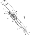
- this invention is directed to an inspection system 10 for a turbine engine in accordance with claim 1. It is adapted for capturing images of components of the turbine engine in-situ, including, but not limited to, a combustor basket 20 and a transition 54.
- the inspection system 10 is formed from an inspection system housing 12 including at least one internal chamber 14 that supports an extendible camera support shaft 16 extending distally through a pilot nozzle port 18 into a combustor 20 of a gas turbine engine 22.
- the inspection system includes a camera 24 capable of capturing high quality images together with position coordinates.
- the inspection system 10 may enable images of internal aspects of the combustor 20 of the gas turbine engine 22 to be captured and recaptured during a subsequent outage so that the images may be analyzed and compared for preventive maintenance, troubleshooting, and the like.
- the inspection system 10 may include three degrees of freedom for the camera 24 mounted on the extendible camera support shaft 16. As such, the inspection system 10 enables the capture of a vast array of images within the combustor 20.
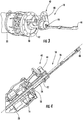
- the inspection system 10 may be formed from one or more inspection system housings 12, as shown in Figures 2 and 5 .
- the inspection system housing 12 may be adapted to be attached to a pilot nozzle port 18, as shown in Figure 3 , after a pilot nozzle and related fuel lines have been removed from the pilot nozzle port 18.
- the inspection system housing 12 may include threads configured to mate with threads on the pilot nozzle port, thereby enabling the inspection system housing 12 to be threadably coupled to the pilot nozzle port 18.
- the inspection system housing 12 may be coupled to the pilot nozzle port 18 via a releasably clamp or other appropriate device.
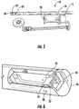
- the inspection system housing 12 includes one or more internal chambers 14, as shown in Figures 2 and 4 , configured to support the extendible camera support shaft 16.
- the internal chamber 14 may have a cross-sectional shape that matches a cross-sectional shape of an outer surface of the extendible camera support shaft 16.
- the internal chamber 14 may have a generally cylindrical shape, and an outer surface of the extendible camera support shaft 16 may be generally cylindrical and sized slightly smaller than the internal chamber 14 such that the extendible camera support shaft 16 fits within the internal chamber 14 without excess movement not aligned with a longitudinal axis 26 of the extendible camera support shaft 16.
- the extendible camera support shaft 16 may be rotatable about the longitudinal axis 26 while the extendible camera support shaft 16 is supported within the internal chamber 14 of the inspection system housing 12.
- the extendible camera support shaft 16 may extend distally from a distal opening 28 in the inspection system housing 12.
- the extendible camera support shaft 16 may be sized to extend from the inspection system housing 12 at the pilot nozzle port 18 through the combustor 20 to a distal end of a transition section 54 extending distally from the combustor 20, as shown in Figure 1 .
- the extendible camera support shaft 16 may be extendible such that a distal end 36 of the extendible camera support shaft 16 is movable longitudinally about the longitudinal axis 26.
- the extendible camera support shaft 16 may be telescopic, thereby enabling the length of the extendible camera support shaft 16 to be changed.
- the extendible camera support shaft 16 may support one or more camera lenses 32 at a location outside of the inspection system housing 12 that is distal to the distal opening 28, as shown in Figure 6 .
- the camera lens 32 may be in communication with the camera 24.
- the camera lens 32 may be attached directly to the camera 24.
- the camera lens 32 may be rotatable about an axis 38 generally orthogonal to the longitudinal axis 26 of the extendible camera support shaft 16, thereby providing adjustable tilt.
- the camera 32 may be rotatable about the axis 38.
- the camera 24 may be, but is not limited to being, a charge-coupled device (CCD) camera capable of capturing high quality images.
- the camera may be, but is not limited to being, a camera 24 with a resolution greater than one megapixel.
- the camera 24 may include a two megapixel sensor that delivers fluid, true-to-life video with the ability of capturing still images up to eight megapixels.
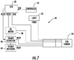
- the inspection system 10, as shown in Figure 7 may include a light 56, such as, but not limited to, a 150 W quartz halogen light to increase visibility in the combustor 20, as shown in Figure 7 .
- the camera lens 32 may be, but is not limited to being, a combined automatic and manual focus lens.
- the extendible camera support shaft 16 may be formed from a tube.
- the extendible camera support shaft 16 may include a camera cavity 34 housing at least a portion of the camera 24.
- the camera 24 may be contained within the camera cavity 34, thereby reducing the risk of damage to the camera 24 or camera lens 32.
- the camera cavity 34 may be positioned at the distal end 36 of the extendible camera support shaft 16.
- the camera cavity 34 may be positioned at a distal end 36 of the extendible camera support shaft 16.
- the inspection system 10 includes a data management system 40, as shown in Figure 7 , configured to coordinate detailed image information together with at least one image captured by the camera 24 in communication with the camera lens 32.
- the data management system 40 may include a central processing unit 50 in communication with the camera 24 and a controller 52.
- the data management system 40 correlates position coordinates with images as metadata.
- the data management system 40 is configured to store images together with position coordinates such that the images may be captured and then recaptured one or more times during subsequent out of service periods. The pictures may then be analyzed to identify changes in the turbine combustor components that may be indicative of a problem.
- the inspection system 10 may capture images of liner holes cracking (below the resonators), plate fin liner outer frame weld cracking, liner thermal barrier coating (TBC) loss or erosion, upper panel exit mouth cracking, lower panel exit mouth cracking, TBC loss or erosion, inlet ring cracking and the like.
- the data management system 40 may also present images together with position coordinates for analysis with algorithms for calculating interval extension of specific components within the turbine engine.
- the inspection system 10, including the camera 24, may be configured to operate within an environment with humidity between about 30% and 95% and an ambient operating temperature of between about 5 degrees Celcius (41 degrees Fahrenheit) and 65 degrees Celcius (150 degrees Fahrenheit).
- the electrical components of the inspection system 10, such as the CPU 50, the camera 24 and associated hardware, may operate on 110 volts at 60 Hertz or on other appropriate power source.
- the inspection system 10 may be automated such that the position of the orientation of the camera 24 and camera lens 32 may be controlled via the data management system 40 in cooperation with one or more motors 42.
- the location, orientation, tilt, and the like of the camera 24 may be established initially by a user, thereby enabling programmable control of three axes of motion.
- the image may be a predetermined image previously input into the data management system 40, which in turn positions the camera 24 according to position coordinates to capture the desired image.
- one or more motors 44 may be in communication with the extendible camera support shaft 16 that is configured to rotate the extendible camera support shaft 16.
- the motor 44 may include a drive shaft in direct contact with the extendible camera support shaft 16 or may be in communication with the extendible camera support shaft 16 through one or more gears, such as, but not limited to, reduction gears.
- one or more motors 46 may be in communication with the at least one extendible camera support shaft 16 that is configured to move the at least one extendible camera support shaft 16 longitudinally along the longitudinal axis 26.
- the motor 46 may include a drive shaft in direct contact with the extendible camera support shaft 16 or may be in communication with the extendible camera support shaft 16 through one or more gears, such as, but not limited to, reduction gears.
- the inspection system 10 may also include one or more motors 48 in communication with the camera lens 32 for rotating the lens 32 about the axis 38 generally orthogonal to the longitudinal axis 26 of the extendible camera support shaft 16. As such, the motor 48 controls tilt of the camera 24.
- the motors 44, 46 and 48 may be formed from any appropriate motor such as, but not limited to, a stepper motor, such as a two-phase - 1/8" step and a DC motor with an encoder.
- the motor 48 may include a drive shaft in direct contact with the camera lens 32 or may be in communication with the camera lens 32 through one or more gears, such as, but not limited to, reduction gears.
- the gas turbine engine 22 is first shutdown and the pilot nozzle and corresponding fuel lines are removed, thereby exposing the pilot nozzle port 18.
- the inspection system housing 12 may be attached to the pilot nozzle port 18 such that the extendible camera support shaft 16 is inserted into the pilot nozzle port 18, and the inspection system housing 12 is attached to the pilot nozzle port 18.
- the camera may then be positioned within the combustor 20 to inspect the operational condition of combustor components on the gas turbine engine 22.
- the linear extension, rotation and tilt of the camera 24 may be controlled manually, or, in another embodiment, may be controlled via one or more motors 42. As such, the motors 42 may control the linear extension, rotation and tilt of the camera 24.
- the data management system 40 may cause the camera 24 to capture an image.
- the data management system 40 also records the position coordinates related to the position of the camera 24 when the image was recorded.
- the data management system 40 may also be used to include notes together with the image. This detailed data information may be recorded by the data management system 40. Once recorded, personnel, such as, but not limited to, inspectors and engineers may review the data and complete a data collection report.
- the data may be used in two ways. For instance, the data may be stored and preserved until the next outage. During the next outage, an image may be recaptured at the same location and then compared with the first image to determine whether a particular indication has gotten worse. Appropriate action may be taken at that point.
- the detailed data information may be used with algorithms to calculate interval extension of specific components within the combustor.
Landscapes
- Engineering & Computer Science (AREA)
- Mechanical Engineering (AREA)
- General Engineering & Computer Science (AREA)
- Chemical & Material Sciences (AREA)
- Combustion & Propulsion (AREA)
- Multimedia (AREA)
- Signal Processing (AREA)
- Investigating Materials By The Use Of Optical Means Adapted For Particular Applications (AREA)
- Testing Of Devices, Machine Parts, Or Other Structures Thereof (AREA)
- Instruments For Viewing The Inside Of Hollow Bodies (AREA)
- Testing Of Engines (AREA)
Applications Claiming Priority (2)
| Application Number | Priority Date | Filing Date | Title |
|---|---|---|---|
| US13/101,338 US8786848B2 (en) | 2011-05-05 | 2011-05-05 | Inspection system for a combustor of a turbine engine |
| PCT/US2012/033893 WO2012151046A2 (en) | 2011-05-05 | 2012-04-17 | Inspection system for a combustor of a turbine engine |
Publications (2)
| Publication Number | Publication Date |
|---|---|
| EP2705304A2 EP2705304A2 (en) | 2014-03-12 |
| EP2705304B1 true EP2705304B1 (en) | 2020-09-16 |
Family
ID=46001849
Family Applications (1)
| Application Number | Title | Priority Date | Filing Date |
|---|---|---|---|
| EP12716986.0A Active EP2705304B1 (en) | 2011-05-05 | 2012-04-17 | Inspection system for a combustor of a turbine engine |
Country Status (7)
Families Citing this family (37)
| Publication number | Priority date | Publication date | Assignee | Title |
|---|---|---|---|---|
| DE102011114541A1 (de) * | 2011-09-30 | 2013-04-04 | Lufthansa Technik Ag | Endoskopiesystem und korrespondierendesVerfahren zur Untersuchung von Gasturbinen |
| US9116071B2 (en) * | 2012-01-31 | 2015-08-25 | Siemens Energy, Inc. | System and method for visual inspection and 3D white light scanning of off-line industrial gas turbines and other power generation machinery |
| US9154743B2 (en) * | 2012-01-31 | 2015-10-06 | Siemens Energy, Inc. | System and method for optical inspection of off-line industrial gas turbines and other power generation machinery while in turning gear mode |
| US8713999B2 (en) * | 2012-01-31 | 2014-05-06 | Siemens Energy, Inc. | System and method for automated optical inspection of industrial gas turbines and other power generation machinery with multi-axis inspection scope |
| US8922640B2 (en) | 2012-01-31 | 2014-12-30 | Siemens Energy, Inc. | System and method for automated optical inspection of industrial gas turbines and other power generation machinery with articulated multi-axis inspection scope |
| US9948835B2 (en) | 2012-01-31 | 2018-04-17 | Siemens Energy, Inc. | Single-axis inspection scope with spherical camera and method for internal inspection of power generation machinery |
| US10281712B2 (en) | 2012-01-31 | 2019-05-07 | Siemens Energy, Inc. | Single-axis inspection scope with bendable knuckle and method for internal inspection of power generation machinery |
| US9778141B2 (en) | 2012-01-31 | 2017-10-03 | Siemens Energy, Inc. | Video inspection system with deformable, self-supporting deployment tether |
| US9057710B2 (en) | 2012-01-31 | 2015-06-16 | Siemens Energy, Inc. | System and method for automated optical inspection of industrial gas turbines and other power generation machinery |
| US10274718B2 (en) | 2012-01-31 | 2019-04-30 | Siemens Energy, Inc. | Single-axis inspection scope with anti-rotation extension and method for internal inspection of power generation machinery |
| US9709463B2 (en) | 2012-01-31 | 2017-07-18 | Siemens Energy, Inc. | Method and system for surface profile inspection of off-line industrial gas turbines and other power generation machinery |
| JP5946733B2 (ja) * | 2012-09-24 | 2016-07-06 | 三菱日立パワーシステムズ株式会社 | 燃焼器の隙間計測装置及び隙間計測方法 |
| US9228941B2 (en) * | 2012-11-07 | 2016-01-05 | Solar Turbines Incorporated | Combustor imaging inspection system |
| US9195044B2 (en) | 2013-08-15 | 2015-11-24 | Siemens Energy, Inc | Optical probe having an inner tube with separable tube sections to house optical elements |
| US9518895B2 (en) | 2013-08-15 | 2016-12-13 | Siemens Energy, Inc. | Optical probe with improved affixing structure for supporting a light-redirecting element |
| US9182285B2 (en) * | 2013-08-15 | 2015-11-10 | Siemens Energy, Inc. | Methods regarding optical probe having an inner tube with separable tube sections to house optical elements |
| US9599537B2 (en) * | 2013-08-21 | 2017-03-21 | Siemens Energy, Inc. | Internal inspection of machinery by stitched surface imaging |
| US9470147B2 (en) | 2013-11-12 | 2016-10-18 | Siemens Energy, Inc. | Apparatus and method for determining a temperature distribution of a hot-temperature flow in a turbine engine |
| US9670795B2 (en) * | 2014-02-26 | 2017-06-06 | Siemens Energy, Inc. | Method for inspecting a turbine engine rotor with a rotor disc cavity inspection apparatus |
| US9681107B2 (en) * | 2014-05-22 | 2017-06-13 | Siemens Energy, Inc. | Flexible tether position tracking camera inspection system for visual inspection of off line industrial gas turbines and other power generation machinery |
| US9618424B2 (en) * | 2014-07-18 | 2017-04-11 | Siemens Energy, Inc. | Gas turbine inspection apparatus and method and system for inspecting a gas turbine |
| US9459153B2 (en) * | 2014-09-17 | 2016-10-04 | General Electric Company | Automated analytics systems and methods |
| US10041371B1 (en) | 2015-02-06 | 2018-08-07 | Siemens Energy, Inc. | In-situ measurement of blade tip-to-shroud gap in turbine engine |
| KR101972853B1 (ko) * | 2015-07-20 | 2019-04-26 | 지멘스 에너지, 인코포레이티드 | 구형 카메라를 갖춘 단축 검사 스코프 및 발전 기계류의 내부 검사 방법 |
| US10119863B2 (en) * | 2016-11-07 | 2018-11-06 | Siemens Energy, Inc. | Flash thermography photobox |
| US11111813B2 (en) * | 2016-12-06 | 2021-09-07 | General Electric Company | Gas turbine engine maintenance method |
| US10533901B2 (en) * | 2017-06-06 | 2020-01-14 | General Electric Company | Imaging system for inspecting components of turbomachines and method of assembly thereof |
| SE541623C2 (en) * | 2017-10-11 | 2019-11-12 | Chris Marine Ab | Liner imaging device and a method for establishing an image of an inner wall of a liner |
| US12194620B2 (en) | 2018-10-15 | 2025-01-14 | Oliver Crisipin Robotics Limited | Selectively flexible extension tool |
| US11702955B2 (en) | 2019-01-14 | 2023-07-18 | General Electric Company | Component repair system and method |
| CN209105309U (zh) * | 2019-01-22 | 2019-07-12 | 京东方科技集团股份有限公司 | 摄像装置及终端设备 |
| US11260477B2 (en) * | 2019-05-02 | 2022-03-01 | MTU Aero Engines AG | Repair tool for turbomachinery and related method |
| US12405187B2 (en) | 2019-10-04 | 2025-09-02 | General Electric Company | Insertion apparatus for use with rotary machines |
| DE102019219273A1 (de) * | 2019-12-10 | 2021-06-10 | MTU Aero Engines AG | Verfahren zum vermessen eines bauteils einer strömungsmaschine |
| US12091981B2 (en) | 2020-06-11 | 2024-09-17 | General Electric Company | Insertion tool and method |
| DE102020135067A1 (de) | 2020-12-29 | 2022-06-30 | Chemin Gmbh | Sondenkopf und Verwendung eines Sondenkopfs |
| CN113514469B (zh) * | 2021-05-28 | 2024-06-04 | 华能苏州热电有限责任公司 | 一种环形燃烧室燃机透平叶片孔窥检查辅助工装及方法 |
Family Cites Families (19)
| Publication number | Priority date | Publication date | Assignee | Title |
|---|---|---|---|---|
| GB2333595B (en) * | 1996-08-16 | 2001-03-21 | David Francis Schaack | Apparatus and method for making accurate three-dimensional size measurements of inaccessible objects |
| US6009189A (en) * | 1996-08-16 | 1999-12-28 | Schaack; David F. | Apparatus and method for making accurate three-dimensional size measurements of inaccessible objects |
| GB9816421D0 (en) * | 1998-07-28 | 1998-09-23 | Keymed Medicals & Ind Equip | Apparatus for delivering laser energy to a remote location |
| US7690840B2 (en) | 1999-12-22 | 2010-04-06 | Siemens Energy, Inc. | Method and apparatus for measuring on-line failure of turbine thermal barrier coatings |
| US6532840B2 (en) * | 2000-12-19 | 2003-03-18 | General Electric Company | Methods for robotically inspecting gas turbine combustion components |
| US6414458B1 (en) * | 2000-12-19 | 2002-07-02 | General Electric Company | Apparatus for robotically inspecting gas turbine combustion components |
| US6380512B1 (en) * | 2001-10-09 | 2002-04-30 | Chromalloy Gas Turbine Corporation | Method for removing coating material from a cooling hole of a gas turbine engine component |
| CA2496935C (en) | 2002-08-28 | 2011-09-13 | Wayne State University | System and method for acoustic chaos in sonic infrared imaging |
| US7121098B2 (en) | 2003-04-30 | 2006-10-17 | Siemens Power Generation, Inc. | High-temperature inspection device and cooling apparatus therefor |
| US7271894B2 (en) | 2003-10-01 | 2007-09-18 | General Electric Company | Imaging system for robotically inspecting gas turbine combustion components |
| US6992315B2 (en) | 2004-03-10 | 2006-01-31 | Siemens Westinghouse Power Corporation | In situ combustion turbine engine airfoil inspection |
| US7294817B2 (en) | 2004-05-06 | 2007-11-13 | Siemens Power Generation, Inc. | System and methods for determining nonuniformity correction parameters in detector-array imaging |
| WO2005121509A1 (en) * | 2004-06-14 | 2005-12-22 | Gas Turbine Efficiency Ab | System and devices for collecting and treating waste water from engine washing |
| US7489811B2 (en) | 2004-10-08 | 2009-02-10 | Siemens Energy, Inc. | Method of visually inspecting turbine blades and optical inspection system therefor |
| US7231817B2 (en) | 2005-01-18 | 2007-06-19 | Siemens Power Generation, Inc. | Inspection system for a turbine blade region of a turbine engine |
| EP1767743A1 (de) * | 2005-09-26 | 2007-03-28 | Siemens Aktiengesellschaft | Verfahren zum Herstellen eines zu beschichtenden Gasturbinen-Bauteils mit freigelegten Öffnungen, Vorrichtung zur Durchführung des Verfahrens und beschichtbare Turbinenschaufel mit Filmkühlöffnungen |
| US7689003B2 (en) | 2006-03-20 | 2010-03-30 | Siemens Energy, Inc. | Combined 2D and 3D nondestructive examination |
| US7887234B2 (en) | 2006-10-20 | 2011-02-15 | Siemens Corporation | Maximum blade surface temperature estimation for advanced stationary gas turbines in near-infrared (with reflection) |
| US7961401B1 (en) * | 2009-12-23 | 2011-06-14 | Ge Inspection Technologies, Lp | System for providing two position zoom-focus |
-
2011
- 2011-05-05 US US13/101,338 patent/US8786848B2/en active Active
-
2012
- 2012-04-17 EP EP12716986.0A patent/EP2705304B1/en active Active
- 2012-04-17 KR KR1020137032218A patent/KR101944962B1/ko active Active
- 2012-04-17 CN CN201280032966.2A patent/CN103649641B/zh active Active
- 2012-04-17 JP JP2014509300A patent/JP2014513766A/ja active Pending
- 2012-04-17 CA CA2834739A patent/CA2834739A1/en not_active Abandoned
- 2012-04-17 WO PCT/US2012/033893 patent/WO2012151046A2/en active Application Filing
Non-Patent Citations (1)
| Title |
|---|
| None * |
Also Published As
| Publication number | Publication date |
|---|---|
| WO2012151046A2 (en) | 2012-11-08 |
| WO2012151046A3 (en) | 2013-11-28 |
| US20120281084A1 (en) | 2012-11-08 |
| CN103649641B (zh) | 2016-06-08 |
| CN103649641A (zh) | 2014-03-19 |
| JP2014513766A (ja) | 2014-06-05 |
| CA2834739A1 (en) | 2012-11-08 |
| KR20140027390A (ko) | 2014-03-06 |
| US8786848B2 (en) | 2014-07-22 |
| KR101944962B1 (ko) | 2019-02-01 |
| EP2705304A2 (en) | 2014-03-12 |
Similar Documents
| Publication | Publication Date | Title |
|---|---|---|
| EP2705304B1 (en) | Inspection system for a combustor of a turbine engine | |
| US11536670B2 (en) | System and method for engine inspection | |
| US9709463B2 (en) | Method and system for surface profile inspection of off-line industrial gas turbines and other power generation machinery | |
| KR101649103B1 (ko) | 오프-라인 산업용 가스 터빈들 및 다른 발전 기계류의 시각적 검사 및 3d 백색광 스캐닝용 시스템 및 방법 | |
| JP6223342B2 (ja) | ガスタービンを検査するための内視鏡検査システムおよび対応する方法 | |
| US9228941B2 (en) | Combustor imaging inspection system | |
| KR102130736B1 (ko) | 가스 터빈 연소기 섹션 내의 온-라인 광학 감시를 위한 시스템 및 방법 | |
| KR102250742B1 (ko) | 플래시 서모그래피 포토박스 | |
| CA3124752A1 (en) | Method and device for inspecting hard-to-reach components | |
| US10262404B2 (en) | Method and system for articulation of a visual inspection device | |
| US20170031492A1 (en) | Control of non-destructive testing devices | |
| US20070251045A1 (en) | System for automatically cleaning and inspecting stud bolt holes, and managing histories of the stud bolt holes | |
| JP2003501577A (ja) | ガスタービンの環状燃焼室の点検装置およびガスタービンの環状燃焼室の点検方法 | |
| US20130197855A1 (en) | Method and apparatus to determine temperature of a gas turbine engine | |
| JP2004354382A (ja) | 流れ開口面積を測定するための方法及び装置 | |
| KR20200019893A (ko) | 원자로 연료 채널 조립체를 위한 검사 도구 및 방법 | |
| KR20230059041A (ko) | 이미지 취득장치를 이용한 설비의 건전성 평가 시스템 및 그 방법 | |
| US20250054229A1 (en) | 3d imaging for engine assembly inspection | |
| CN219104765U (zh) | 一种车内管路检测探头 | |
| WO2019133112A2 (en) | A positioning device and an associated method thereof | |
| WO2024064563A1 (en) | Configurable non-destructive testing device | |
| CN114488512A (zh) | 一种工业内窥镜 | |
| WO2019035807A1 (en) | INTEGRATED IMAGING UNIT FOR HIGH TEMPERATURE AND PRESSURE APPLICATIONS |
Legal Events
| Date | Code | Title | Description |
|---|---|---|---|
| PUAI | Public reference made under article 153(3) epc to a published international application that has entered the european phase |
Free format text: ORIGINAL CODE: 0009012 |
|
| 17P | Request for examination filed |
Effective date: 20131021 |
|
| AK | Designated contracting states |
Kind code of ref document: A2 Designated state(s): AL AT BE BG CH CY CZ DE DK EE ES FI FR GB GR HR HU IE IS IT LI LT LU LV MC MK MT NL NO PL PT RO RS SE SI SK SM TR |
|
| DAX | Request for extension of the european patent (deleted) | ||
| REG | Reference to a national code |
Ref country code: DE Ref legal event code: R079 Ref document number: 602012072346 Country of ref document: DE Free format text: PREVIOUS MAIN CLASS: F23M0011040000 Ipc: F01D0009020000 |
|
| RIC1 | Information provided on ipc code assigned before grant |
Ipc: F01D 21/00 20060101ALI20200408BHEP Ipc: F01D 9/02 20060101AFI20200408BHEP Ipc: H04N 7/18 20060101ALI20200408BHEP |
|
| GRAP | Despatch of communication of intention to grant a patent |
Free format text: ORIGINAL CODE: EPIDOSNIGR1 |
|
| STAA | Information on the status of an ep patent application or granted ep patent |
Free format text: STATUS: GRANT OF PATENT IS INTENDED |
|
| INTG | Intention to grant announced |
Effective date: 20200519 |
|
| GRAS | Grant fee paid |
Free format text: ORIGINAL CODE: EPIDOSNIGR3 |
|
| GRAA | (expected) grant |
Free format text: ORIGINAL CODE: 0009210 |
|
| STAA | Information on the status of an ep patent application or granted ep patent |
Free format text: STATUS: THE PATENT HAS BEEN GRANTED |
|
| AK | Designated contracting states |
Kind code of ref document: B1 Designated state(s): AL AT BE BG CH CY CZ DE DK EE ES FI FR GB GR HR HU IE IS IT LI LT LU LV MC MK MT NL NO PL PT RO RS SE SI SK SM TR |
|
| REG | Reference to a national code |
Ref country code: GB Ref legal event code: FG4D |
|
| REG | Reference to a national code |
Ref country code: CH Ref legal event code: EP |
|
| REG | Reference to a national code |
Ref country code: DE Ref legal event code: R096 Ref document number: 602012072346 Country of ref document: DE |
|
| REG | Reference to a national code |
Ref country code: IE Ref legal event code: FG4D |
|
| REG | Reference to a national code |
Ref country code: AT Ref legal event code: REF Ref document number: 1314334 Country of ref document: AT Kind code of ref document: T Effective date: 20201015 |
|
| PG25 | Lapsed in a contracting state [announced via postgrant information from national office to epo] |
Ref country code: BG Free format text: LAPSE BECAUSE OF FAILURE TO SUBMIT A TRANSLATION OF THE DESCRIPTION OR TO PAY THE FEE WITHIN THE PRESCRIBED TIME-LIMIT Effective date: 20201216 Ref country code: NO Free format text: LAPSE BECAUSE OF FAILURE TO SUBMIT A TRANSLATION OF THE DESCRIPTION OR TO PAY THE FEE WITHIN THE PRESCRIBED TIME-LIMIT Effective date: 20201216 Ref country code: GR Free format text: LAPSE BECAUSE OF FAILURE TO SUBMIT A TRANSLATION OF THE DESCRIPTION OR TO PAY THE FEE WITHIN THE PRESCRIBED TIME-LIMIT Effective date: 20201217 Ref country code: HR Free format text: LAPSE BECAUSE OF FAILURE TO SUBMIT A TRANSLATION OF THE DESCRIPTION OR TO PAY THE FEE WITHIN THE PRESCRIBED TIME-LIMIT Effective date: 20200916 Ref country code: FI Free format text: LAPSE BECAUSE OF FAILURE TO SUBMIT A TRANSLATION OF THE DESCRIPTION OR TO PAY THE FEE WITHIN THE PRESCRIBED TIME-LIMIT Effective date: 20200916 Ref country code: SE Free format text: LAPSE BECAUSE OF FAILURE TO SUBMIT A TRANSLATION OF THE DESCRIPTION OR TO PAY THE FEE WITHIN THE PRESCRIBED TIME-LIMIT Effective date: 20200916 |
|
| REG | Reference to a national code |
Ref country code: AT Ref legal event code: MK05 Ref document number: 1314334 Country of ref document: AT Kind code of ref document: T Effective date: 20200916 |
|
| REG | Reference to a national code |
Ref country code: NL Ref legal event code: MP Effective date: 20200916 |
|
| PG25 | Lapsed in a contracting state [announced via postgrant information from national office to epo] |
Ref country code: RS Free format text: LAPSE BECAUSE OF FAILURE TO SUBMIT A TRANSLATION OF THE DESCRIPTION OR TO PAY THE FEE WITHIN THE PRESCRIBED TIME-LIMIT Effective date: 20200916 Ref country code: LV Free format text: LAPSE BECAUSE OF FAILURE TO SUBMIT A TRANSLATION OF THE DESCRIPTION OR TO PAY THE FEE WITHIN THE PRESCRIBED TIME-LIMIT Effective date: 20200916 |
|
| REG | Reference to a national code |
Ref country code: LT Ref legal event code: MG4D |
|
| PG25 | Lapsed in a contracting state [announced via postgrant information from national office to epo] |
Ref country code: EE Free format text: LAPSE BECAUSE OF FAILURE TO SUBMIT A TRANSLATION OF THE DESCRIPTION OR TO PAY THE FEE WITHIN THE PRESCRIBED TIME-LIMIT Effective date: 20200916 Ref country code: CZ Free format text: LAPSE BECAUSE OF FAILURE TO SUBMIT A TRANSLATION OF THE DESCRIPTION OR TO PAY THE FEE WITHIN THE PRESCRIBED TIME-LIMIT Effective date: 20200916 Ref country code: SM Free format text: LAPSE BECAUSE OF FAILURE TO SUBMIT A TRANSLATION OF THE DESCRIPTION OR TO PAY THE FEE WITHIN THE PRESCRIBED TIME-LIMIT Effective date: 20200916 Ref country code: RO Free format text: LAPSE BECAUSE OF FAILURE TO SUBMIT A TRANSLATION OF THE DESCRIPTION OR TO PAY THE FEE WITHIN THE PRESCRIBED TIME-LIMIT Effective date: 20200916 Ref country code: LT Free format text: LAPSE BECAUSE OF FAILURE TO SUBMIT A TRANSLATION OF THE DESCRIPTION OR TO PAY THE FEE WITHIN THE PRESCRIBED TIME-LIMIT Effective date: 20200916 Ref country code: PT Free format text: LAPSE BECAUSE OF FAILURE TO SUBMIT A TRANSLATION OF THE DESCRIPTION OR TO PAY THE FEE WITHIN THE PRESCRIBED TIME-LIMIT Effective date: 20210118 Ref country code: NL Free format text: LAPSE BECAUSE OF FAILURE TO SUBMIT A TRANSLATION OF THE DESCRIPTION OR TO PAY THE FEE WITHIN THE PRESCRIBED TIME-LIMIT Effective date: 20200916 |
|
| PG25 | Lapsed in a contracting state [announced via postgrant information from national office to epo] |
Ref country code: AL Free format text: LAPSE BECAUSE OF FAILURE TO SUBMIT A TRANSLATION OF THE DESCRIPTION OR TO PAY THE FEE WITHIN THE PRESCRIBED TIME-LIMIT Effective date: 20200916 Ref country code: AT Free format text: LAPSE BECAUSE OF FAILURE TO SUBMIT A TRANSLATION OF THE DESCRIPTION OR TO PAY THE FEE WITHIN THE PRESCRIBED TIME-LIMIT Effective date: 20200916 Ref country code: ES Free format text: LAPSE BECAUSE OF FAILURE TO SUBMIT A TRANSLATION OF THE DESCRIPTION OR TO PAY THE FEE WITHIN THE PRESCRIBED TIME-LIMIT Effective date: 20200916 Ref country code: IS Free format text: LAPSE BECAUSE OF FAILURE TO SUBMIT A TRANSLATION OF THE DESCRIPTION OR TO PAY THE FEE WITHIN THE PRESCRIBED TIME-LIMIT Effective date: 20210116 Ref country code: PL Free format text: LAPSE BECAUSE OF FAILURE TO SUBMIT A TRANSLATION OF THE DESCRIPTION OR TO PAY THE FEE WITHIN THE PRESCRIBED TIME-LIMIT Effective date: 20200916 |
|
| REG | Reference to a national code |
Ref country code: DE Ref legal event code: R097 Ref document number: 602012072346 Country of ref document: DE |
|
| PG25 | Lapsed in a contracting state [announced via postgrant information from national office to epo] |
Ref country code: SK Free format text: LAPSE BECAUSE OF FAILURE TO SUBMIT A TRANSLATION OF THE DESCRIPTION OR TO PAY THE FEE WITHIN THE PRESCRIBED TIME-LIMIT Effective date: 20200916 |
|
| PLBE | No opposition filed within time limit |
Free format text: ORIGINAL CODE: 0009261 |
|
| STAA | Information on the status of an ep patent application or granted ep patent |
Free format text: STATUS: NO OPPOSITION FILED WITHIN TIME LIMIT |
|
| 26N | No opposition filed |
Effective date: 20210617 |
|
| PG25 | Lapsed in a contracting state [announced via postgrant information from national office to epo] |
Ref country code: DK Free format text: LAPSE BECAUSE OF FAILURE TO SUBMIT A TRANSLATION OF THE DESCRIPTION OR TO PAY THE FEE WITHIN THE PRESCRIBED TIME-LIMIT Effective date: 20200916 Ref country code: SI Free format text: LAPSE BECAUSE OF FAILURE TO SUBMIT A TRANSLATION OF THE DESCRIPTION OR TO PAY THE FEE WITHIN THE PRESCRIBED TIME-LIMIT Effective date: 20200916 |
|
| PG25 | Lapsed in a contracting state [announced via postgrant information from national office to epo] |
Ref country code: MC Free format text: LAPSE BECAUSE OF FAILURE TO SUBMIT A TRANSLATION OF THE DESCRIPTION OR TO PAY THE FEE WITHIN THE PRESCRIBED TIME-LIMIT Effective date: 20200916 |
|
| GBPC | Gb: european patent ceased through non-payment of renewal fee |
Effective date: 20210417 |
|
| PG25 | Lapsed in a contracting state [announced via postgrant information from national office to epo] |
Ref country code: LU Free format text: LAPSE BECAUSE OF NON-PAYMENT OF DUE FEES Effective date: 20210417 |
|
| REG | Reference to a national code |
Ref country code: BE Ref legal event code: MM Effective date: 20210430 |
|
| PG25 | Lapsed in a contracting state [announced via postgrant information from national office to epo] |
Ref country code: GB Free format text: LAPSE BECAUSE OF NON-PAYMENT OF DUE FEES Effective date: 20210417 Ref country code: FR Free format text: LAPSE BECAUSE OF NON-PAYMENT OF DUE FEES Effective date: 20210430 Ref country code: LI Free format text: LAPSE BECAUSE OF NON-PAYMENT OF DUE FEES Effective date: 20210430 Ref country code: CH Free format text: LAPSE BECAUSE OF NON-PAYMENT OF DUE FEES Effective date: 20210430 |
|
| PG25 | Lapsed in a contracting state [announced via postgrant information from national office to epo] |
Ref country code: IE Free format text: LAPSE BECAUSE OF NON-PAYMENT OF DUE FEES Effective date: 20210417 |
|
| PG25 | Lapsed in a contracting state [announced via postgrant information from national office to epo] |
Ref country code: IS Free format text: LAPSE BECAUSE OF FAILURE TO SUBMIT A TRANSLATION OF THE DESCRIPTION OR TO PAY THE FEE WITHIN THE PRESCRIBED TIME-LIMIT Effective date: 20210116 |
|
| PG25 | Lapsed in a contracting state [announced via postgrant information from national office to epo] |
Ref country code: BE Free format text: LAPSE BECAUSE OF NON-PAYMENT OF DUE FEES Effective date: 20210430 |
|
| REG | Reference to a national code |
Ref country code: DE Ref legal event code: R082 Ref document number: 602012072346 Country of ref document: DE Representative=s name: ROTH, THOMAS, DIPL.-PHYS. DR., DE |
|
| PG25 | Lapsed in a contracting state [announced via postgrant information from national office to epo] |
Ref country code: HU Free format text: LAPSE BECAUSE OF FAILURE TO SUBMIT A TRANSLATION OF THE DESCRIPTION OR TO PAY THE FEE WITHIN THE PRESCRIBED TIME-LIMIT; INVALID AB INITIO Effective date: 20120417 Ref country code: CY Free format text: LAPSE BECAUSE OF FAILURE TO SUBMIT A TRANSLATION OF THE DESCRIPTION OR TO PAY THE FEE WITHIN THE PRESCRIBED TIME-LIMIT Effective date: 20200916 |
|
| PG25 | Lapsed in a contracting state [announced via postgrant information from national office to epo] |
Ref country code: MK Free format text: LAPSE BECAUSE OF FAILURE TO SUBMIT A TRANSLATION OF THE DESCRIPTION OR TO PAY THE FEE WITHIN THE PRESCRIBED TIME-LIMIT Effective date: 20200916 |
|
| PG25 | Lapsed in a contracting state [announced via postgrant information from national office to epo] |
Ref country code: TR Free format text: LAPSE BECAUSE OF FAILURE TO SUBMIT A TRANSLATION OF THE DESCRIPTION OR TO PAY THE FEE WITHIN THE PRESCRIBED TIME-LIMIT Effective date: 20200916 |
|
| PG25 | Lapsed in a contracting state [announced via postgrant information from national office to epo] |
Ref country code: MT Free format text: LAPSE BECAUSE OF FAILURE TO SUBMIT A TRANSLATION OF THE DESCRIPTION OR TO PAY THE FEE WITHIN THE PRESCRIBED TIME-LIMIT Effective date: 20200916 |
|
| PGFP | Annual fee paid to national office [announced via postgrant information from national office to epo] |
Ref country code: DE Payment date: 20250428 Year of fee payment: 14 |
|
| PGFP | Annual fee paid to national office [announced via postgrant information from national office to epo] |
Ref country code: IT Payment date: 20250422 Year of fee payment: 14 |