EP2704310A1 - Machine électrique et procédé pour le fonctionnement d'une telle machine électrique - Google Patents
Machine électrique et procédé pour le fonctionnement d'une telle machine électrique Download PDFInfo
- Publication number
- EP2704310A1 EP2704310A1 EP12181949.4A EP12181949A EP2704310A1 EP 2704310 A1 EP2704310 A1 EP 2704310A1 EP 12181949 A EP12181949 A EP 12181949A EP 2704310 A1 EP2704310 A1 EP 2704310A1
- Authority
- EP
- European Patent Office
- Prior art keywords
- rotor
- winding
- stator
- electrical machine
- currents
- Prior art date
- Legal status (The legal status is an assumption and is not a legal conclusion. Google has not performed a legal analysis and makes no representation as to the accuracy of the status listed.)
- Granted
Links
Images

Classifications
-
- H—ELECTRICITY
- H02—GENERATION; CONVERSION OR DISTRIBUTION OF ELECTRIC POWER
- H02P—CONTROL OR REGULATION OF ELECTRIC MOTORS, ELECTRIC GENERATORS OR DYNAMO-ELECTRIC CONVERTERS; CONTROLLING TRANSFORMERS, REACTORS OR CHOKE COILS
- H02P9/00—Arrangements for controlling electric generators for the purpose of obtaining a desired output
- H02P9/08—Control of generator circuit during starting or stopping of driving means, e.g. for initiating excitation
-
- H—ELECTRICITY
- H02—GENERATION; CONVERSION OR DISTRIBUTION OF ELECTRIC POWER
- H02P—CONTROL OR REGULATION OF ELECTRIC MOTORS, ELECTRIC GENERATORS OR DYNAMO-ELECTRIC CONVERTERS; CONTROLLING TRANSFORMERS, REACTORS OR CHOKE COILS
- H02P9/00—Arrangements for controlling electric generators for the purpose of obtaining a desired output
- H02P9/10—Control effected upon generator excitation circuit to reduce harmful effects of overloads or transients, e.g. sudden application of load, sudden removal of load, sudden change of load
Definitions
- the present disclosure relates to an electrical machine and a method for operating such an electrical machine.
- the electrical machine is a rotating electrical machine such as a synchronous generator to be connected to a gas or steam turbine (turbogenerator) or a synchronous generator to be connected to a hydro turbine (hydro generator) or an asynchronous generator or a synchronous or asynchronous electric motor or also other types of electric machines.
- a rotating electrical machine such as a synchronous generator to be connected to a gas or steam turbine (turbogenerator) or a synchronous generator to be connected to a hydro turbine (hydro generator) or an asynchronous generator or a synchronous or asynchronous electric motor or also other types of electric machines.
- Electrical machines such as electrical generators (typically electrical generators are synchronous machines, in the following it is referred to as main electrical machine) have a rotor with a rotor winding that is supplied with electric power, and a stator with a stator winding to collect electric power to be supplied to a supply network.
- a first excitation system is the so called static excitation system; it includes a static rectifier connected at one side to the supply network to receive AC electric power, and at the other side to slip rings, to transfer DC electric power to the rotor windings.
- a disadvantage of the static excitation systems is that during operation, the slip rings and brushes connected thereto undergo wear that cause carbon dust generation.
- the brushless excitation systems include an excitation rotor, with a three-phase or multi-phase excitation rotor winding and an excitation stator having a DC excitation stator winding.
- EP 1 289 118 A1 discloses a brushless excitation system; in particular, it discloses an excitation system with an AC excitation rotor winding connected to a rotating rectifier (that is in turn connected to the rotor of the main electrical machine) and an excitation stator with a DC excitation stator winding.
- the electrical machine comprises a first rotor with a first rotor winding and a first stator with a first stator winding, and an excitation device for supplying current to the first rotor winding.
- the excitation device has a second rotor with a second rotor winding, the second rotor being connected to the first rotor in a fixed rotational relationship, and a second stator with a second stator winding.
- the electrical machine is characterized in that the second rotor winding and the second stator winding are multi-phase windings, and the first and second rotor windings are connected to one another.
- phase-connecting conductors In a first refinement all phases of the first and second rotor windings are connected to one another by phase-connecting conductors.
- first and second rotor windings are arranged on a common rotor shaft.
- phase-connecting conductors run within the rotor shaft.
- the excitation device defines an asynchronous electrical machine.
- the first rotor winding is a multi-phase winding, and the first and second rotor windings are connected directly to one another (i.e. without other components such as rectifiers interposed).
- the rotor currents through the first rotor winding are determined based on the stator currents through the second stator winding of the excitation device.
- the speed of the rotor is measured and the rotor currents through the first rotor winding are determined from the measured speed and an equivalent circuit diagram of the excitation device.
- a machine model of the excitation device is used to determine the rotor currents through the first rotor winding, such that the rotor currents through the first rotor winding are computed based on the measured currents of the excitation device.
- the determination of the rotor currents through the first rotor winding is carried out by means of a multi-stage cascade control, wherein the magnetization and the torque of the machine are controlled by means of the stator currents through the first stator winding, which for their part are controlled by the rotor currents through the first rotor winding, which in turn are themselves controlled by impressing the stator-side currents through the second stator winding of the excitation device.
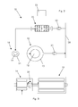
- the main electrical machine 10 is for example an asynchronous electrical machine such as an electrical generator of a variable-speed energy production in pumped storage plants and/or windmills.
- the main electrical machine 10 comprises a rotor 12 having a rotor shaft 12a which rotates about a machine axis 11.
- the rotor 12 has a first rotor core 13 (that can be a laminated or non laminated) with an associated first rotor winding 14.
- the rotor core 13 is concentrically encompassed by a stator 15 having a first stator laminated core 16 with a first stator winding 17; the stator winding 17 is connected to a supply network 28.
- This main electrical machine 10 is associated to an excitation device 18 that supplies the first rotor winding 14 with current.
- the excitation device 18 comprises a second rotor core 19 (laminated or non laminated core) having an associated second rotor winding 20 which is concentrically encompassed by a second stator laminated core 21 that has a second stator winding 22.
- the second rotor core 19 is connected to the first rotor core 13 in a fixed rotational relationship, for example the second rotor core 19 is arranged on the rotor shaft 12a (other solutions are anyhow possible).
- the first and second rotor winding 14 and 20 are multi-phase windings and are directly connected to one another by means of phase-connecting conductors 29.
- the two windings 14, 20 are three-phase windings which can consist of one or more parallel circuits.
- the main electrical machine is an asynchronous electrical machine
- no diodes for rectification are required between the windings 14 and 20.
- phase-connecting conductors 29 is advantageously laid in the rotor shaft 12a (see the arrows in Fig. 1 ). This solution is distinguished by the inherent safety (with regard to overvoltages) and the relative simplicity on the rotating part of the machine.
- the control on the main electrical machine is carried out by controlling the current induced into the second rotor core 19 of the excitation device 18.
- the excitation device 18 can be looked upon as a rotating transformer, wherein the transformation ratio is dependent on speed.
- the current supplied to the second stator winding 22 must be controlled to obtain the required current at the second rotor winding 20.
- the rotor currents can be determined by calculation starting from the stator currents through the stator winding 22 of the excitation device 18.
- this can be done with a multi-stage cascade control.
- a controller/regulator 23 which receives information relating to the stator currents in the stator winding 17 via a current sensor 26, is provided for this purpose. Furthermore, the controller/regulator 23 receives the present speed of the machine from a rotational speed sensor 27 arranged on the rotor shaft 12a; alternatively any or all of this information (but preferably the stator currents in the stator winding 17) can be derived from a machine model.
- the power supply 25 (e.g. a converter) of the stator winding 22 of the excitation device 18 is controlled by the controller/regulator 23.
- the quality of the control of the rotor currents can be improved by the use of a mathematical machine model 24 (observer), as a measurement of these currents is not provided.
- a machine model 24 provides the controller/regulator 23 with the necessary relationships for determining the rotor currents in the rotor winding 14 of the main machine.
- the operation of the electrical machine is substantially the following.
- Figure 2 shows an example of a main electrical machine 10 connected to a supply network 28.
- the supply network 28 is connected via a transformer 30 to the power supply 25 that is connected to the power regulator 23.
- the power supply 25 is in turn connected to the second winding 22 of the second stator core 21 that can induce current into the second winding 20 of the second rotor core 19.
- the second winding 20 is connected to the first winding 14 of the first rotor core 13 that in turn induces electric power into the first winding 17 of the first stator core 16.
- the first winding 17 is connected to the supply network 28 via a transformer 31.
- the second winding 22 is supplied with the current Is that is determined on the basis of the desired current Ir at the second winding 20 (Ir is the same current that is supplied to the first winding 14) and second rotor core speed.
- the current Is is an AC current such as a three-phase current; it is clear that any number of phases for the current is possible.
- the current Is induces the current Ir into the rotor winding 19.
- the current Ir is transmitted to the first rotor winding 14 via the phase-connecting conductors 29. From the first rotor winding 14 the current Ir induces electric power into the first stator winding 17.
- the current Is is changed accordingly to obtain the desired Ir; this can be done at start up, stop or during regulation of for example a wind or hydro turbine.
- the rotor can also be provided with a rotating rectifier 33 in case at the first rotor core 13 DC electric power is needed (for example if the main electrical machine defines an synchronous machine).
- the excitation device of the present disclosure can be used together with first rotor and stator that define an asynchronous machine, a synchronous machine or doubly-fed asynchronous machines (such as those used for the variable-speed production of energy in pumped storage plants and are also used in windmills).
- the excitation device of the disclosure can be used with fast rotating synchronous machines (turbo generators, hydro generators with a low number of poles, and similar machines) and low-speed machines (in this case the excitation device serves to transmit the power from the stator to the rotor only by non-contact means and can therefore be built correspondingly smaller).
- the excitation device is also suitable for exciting the synchronous machine at standstill, which is not possible with conventional brushless excitation devices. This is important particularly when starting synchronous machines in motor mode.
Priority Applications (5)
| Application Number | Priority Date | Filing Date | Title |
|---|---|---|---|
| EP12181949.4A EP2704310B1 (fr) | 2012-08-28 | 2012-08-28 | Procédé pour le fonctionnement d'une telle machine électrique |
| CA2824171A CA2824171C (fr) | 2012-08-28 | 2013-08-20 | Machine electrique et methode de fonctionnement d'une telle machine |
| RU2013139161/07A RU2562811C2 (ru) | 2012-08-28 | 2013-08-22 | Электрическая машина и способ приведения в действие такой электрической машины |
| CN201310469476.5A CN103701260A (zh) | 2012-08-28 | 2013-08-28 | 电机和用于运行这种电机的方法 |
| JP2013176824A JP2014045649A (ja) | 2012-08-28 | 2013-08-28 | 電気機械、および、電気機械の動作方法 |
Applications Claiming Priority (1)
| Application Number | Priority Date | Filing Date | Title |
|---|---|---|---|
| EP12181949.4A EP2704310B1 (fr) | 2012-08-28 | 2012-08-28 | Procédé pour le fonctionnement d'une telle machine électrique |
Publications (2)
| Publication Number | Publication Date |
|---|---|
| EP2704310A1 true EP2704310A1 (fr) | 2014-03-05 |
| EP2704310B1 EP2704310B1 (fr) | 2019-02-13 |
Family
ID=46969997
Family Applications (1)
| Application Number | Title | Priority Date | Filing Date |
|---|---|---|---|
| EP12181949.4A Not-in-force EP2704310B1 (fr) | 2012-08-28 | 2012-08-28 | Procédé pour le fonctionnement d'une telle machine électrique |
Country Status (5)
| Country | Link |
|---|---|
| EP (1) | EP2704310B1 (fr) |
| JP (1) | JP2014045649A (fr) |
| CN (1) | CN103701260A (fr) |
| CA (1) | CA2824171C (fr) |
| RU (1) | RU2562811C2 (fr) |
Cited By (1)
| Publication number | Priority date | Publication date | Assignee | Title |
|---|---|---|---|---|
| DE102020004954A1 (de) | 2020-08-14 | 2022-02-17 | Erich Gintenreiter | Modifizierter Synchrongenerator / Motor Satz der durch gesteuerten / geregelten Polradwinkel = änderung als Generator Wirkleistung abgibt und als Motor die Drehzahl ändert |
Families Citing this family (1)
| Publication number | Priority date | Publication date | Assignee | Title |
|---|---|---|---|---|
| FR3076407B1 (fr) * | 2018-01-02 | 2020-06-19 | Valeo Systemes D'essuyage | Rotor de machine electrique tournante et procede de fabrication associe |
Citations (2)
| Publication number | Priority date | Publication date | Assignee | Title |
|---|---|---|---|---|
| EP1289118A1 (fr) | 2001-08-24 | 2003-03-05 | Siemens Aktiengesellschaft | Méthode et dispositif pour démarrer un turbogénérateur |
| US20070194572A1 (en) * | 2006-02-22 | 2007-08-23 | Honeywell International, Inc. | Brushless starter-generator with independently controllable exciter field |
Family Cites Families (12)
| Publication number | Priority date | Publication date | Assignee | Title |
|---|---|---|---|---|
| JPS50109409A (fr) * | 1974-02-08 | 1975-08-28 | ||
| JPS6126455A (ja) * | 1984-07-17 | 1986-02-05 | Mitsui Eng & Shipbuild Co Ltd | 電動機 |
| JP3403461B2 (ja) * | 1993-06-29 | 2003-05-06 | 東芝エンジニアリング株式会社 | ブラシレス交流励磁回転電機 |
| CA2518953A1 (fr) * | 2003-03-14 | 2004-09-23 | Abb Research Ltd | Methode d'estimation servant a reguler une machine synchrone excitee sans balai |
| JP4591075B2 (ja) * | 2004-12-24 | 2010-12-01 | 株式会社日立製作所 | タービン発電機 |
| JP5019149B2 (ja) * | 2005-06-30 | 2012-09-05 | 西芝電機株式会社 | 軸駆動発電機 |
| JP2007053889A (ja) * | 2005-07-21 | 2007-03-01 | Fumihiko Saito | 発電機 |
| JP2007143301A (ja) * | 2005-11-18 | 2007-06-07 | Nishishiba Electric Co Ltd | 回転電機 |
| RU2331792C2 (ru) * | 2006-09-19 | 2008-08-20 | Анатолий Михайлович Русаков | Магнитоэлектрический обращенный ветрогенератор |
| EP2262101A1 (fr) * | 2009-06-12 | 2010-12-15 | Siemens Aktiengesellschaft | Procédé et agencement destinés à la rotation d'un ensemble turbo |
| CN202282713U (zh) * | 2011-10-31 | 2012-06-20 | 王光顺 | 直接并网变速恒频发电机 |
| CN102601473B (zh) * | 2012-01-13 | 2013-06-19 | 哈尔滨工业大学 | 基于磁悬浮伺服驱动的微小孔电火花加工的主轴装置 |
-
2012
- 2012-08-28 EP EP12181949.4A patent/EP2704310B1/fr not_active Not-in-force
-
2013
- 2013-08-20 CA CA2824171A patent/CA2824171C/fr not_active Expired - Fee Related
- 2013-08-22 RU RU2013139161/07A patent/RU2562811C2/ru not_active IP Right Cessation
- 2013-08-28 CN CN201310469476.5A patent/CN103701260A/zh active Pending
- 2013-08-28 JP JP2013176824A patent/JP2014045649A/ja active Pending
Patent Citations (2)
| Publication number | Priority date | Publication date | Assignee | Title |
|---|---|---|---|---|
| EP1289118A1 (fr) | 2001-08-24 | 2003-03-05 | Siemens Aktiengesellschaft | Méthode et dispositif pour démarrer un turbogénérateur |
| US20070194572A1 (en) * | 2006-02-22 | 2007-08-23 | Honeywell International, Inc. | Brushless starter-generator with independently controllable exciter field |
Non-Patent Citations (1)
| Title |
|---|
| DELALOYE C ET AL: "Estimation of Field Current in Vector-Controlled Synchronous Machine Variable-Speed Drives Employing Brushless Asynchronous Exciters", IEEE TRANSACTIONS ON INDUSTRY APPLICATIONS, IEEE SERVICE CENTER, PISCATAWAY, NJ, US, vol. 41, no. 3, 1 May 2005 (2005-05-01), pages 834 - 840, XP011132528, ISSN: 0093-9994, DOI: 10.1109/TIA.2005.847290 * |
Cited By (1)
| Publication number | Priority date | Publication date | Assignee | Title |
|---|---|---|---|---|
| DE102020004954A1 (de) | 2020-08-14 | 2022-02-17 | Erich Gintenreiter | Modifizierter Synchrongenerator / Motor Satz der durch gesteuerten / geregelten Polradwinkel = änderung als Generator Wirkleistung abgibt und als Motor die Drehzahl ändert |
Also Published As
| Publication number | Publication date |
|---|---|
| JP2014045649A (ja) | 2014-03-13 |
| CN103701260A (zh) | 2014-04-02 |
| RU2013139161A (ru) | 2015-02-27 |
| CA2824171A1 (fr) | 2014-02-28 |
| EP2704310B1 (fr) | 2019-02-13 |
| RU2562811C2 (ru) | 2015-09-10 |
| CA2824171C (fr) | 2017-11-07 |
Similar Documents
| Publication | Publication Date | Title |
|---|---|---|
| US7554302B2 (en) | Slip-controlled, wound-rotor induction machine for wind turbine and other applications | |
| JP2019149936A (ja) | 可変状況で作動するアセンブリ | |
| US8754615B2 (en) | Conversion of synchronous generator to synchronous condenser | |
| CN102195427B (zh) | 一种两级式混合励磁无刷同步电机 | |
| EP2161821B1 (fr) | Générateur à commande magnétique | |
| US10491146B2 (en) | System and method for compensating for generator-induced flicker in a wind turbine | |
| Beik et al. | High-voltage hybrid generator and conversion system for wind turbine applications | |
| CN102386828B (zh) | 操作风力涡轮及确定永磁体温度的方法和涡轮的控制器 | |
| US10075106B2 (en) | DC synchronous machine | |
| CN103460585B (zh) | 航空器的电能源 | |
| US20130101397A1 (en) | Electrical power supply for equipment carried by a rotary support | |
| CN109450202A (zh) | 双12脉波双流无刷发电机 | |
| US20100207479A1 (en) | Electric generator | |
| EP2704310B1 (fr) | Procédé pour le fonctionnement d'une telle machine électrique | |
| CN101350527A (zh) | 变速驱动系统 | |
| KR101417509B1 (ko) | 이중 회전자를 갖는 동기 발전기 시스템 | |
| JP2022552104A (ja) | ガスタービン発電機における低速を検出するシステム及び方法 | |
| Htay et al. | Design and construction of automatic voltage regulator for diesel engine type stand-alone synchronous generator | |
| JP2021191176A (ja) | 同期発電機の励磁制御装置 | |
| Hedayati et al. | Circulating power test setup for a PWM rectifier motor drive | |
| Babu et al. | Shaft torque estimation method for in-service underloaded Induction Motors | |
| JPWO2012093492A1 (ja) | 回転機の試験設備 | |
| JP5858222B2 (ja) | 排熱回収装置 | |
| CN113013918A (zh) | 并网型直流励磁同步发电机组的交流励磁改造方法及系统 | |
| KR101380023B1 (ko) | 초전도 발전기 시스템 |
Legal Events
| Date | Code | Title | Description |
|---|---|---|---|
| AK | Designated contracting states |
Kind code of ref document: A1 Designated state(s): AL AT BE BG CH CY CZ DE DK EE ES FI FR GB GR HR HU IE IS IT LI LT LU LV MC MK MT NL NO PL PT RO RS SE SI SK SM TR |
|
| AX | Request for extension of the european patent |
Extension state: BA ME |
|
| PUAI | Public reference made under article 153(3) epc to a published international application that has entered the european phase |
Free format text: ORIGINAL CODE: 0009012 |
|
| 17P | Request for examination filed |
Effective date: 20140220 |
|
| RBV | Designated contracting states (corrected) |
Designated state(s): AL AT BE BG CH CY CZ DE DK EE ES FI FR GB GR HR HU IE IS IT LI LT LU LV MC MK MT NL NO PL PT RO RS SE SI SK SM TR |
|
| RAP1 | Party data changed (applicant data changed or rights of an application transferred) |
Owner name: GE RENEWABLE TECHNOLOGIES |
|
| STAA | Information on the status of an ep patent application or granted ep patent |
Free format text: STATUS: EXAMINATION IS IN PROGRESS |
|
| 17Q | First examination report despatched |
Effective date: 20170710 |
|
| GRAP | Despatch of communication of intention to grant a patent |
Free format text: ORIGINAL CODE: EPIDOSNIGR1 |
|
| STAA | Information on the status of an ep patent application or granted ep patent |
Free format text: STATUS: GRANT OF PATENT IS INTENDED |
|
| INTG | Intention to grant announced |
Effective date: 20180827 |
|
| GRAS | Grant fee paid |
Free format text: ORIGINAL CODE: EPIDOSNIGR3 |
|
| GRAA | (expected) grant |
Free format text: ORIGINAL CODE: 0009210 |
|
| STAA | Information on the status of an ep patent application or granted ep patent |
Free format text: STATUS: THE PATENT HAS BEEN GRANTED |
|
| AK | Designated contracting states |
Kind code of ref document: B1 Designated state(s): AL AT BE BG CH CY CZ DE DK EE ES FI FR GB GR HR HU IE IS IT LI LT LU LV MC MK MT NL NO PL PT RO RS SE SI SK SM TR |
|
| REG | Reference to a national code |
Ref country code: GB Ref legal event code: FG4D |
|
| REG | Reference to a national code |
Ref country code: CH Ref legal event code: EP Ref country code: AT Ref legal event code: REF Ref document number: 1096794 Country of ref document: AT Kind code of ref document: T Effective date: 20190215 |
|
| REG | Reference to a national code |
Ref country code: CH Ref legal event code: NV Representative=s name: VALIPAT S.A. GEVERS SA, CH |
|
| REG | Reference to a national code |
Ref country code: IE Ref legal event code: FG4D |
|
| REG | Reference to a national code |
Ref country code: DE Ref legal event code: R096 Ref document number: 602012056600 Country of ref document: DE |
|
| REG | Reference to a national code |
Ref country code: CH Ref legal event code: PCAR Free format text: NEW ADDRESS: RUE DES NOYERS 11, 2000 NEUCHATEL (CH) |
|
| REG | Reference to a national code |
Ref country code: LT Ref legal event code: MG4D |
|
| REG | Reference to a national code |
Ref country code: NL Ref legal event code: MP Effective date: 20190213 |
|
| PG25 | Lapsed in a contracting state [announced via postgrant information from national office to epo] |
Ref country code: FI Free format text: LAPSE BECAUSE OF FAILURE TO SUBMIT A TRANSLATION OF THE DESCRIPTION OR TO PAY THE FEE WITHIN THE PRESCRIBED TIME-LIMIT Effective date: 20190213 Ref country code: LT Free format text: LAPSE BECAUSE OF FAILURE TO SUBMIT A TRANSLATION OF THE DESCRIPTION OR TO PAY THE FEE WITHIN THE PRESCRIBED TIME-LIMIT Effective date: 20190213 Ref country code: NL Free format text: LAPSE BECAUSE OF FAILURE TO SUBMIT A TRANSLATION OF THE DESCRIPTION OR TO PAY THE FEE WITHIN THE PRESCRIBED TIME-LIMIT Effective date: 20190213 Ref country code: SE Free format text: LAPSE BECAUSE OF FAILURE TO SUBMIT A TRANSLATION OF THE DESCRIPTION OR TO PAY THE FEE WITHIN THE PRESCRIBED TIME-LIMIT Effective date: 20190213 Ref country code: NO Free format text: LAPSE BECAUSE OF FAILURE TO SUBMIT A TRANSLATION OF THE DESCRIPTION OR TO PAY THE FEE WITHIN THE PRESCRIBED TIME-LIMIT Effective date: 20190513 Ref country code: PT Free format text: LAPSE BECAUSE OF FAILURE TO SUBMIT A TRANSLATION OF THE DESCRIPTION OR TO PAY THE FEE WITHIN THE PRESCRIBED TIME-LIMIT Effective date: 20190613 |
|
| PG25 | Lapsed in a contracting state [announced via postgrant information from national office to epo] |
Ref country code: IS Free format text: LAPSE BECAUSE OF FAILURE TO SUBMIT A TRANSLATION OF THE DESCRIPTION OR TO PAY THE FEE WITHIN THE PRESCRIBED TIME-LIMIT Effective date: 20190613 Ref country code: HR Free format text: LAPSE BECAUSE OF FAILURE TO SUBMIT A TRANSLATION OF THE DESCRIPTION OR TO PAY THE FEE WITHIN THE PRESCRIBED TIME-LIMIT Effective date: 20190213 Ref country code: LV Free format text: LAPSE BECAUSE OF FAILURE TO SUBMIT A TRANSLATION OF THE DESCRIPTION OR TO PAY THE FEE WITHIN THE PRESCRIBED TIME-LIMIT Effective date: 20190213 Ref country code: GR Free format text: LAPSE BECAUSE OF FAILURE TO SUBMIT A TRANSLATION OF THE DESCRIPTION OR TO PAY THE FEE WITHIN THE PRESCRIBED TIME-LIMIT Effective date: 20190514 Ref country code: RS Free format text: LAPSE BECAUSE OF FAILURE TO SUBMIT A TRANSLATION OF THE DESCRIPTION OR TO PAY THE FEE WITHIN THE PRESCRIBED TIME-LIMIT Effective date: 20190213 Ref country code: BG Free format text: LAPSE BECAUSE OF FAILURE TO SUBMIT A TRANSLATION OF THE DESCRIPTION OR TO PAY THE FEE WITHIN THE PRESCRIBED TIME-LIMIT Effective date: 20190513 |
|
| PG25 | Lapsed in a contracting state [announced via postgrant information from national office to epo] |
Ref country code: AL Free format text: LAPSE BECAUSE OF FAILURE TO SUBMIT A TRANSLATION OF THE DESCRIPTION OR TO PAY THE FEE WITHIN THE PRESCRIBED TIME-LIMIT Effective date: 20190213 Ref country code: CZ Free format text: LAPSE BECAUSE OF FAILURE TO SUBMIT A TRANSLATION OF THE DESCRIPTION OR TO PAY THE FEE WITHIN THE PRESCRIBED TIME-LIMIT Effective date: 20190213 Ref country code: ES Free format text: LAPSE BECAUSE OF FAILURE TO SUBMIT A TRANSLATION OF THE DESCRIPTION OR TO PAY THE FEE WITHIN THE PRESCRIBED TIME-LIMIT Effective date: 20190213 Ref country code: SK Free format text: LAPSE BECAUSE OF FAILURE TO SUBMIT A TRANSLATION OF THE DESCRIPTION OR TO PAY THE FEE WITHIN THE PRESCRIBED TIME-LIMIT Effective date: 20190213 Ref country code: IT Free format text: LAPSE BECAUSE OF FAILURE TO SUBMIT A TRANSLATION OF THE DESCRIPTION OR TO PAY THE FEE WITHIN THE PRESCRIBED TIME-LIMIT Effective date: 20190213 Ref country code: RO Free format text: LAPSE BECAUSE OF FAILURE TO SUBMIT A TRANSLATION OF THE DESCRIPTION OR TO PAY THE FEE WITHIN THE PRESCRIBED TIME-LIMIT Effective date: 20190213 Ref country code: EE Free format text: LAPSE BECAUSE OF FAILURE TO SUBMIT A TRANSLATION OF THE DESCRIPTION OR TO PAY THE FEE WITHIN THE PRESCRIBED TIME-LIMIT Effective date: 20190213 Ref country code: DK Free format text: LAPSE BECAUSE OF FAILURE TO SUBMIT A TRANSLATION OF THE DESCRIPTION OR TO PAY THE FEE WITHIN THE PRESCRIBED TIME-LIMIT Effective date: 20190213 |
|
| REG | Reference to a national code |
Ref country code: DE Ref legal event code: R097 Ref document number: 602012056600 Country of ref document: DE |
|
| PG25 | Lapsed in a contracting state [announced via postgrant information from national office to epo] |
Ref country code: PL Free format text: LAPSE BECAUSE OF FAILURE TO SUBMIT A TRANSLATION OF THE DESCRIPTION OR TO PAY THE FEE WITHIN THE PRESCRIBED TIME-LIMIT Effective date: 20190213 Ref country code: SM Free format text: LAPSE BECAUSE OF FAILURE TO SUBMIT A TRANSLATION OF THE DESCRIPTION OR TO PAY THE FEE WITHIN THE PRESCRIBED TIME-LIMIT Effective date: 20190213 |
|
| PLBE | No opposition filed within time limit |
Free format text: ORIGINAL CODE: 0009261 |
|
| STAA | Information on the status of an ep patent application or granted ep patent |
Free format text: STATUS: NO OPPOSITION FILED WITHIN TIME LIMIT |
|
| 26N | No opposition filed |
Effective date: 20191114 |
|
| PG25 | Lapsed in a contracting state [announced via postgrant information from national office to epo] |
Ref country code: SI Free format text: LAPSE BECAUSE OF FAILURE TO SUBMIT A TRANSLATION OF THE DESCRIPTION OR TO PAY THE FEE WITHIN THE PRESCRIBED TIME-LIMIT Effective date: 20190213 |
|
| REG | Reference to a national code |
Ref country code: DE Ref legal event code: R119 Ref document number: 602012056600 Country of ref document: DE |
|
| PG25 | Lapsed in a contracting state [announced via postgrant information from national office to epo] |
Ref country code: TR Free format text: LAPSE BECAUSE OF FAILURE TO SUBMIT A TRANSLATION OF THE DESCRIPTION OR TO PAY THE FEE WITHIN THE PRESCRIBED TIME-LIMIT Effective date: 20190213 |
|
| GBPC | Gb: european patent ceased through non-payment of renewal fee |
Effective date: 20190828 |
|
| PG25 | Lapsed in a contracting state [announced via postgrant information from national office to epo] |
Ref country code: MC Free format text: LAPSE BECAUSE OF FAILURE TO SUBMIT A TRANSLATION OF THE DESCRIPTION OR TO PAY THE FEE WITHIN THE PRESCRIBED TIME-LIMIT Effective date: 20190213 Ref country code: CH Free format text: LAPSE BECAUSE OF NON-PAYMENT OF DUE FEES Effective date: 20190831 Ref country code: LU Free format text: LAPSE BECAUSE OF NON-PAYMENT OF DUE FEES Effective date: 20190828 Ref country code: LI Free format text: LAPSE BECAUSE OF NON-PAYMENT OF DUE FEES Effective date: 20190831 |
|
| REG | Reference to a national code |
Ref country code: BE Ref legal event code: MM Effective date: 20190831 |
|
| PG25 | Lapsed in a contracting state [announced via postgrant information from national office to epo] |
Ref country code: DE Free format text: LAPSE BECAUSE OF NON-PAYMENT OF DUE FEES Effective date: 20200303 Ref country code: FR Free format text: LAPSE BECAUSE OF NON-PAYMENT OF DUE FEES Effective date: 20190831 Ref country code: IE Free format text: LAPSE BECAUSE OF NON-PAYMENT OF DUE FEES Effective date: 20190828 |
|
| PG25 | Lapsed in a contracting state [announced via postgrant information from national office to epo] |
Ref country code: BE Free format text: LAPSE BECAUSE OF NON-PAYMENT OF DUE FEES Effective date: 20190831 Ref country code: GB Free format text: LAPSE BECAUSE OF NON-PAYMENT OF DUE FEES Effective date: 20190828 |
|
| REG | Reference to a national code |
Ref country code: AT Ref legal event code: MM01 Ref document number: 1096794 Country of ref document: AT Kind code of ref document: T Effective date: 20190828 |
|
| PG25 | Lapsed in a contracting state [announced via postgrant information from national office to epo] |
Ref country code: AT Free format text: LAPSE BECAUSE OF NON-PAYMENT OF DUE FEES Effective date: 20190828 |
|
| PG25 | Lapsed in a contracting state [announced via postgrant information from national office to epo] |
Ref country code: CY Free format text: LAPSE BECAUSE OF FAILURE TO SUBMIT A TRANSLATION OF THE DESCRIPTION OR TO PAY THE FEE WITHIN THE PRESCRIBED TIME-LIMIT Effective date: 20190213 |
|
| PG25 | Lapsed in a contracting state [announced via postgrant information from national office to epo] |
Ref country code: MT Free format text: LAPSE BECAUSE OF FAILURE TO SUBMIT A TRANSLATION OF THE DESCRIPTION OR TO PAY THE FEE WITHIN THE PRESCRIBED TIME-LIMIT Effective date: 20190213 Ref country code: HU Free format text: LAPSE BECAUSE OF FAILURE TO SUBMIT A TRANSLATION OF THE DESCRIPTION OR TO PAY THE FEE WITHIN THE PRESCRIBED TIME-LIMIT; INVALID AB INITIO Effective date: 20120828 |
|
| PG25 | Lapsed in a contracting state [announced via postgrant information from national office to epo] |
Ref country code: MK Free format text: LAPSE BECAUSE OF FAILURE TO SUBMIT A TRANSLATION OF THE DESCRIPTION OR TO PAY THE FEE WITHIN THE PRESCRIBED TIME-LIMIT Effective date: 20190213 |
|
| REG | Reference to a national code |
Ref country code: AT Ref legal event code: UEP Ref document number: 1096794 Country of ref document: AT Kind code of ref document: T Effective date: 20190213 |