EP2704292B1 - Feed apparatus, current collector, and power transfer apparatus of the magnetic induction type, considering lateral deviation - Google Patents
Feed apparatus, current collector, and power transfer apparatus of the magnetic induction type, considering lateral deviation Download PDFInfo
- Publication number
- EP2704292B1 EP2704292B1 EP12777602.9A EP12777602A EP2704292B1 EP 2704292 B1 EP2704292 B1 EP 2704292B1 EP 12777602 A EP12777602 A EP 12777602A EP 2704292 B1 EP2704292 B1 EP 2704292B1
- Authority
- EP
- European Patent Office
- Prior art keywords
- feed
- collecting
- core
- unit
- main
- Prior art date
- Legal status (The legal status is an assumption and is not a legal conclusion. Google has not performed a legal analysis and makes no representation as to the accuracy of the status listed.)
- Active
Links
Images






Classifications
-
- B—PERFORMING OPERATIONS; TRANSPORTING
- B60—VEHICLES IN GENERAL
- B60L—PROPULSION OF ELECTRICALLY-PROPELLED VEHICLES; SUPPLYING ELECTRIC POWER FOR AUXILIARY EQUIPMENT OF ELECTRICALLY-PROPELLED VEHICLES; ELECTRODYNAMIC BRAKE SYSTEMS FOR VEHICLES IN GENERAL; MAGNETIC SUSPENSION OR LEVITATION FOR VEHICLES; MONITORING OPERATING VARIABLES OF ELECTRICALLY-PROPELLED VEHICLES; ELECTRIC SAFETY DEVICES FOR ELECTRICALLY-PROPELLED VEHICLES
- B60L53/00—Methods of charging batteries, specially adapted for electric vehicles; Charging stations or on-board charging equipment therefor; Exchange of energy storage elements in electric vehicles
- B60L53/10—Methods of charging batteries, specially adapted for electric vehicles; Charging stations or on-board charging equipment therefor; Exchange of energy storage elements in electric vehicles characterised by the energy transfer between the charging station and the vehicle
- B60L53/12—Inductive energy transfer
-
- B—PERFORMING OPERATIONS; TRANSPORTING
- B60—VEHICLES IN GENERAL
- B60L—PROPULSION OF ELECTRICALLY-PROPELLED VEHICLES; SUPPLYING ELECTRIC POWER FOR AUXILIARY EQUIPMENT OF ELECTRICALLY-PROPELLED VEHICLES; ELECTRODYNAMIC BRAKE SYSTEMS FOR VEHICLES IN GENERAL; MAGNETIC SUSPENSION OR LEVITATION FOR VEHICLES; MONITORING OPERATING VARIABLES OF ELECTRICALLY-PROPELLED VEHICLES; ELECTRIC SAFETY DEVICES FOR ELECTRICALLY-PROPELLED VEHICLES
- B60L5/00—Current collectors for power supply lines of electrically-propelled vehicles
- B60L5/005—Current collectors for power supply lines of electrically-propelled vehicles without mechanical contact between the collector and the power supply line
-
- B—PERFORMING OPERATIONS; TRANSPORTING
- B60—VEHICLES IN GENERAL
- B60L—PROPULSION OF ELECTRICALLY-PROPELLED VEHICLES; SUPPLYING ELECTRIC POWER FOR AUXILIARY EQUIPMENT OF ELECTRICALLY-PROPELLED VEHICLES; ELECTRODYNAMIC BRAKE SYSTEMS FOR VEHICLES IN GENERAL; MAGNETIC SUSPENSION OR LEVITATION FOR VEHICLES; MONITORING OPERATING VARIABLES OF ELECTRICALLY-PROPELLED VEHICLES; ELECTRIC SAFETY DEVICES FOR ELECTRICALLY-PROPELLED VEHICLES
- B60L53/00—Methods of charging batteries, specially adapted for electric vehicles; Charging stations or on-board charging equipment therefor; Exchange of energy storage elements in electric vehicles
- B60L53/10—Methods of charging batteries, specially adapted for electric vehicles; Charging stations or on-board charging equipment therefor; Exchange of energy storage elements in electric vehicles characterised by the energy transfer between the charging station and the vehicle
- B60L53/12—Inductive energy transfer
- B60L53/126—Methods for pairing a vehicle and a charging station, e.g. establishing a one-to-one relation between a wireless power transmitter and a wireless power receiver
-
- B—PERFORMING OPERATIONS; TRANSPORTING
- B60—VEHICLES IN GENERAL
- B60L—PROPULSION OF ELECTRICALLY-PROPELLED VEHICLES; SUPPLYING ELECTRIC POWER FOR AUXILIARY EQUIPMENT OF ELECTRICALLY-PROPELLED VEHICLES; ELECTRODYNAMIC BRAKE SYSTEMS FOR VEHICLES IN GENERAL; MAGNETIC SUSPENSION OR LEVITATION FOR VEHICLES; MONITORING OPERATING VARIABLES OF ELECTRICALLY-PROPELLED VEHICLES; ELECTRIC SAFETY DEVICES FOR ELECTRICALLY-PROPELLED VEHICLES
- B60L53/00—Methods of charging batteries, specially adapted for electric vehicles; Charging stations or on-board charging equipment therefor; Exchange of energy storage elements in electric vehicles
- B60L53/30—Constructional details of charging stations
- B60L53/35—Means for automatic or assisted adjustment of the relative position of charging devices and vehicles
- B60L53/36—Means for automatic or assisted adjustment of the relative position of charging devices and vehicles by positioning the vehicle
-
- B—PERFORMING OPERATIONS; TRANSPORTING
- B60—VEHICLES IN GENERAL
- B60L—PROPULSION OF ELECTRICALLY-PROPELLED VEHICLES; SUPPLYING ELECTRIC POWER FOR AUXILIARY EQUIPMENT OF ELECTRICALLY-PROPELLED VEHICLES; ELECTRODYNAMIC BRAKE SYSTEMS FOR VEHICLES IN GENERAL; MAGNETIC SUSPENSION OR LEVITATION FOR VEHICLES; MONITORING OPERATING VARIABLES OF ELECTRICALLY-PROPELLED VEHICLES; ELECTRIC SAFETY DEVICES FOR ELECTRICALLY-PROPELLED VEHICLES
- B60L53/00—Methods of charging batteries, specially adapted for electric vehicles; Charging stations or on-board charging equipment therefor; Exchange of energy storage elements in electric vehicles
- B60L53/30—Constructional details of charging stations
- B60L53/35—Means for automatic or assisted adjustment of the relative position of charging devices and vehicles
- B60L53/38—Means for automatic or assisted adjustment of the relative position of charging devices and vehicles specially adapted for charging by inductive energy transfer
-
- B—PERFORMING OPERATIONS; TRANSPORTING
- B60—VEHICLES IN GENERAL
- B60L—PROPULSION OF ELECTRICALLY-PROPELLED VEHICLES; SUPPLYING ELECTRIC POWER FOR AUXILIARY EQUIPMENT OF ELECTRICALLY-PROPELLED VEHICLES; ELECTRODYNAMIC BRAKE SYSTEMS FOR VEHICLES IN GENERAL; MAGNETIC SUSPENSION OR LEVITATION FOR VEHICLES; MONITORING OPERATING VARIABLES OF ELECTRICALLY-PROPELLED VEHICLES; ELECTRIC SAFETY DEVICES FOR ELECTRICALLY-PROPELLED VEHICLES
- B60L53/00—Methods of charging batteries, specially adapted for electric vehicles; Charging stations or on-board charging equipment therefor; Exchange of energy storage elements in electric vehicles
- B60L53/30—Constructional details of charging stations
- B60L53/35—Means for automatic or assisted adjustment of the relative position of charging devices and vehicles
- B60L53/38—Means for automatic or assisted adjustment of the relative position of charging devices and vehicles specially adapted for charging by inductive energy transfer
- B60L53/39—Means for automatic or assisted adjustment of the relative position of charging devices and vehicles specially adapted for charging by inductive energy transfer with position-responsive activation of primary coils
-
- B—PERFORMING OPERATIONS; TRANSPORTING
- B60—VEHICLES IN GENERAL
- B60M—POWER SUPPLY LINES, AND DEVICES ALONG RAILS, FOR ELECTRICALLY- PROPELLED VEHICLES
- B60M7/00—Power lines or rails specially adapted for electrically-propelled vehicles of special types, e.g. suspension tramway, ropeway, underground railway
- B60M7/003—Power lines or rails specially adapted for electrically-propelled vehicles of special types, e.g. suspension tramway, ropeway, underground railway for vehicles using stored power (e.g. charging stations)
-
- H—ELECTRICITY
- H01—ELECTRIC ELEMENTS
- H01F—MAGNETS; INDUCTANCES; TRANSFORMERS; SELECTION OF MATERIALS FOR THEIR MAGNETIC PROPERTIES
- H01F38/00—Adaptations of transformers or inductances for specific applications or functions
- H01F38/14—Inductive couplings
-
- H—ELECTRICITY
- H02—GENERATION; CONVERSION OR DISTRIBUTION OF ELECTRIC POWER
- H02J—ELECTRIC POWER NETWORKS; CIRCUIT ARRANGEMENTS OR SYSTEMS FOR SUPPLYING OR DISTRIBUTING ELECTRIC POWER; SYSTEMS FOR STORING ELECTRIC ENERGY
- H02J50/00—Circuit arrangements or systems for wireless supply or distribution of electric power
- H02J50/10—Circuit arrangements or systems for wireless supply or distribution of electric power using inductive coupling
-
- H—ELECTRICITY
- H02—GENERATION; CONVERSION OR DISTRIBUTION OF ELECTRIC POWER
- H02J—ELECTRIC POWER NETWORKS; CIRCUIT ARRANGEMENTS OR SYSTEMS FOR SUPPLYING OR DISTRIBUTING ELECTRIC POWER; SYSTEMS FOR STORING ELECTRIC ENERGY
- H02J50/00—Circuit arrangements or systems for wireless supply or distribution of electric power
- H02J50/10—Circuit arrangements or systems for wireless supply or distribution of electric power using inductive coupling
- H02J50/12—Circuit arrangements or systems for wireless supply or distribution of electric power using inductive coupling of the resonant type
-
- H—ELECTRICITY
- H02—GENERATION; CONVERSION OR DISTRIBUTION OF ELECTRIC POWER
- H02J—ELECTRIC POWER NETWORKS; CIRCUIT ARRANGEMENTS OR SYSTEMS FOR SUPPLYING OR DISTRIBUTING ELECTRIC POWER; SYSTEMS FOR STORING ELECTRIC ENERGY
- H02J7/00—Circuit arrangements for charging or discharging batteries or for supplying loads from batteries
- H02J7/70—Circuit arrangements for charging or discharging batteries or for supplying loads from batteries characterised by the mechanical construction
- H02J7/751—Circuit arrangements for charging or discharging batteries or for supplying loads from batteries characterised by the mechanical construction concerning the insertion or the connection of the batteries
-
- H—ELECTRICITY
- H02—GENERATION; CONVERSION OR DISTRIBUTION OF ELECTRIC POWER
- H02J—ELECTRIC POWER NETWORKS; CIRCUIT ARRANGEMENTS OR SYSTEMS FOR SUPPLYING OR DISTRIBUTING ELECTRIC POWER; SYSTEMS FOR STORING ELECTRIC ENERGY
- H02J2105/00—Networks for supplying or distributing electric power characterised by their spatial reach or by the load
- H02J2105/30—Networks for supplying or distributing electric power characterised by their spatial reach or by the load the load networks being external to vehicles, i.e. exchanging power with vehicles
- H02J2105/33—Networks for supplying or distributing electric power characterised by their spatial reach or by the load the load networks being external to vehicles, i.e. exchanging power with vehicles exchanging power with road vehicles
- H02J2105/37—Networks for supplying or distributing electric power characterised by their spatial reach or by the load the load networks being external to vehicles, i.e. exchanging power with vehicles exchanging power with road vehicles exchanging power with electric vehicles [EV] or with hybrid electric vehicles [HEV]
-
- Y—GENERAL TAGGING OF NEW TECHNOLOGICAL DEVELOPMENTS; GENERAL TAGGING OF CROSS-SECTIONAL TECHNOLOGIES SPANNING OVER SEVERAL SECTIONS OF THE IPC; TECHNICAL SUBJECTS COVERED BY FORMER USPC CROSS-REFERENCE ART COLLECTIONS [XRACs] AND DIGESTS
- Y02—TECHNOLOGIES OR APPLICATIONS FOR MITIGATION OR ADAPTATION AGAINST CLIMATE CHANGE
- Y02T—CLIMATE CHANGE MITIGATION TECHNOLOGIES RELATED TO TRANSPORTATION
- Y02T10/00—Road transport of goods or passengers
- Y02T10/60—Other road transportation technologies with climate change mitigation effect
- Y02T10/70—Energy storage systems for electromobility, e.g. batteries
-
- Y—GENERAL TAGGING OF NEW TECHNOLOGICAL DEVELOPMENTS; GENERAL TAGGING OF CROSS-SECTIONAL TECHNOLOGIES SPANNING OVER SEVERAL SECTIONS OF THE IPC; TECHNICAL SUBJECTS COVERED BY FORMER USPC CROSS-REFERENCE ART COLLECTIONS [XRACs] AND DIGESTS
- Y02—TECHNOLOGIES OR APPLICATIONS FOR MITIGATION OR ADAPTATION AGAINST CLIMATE CHANGE
- Y02T—CLIMATE CHANGE MITIGATION TECHNOLOGIES RELATED TO TRANSPORTATION
- Y02T10/00—Road transport of goods or passengers
- Y02T10/60—Other road transportation technologies with climate change mitigation effect
- Y02T10/7072—Electromobility specific charging systems or methods for batteries, ultracapacitors, supercapacitors or double-layer capacitors
-
- Y—GENERAL TAGGING OF NEW TECHNOLOGICAL DEVELOPMENTS; GENERAL TAGGING OF CROSS-SECTIONAL TECHNOLOGIES SPANNING OVER SEVERAL SECTIONS OF THE IPC; TECHNICAL SUBJECTS COVERED BY FORMER USPC CROSS-REFERENCE ART COLLECTIONS [XRACs] AND DIGESTS
- Y02—TECHNOLOGIES OR APPLICATIONS FOR MITIGATION OR ADAPTATION AGAINST CLIMATE CHANGE
- Y02T—CLIMATE CHANGE MITIGATION TECHNOLOGIES RELATED TO TRANSPORTATION
- Y02T90/00—Enabling technologies or technologies with a potential or indirect contribution to GHG emissions mitigation
- Y02T90/10—Technologies relating to charging of electric vehicles
- Y02T90/12—Electric charging stations
-
- Y—GENERAL TAGGING OF NEW TECHNOLOGICAL DEVELOPMENTS; GENERAL TAGGING OF CROSS-SECTIONAL TECHNOLOGIES SPANNING OVER SEVERAL SECTIONS OF THE IPC; TECHNICAL SUBJECTS COVERED BY FORMER USPC CROSS-REFERENCE ART COLLECTIONS [XRACs] AND DIGESTS
- Y02—TECHNOLOGIES OR APPLICATIONS FOR MITIGATION OR ADAPTATION AGAINST CLIMATE CHANGE
- Y02T—CLIMATE CHANGE MITIGATION TECHNOLOGIES RELATED TO TRANSPORTATION
- Y02T90/00—Enabling technologies or technologies with a potential or indirect contribution to GHG emissions mitigation
- Y02T90/10—Technologies relating to charging of electric vehicles
- Y02T90/14—Plug-in electric vehicles
Definitions
- the present invention relates to a current feed apparatus, a current collecting apparatus, and a power transmission apparatus of a magnetic induction type, considering lateral deviation, and more particularly, to a current feed apparatus, a current collecting apparatus, and a power transmission apparatus of a magnetic induction type, considering lateral deviation, capable of efficiently supplying power necessary for operation of a moving medium such as an electric car even when the moving medium, which is supplied with the power through recharging during running on a road, is deviated from a feed line embedded in the road by a predetermined distance to the left or the right.
- FIG. 1a shows an electric car running on a road while being supplied with power through a feed line embedded in the road.
- FIG. 1b simply shows a feed core, a feed line, and a current collecting apparatus necessary for power transmission, excluding the electric car and the road of FIG. 1a .
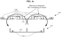
- FIG. 1c shows a cross section of FIG. 1b cut along a line A-A', seen from an X direction.
- FIG. 1c reference numerals are not shown in detail to mainly show a magnetic field. A description of FIG. 1c will be made with reference to the reference numerals of FIG. 1b .
- a magnetic flux is generated by the feed line 114 in an arrowed direction as shown in FIG. 1c , thereby generating an induced electromotive force at the current collecting line 134.
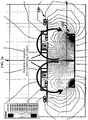
- FIG. 2 shows a magnetic field generated according to relations among the feed core 112, the feed line 114, and the current collecting apparatus 130 of FIG. 1c .
- FIG. 2 shows arrangement of the feed core 112, the feed line 114, and the current collecting apparatus 130 and a magnetic field generated in a case in which the electric car 100 runs on the road such that the current collecting apparatus 130 of the electric car 100 is disposed at an upper part of a middle of the feed core 112 and the feed line 114 embedded in the road, that is, when the current collecting apparatus 130 is disposed in a correct position, to be supplied with maximum power.
- B of FIG.
- FIG. 2 shows arrangement of the feed core 112, the feed line 114, and the current collecting apparatus 130 and a magnetic field generated in a case in which the current collecting apparatus 130 is deviated by a predetermined distance to the left or the right from the middle of the feed core 112 and the feed line 114, that is, when the current collecting apparatus 130 is misaligned.
- output of the induced electromotive force may be generated in a normal amount at a current collecting line 134 coiled on a current collecting core 132.
- An arrow shown as a semicircle in (A) of FIG. 2 conceptually denotes a direction of the magnetic field contributing to the induced electromotive force of the current collecting apparatus 130.
- feed line configuration is given in the following article: Seungyoung Ahn & al., “Low Frequency Electromagnetic Field Reduction Techniques for the On-Line Electric Vehicle (OLEV)", 2010 IEEE International Symposium on Electromagnetic Compatibility, 625-630 .
- OLEV On-Line Electric Vehicle
- An object of the present invention is to solve the above problems and to efficiently supply power necessary for operation of a moving medium such as an electric car even when a current collecting apparatus mounted to the moving medium supplied with the power through recharging during running on a road is deviated from a feed line embedded in the road by a predetermined distance to the left or the right.
- Another object of the present invention is to considerably reduce a use amount of a core while not much reducing power transmission efficiency, by providing a cut unit to a feed core.
- a current feed apparatus including a feed core including a main feed unit having a predetermined width and length, feed projection units projected from a cross section of the main feed unit, which is perpendicular to both a width direction and a length direction of the main feed unit, at a left end and a right end of the width direction in a same direction, and a middle projection unit projected in the same direction as the feed projection units in a middle of a width direction of the main feed unit accordingly being formed into an E shape, and a pair of feed lines wound on a left end and a right end of the main feed unit.
- the feed lines are wound adjacent to the feed projection units.
- the feed core may include a plurality of cut units parallel with the width direction and therefore the feed core is divided into a plurality of core pieces.
- a thickness of the cut units of the feed core may be greater than a thickness of the core pieces.
- a current collecting apparatus including a collecting core including a main collecting unit having a predetermined width and length, and collecting projection units projected from a cross section of the main feed unit, which is perpendicular to both a width direction and a length direction of the main collecting unit in the same direction at a left end and a right end of the width direction, thereby being formed into an inverted U shape, and a collecting line wound on the collecting core.
- the collecting line may be wound on the collecting projection units projected at the left end and the right end.
- the collecting core may include extension units extended in the width direction from ends of the collecting projection units projected at the left and the right end.
- the current collecting apparatus may be mounted to a lower part of a car.
- a power transmission unit including the current feed apparatus according to any one of claim 1 to claim 3, and the current collecting apparatus according to any one of claim 4 to claim 7, wherein the feed projection units and the collecting projection units are projected to face each other.
- a feed core is provided with a cut unit, a use amount of a core may be considerably reduced while power transmission efficiency is not much reduced.
- FIG. 3a is a diagram of a power transmission apparatus according to a first embodiment of the present invention.
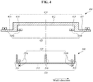
- FIG. 4 is a diagram of a cross section of FIG. 3a cut along a line A-A', seen from an X direction.
- FIG. 3b is a diagram of a feed core integrally formed in an inverted U shape without a cut unit and a feed core integrally formed in an E shape without a cut unit.
- the power transmission apparatus includes a current feed apparatus 300 and a current collecting apparatus 400.
- the current feed apparatus 300 may include a feed core 310, a feed line 320, and an input power 330.
- the current collecting apparatus 400 according to the first embodiment may include a collecting core 410, a collecting line 420, a collecting circuit 430, and a battery 440.
- the feed core 310 may include a main feed unit 312 having a predetermined width and length, and feed projection units 314 and 315 projected from a cross section of the main feed unit 312, which is perpendicular to a length direction of the feed core 310, at a left end and a right end of a width direction of the feed core 310.
- the feed projection units 314 and 315 are perpendicular to both the width direction and the length direction of the feed core 310, so that the feed core 310 is formed into a U shape. Since the feed core 310 includes the feed projection units 314 and 315, the magnetic field may be easily transferred to the current collecting apparatus 400.
- the feed core 310 further includes a middle projection unit 316 projected in the same direction as the feed projection units 314 and 315 in the middle of the width direction of the main feed unit 312, so that the feed core 310 is formed into an laid E shape. In this case, an entire amount of the magnetic field transferred to the current collecting apparatus 400 may be increased in comparison to when the feed core 310 is in the U shape.
- a pair of feed lines 320 may be wound on a left end and a right end of the main feed unit 312.
- a left feed line 320a is wound on the left end of the main feed unit 312 in the length direction of the feed core 310 to be adjacent to the left feed projection unit 314.
- a right feed line 320b is wound on the right end of the main feed unit 312 in the length direction of the feed core 310 to be adjacent to the right feed projection unit 315.
- the pair of feed lines 320a and 320b may be wound on the left feed projection unit 314 and the right feed projection unit 315, respectively.
- the feed core 310 may be integrally formed as shown in FIG. 3b , or may include a cut unit 340 as shown in FIG. 3a .
- the feed core 310 may include a plurality of cut units 340 parallel with the width direction of the feed core 310. Therefore, the feed core 310 may be divided into a plurality of core pieces each in an E shape or a U shape.
- intervals between neighboring cut units 340 may be uniform.
- a thickness of the cut units 340 may be similar to or greater or smaller than a thickness of the core pieces in the E shape.
- an output induced to the current collecting apparatus 400 may be reduced by about 10% in comparison to the case of FIG. 3a .
- a capacity of a ferrite core used for the feed core 310 may be reduced almost to a half in this case, reduction in the output induced to the current collecting apparatus 400 is not greater than the reduced ferrite capacity. That is, economical efficiency is relatively high.
- the collecting core 410 may include a main collecting unit 412 having a predetermined width and length, and collecting projection units 414 and 415 projected from the main collecting unit 412 in the same direction at a left end and a right end of a width direction of the collecting core 410.
- the collecting projection units 414 and 415 are projected perpendicular to both the width direction and the length direction of the collecting core 410, so that a cross section of the main collecting unit 412 perpendicular to the length direction of the collecting core 410 is an inverted U shape.
- the collecting projection units 414 and 415 may be projected in an opposite direction to a projection direction of the feed projection units 314 and 315.
- extension units 416 and 417 may be extended in the width direction of the collecting core 410, respectively.
- the collecting projection units 414 and 415 may increase an effective sectional area on a magnetic path, thereby reducing a magnetic resistance.
- the extension units may be extended outward from the collecting projection units 414 and 415 with respect to the main collecting unit 412 as indicated by reference numerals 416 and 417.
- the extension units 416 and 417 may additionally include a projection part projected in a direction from the collecting projection units 414 and 415 toward a center of the main collecting unit 412, that is, in an opposite direction to the reference numerals 416 and 417 with reference to the collecting projection units 414 and 415, with respect to the width direction of the collecting core 410.
- the collecting line 420 may be wound on a left collecting projection unit 414 and a right collecting projection unit 415 of the collecting core 410, or on the main collecting unit 412.
- Collecting lines 420a and 420b wound on the left and right collecting projection units 414 and 415 of the collecting core 410 may be connected parallel with the collecting circuit 430 to generate desired levels of voltage and charge the battery 440 connected to the collecting lines 420a and 420b.
- the collecting circuit 430 may include a rectifier and a regulator.
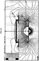
- FIG. 5 is a diagram showing a magnetic field generated in the power transmission apparatus shown in FIGS. 3a and 4 . Reference numerals are omitted from FIG. 5 to mainly describe the magnetic field. Reference numerals of FIG. 4 will be cited for a description of FIG. 5 .
- output of the induced electromotive force may be generated at the collecting line 420 wound on the collecting core 410 in a normal amount.
- An arrow shown as a semicircle in (A) of FIG. 5 conceptually denotes a direction of a magnetic field contributing to the induced electromotive force of the current collecting apparatus 400.
- an output of the collecting line 134 is simulated under conditions in which a width of the feed core 110 is 72 cm, a width of the current collecting apparatus 130 is 110 cm, and the current collecting apparatus 130 is disposed in the correct position as shown in (A) of FIG. 2 .
- a sum of voltages generated at the collecting line 134 is 1651 V
- a misaligned distance of the current collecting apparatus 130 is 30 cm as in (B) of FIG. 2
- a sum of voltages generated at the collecting line 134 becomes about 148 V. That is, the generated voltage is greatly reduced. Since an induced current is reduced according to reduction in the voltage induced to the current collecting apparatus 130, output induced to the current collecting apparatus 130 is abruptly reduced.
- FIG. 6 is a diagram of a power transmission apparatus according to a second embodiment of the present invention.
- FIG. 7 is a diagram of a cross section of FIG. 6 cut along a line A-A', seen from an X direction
- the power transmission apparatus includes a current feed apparatus 600 and a current collecting apparatus 700.
- a feed line 620 may be wound in a length direction of the feed core 610 in a middle of a main feed unit 612 with respect to a width direction of the main feed unit 612.
- Collecting lines 720a and 720b wound on the left and right collecting projection units 714 and 715 of the collecting core 710 may be connected parallel with the collecting circuit 730 to generate desired levels of voltage and to charge the battery 740 connected to the collecting lines 420a and 420b. Since configuration and function of the current collecting apparatus 600 are similar to those of the current collecting apparatus 400 of FIGS. 3a and 4 , a detailed description will be omitted.
- FIG. 8 is a diagram showing a magnetic field generated in the power transmission apparatus shown in FIGS. 6 and 7 . Reference numerals are omitted from FIG. 7 to mainly describe the magnetic field. Reference numerals of FIG. 7 will be cited for a description of FIG. 8 .
- FIG. 8 shows a magnetic field generated when a middle of the current collecting apparatus 700 with respect to a width direction is disposed on an upper portion of a middle of the current feed apparatus 600 with respect to a width direction, that is, when the current collecting apparatus 700 is in a correct position to be supplied with maximum power.
- (B) of FIG. 8 shows a magnetic field generated when the current collecting apparatus 700 is misaligned.
- output of the induced electromotive force may be generated at the collecting line 720 wound on the collecting core 710 in a normal amount.
- An arrow shown as a semicircle in (A) of FIG. 8 conceptually denotes a direction of a magnetic field contributing to the induced electromotive force of the current collecting apparatus 700.
- the power transmission apparatus configured as in FIG. 8
- a voltage of about 2782 V is generated at the current collecting apparatus 700 under the same conditions as FIG. 5 , in which the width of the feed core 610 is 72 cm, a width of the current collecting apparatus 700 is 110 cm, and the current collecting apparatus 700 is in the correct position as shown in (A) of FIG. 8
- a misaligned distance of the current collecting apparatus 700 is 30 cm as in (B) of FIG. 8
- a voltage generated of the current collecting apparatus 700 becomes about 1870 V. That is, the generated voltage is not reduced by a large degree. Therefore, the power transmission apparatus of FIG. 8 is efficient than the power transmission apparatus of (B) of FIG. 2 .
- the output voltage maintain ratio of misalignment with respect to correct position is no more than 9.0 % in FIG. 2 and therefore it is difficult to efficiently generate the induced electromotive force at the current collecting apparatus.
- the output voltage maintain ratios are 75.9 % and 67.2 %, respectively. That is, it is understood that a considerable level of the induced electromotive force is generated at the current collecting apparatus in spite of the misalignment of the current collecting apparatus.
- the present invention is effective since power necessary power necessary for operation of a moving medium such as an electric car is efficiently supplied even when the moving medium, which is supplied with the power through recharging during running on a road, is deviated from a feed line embedded in the road by a predetermined distance to the left or the right.
Landscapes
- Engineering & Computer Science (AREA)
- Power Engineering (AREA)
- Mechanical Engineering (AREA)
- Transportation (AREA)
- Computer Networks & Wireless Communication (AREA)
- Current-Collector Devices For Electrically Propelled Vehicles (AREA)
- Charge And Discharge Circuits For Batteries Or The Like (AREA)
- Electric Propulsion And Braking For Vehicles (AREA)
Description
- The present invention relates to a current feed apparatus, a current collecting apparatus, and a power transmission apparatus of a magnetic induction type, considering lateral deviation, and more particularly, to a current feed apparatus, a current collecting apparatus, and a power transmission apparatus of a magnetic induction type, considering lateral deviation, capable of efficiently supplying power necessary for operation of a moving medium such as an electric car even when the moving medium, which is supplied with the power through recharging during running on a road, is deviated from a feed line embedded in the road by a predetermined distance to the left or the right.
- Elements described herein only provide background information related to the embodiment of the present invention rather than constituting a conventional art.
-
FIG. 1a shows an electric car running on a road while being supplied with power through a feed line embedded in the road.FIG. 1b simply shows a feed core, a feed line, and a current collecting apparatus necessary for power transmission, excluding the electric car and the road ofFIG. 1a . - As shown in
FIGS. 1a and 1b , when a high frequency power is supplied to afeed line 114 disposed at an upper part of afeed core 112 while anelectric car 100 is running on the road, theelectric car 100 is supplied with power necessary for running according to the electromagnetic induction principle operating between thecurrent feed apparatus 110 that includes thefeed core 112 and thefeed line 114 and thecurrent collecting apparatus 130. -
FIG. 1c shows a cross section ofFIG. 1b cut along a line A-A', seen from an X direction. - In
FIG. 1c , reference numerals are not shown in detail to mainly show a magnetic field. A description ofFIG. 1c will be made with reference to the reference numerals ofFIG. 1b . - A magnetic flux is generated by the
feed line 114 in an arrowed direction as shown inFIG. 1c , thereby generating an induced electromotive force at thecurrent collecting line 134. -
FIG. 2 shows a magnetic field generated according to relations among thefeed core 112, thefeed line 114, and the current collectingapparatus 130 ofFIG. 1c . - (A) of
FIG. 2 shows arrangement of thefeed core 112, thefeed line 114, and thecurrent collecting apparatus 130 and a magnetic field generated in a case in which theelectric car 100 runs on the road such that the current collectingapparatus 130 of theelectric car 100 is disposed at an upper part of a middle of thefeed core 112 and thefeed line 114 embedded in the road, that is, when thecurrent collecting apparatus 130 is disposed in a correct position, to be supplied with maximum power. (B) ofFIG. 2 shows arrangement of thefeed core 112, thefeed line 114, and thecurrent collecting apparatus 130 and a magnetic field generated in a case in which thecurrent collecting apparatus 130 is deviated by a predetermined distance to the left or the right from the middle of thefeed core 112 and thefeed line 114, that is, when the current collectingapparatus 130 is misaligned. - When the
current collecting apparatus 130 is disposed at the upper part of the middle of thecurrent feed apparatus 110 during running of theelectric car 100 as shown in (A) ofFIG. 2 , output of the induced electromotive force may be generated in a normal amount at acurrent collecting line 134 coiled on a current collectingcore 132. An arrow shown as a semicircle in (A) ofFIG. 2 conceptually denotes a direction of the magnetic field contributing to the induced electromotive force of thecurrent collecting apparatus 130. - In the case of (B) of
FIG. 2 , when theelectric car 100 runs so that a misalignment distance of the current collectingapparatus 130 becomes a predetermined distance or more, a magnetic flux not contributing to the induced electromotive force is increased and, furthermore, a magnetic flux of an opposite direction to the magnetic flux contributing to the induced electromotive force is increased. As a result, power transmission from thecurrent feed apparatus 110 to thecurrent collecting 130 may not be favorably performed. - Another example of feed line configuration is given in the following article: Seungyoung Ahn & al., "Low Frequency Electromagnetic Field Reduction Techniques for the On-Line Electric Vehicle (OLEV)", 2010 IEEE International Symposium on Electromagnetic Compatibility, 625-630.
- An object of the present invention is to solve the above problems and to efficiently supply power necessary for operation of a moving medium such as an electric car even when a current collecting apparatus mounted to the moving medium supplied with the power through recharging during running on a road is deviated from a feed line embedded in the road by a predetermined distance to the left or the right.
- In addition, another object of the present invention is to considerably reduce a use amount of a core while not much reducing power transmission efficiency, by providing a cut unit to a feed core.
- The technical solution is achieved by the current feed apparatus of Claim 1.
- According to an aspect of the present invention, there is provided a current feed apparatus including a feed core including a main feed unit having a predetermined width and length, feed projection units projected from a cross section of the main feed unit, which is perpendicular to both a width direction and a length direction of the main feed unit, at a left end and a right end of the width direction in a same direction, and a middle projection unit projected in the same direction as the feed projection units in a middle of a width direction of the main feed unit accordingly being formed into an E shape, and a pair of feed lines wound on a left end and a right end of the main feed unit.
- The feed lines are wound adjacent to the feed projection units.
- The feed core may include a plurality of cut units parallel with the width direction and therefore the feed core is divided into a plurality of core pieces.
- A thickness of the cut units of the feed core may be greater than a thickness of the core pieces.
- According to another aspect of the present invention, there is provided a current collecting apparatus including a collecting core including a main collecting unit having a predetermined width and length, and collecting projection units projected from a cross section of the main feed unit, which is perpendicular to both a width direction and a length direction of the main collecting unit in the same direction at a left end and a right end of the width direction, thereby being formed into an inverted U shape, and a collecting line wound on the collecting core.
- The collecting line may be wound on the collecting projection units projected at the left end and the right end.
- The collecting core may include extension units extended in the width direction from ends of the collecting projection units projected at the left and the right end.
- The current collecting apparatus may be mounted to a lower part of a car.
- According to another aspect of the present invention, there is provided a power transmission unit including the current feed apparatus according to any one of claim 1 to claim 3, and the current collecting apparatus according to any one of claim 4 to claim 7, wherein the feed projection units and the collecting projection units are projected to face each other.
- As described above, according to an embodiment of the present invention, when a moving medium such as an electric car, which is supplied with power necessary for operation through recharging during running on a road, is deviated from a feed line embedded in the road by a predetermined distance to the left or the right, the power necessary for operation may be efficiently supplied.
- In addition, since a feed core is provided with a cut unit, a use amount of a core may be considerably reduced while power transmission efficiency is not much reduced.
-
-
FIG. 1a is a diagram showing an electric car running on a road while being supplied with power through a feed line embedded in the road; -
FIG. 1b is a simplified diagram showing a feed core, a feed line, and a current collecting apparatus necessary for power transmission, excluding the electric car and the road ofFIG. 1a ; -
FIG. 1c is a diagram of a cross section ofFIG. 1b cut along a line A-A', seen from an X direction; -
FIG. 2 is a diagram showing a magnetic field generated according to relations among the feed core, the feed line, and the current collecting apparatus ofFIG. 1c ; -
FIG. 3a is a diagram of a power transmission apparatus according to a first embodiment of the present invention; -
FIG. 3b is a diagram of a feed core integrally formed in an inverted U shape without a cut unit, and a feed core integrally formed in an E shape without a cut unit. -
FIG. 4 is a diagram of a cross section ofFIG. 3a cut along a line A-A', seen from an X direction; -
FIG. 5 is a diagram showing a magnetic field generated in the power transmission apparatus shown inFIGS. 3a and4 ; -
FIG. 6 is a diagram of a power transmission apparatus according to a second embodiment of the present invention; -
FIG. 7 is a diagram of a cross section ofFIG. 6 cut along a line A-A', seen from an X direction; and -
FIG. 8 is a diagram showing a magnetic field generated in the power transmission apparatus shown inFIGS. 6 and7 . - Reference will now be made in detail to embodiments of the present invention, examples of which are illustrated in the accompanying drawings, wherein like reference numerals refer to the like elements throughout. The embodiments are described below in order to explain the present invention by referring to the figures. However, in explaining the embodiments of the present invention, generally known functions and structures will not be explained in detail for conciseness.
- In addition, in describing elements of the present invention, terms such as "first," "second," "A," "B," "(a)," and "(b)" may be used. Since those terms are used only to distinguish the corresponding elements from others, attributes or orders of the elements are not limited by those terms. In the specification, it will be understood that when an element is referred to as being "connected" or "coupled" to another element, it can be directly connected or coupled to the other element, or intervening elements may also be present.
-
FIG. 3a is a diagram of a power transmission apparatus according to a first embodiment of the present invention.FIG. 4 is a diagram of a cross section ofFIG. 3a cut along a line A-A', seen from an X direction.FIG. 3b is a diagram of a feed core integrally formed in an inverted U shape without a cut unit and a feed core integrally formed in an E shape without a cut unit. - The power transmission apparatus according to first embodiment of the present invention will now be described with reference to
FIGS. 3a ,3b , and4 . - As shown in
FIGS. 3a and4 , the power transmission apparatus includes acurrent feed apparatus 300 and acurrent collecting apparatus 400. - The
current feed apparatus 300 according to the first embodiment may include afeed core 310, afeed line 320, and aninput power 330. Thecurrent collecting apparatus 400 according to the first embodiment may include a collectingcore 410, acollecting line 420, a collectingcircuit 430, and abattery 440. - The
feed core 310 may include amain feed unit 312 having a predetermined width and length, and feedprojection units main feed unit 312, which is perpendicular to a length direction of thefeed core 310, at a left end and a right end of a width direction of thefeed core 310. Thefeed projection units feed core 310, so that thefeed core 310 is formed into a U shape. Since thefeed core 310 includes thefeed projection units current collecting apparatus 400. - The
feed core 310 further includes amiddle projection unit 316 projected in the same direction as thefeed projection units main feed unit 312, so that thefeed core 310 is formed into an laid E shape. In this case, an entire amount of the magnetic field transferred to thecurrent collecting apparatus 400 may be increased in comparison to when thefeed core 310 is in the U shape. - A pair of
feed lines 320 may be wound on a left end and a right end of themain feed unit 312. - A
left feed line 320a is wound on the left end of themain feed unit 312 in the length direction of thefeed core 310 to be adjacent to the leftfeed projection unit 314. Aright feed line 320b is wound on the right end of themain feed unit 312 in the length direction of thefeed core 310 to be adjacent to the rightfeed projection unit 315. Depending on cases, the pair offeed lines feed projection unit 314 and the rightfeed projection unit 315, respectively. - The
feed core 310 may be integrally formed as shown inFIG. 3b , or may include acut unit 340 as shown inFIG. 3a . - The
feed core 310 may include a plurality ofcut units 340 parallel with the width direction of thefeed core 310. Therefore, thefeed core 310 may be divided into a plurality of core pieces each in an E shape or a U shape. - Here, as shown in
FIG. 3a , intervals between neighboring cutunits 340 may be uniform. A thickness of thecut units 340 may be similar to or greater or smaller than a thickness of the core pieces in the E shape. - When the
cut units 340 are provided at thefeed core 310 as shown inFIG. 3a and thefeed core 310 is formed with only a half capacity of theintegral feed core 310 as shown inFIG. 3b , an output induced to thecurrent collecting apparatus 400 may be reduced by about 10% in comparison to the case ofFIG. 3a . However, since a capacity of a ferrite core used for thefeed core 310 may be reduced almost to a half in this case, reduction in the output induced to thecurrent collecting apparatus 400 is not greater than the reduced ferrite capacity. That is, economical efficiency is relatively high. - The collecting
core 410 may include amain collecting unit 412 having a predetermined width and length, and collectingprojection units main collecting unit 412 in the same direction at a left end and a right end of a width direction of the collectingcore 410. The collectingprojection units core 410, so that a cross section of themain collecting unit 412 perpendicular to the length direction of the collectingcore 410 is an inverted U shape. Here, the collectingprojection units feed projection units - At ends of the collecting
projection units extension units core 410, respectively. By including theextension units projection units - The extension units may be extended outward from the collecting
projection units main collecting unit 412 as indicated byreference numerals extension units projection units main collecting unit 412, that is, in an opposite direction to thereference numerals projection units core 410. - The collecting
line 420 may be wound on a leftcollecting projection unit 414 and a rightcollecting projection unit 415 of the collectingcore 410, or on themain collecting unit 412. - When the
input power 330 is applied to thefeed line 320 ofFIG. 3a , a magnetic field is generated at thefeed line 320, and an induced electromotive force is generated at thecollecting line 420, being induced from the magnetic field. Collectinglines projection units core 410 may be connected parallel with the collectingcircuit 430 to generate desired levels of voltage and charge thebattery 440 connected to thecollecting lines circuit 430 may include a rectifier and a regulator. -
FIG. 5 is a diagram showing a magnetic field generated in the power transmission apparatus shown inFIGS. 3a and4 . Reference numerals are omitted fromFIG. 5 to mainly describe the magnetic field. Reference numerals ofFIG. 4 will be cited for a description ofFIG. 5 . - (A) of
FIG. 5 shows a magnetic field generated when thecurrent collecting apparatus 400 is disposed in a correct position, to be supplied with maximum power. - (B) of
FIG. 5 shows a magnetic field generated when thecurrent collecting apparatus 400 is misaligned. - When the
current collecting apparatus 400 is in the correct position as in (A) ofFIG. 5 , output of the induced electromotive force may be generated at thecollecting line 420 wound on the collectingcore 410 in a normal amount. An arrow shown as a semicircle in (A) ofFIG. 5 conceptually denotes a direction of a magnetic field contributing to the induced electromotive force of thecurrent collecting apparatus 400. - When the
current collecting apparatus 400 is misaligned as shown in (B) ofFIG. 5 , an amount of a magnetic flux not contributing to the induced electromotive force is increased but, however, an amount of a magnetic flux of an opposite direction to the magnetic flux contributing to the induced electromotive force is not great. - In the power transmission apparatus configured as in
FIG. 2 , an output of thecollecting line 134 is simulated under conditions in which a width of thefeed core 110 is 72 cm, a width of thecurrent collecting apparatus 130 is 110 cm, and thecurrent collecting apparatus 130 is disposed in the correct position as shown in (A) ofFIG. 2 . As a result of the simulation, when a sum of voltages generated at thecollecting line 134 is 1651 V, when a misaligned distance of thecurrent collecting apparatus 130 is 30 cm as in (B) ofFIG. 2 , a sum of voltages generated at thecollecting line 134 becomes about 148 V. That is, the generated voltage is greatly reduced. Since an induced current is reduced according to reduction in the voltage induced to thecurrent collecting apparatus 130, output induced to thecurrent collecting apparatus 130 is abruptly reduced. - However, in the power transmission apparatus configured as in
FIG. 5 , when a sum of voltages generated at thecollecting line 420 is 1726 V as a result of simulation under the same conditions asFIG. 2 , in which the width of thefeed core 310 is 72 cm and a width of thecurrent collecting apparatus 400 is 110 cm, and when a misaligned distance of thecurrent collecting apparatus 400 is 30 cm as in (B) ofFIG. 2 , a sum of voltages generated at thecollecting line 420 becomes about 1559 V. That is, the generated voltage is not reduced by a large degree. Therefore, the power transmission apparatus ofFIG. 5 is efficient than the power transmission apparatus of (B) ofFIG. 2 . -
FIG. 6 is a diagram of a power transmission apparatus according to a second embodiment of the present invention.FIG. 7 is a diagram of a cross section ofFIG. 6 cut along a line A-A', seen from an X direction - As shown in
FIGS. 6 and7 , the power transmission apparatus according to the second embodiment includes acurrent feed apparatus 600 and acurrent collecting apparatus 700. - In
FIGS. 6 and7 , since afeed core 610 is configured similar to thefeed core 300 ofFIGS. 3a and4 , a detailed description about thefeed core 610 will be omitted. - A
feed line 620 may be wound in a length direction of thefeed core 610 in a middle of amain feed unit 612 with respect to a width direction of themain feed unit 612. - When an
input power 630 is applied to thefeed line 620 ofFIG. 6 , a magnetic field is generated at thefeed line 620, and an induced electromotive force is generated at acollecting line 720, being induced from the magnetic field. Collectinglines projection units core 710 may be connected parallel with the collectingcircuit 730 to generate desired levels of voltage and to charge thebattery 740 connected to thecollecting lines current collecting apparatus 600 are similar to those of thecurrent collecting apparatus 400 ofFIGS. 3a and4 , a detailed description will be omitted. -
FIG. 8 is a diagram showing a magnetic field generated in the power transmission apparatus shown inFIGS. 6 and7 . Reference numerals are omitted fromFIG. 7 to mainly describe the magnetic field. Reference numerals ofFIG. 7 will be cited for a description ofFIG. 8 . - (A) of
FIG. 8 shows a magnetic field generated when a middle of thecurrent collecting apparatus 700 with respect to a width direction is disposed on an upper portion of a middle of thecurrent feed apparatus 600 with respect to a width direction, that is, when thecurrent collecting apparatus 700 is in a correct position to be supplied with maximum power. (B) ofFIG. 8 shows a magnetic field generated when thecurrent collecting apparatus 700 is misaligned. - When the
current collecting apparatus 700 is in the correct position as shown in (A) ofFIG. 8 , output of the induced electromotive force may be generated at thecollecting line 720 wound on the collectingcore 710 in a normal amount. An arrow shown as a semicircle in (A) ofFIG. 8 conceptually denotes a direction of a magnetic field contributing to the induced electromotive force of thecurrent collecting apparatus 700. - When the
current collecting apparatus 700 is misaligned as shown in (B) ofFIG. 8 , an amount of a magnetic flux not contributing to the induced electromotive force is increased but, however, an amount of a magnetic flux of an opposite direction to the magnetic flux contributing to the induced electromotive force is relatively low. Therefore, voltage reduction of thecurrent collecting apparatus 130 may be smaller than when thecurrent collecting apparatus 130 ofFIG. 2 is misaligned. - For example, in the power transmission apparatus configured as in
FIG. 8 , when a voltage of about 2782 V is generated at thecurrent collecting apparatus 700 under the same conditions asFIG. 5 , in which the width of thefeed core 610 is 72 cm, a width of thecurrent collecting apparatus 700 is 110 cm, and thecurrent collecting apparatus 700 is in the correct position as shown in (A) ofFIG. 8 , and when a misaligned distance of thecurrent collecting apparatus 700 is 30 cm as in (B) ofFIG. 8 , a voltage generated of thecurrent collecting apparatus 700 becomes about 1870 V. That is, the generated voltage is not reduced by a large degree. Therefore, the power transmission apparatus ofFIG. 8 is efficient than the power transmission apparatus of (B) ofFIG. 2 . - In
FIGS. 2 ,5 , and8 , output voltages of the induced electromotive force are compared between a case in which thecurrent collecting apparatus 700 is in the correct position and a case in which thecurrent collecting apparatus 700 is deviated by 30 cm, resulting in Table 1.[Table 1] Output voltage in correct position Output voltage with 30 cm misalignment distance Output voltage maintain ratio of misalignment with respect to correct position FIG. 2 1651 V 148 V 9.0% FIG. 5 2063 V 1559 V 75.9% FIG. 8 2782 V 1870 V 67.2% - As shown in Table 1, the output voltage maintain ratio of misalignment with respect to correct position is no more than 9.0 % in
FIG. 2 and therefore it is difficult to efficiently generate the induced electromotive force at the current collecting apparatus. However, inFIGS. 5 and8 , the output voltage maintain ratios are 75.9 % and 67.2 %, respectively. That is, it is understood that a considerable level of the induced electromotive force is generated at the current collecting apparatus in spite of the misalignment of the current collecting apparatus. - In the foregoing, although the elements of the present invention have been described as being integrally coupled or operating integrally, the present invention is not limited to the embodiments. That is, within the scope of the invention, at least one of the elements may be selectively coupled and operated.
- Furthermore, when it is described that one comprises (or includes or has) some elements, it should be understood that it may comprise (or include or has) only those elements, or it may comprise (or include or have) other elements as well as those elements if there is no specific limitation. Unless otherwise specifically defined herein, all terms including technical or scientific terms are to be given meanings understood by those skilled in the art. Like terms defined in dictionaries, generally used terms needs to be construed as meaning used in technical contexts and are not construed as ideal or excessively formal meanings unless otherwise clearly defined herein.
- Embodiments described above only by way of example and are not to limit the scope of the invention. Those skilled in the art may use the methods and technical disclosure described herein to make various alternations and modifications to the disclosure without departing from the scope of the invention. Therefore, the above embodiments are only used for describing the technical concept of the invention rather than limiting the protection range of the invention, and all the equivalent changes shall be considered within the protection range of the invention.
- As described above, the present invention is effective since power necessary power necessary for operation of a moving medium such as an electric car is efficiently supplied even when the moving medium, which is supplied with the power through recharging during running on a road, is deviated from a feed line embedded in the road by a predetermined distance to the left or the right.
Claims (7)
- A current feed apparatus comprising:a feed core (310) including a main feed unit (312) having a predetermined width in a width direction and length in a length direction, feed projection units (314, 315, 316) projected from the main feed unit (312), which feed projection units are arranged perpendicular to both said width direction and said length direction of the main feed unit (312), and comprise a first feed projection unit (314) at a first, left, end of said main feed unit (312) and a second feed projection unit (315) at a second, right, end of said main feed unit (312; 612) as seen in the width direction, and a middle feed projection unit (316) arranged in a middle of the main feed unit (312) seen in said width direction and projecting in the same direction as the first and second feed projection units, said first end being opposite to said second end such that said main feed unit (312) and said first (314), second (315) and middle (316) feed projection units form an E shape; andfeed lines being wound on the feed core,characterized in thatsaid feed lines comprising a pair of feed lines comprising a first, left, feed line (320a) and a second, right, feed line (320b), arranged such thatsaid middle feed projection unit (316) having no feed line wound on it.said first, left, feed line (320a) is wound on the first, left, end of the main feed unit (312) in the length direction of the feed core (310) adjacent to the first feed projection unit (314), and said second, right, feed line (320b) is wound on the second, right, end of the main feed unit (312) in the length direction of the feed core (310) adjacent to the second feed projection unit (315); and
- The current feed apparatus of claim 1, wherein the feed core comprises a plurality of cut units parallel with the width direction and therefore the feed core is divided into a plurality of core pieces.
- The current feed apparatus of claim 2, wherein a thickness of the cut units of the feed core is greater than a thickness of the core pieces.
- A power transmission system comprising:the current feed apparatus according to any one of claim 1 to claim 3, anda current collecting apparatus comprising:a collecting core (410) including a main collecting unit (412) having a predetermined further width in a further width direction and a further length in a further length direction, and collecting projection units (414, 415) projecting in the same direction from the main collecting unit (412) perpendicular to both said further width direction and said further length direction of the main collecting unit (412) at a first, left, end and a second, right, end of the further width direction, such that the main collecting unit (412) and the collecting projection units (414, 415) form an inverted U shape; anda collecting line wound on the collecting core.
- The power transmission system of claim 4, wherein the collecting line is wound on the collecting projection units projected at the left end and the right end.
- The power transmission system of claim 4, wherein the collecting core comprises respective extension units (416, 417) extending in the width direction from ends of the respective collecting projection units (414, 415).
- The power transmission system of claim 4, wherein the current collecting apparatus is mounted to a lower part of a car.
Applications Claiming Priority (2)
| Application Number | Priority Date | Filing Date | Title |
|---|---|---|---|
| KR1020110039206A KR101182376B1 (en) | 2011-04-26 | 2011-04-26 | Magnetic Inductive Apparatus for Power Transmission, Power Collection and Power Transmission Considering Horizontal Deviation |
| PCT/KR2012/003181 WO2012148164A1 (en) | 2011-04-26 | 2012-04-25 | Feed apparatus, current collector, and power transfer apparatus of the magnetic induction type, considering lateral deviation |
Publications (3)
| Publication Number | Publication Date |
|---|---|
| EP2704292A1 EP2704292A1 (en) | 2014-03-05 |
| EP2704292A4 EP2704292A4 (en) | 2015-06-24 |
| EP2704292B1 true EP2704292B1 (en) | 2017-04-05 |
Family
ID=47072566
Family Applications (1)
| Application Number | Title | Priority Date | Filing Date |
|---|---|---|---|
| EP12777602.9A Active EP2704292B1 (en) | 2011-04-26 | 2012-04-25 | Feed apparatus, current collector, and power transfer apparatus of the magnetic induction type, considering lateral deviation |
Country Status (7)
| Country | Link |
|---|---|
| US (1) | US9656562B2 (en) |
| EP (1) | EP2704292B1 (en) |
| JP (1) | JP2014515247A (en) |
| KR (1) | KR101182376B1 (en) |
| CN (1) | CN103548236B (en) |
| AU (1) | AU2012248971B2 (en) |
| WO (1) | WO2012148164A1 (en) |
Families Citing this family (11)
| Publication number | Priority date | Publication date | Assignee | Title |
|---|---|---|---|---|
| KR101438394B1 (en) * | 2012-11-19 | 2014-09-17 | 한국과학기술원 | Power Rail and Pickup Robust to Direction of Vehicle at Stop and Move |
| KR101384691B1 (en) * | 2012-11-23 | 2014-04-21 | 한국과학기술원 | Slim type pickup for vehicle |
| KR102238917B1 (en) * | 2014-01-27 | 2021-04-13 | 한국과학기술원 | Wireless Electric Power Supply Device having Magnetic Shield |
| US9522604B2 (en) * | 2014-08-04 | 2016-12-20 | Ford Global Technologies, Llc | Inductive wireless power transfer system having a coupler assembly comprising moveable permeable panels |
| KR101657570B1 (en) * | 2014-08-19 | 2016-09-20 | 한국과학기술원 | pickup with core slit for wireless power transmission system weight reduction |
| KR101589609B1 (en) * | 2014-08-21 | 2016-01-29 | 한국과학기술원 | Wireless Electric Power Supply Apparatus |
| WO2017116333A1 (en) * | 2015-12-30 | 2017-07-06 | Gebze Teknik Universitesi | A charging system for wireless charging of electric vehicles and an electric vehicle operating suitably with this system |
| EP3188198A1 (en) * | 2015-12-31 | 2017-07-05 | Schneeberger Holding AG | Device for contactless transmission of electric energy into a moving system of a sliding device |
| US11526176B2 (en) * | 2017-02-14 | 2022-12-13 | Volvo Truck Corporation | Sensing arrangement for determining a displacement of a vehicle with respect to an electrical road system |
| KR102611133B1 (en) | 2017-12-12 | 2023-12-07 | 한국과학기술원 | Apparatus for wireless power transfer to a moving vehicle having robustness to deviation |
| CN112977102A (en) * | 2021-04-19 | 2021-06-18 | 国网黑龙江省电力有限公司电力科学研究院 | Dynamic resonant magnetic coupling wireless charging system for electric automobile |
Family Cites Families (24)
| Publication number | Priority date | Publication date | Assignee | Title |
|---|---|---|---|---|
| JPS5592504A (en) * | 1978-04-25 | 1980-07-14 | Bolger John George | Vehicle used on road in combination with electric power source for generating magnetic field |
| SU889498A1 (en) * | 1980-03-27 | 1981-12-15 | Днепропетровский Ордена Трудового Красного Знамени Горный Институт Им. Артема | Energy collector of contact-less increazed-frequency electric locomotive |
| US4742283A (en) * | 1986-11-28 | 1988-05-03 | Inductran Corporation | Guidance system for inductively coupled electric vehicles |
| US4836344A (en) * | 1987-05-08 | 1989-06-06 | Inductran Corporation | Roadway power and control system for inductively coupled transportation system |
| JPH0837121A (en) * | 1994-07-26 | 1996-02-06 | Matsushita Electric Works Ltd | Power supply device |
| JPH0965502A (en) * | 1995-08-23 | 1997-03-07 | Sumitomo Electric Ind Ltd | Induction type power feeding-collecting equipment |
| JPH09285042A (en) * | 1996-04-11 | 1997-10-31 | Sony Corp | Non-contact power supply |
| JPH1080076A (en) * | 1996-09-05 | 1998-03-24 | Toyota Autom Loom Works Ltd | Non-contacting feeding device for moving body and pickup coil unit |
| JP2000116035A (en) * | 1998-09-29 | 2000-04-21 | Yamaha Motor Co Ltd | Transportation facility |
| US6397990B1 (en) * | 1998-10-20 | 2002-06-04 | Pri Automation, Inc. | Materials transport system having inductive power transfer |
| JP2002170725A (en) * | 2000-11-30 | 2002-06-14 | Toko Inc | Power supply |
| JP2003143711A (en) | 2001-08-21 | 2003-05-16 | Kazumichi Fujioka | Feeder |
| KR20050106313A (en) * | 2004-05-04 | 2005-11-09 | 한국철도기술연구원 | The electric car battery charging system using non contact supply electric power |
| JP2007149845A (en) * | 2005-11-25 | 2007-06-14 | Matsushita Electric Works Ltd | Magnetic core |
| EP1958218A2 (en) * | 2005-12-02 | 2008-08-20 | Koninklijke Philips Electronics N.V. | Coupling system |
| NZ546955A (en) * | 2006-05-02 | 2008-09-26 | Auckland Uniservices Ltd | Pick-up apparatus for inductive power transfer systems |
| JP4356844B2 (en) * | 2006-10-05 | 2009-11-04 | 昭和飛行機工業株式会社 | Non-contact power feeding device |
| JP4209437B2 (en) | 2006-11-10 | 2009-01-14 | 三菱重工業株式会社 | Non-contact power feeding device for mobile body and protection device therefor |
| JP2010022183A (en) * | 2008-02-08 | 2010-01-28 | Suri-Ai:Kk | Electric vehicle and inductive power-transmission device suitable therefor |
| JP5467569B2 (en) * | 2009-01-21 | 2014-04-09 | 国立大学法人埼玉大学 | Non-contact power feeding device |
| KR100944113B1 (en) * | 2009-02-27 | 2010-02-24 | 한국과학기술원 | Power supply system and method for electric vehicles |
| KR20110031257A (en) * | 2009-09-19 | 2011-03-25 | 한국과학기술원 | Electric vehicle power supply and current collector |
| US20130092491A1 (en) * | 2009-10-16 | 2013-04-18 | Korea Advanced Institute Of Science And Technology | Power supply apparatus for on-line electric vehicle, method for forming same and magnetic field cancelation apparatus |
| KR101214638B1 (en) * | 2009-10-16 | 2012-12-21 | 한국과학기술원 | Power supply module for on line electric vehicle and road structure using the same, and method for constructing the road |
-
2011
- 2011-04-26 KR KR1020110039206A patent/KR101182376B1/en active Active
-
2012
- 2012-04-25 CN CN201280013289.XA patent/CN103548236B/en active Active
- 2012-04-25 AU AU2012248971A patent/AU2012248971B2/en active Active
- 2012-04-25 US US14/113,724 patent/US9656562B2/en active Active
- 2012-04-25 JP JP2014501020A patent/JP2014515247A/en active Pending
- 2012-04-25 WO PCT/KR2012/003181 patent/WO2012148164A1/en not_active Ceased
- 2012-04-25 EP EP12777602.9A patent/EP2704292B1/en active Active
Also Published As
| Publication number | Publication date |
|---|---|
| US9656562B2 (en) | 2017-05-23 |
| US20140217830A1 (en) | 2014-08-07 |
| JP2014515247A (en) | 2014-06-26 |
| KR101182376B1 (en) | 2012-09-12 |
| EP2704292A1 (en) | 2014-03-05 |
| AU2012248971A1 (en) | 2013-08-22 |
| AU2012248971B2 (en) | 2015-11-26 |
| CN103548236B (en) | 2016-04-06 |
| WO2012148164A1 (en) | 2012-11-01 |
| EP2704292A4 (en) | 2015-06-24 |
| CN103548236A (en) | 2014-01-29 |
Similar Documents
| Publication | Publication Date | Title |
|---|---|---|
| AU2012248971B2 (en) | Feed apparatus, current collector, and power transfer apparatus of the magnetic induction type, considering lateral deviation | |
| CN110729903B (en) | Magnetic device and bidirectional DC conversion circuit | |
| US11431196B2 (en) | Misalignment tolerant hybrid wireless power transfer system | |
| US11223238B2 (en) | Non-contact power feeding device | |
| JP7152296B2 (en) | Power converter and high voltage noise filter | |
| CN103782356B (en) | Two-conductor single-phase induction power transmission track | |
| RU2659568C1 (en) | Ground side coil unit | |
| US9240271B2 (en) | Inductor that switches between coupled and decoupled states | |
| KR20160043678A (en) | power supply and pickup apparatus for wireless power transmission system with multi coil structure | |
| JP6550718B2 (en) | Power transmission system | |
| Zaheer et al. | A comparative study of various magnetic design topologies for a semi-dynamic EV charging application | |
| US6816054B2 (en) | Silicon steel core for transformers or choke coils | |
| JP6410287B2 (en) | Contactless power supply system | |
| US10483030B2 (en) | Coil unit, power transmission device, and power reception device | |
| KR102702931B1 (en) | Transformer and dc-dc converter including the same | |
| JP2014124021A (en) | Wireless power feeding device and wireless power transmission device | |
| JP6309197B2 (en) | Coil unit and power supply system | |
| CN114121435A (en) | Variable voltage converter for a motor vehicle with an inductor having an inclined air gap | |
| KR101589609B1 (en) | Wireless Electric Power Supply Apparatus | |
| US12068096B2 (en) | Inductor and DC converter including same | |
| JP6424710B2 (en) | Contactless power transmission coil and contactless power transmission device | |
| KR102861969B1 (en) | Electric power control apparatus for motor | |
| US11488759B2 (en) | Transformer iron core | |
| KR101657570B1 (en) | pickup with core slit for wireless power transmission system weight reduction | |
| GB1511833A (en) | Linear electromagnetic motor and levitation system |
Legal Events
| Date | Code | Title | Description |
|---|---|---|---|
| PUAI | Public reference made under article 153(3) epc to a published international application that has entered the european phase |
Free format text: ORIGINAL CODE: 0009012 |
|
| 17P | Request for examination filed |
Effective date: 20130913 |
|
| AK | Designated contracting states |
Kind code of ref document: A1 Designated state(s): AL AT BE BG CH CY CZ DE DK EE ES FI FR GB GR HR HU IE IS IT LI LT LU LV MC MK MT NL NO PL PT RO RS SE SI SK SM TR |
|
| DAX | Request for extension of the european patent (deleted) | ||
| RA4 | Supplementary search report drawn up and despatched (corrected) |
Effective date: 20150521 |
|
| RIC1 | Information provided on ipc code assigned before grant |
Ipc: B60L 11/18 20060101ALI20150515BHEP Ipc: H02J 7/02 20060101ALI20150515BHEP Ipc: H02J 17/00 20060101AFI20150515BHEP Ipc: H02J 5/00 20060101ALI20150515BHEP Ipc: H01F 38/14 20060101ALI20150515BHEP Ipc: B60M 7/00 20060101ALI20150515BHEP Ipc: B60L 5/00 20060101ALI20150515BHEP |
|
| 17Q | First examination report despatched |
Effective date: 20160331 |
|
| REG | Reference to a national code |
Ref country code: DE Ref legal event code: R079 Ref document number: 602012030814 Country of ref document: DE Free format text: PREVIOUS MAIN CLASS: H02J0017000000 Ipc: B60L0005000000 |
|
| RIC1 | Information provided on ipc code assigned before grant |
Ipc: H02J 5/00 20160101ALI20160819BHEP Ipc: H01F 38/14 20060101ALI20160819BHEP Ipc: H02J 7/02 20060101ALI20160819BHEP Ipc: B60M 7/00 20060101ALI20160819BHEP Ipc: B60L 5/00 20060101AFI20160819BHEP Ipc: H02J 50/12 20160101ALI20160819BHEP Ipc: B60L 11/18 20060101ALI20160819BHEP |
|
| GRAP | Despatch of communication of intention to grant a patent |
Free format text: ORIGINAL CODE: EPIDOSNIGR1 |
|
| INTG | Intention to grant announced |
Effective date: 20161111 |
|
| GRAS | Grant fee paid |
Free format text: ORIGINAL CODE: EPIDOSNIGR3 |
|
| GRAA | (expected) grant |
Free format text: ORIGINAL CODE: 0009210 |
|
| AK | Designated contracting states |
Kind code of ref document: B1 Designated state(s): AL AT BE BG CH CY CZ DE DK EE ES FI FR GB GR HR HU IE IS IT LI LT LU LV MC MK MT NL NO PL PT RO RS SE SI SK SM TR |
|
| REG | Reference to a national code |
Ref country code: GB Ref legal event code: FG4D |
|
| REG | Reference to a national code |
Ref country code: CH Ref legal event code: EP |
|
| REG | Reference to a national code |
Ref country code: AT Ref legal event code: REF Ref document number: 881474 Country of ref document: AT Kind code of ref document: T Effective date: 20170415 |
|
| REG | Reference to a national code |
Ref country code: FR Ref legal event code: PLFP Year of fee payment: 6 |
|
| REG | Reference to a national code |
Ref country code: IE Ref legal event code: FG4D |
|
| REG | Reference to a national code |
Ref country code: DE Ref legal event code: R096 Ref document number: 602012030814 Country of ref document: DE |
|
| REG | Reference to a national code |
Ref country code: SE Ref legal event code: TRGR |
|
| REG | Reference to a national code |
Ref country code: NL Ref legal event code: MP Effective date: 20170405 |
|
| REG | Reference to a national code |
Ref country code: LT Ref legal event code: MG4D |
|
| REG | Reference to a national code |
Ref country code: AT Ref legal event code: MK05 Ref document number: 881474 Country of ref document: AT Kind code of ref document: T Effective date: 20170405 |
|
| PG25 | Lapsed in a contracting state [announced via postgrant information from national office to epo] |
Ref country code: NL Free format text: LAPSE BECAUSE OF FAILURE TO SUBMIT A TRANSLATION OF THE DESCRIPTION OR TO PAY THE FEE WITHIN THE PRESCRIBED TIME-LIMIT Effective date: 20170405 |
|
| PG25 | Lapsed in a contracting state [announced via postgrant information from national office to epo] |
Ref country code: LT Free format text: LAPSE BECAUSE OF FAILURE TO SUBMIT A TRANSLATION OF THE DESCRIPTION OR TO PAY THE FEE WITHIN THE PRESCRIBED TIME-LIMIT Effective date: 20170405 Ref country code: ES Free format text: LAPSE BECAUSE OF FAILURE TO SUBMIT A TRANSLATION OF THE DESCRIPTION OR TO PAY THE FEE WITHIN THE PRESCRIBED TIME-LIMIT Effective date: 20170405 Ref country code: GR Free format text: LAPSE BECAUSE OF FAILURE TO SUBMIT A TRANSLATION OF THE DESCRIPTION OR TO PAY THE FEE WITHIN THE PRESCRIBED TIME-LIMIT Effective date: 20170706 Ref country code: AT Free format text: LAPSE BECAUSE OF FAILURE TO SUBMIT A TRANSLATION OF THE DESCRIPTION OR TO PAY THE FEE WITHIN THE PRESCRIBED TIME-LIMIT Effective date: 20170405 Ref country code: FI Free format text: LAPSE BECAUSE OF FAILURE TO SUBMIT A TRANSLATION OF THE DESCRIPTION OR TO PAY THE FEE WITHIN THE PRESCRIBED TIME-LIMIT Effective date: 20170405 Ref country code: NO Free format text: LAPSE BECAUSE OF FAILURE TO SUBMIT A TRANSLATION OF THE DESCRIPTION OR TO PAY THE FEE WITHIN THE PRESCRIBED TIME-LIMIT Effective date: 20170705 Ref country code: HR Free format text: LAPSE BECAUSE OF FAILURE TO SUBMIT A TRANSLATION OF THE DESCRIPTION OR TO PAY THE FEE WITHIN THE PRESCRIBED TIME-LIMIT Effective date: 20170405 |
|
| PG25 | Lapsed in a contracting state [announced via postgrant information from national office to epo] |
Ref country code: RS Free format text: LAPSE BECAUSE OF FAILURE TO SUBMIT A TRANSLATION OF THE DESCRIPTION OR TO PAY THE FEE WITHIN THE PRESCRIBED TIME-LIMIT Effective date: 20170405 Ref country code: IS Free format text: LAPSE BECAUSE OF FAILURE TO SUBMIT A TRANSLATION OF THE DESCRIPTION OR TO PAY THE FEE WITHIN THE PRESCRIBED TIME-LIMIT Effective date: 20170805 Ref country code: PL Free format text: LAPSE BECAUSE OF FAILURE TO SUBMIT A TRANSLATION OF THE DESCRIPTION OR TO PAY THE FEE WITHIN THE PRESCRIBED TIME-LIMIT Effective date: 20170405 Ref country code: BG Free format text: LAPSE BECAUSE OF FAILURE TO SUBMIT A TRANSLATION OF THE DESCRIPTION OR TO PAY THE FEE WITHIN THE PRESCRIBED TIME-LIMIT Effective date: 20170705 Ref country code: LV Free format text: LAPSE BECAUSE OF FAILURE TO SUBMIT A TRANSLATION OF THE DESCRIPTION OR TO PAY THE FEE WITHIN THE PRESCRIBED TIME-LIMIT Effective date: 20170405 |
|
| REG | Reference to a national code |
Ref country code: CH Ref legal event code: PL |
|
| REG | Reference to a national code |
Ref country code: DE Ref legal event code: R097 Ref document number: 602012030814 Country of ref document: DE |
|
| REG | Reference to a national code |
Ref country code: IE Ref legal event code: MM4A |
|
| PG25 | Lapsed in a contracting state [announced via postgrant information from national office to epo] |
Ref country code: EE Free format text: LAPSE BECAUSE OF FAILURE TO SUBMIT A TRANSLATION OF THE DESCRIPTION OR TO PAY THE FEE WITHIN THE PRESCRIBED TIME-LIMIT Effective date: 20170405 Ref country code: DK Free format text: LAPSE BECAUSE OF FAILURE TO SUBMIT A TRANSLATION OF THE DESCRIPTION OR TO PAY THE FEE WITHIN THE PRESCRIBED TIME-LIMIT Effective date: 20170405 Ref country code: SK Free format text: LAPSE BECAUSE OF FAILURE TO SUBMIT A TRANSLATION OF THE DESCRIPTION OR TO PAY THE FEE WITHIN THE PRESCRIBED TIME-LIMIT Effective date: 20170405 Ref country code: MC Free format text: LAPSE BECAUSE OF FAILURE TO SUBMIT A TRANSLATION OF THE DESCRIPTION OR TO PAY THE FEE WITHIN THE PRESCRIBED TIME-LIMIT Effective date: 20170405 Ref country code: RO Free format text: LAPSE BECAUSE OF FAILURE TO SUBMIT A TRANSLATION OF THE DESCRIPTION OR TO PAY THE FEE WITHIN THE PRESCRIBED TIME-LIMIT Effective date: 20170405 Ref country code: CZ Free format text: LAPSE BECAUSE OF FAILURE TO SUBMIT A TRANSLATION OF THE DESCRIPTION OR TO PAY THE FEE WITHIN THE PRESCRIBED TIME-LIMIT Effective date: 20170405 |
|
| PLBE | No opposition filed within time limit |
Free format text: ORIGINAL CODE: 0009261 |
|
| STAA | Information on the status of an ep patent application or granted ep patent |
Free format text: STATUS: NO OPPOSITION FILED WITHIN TIME LIMIT |
|
| PG25 | Lapsed in a contracting state [announced via postgrant information from national office to epo] |
Ref country code: LI Free format text: LAPSE BECAUSE OF NON-PAYMENT OF DUE FEES Effective date: 20170430 Ref country code: LU Free format text: LAPSE BECAUSE OF NON-PAYMENT OF DUE FEES Effective date: 20170425 Ref country code: SM Free format text: LAPSE BECAUSE OF FAILURE TO SUBMIT A TRANSLATION OF THE DESCRIPTION OR TO PAY THE FEE WITHIN THE PRESCRIBED TIME-LIMIT Effective date: 20170405 Ref country code: CH Free format text: LAPSE BECAUSE OF NON-PAYMENT OF DUE FEES Effective date: 20170430 Ref country code: IT Free format text: LAPSE BECAUSE OF FAILURE TO SUBMIT A TRANSLATION OF THE DESCRIPTION OR TO PAY THE FEE WITHIN THE PRESCRIBED TIME-LIMIT Effective date: 20170405 |
|
| 26N | No opposition filed |
Effective date: 20180108 |
|
| REG | Reference to a national code |
Ref country code: BE Ref legal event code: MM Effective date: 20170430 |
|
| REG | Reference to a national code |
Ref country code: FR Ref legal event code: PLFP Year of fee payment: 7 |
|
| PG25 | Lapsed in a contracting state [announced via postgrant information from national office to epo] |
Ref country code: IE Free format text: LAPSE BECAUSE OF NON-PAYMENT OF DUE FEES Effective date: 20170425 |
|
| PG25 | Lapsed in a contracting state [announced via postgrant information from national office to epo] |
Ref country code: SI Free format text: LAPSE BECAUSE OF FAILURE TO SUBMIT A TRANSLATION OF THE DESCRIPTION OR TO PAY THE FEE WITHIN THE PRESCRIBED TIME-LIMIT Effective date: 20170405 Ref country code: BE Free format text: LAPSE BECAUSE OF NON-PAYMENT OF DUE FEES Effective date: 20170430 |
|
| PG25 | Lapsed in a contracting state [announced via postgrant information from national office to epo] |
Ref country code: MT Free format text: LAPSE BECAUSE OF NON-PAYMENT OF DUE FEES Effective date: 20170425 |
|
| PG25 | Lapsed in a contracting state [announced via postgrant information from national office to epo] |
Ref country code: HU Free format text: LAPSE BECAUSE OF FAILURE TO SUBMIT A TRANSLATION OF THE DESCRIPTION OR TO PAY THE FEE WITHIN THE PRESCRIBED TIME-LIMIT; INVALID AB INITIO Effective date: 20120425 |
|
| PG25 | Lapsed in a contracting state [announced via postgrant information from national office to epo] |
Ref country code: CY Free format text: LAPSE BECAUSE OF NON-PAYMENT OF DUE FEES Effective date: 20170405 |
|
| PG25 | Lapsed in a contracting state [announced via postgrant information from national office to epo] |
Ref country code: MK Free format text: LAPSE BECAUSE OF FAILURE TO SUBMIT A TRANSLATION OF THE DESCRIPTION OR TO PAY THE FEE WITHIN THE PRESCRIBED TIME-LIMIT Effective date: 20170405 |
|
| PG25 | Lapsed in a contracting state [announced via postgrant information from national office to epo] |
Ref country code: TR Free format text: LAPSE BECAUSE OF FAILURE TO SUBMIT A TRANSLATION OF THE DESCRIPTION OR TO PAY THE FEE WITHIN THE PRESCRIBED TIME-LIMIT Effective date: 20170405 |
|
| PG25 | Lapsed in a contracting state [announced via postgrant information from national office to epo] |
Ref country code: PT Free format text: LAPSE BECAUSE OF FAILURE TO SUBMIT A TRANSLATION OF THE DESCRIPTION OR TO PAY THE FEE WITHIN THE PRESCRIBED TIME-LIMIT Effective date: 20170405 |
|
| PG25 | Lapsed in a contracting state [announced via postgrant information from national office to epo] |
Ref country code: AL Free format text: LAPSE BECAUSE OF FAILURE TO SUBMIT A TRANSLATION OF THE DESCRIPTION OR TO PAY THE FEE WITHIN THE PRESCRIBED TIME-LIMIT Effective date: 20170405 |
|
| REG | Reference to a national code |
Ref country code: DE Ref legal event code: R082 Ref document number: 602012030814 Country of ref document: DE Representative=s name: KILBURN & STRODE LLP, NL |
|
| PGFP | Annual fee paid to national office [announced via postgrant information from national office to epo] |
Ref country code: DE Payment date: 20250407 Year of fee payment: 14 |
|
| PGFP | Annual fee paid to national office [announced via postgrant information from national office to epo] |
Ref country code: SE Payment date: 20260323 Year of fee payment: 15 |
|
| PGFP | Annual fee paid to national office [announced via postgrant information from national office to epo] |
Ref country code: GB Payment date: 20260324 Year of fee payment: 15 |
|
| PGFP | Annual fee paid to national office [announced via postgrant information from national office to epo] |
Ref country code: FR Payment date: 20260323 Year of fee payment: 15 |