EP2703249A1 - Klinkenverschluss mit einstellbarem Verschlusslager - Google Patents
Klinkenverschluss mit einstellbarem Verschlusslager Download PDFInfo
- Publication number
- EP2703249A1 EP2703249A1 EP12182767.9A EP12182767A EP2703249A1 EP 2703249 A1 EP2703249 A1 EP 2703249A1 EP 12182767 A EP12182767 A EP 12182767A EP 2703249 A1 EP2703249 A1 EP 2703249A1
- Authority
- EP
- European Patent Office
- Prior art keywords
- closure
- pawl
- bearing
- lock
- receiving device
- Prior art date
- Legal status (The legal status is an assumption and is not a legal conclusion. Google has not performed a legal analysis and makes no representation as to the accuracy of the status listed.)
- Granted
Links
Images
Classifications
-
- B—PERFORMING OPERATIONS; TRANSPORTING
- B61—RAILWAYS
- B61L—GUIDING RAILWAY TRAFFIC; ENSURING THE SAFETY OF RAILWAY TRAFFIC
- B61L5/00—Local operating mechanisms for points or track-mounted scotch-blocks; Visible or audible signals; Local operating mechanisms for visible or audible signals
- B61L5/10—Locking mechanisms for points; Means for indicating the setting of points
Definitions
- the present invention relates to a latch closure with a closing pawl pivotably mounted on a closure bearing and a receiving device for connecting a switch blade with the closure bearing.
- the pawl of a latch closure is pivotally held on a lock stock. At the locking bearing the switch blade is further fixed directly or via an intermediate component, is used to their adjustment and locking the latch.
- the pawl closure thus has the task to hold the voltage applied to a floor rail switch blade and the remote switch blade in a geometrically defined position and to lock mechanically.
- the type of mechanical locking is advantageously positive fit. Due to the safety relevance of the described functionality, there are increased demands on the production and maintenance of switches, so that it is a particular object of the design to construct the switch lock as simply and safely as possible. Likewise, the same scale is applied to the production, which has to provide the required parts of the latch closure error-free.
- the pawl - or simply called pawl - is pivotally held in the lock stock by means of an eccentric pin.
- the eccentric bolt By means of the eccentric bolt, the position of the closure pawl in a direction which is perpendicular to the extension of the floor rail, be moved. This shift is to the correct concern of the switch tongue on bring the pole rail.
- a disadvantage of the eccentric solution is that the adjustment range is relatively small and that changes the relative distance of the provided at the foot of the lock bearing against rotation mounted on the floor rail bolt carrier.
- the pivot point of the pawl bearing is moved accordingly by adjusting the position of the locking pawl with the eccentric pin.
- the present invention is therefore an object of the invention to provide a simple design and reliable latch closure, in which the closure pawl is held stationary even if an adjustment of the position of the switch blade relative to the lock stock is required due to the installation situation.
- this object is achieved by a latch with a closure pawl pivotally attached to a closure bearing and a receiving device for connecting a switch tongue to the closure bearing, wherein the receiving device is displaceably arranged in the head region of the closure.
- the receiving device is arranged to be displaceable lying above the closure pawl.
- the space in the area of the pawl and below of this adjustment remains unaffected and leads to a simple ausgestaltbaren lock stock.
- the receiving device comprises a displaceable plate guided in the head region, wherein the guide is achieved by means of fixing screws engaging in slots provided in the closure bearing. With the release of the fixing screws, the plate to which the switch blade is attached, thus adjustable without a change in the position of the latch would occur.
- the displacement of the plate can be supported by means of a screw which is arranged on the side facing away from the switch blade in the locking bearing.
- the receiving device comprises a forming sheet comprising the head region of the closure bearing, the guide of the forming sheet being achieved by means of fixing screws engaging in the forming sheet.
- the fine adjustment of the shaped sheet can be achieved in the displacement direction by means of at least one eccentric disc.
- This eccentric disc may advantageously be provided on the axis of the round bolt, which serves for the pivotable mounting of the pawl. Further advantageous embodiments are embodied in the remaining subclaims.
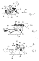
- FIG. 1 shows a schematic representation of a side view of a latch closure 2 according to the prior art with a lock carrier 4 and a lock stock 6.
- a closure pawl 10 is pivotally held in the lock stock 6 by means of an eccentric pin 8.
- the pawl closure 2 is moved in one or the other direction by means of a slide rod 12 (or also called cam rod).
- a slide rod 12 or also called cam rod.
- the lock carrier 4 is clamped to a rail foot 18 of the floor rail 14.
- the slide rod 12 is slidably guided.
- the slide rod 12 is in both directions of an arrow 20 for adjusting both switch blades 16 and the associated locking pawl 10th used.
- the closure bearing 6 is designed so that it is on the one hand attached to the switch blade 16 and on the other hand, the closure pawl 10 carries pivotable. As torsion protection, the front part of the closure bearing 6 rests on the closure carrier 4 over the entire width of the closure bearing 6. If now the position of the closure pawl 10 is adjusted relative to the closure bearing 6 by turning the eccentric bolt 8, the position of the switch blade 16 secured to the closure bearing 6 with the screw 21 is thus also affected relative to the rail 14.
- first variant of an inventive latch closure 22 is a relative to the FIG. 1 modified closure bearing 24 is used, which has a displaceable plate 26 in the upper part.
- the displaceability of the displaceable plate 26 arranged in the head region is achieved by elongated holes 28, which are formed in the closure bearing 24.
- the slidable plate 26 is then fastened by means of fixing screws 30 engaging in the elongated holes 28.
- a set screw 32 which is arranged on the side facing away from the switch tongue 16 in the closure bearing 24, so to speak on the rear side, acts as a support.
- the closure pawl 10 is held in this embodiment simplified with a round bolt 34.
- FIG. 3 shown second variant of an inventive latch closure 36 is compared to the Figures 1 and 2 modified lock bearing 38 used.
- a head plate of the closure bearing is now provided (in the sense of a hat-shaped), wherein the guidance and displaceability of the plate 40 is achieved by means of slots 42 provided in the shaped plate.
- Fixsetzschrauben 44 are also provided here.
- the fine adjustment of the shaped sheet 40 in one Displacement direction 46 is achieved by means of at least one eccentric disc 48, which is rotatable by means of the round bolt 34.
Landscapes
- Engineering & Computer Science (AREA)
- Mechanical Engineering (AREA)
- Seats For Vehicles (AREA)
- Lock And Its Accessories (AREA)
Abstract
Description
- Die vorliegende Erfindung betrifft einen Klinkenverschluss mit einer an einem Verschlusslager verschwenkbar befestigten Verschlussklinke und einer Aufnahmevorrichtung zur Verbindung einer Weichenzunge mit dem Verschlusslager.
- Zur Umstellung von Weichen ist eine Vielzahl unterschiedlicher Verstellvorrichtungen bekannt. Häufig werden Klammerspitzen- oder Klinkenverschlüsse eingesetzt. Letztgenannter Klinkenverschluss ist aus der europäischen Patentanmeldung
EP 0 624 508 A1 bekannt. - Die Klinke eines Klinkenverschluss ist verschwenkbar an einem Verschlusslager gehalten. An dem Verschlusslager wird weiter direkt oder über ein Zwischenbauteil die Weichenzunge befestigt, zu deren Verstellung und Verriegelung der Klinkenverschluss eingesetzt wird. Der Klinkenverschluss hat somit die Aufgabe die an einer Stockschiene anliegende Weichenzunge sowie die abliegende Weichenzunge in einer geometrisch exakt definierten Position festzuhalten und mechanisch zu verriegeln. Die Art der mechanischen Verriegelung erfolgt mit Vorteil formschlüssig. Aufgrund der Sicherheitsrelevanz der beschriebenen Funktionalität bestehen an die Herstellung und die Wartung von Weichen erhöhte Ansprüche, sodass es im Besonderen eine Aufgabe der Konstruktion ist, den Weichenverschluss möglichst einfach und sicher aufzubauen. Ebenso liegt derselbe Massstab an der Fertigung an, die die erforderlichen Teile des Klinkenverschlusses fehlerfrei bereitzustellen hat.
- Die Verschlussklinke - oder einfach Klinke genannt - wird in dem Verschlusslager mittels eines Exzenterbolzens schwenkbar gehalten. Mittels des Exzenterbolzens kann die Position der Verschlussklinke in einer Richtung, die senkrecht zur Ausdehnung der Stockschiene verläuft, verschoben werden. Diese Verschiebung soll das korrekte Anliegen der Weichenzunge an der Stockschiene herbeiführen. Nachteilig an der Exzenterlösung ist es jedoch, dass der Einstellbereich relativ klein ist und dass sich der relative Abstand der am Fusse des Verschlusslagers vorgesehenen Verdrehsicherung zum an der Stockschiene montierten Verschlussträger ändert. Zudem wird durch die Verstellung der Position der Verschlussklinke mit dem Exzenterbolzen auch der Drehpunkt der Klinkenlagerung entsprechend mitverschoben. Im Feld ist es daher die Regel so, dass jede Weiche mittels der Bevorratung verschiedener Verschlusslager und Verschlussklinken im Rahmen der jeweiligen Verstellbarkeit individuell anzupassen sind, was nicht nur einen hohen Aufwand der Bewirtschaftung dieser Vielzahl von Bauteilen bedingt, sondern eben auch in der Konstruktion und der Fertigung immer wieder zu vergleichsweise kostspieligen Kleinstserien führt.
- Der vorliegenden Erfindung liegt daher die Aufgabe zugrunde, einen einfach aufgebauten und funktionssicheren Klinkenverschluss anzugeben, bei dem die Verschlussklinke auch dann ortfest gehalten ist, wenn aufgrund der Einbausituation eine Anpassung der Position der Weichenzunge relativ zum Verschlusslager erforderlich ist.
- Diese Aufgabe wird erfindungsgemäss durch einen Klinkenverschluss mit einer an einem Verschlusslager verschwenkbar befestigten Verschlussklinke und einer Aufnahmevorrichtung zur Verbindung einer Weichenzunge mit dem Verschlusslager gelöst, wobei die Aufnahmevorrichtung im Kopfbereich des Verschlusslagers verschiebbar angeordnet ist.
- Auf diese Weise wird ein Klinkenverschluss erzielt, bei dem die Verschlussklinke auch dann ortfest gehalten ist, wenn aufgrund der Einbausituation die Position der Weichenzunge relativ zum Verschlusslager angepasst werden muss. Somit ergibt sich eine Einstellbarkeit des Klinkenverschluss örtlich zwischen der eigentlichen Zungenbefestigung und dem Verschlusslager. Auf diese Weise sind nur noch ein Verschlusslager-Typ und ein Verschlussklinken-Typ für alle derzeit meist gebräuchlichen Schienenprofile zu bevorraten.
- In einer konstruktiv vergleichsweise einfachen Lösungsvariante ist es vorgesehen, dass die Aufnahmevorrichtung oberhalb der Verschlussklinke liegend verschiebbar angeordnet ist. Somit bleibt auch der Raum im Bereich der Verschlussklinke und darunter von dieser Anpassung unberührt und führt zu einem einfach ausgestaltbaren Verschlusslager.
- Im Rahmen einer ersten besonders bevorzugten Ausführungsvariante der vorliegenden Erfindung ist es vorgesehen, dass die Aufnahmevorrichtung eine im Kopfbereich geführte verschiebbare Platte umfasst, wobei die Führung mittels in im Verschlusslager vorgesehene Langlöcher eingreifende Festsetzschrauben erzielt ist. Mit dem Lösen der Festsetzschrauben ist die Platte, an der die Weichenzunge befestigt ist, somit verstellbar, ohne dass an der Lage der Verschlussklinke eine Veränderung eintreten würde. In weiter zweckmässiger Weise kann dann das Verschieben der Platte mittels einer Stellschraube unterstützt sein, die auf der von der Weichenzunge abgewendete Seite im Verschlusslager angeordnet ist.
- Im Rahmen einer zweiten besonders bevorzugten Ausführungsvariante der vorliegenden Erfindung ist es vorgesehen, dass die Aufnahmevorrichtung ein den Kopfbereich des Verschlusslagers umfassendes Formblech umfasst, wobei die Führung des Formblechs mittels in im Formblech vorgesehene Langlöcher eingreifende Festsetzschrauben erzielt ist. Dabei kann hier in weiter zweckmässiger Weise die Feineinstellung des Formblechs in der Verschieberichtung mittels mindestens einer Exzenterscheibe erzielt sein. Diese Exzenterscheibe kann vorteilhaft auf der Achse des Rundbolzen, der zur verschwenkbaren Lagerung der Klinke dient, vorgesehen sein. Weitere vorteilhafte Ausgestaltungen sind in den übrigen Unteransprüchen ausgeführt.
- Vorteilhafte Ausgestaltungen der vorliegenden Erfindung werden anhand einer Zeichnung näher erläutert. Dabei zeigen:
- Figur 1
- in schematischer Darstellung eine seitliche Ansicht eines Klinkenverschlusses mit Verschlussträger und Verschlusslager gemäss dem Stand der Technik;
- Figur 2
- in schematischer Darstellung eine erste erfindungsgemässe Variante des Klinkenverschlusses mit verschiebbarer Platte; und
- Figur 3
- in schematischer Darstellung eine zweite erfindungsgemässe Variante des Klinkenverschlusses mit verschiebbarem Formblech.
- Die
Figur 1 zeigt in schematischer Darstellung eine seitliche Ansicht eines Klinkenverschlusses 2 gemäss dem Stand der Technik mit einem Verschlussträger 4 und einem Verschlusslager 6. In dem Verschlusslager 6 ist mittels eines Exzenterbolzens 8 eine Verschlussklinke 10 verschwenkbar gehalten. Der Klinkenverschluss 2 wird mittels einer Schieberstange 12 (oder auch Nockenstange genannt) in die eine oder andere Richtung bewegt. Bezüglich der Ausgestaltung eines Klinkenverschlusses wird auf die europäische PatentanmeldungEP 0 624 508 A1 verwiesen, die hiermit als komplett eingeführt gilt. In der gezeigten Darstellung ist eine an einer Stockschiene 14 anliegende Weichenzunge 16 ersichtlich. - Wie in der
Figur 1 gezeigt, wird der Verschlussträger 4 an einem Schienenfuss 18 der Stockschiene 14 verspannt. Im Verschlussträger 4 wird die Schieberstange 12 gleitend aufliegend geführt. Die Schieberstange 12 wird dabei in beide Richtungen eines Pfeils 20 zur Verstellung beider Weichenzungen 16 und der zugehörigen Verschlussklinke 10 verwendet. Das Verschlusslager 6 ist dabei so ausgeführt, dass es einerseits an der Weichenzunge 16 befestigt ist und andererseits die Verschlussklinke 10 verschwenkbar trägt. Als Verdrehschutz liegt der vordere Teil des Verschlusslagers 6 am Verschlussträger 4 über die gesamte Breite des Verschlusslagers 6 auf. Wird nun die Position der Verschlussklinke 10 durch Drehen des Exzenterbolzens 8 relativ zum Verschlusslager 6 verstellt, so wird damit auch die Lage der mit der Schraube 21 am Verschlusslager 6 befestigten Weichenzunge 16 relativ zur Stockschiene 14 tangiert. - Bei der in
Figur 2 gezeigten ersten Variante eines erfindungsgemässen Klinkenverschlusses 22 wird ein gegenüber derFigur 1 modifiziertes Verschlusslager 24 eingesetzt, das im oberen Teil eine verschiebbare Platte 26 aufweist. Die Verschiebbarkeit der im Kopfbereich angeordneten verschiebbaren Platte 26 wird dabei durch Langlöcher 28 erzielt, die im Verschlusslager 24 eingeformt sind. Die verschiebbare Platte 26 wird dann mittels in die Langlöcher 28 eingreifende Festsetzschrauben 30 befestigt. Zum Verschieben und zur genauen Einstellung der verschiebbaren Platte 26 wirkt unterstützend eine Stellschraube 32, die auf der von der Weichenzunge 16 abgewendeten Seite im Verschlusslager 24 - sozusagen auf der Rückseite - angeordnet ist. Die Verschlussklinke 10 wird bei dieser Ausführungsform vereinfacht mit einem Rundbolzen 34 gehalten. - Bei der in
Figur 3 gezeigten zweiten Variante eines erfindungsgemässen Klinkenverschlusses 36 wird ein gegenüber denFiguren 1 und 2 modifiziertes Verschlusslager 38 eingesetzt. Für die Aufnahme der Weichenzunge 16 ist nun ein den Kopfbereich des Verschlusslagers umfassendes (im Sinne von hutartig) Formblech 40 vorgesehen, wobei die Führung und Verschiebbarkeit des Formblechs 40 mittels im Formblech vorgesehener Langlöcher 42 erzielt ist. Zum Festsetzen des Formblechs 40 sind auch hier entsprechende Festsetzschrauben 44 vorgesehen. Die Feineinstellung des Formblechs 40 in einer Verschieberichtung 46 wird mittels mindestens einer Exzenterscheibe 48 erzielt, die mittels des Rundbolzens 34 verdrehbar ist.
Claims (6)
- Klinkenverschluss (22, 36) mit einer an einem Verschlusslager (24, 38) verschwenkbar befestigten Verschlussklinke (10) und einer Aufnahmevorrichtung zur Verbindung einer Weichenzunge (16) mit dem Verschlusslager (24, 38), wobei die Aufnahmevorrichtung (21, 26, 40) im Kopfbereich des Verschlusslagers (24, 38) verschiebbar angeordnet ist.
- Klinkenverschluss (22, 36) nach Anspruch 1,
dadurch gekennzeichnet, dass
die Aufnahmevorrichtung (21, 26, 40) oberhalb der Verschlussklinke (10) liegend verschiebbar angeordnet ist. - Klinkenverschluss (22) nach Anspruch 1 oder 2,
dadurch gekennzeichnet, dass
die Aufnahmevorrichtung eine im Kopfbereich geführte verschiebbare Platte (26) umfasst, wobei die Führung mittels in im Verschlusslager (24) vorgesehene Langlöcher (28) eingreifende Festsetzschrauben (30) erzielt ist. - Klinkenverschluss (22) nach Anspruch 3,
dadurch gekennzeichnet, dass
das Verschieben der Platte (26) mittels einer Stellschraube (32) unterstützt wird, die auf der von der Weichenzunge (16) abgewendete Seite im Verschlusslager (24) angeordnet ist. - Klinkenverschluss (36) nach Anspruch 1 oder 2,
dadurch gekennzeichnet, dass
die Aufnahmevorrichtung ein den Kopfbereich des Verschlusslagers (38) umfassendes Formblech (40) umfasst,
wobei die Führung des Formblechs (40) mittels in im Formblech (40) vorgesehene Langlöcher (42) eingreifende Festsetzschrauben (44) erzielt ist. - Klinkenverschluss (36) nach Anspruch 5,
dadurch gekennzeichnet, dass
die Feineinstellung des Formblechs (40) in der Verschieberichtung mittels mindestens einer Exzenterscheibe (48) erzielt ist.
Priority Applications (2)
| Application Number | Priority Date | Filing Date | Title |
|---|---|---|---|
| EP12182767.9A EP2703249B1 (de) | 2012-09-03 | 2012-09-03 | Klinkenverschluss mit einstellbarem Verschlusslager |
| PL12182767T PL2703249T3 (pl) | 2012-09-03 | 2012-09-03 | Zamknięcie zapadkowe z regulowanym łożyskiem zamknięcia |
Applications Claiming Priority (1)
| Application Number | Priority Date | Filing Date | Title |
|---|---|---|---|
| EP12182767.9A EP2703249B1 (de) | 2012-09-03 | 2012-09-03 | Klinkenverschluss mit einstellbarem Verschlusslager |
Publications (2)
| Publication Number | Publication Date |
|---|---|
| EP2703249A1 true EP2703249A1 (de) | 2014-03-05 |
| EP2703249B1 EP2703249B1 (de) | 2017-04-26 |
Family
ID=47216027
Family Applications (1)
| Application Number | Title | Priority Date | Filing Date |
|---|---|---|---|
| EP12182767.9A Active EP2703249B1 (de) | 2012-09-03 | 2012-09-03 | Klinkenverschluss mit einstellbarem Verschlusslager |
Country Status (2)
| Country | Link |
|---|---|
| EP (1) | EP2703249B1 (de) |
| PL (1) | PL2703249T3 (de) |
Citations (5)
| Publication number | Priority date | Publication date | Assignee | Title |
|---|---|---|---|---|
| EP0624508A1 (de) | 1993-05-10 | 1994-11-17 | Siemens Integra Verkehrstechnik Ag | Klinkenverschluss für Eisenbahnweichen |
| EP1078839A1 (de) * | 1999-08-24 | 2001-02-28 | CARL DAN. PEDDINGHAUS GMBH & CO. KG | Verspannungseinrichtung zwischen einer Zungenschiene und dem zugehörigen Zungenkloben |
| EP2236384A2 (de) * | 2009-03-30 | 2010-10-06 | CDP Bharat Forge GmbH | Verschlusskomponente für Stellzungen-Verschlussvorrichtung, Stellzungen-Verschlussvorrichtung und Weiche mit Stellzungen-Verschlussvorrichtung |
| EP2243681A2 (de) * | 2009-04-22 | 2010-10-27 | Schwihag Ag | Umstellvorrichtung in Eisenbahnweichen |
| EP2479080A2 (de) * | 2011-01-19 | 2012-07-25 | Siemens Schweiz AG | Klinkenverschluss mit Verschlussklammerschraube |
-
2012
- 2012-09-03 PL PL12182767T patent/PL2703249T3/pl unknown
- 2012-09-03 EP EP12182767.9A patent/EP2703249B1/de active Active
Patent Citations (5)
| Publication number | Priority date | Publication date | Assignee | Title |
|---|---|---|---|---|
| EP0624508A1 (de) | 1993-05-10 | 1994-11-17 | Siemens Integra Verkehrstechnik Ag | Klinkenverschluss für Eisenbahnweichen |
| EP1078839A1 (de) * | 1999-08-24 | 2001-02-28 | CARL DAN. PEDDINGHAUS GMBH & CO. KG | Verspannungseinrichtung zwischen einer Zungenschiene und dem zugehörigen Zungenkloben |
| EP2236384A2 (de) * | 2009-03-30 | 2010-10-06 | CDP Bharat Forge GmbH | Verschlusskomponente für Stellzungen-Verschlussvorrichtung, Stellzungen-Verschlussvorrichtung und Weiche mit Stellzungen-Verschlussvorrichtung |
| EP2243681A2 (de) * | 2009-04-22 | 2010-10-27 | Schwihag Ag | Umstellvorrichtung in Eisenbahnweichen |
| EP2479080A2 (de) * | 2011-01-19 | 2012-07-25 | Siemens Schweiz AG | Klinkenverschluss mit Verschlussklammerschraube |
Also Published As
| Publication number | Publication date |
|---|---|
| PL2703249T3 (pl) | 2017-10-31 |
| EP2703249B1 (de) | 2017-04-26 |
Similar Documents
| Publication | Publication Date | Title |
|---|---|---|
| EP2651263B1 (de) | Schubladenausziehführung | |
| EP2222202B1 (de) | Schubkasten mit Frontverstellung | |
| EP2959802B1 (de) | Vorrichtung zur anbringung einer führungseinheit an einem möbelteil | |
| EP2714568B1 (de) | Variierbare kabinentür-schachttür-kupplung | |
| EP3832062B1 (de) | Antriebseinheit für eine schiebetür | |
| EP2478154A1 (de) | System zum befestigen einer schiene und befestigung einer schiene | |
| WO2014076106A1 (de) | Türkontaktschalter, insbesondere für schaltschränke | |
| EP2180121B1 (de) | Vorrichtung zur Festlegung der Lage einer Klappe | |
| EP3253640B1 (de) | Weichenverstellmechanismus mit einem zwischen den beiden stockschienen angeordneten verschluss | |
| EP2672042A2 (de) | Führungsschienenanordnung | |
| EP2037027B1 (de) | Fadenführer für Flachstrickmaschinen | |
| AT507493B1 (de) | Laufrolle für einen schiebeflügel | |
| EP2336468B1 (de) | Beschlaggarnitur für zwei Schiebetürflügel | |
| DE102013100922B4 (de) | Laufteil zum Führen eines Möbelteils in einer Führungsrichtung über eine Führungsschiene und Möbelbeschlag | |
| EP2678504B1 (de) | Schiebetür | |
| EP2703249B1 (de) | Klinkenverschluss mit einstellbarem Verschlusslager | |
| EP3276761B1 (de) | Befestigungsvorrichtung für ein in einem gehäuse befindliches elektrisches bauteil | |
| EP2582000A1 (de) | Gehäuse eines elektrischen oder elektronischen Gerätes | |
| EP3118404A1 (de) | Rollenband, insbesondere für kunststofftüren und kunststofffenster | |
| EP2684758B1 (de) | Klinkenverschluss zum sicheren Festhalten einer abliegenden Weichenzunge | |
| EP1762454B1 (de) | Vorrichtung in einem Weichenstellsystem zum mechanischen Verriegeln einer Weichenzunge | |
| EP3212483B1 (de) | Einrichtung zur vertikalen einstellung einer schienenfahrzeugtür | |
| DE20214907U1 (de) | Vorrichtung zur regulierbaren Befestigung von Schiebetüren an einem Möbel | |
| EP3156573B1 (de) | Beschlaganordnung | |
| DE102013218354B4 (de) | Spannvorrichtung einer Kette |
Legal Events
| Date | Code | Title | Description |
|---|---|---|---|
| AK | Designated contracting states |
Kind code of ref document: A1 Designated state(s): AL AT BE BG CH CY CZ DE DK EE ES FI FR GB GR HR HU IE IS IT LI LT LU LV MC MK MT NL NO PL PT RO RS SE SI SK SM TR |
|
| AX | Request for extension of the european patent |
Extension state: BA ME |
|
| PUAI | Public reference made under article 153(3) epc to a published international application that has entered the european phase |
Free format text: ORIGINAL CODE: 0009012 |
|
| 17P | Request for examination filed |
Effective date: 20140902 |
|
| RBV | Designated contracting states (corrected) |
Designated state(s): AL AT BE BG CH CY CZ DE DK EE ES FI FR GB GR HR HU IE IS IT LI LT LU LV MC MK MT NL NO PL PT RO RS SE SI SK SM TR |
|
| 17Q | First examination report despatched |
Effective date: 20151022 |
|
| GRAP | Despatch of communication of intention to grant a patent |
Free format text: ORIGINAL CODE: EPIDOSNIGR1 |
|
| STAA | Information on the status of an ep patent application or granted ep patent |
Free format text: STATUS: GRANT OF PATENT IS INTENDED |
|
| INTG | Intention to grant announced |
Effective date: 20161201 |
|
| GRAS | Grant fee paid |
Free format text: ORIGINAL CODE: EPIDOSNIGR3 |
|
| GRAA | (expected) grant |
Free format text: ORIGINAL CODE: 0009210 |
|
| STAA | Information on the status of an ep patent application or granted ep patent |
Free format text: STATUS: THE PATENT HAS BEEN GRANTED |
|
| AK | Designated contracting states |
Kind code of ref document: B1 Designated state(s): AL AT BE BG CH CY CZ DE DK EE ES FI FR GB GR HR HU IE IS IT LI LT LU LV MC MK MT NL NO PL PT RO RS SE SI SK SM TR |
|
| REG | Reference to a national code |
Ref country code: GB Ref legal event code: FG4D Free format text: NOT ENGLISH |
|
| REG | Reference to a national code |
Ref country code: CH Ref legal event code: EP Ref country code: CH Ref legal event code: NV Representative=s name: SIEMENS SCHWEIZ AG, CH |
|
| REG | Reference to a national code |
Ref country code: AT Ref legal event code: REF Ref document number: 887608 Country of ref document: AT Kind code of ref document: T Effective date: 20170515 |
|
| REG | Reference to a national code |
Ref country code: IE Ref legal event code: FG4D Free format text: LANGUAGE OF EP DOCUMENT: GERMAN |
|
| REG | Reference to a national code |
Ref country code: DE Ref legal event code: R096 Ref document number: 502012010152 Country of ref document: DE |
|
| REG | Reference to a national code |
Ref country code: NL Ref legal event code: FP |
|
| REG | Reference to a national code |
Ref country code: NO Ref legal event code: T2 Effective date: 20170426 |
|
| REG | Reference to a national code |
Ref country code: LT Ref legal event code: MG4D |
|
| PG25 | Lapsed in a contracting state [announced via postgrant information from national office to epo] |
Ref country code: FI Free format text: LAPSE BECAUSE OF FAILURE TO SUBMIT A TRANSLATION OF THE DESCRIPTION OR TO PAY THE FEE WITHIN THE PRESCRIBED TIME-LIMIT Effective date: 20170426 Ref country code: HR Free format text: LAPSE BECAUSE OF FAILURE TO SUBMIT A TRANSLATION OF THE DESCRIPTION OR TO PAY THE FEE WITHIN THE PRESCRIBED TIME-LIMIT Effective date: 20170426 Ref country code: LT Free format text: LAPSE BECAUSE OF FAILURE TO SUBMIT A TRANSLATION OF THE DESCRIPTION OR TO PAY THE FEE WITHIN THE PRESCRIBED TIME-LIMIT Effective date: 20170426 Ref country code: GR Free format text: LAPSE BECAUSE OF FAILURE TO SUBMIT A TRANSLATION OF THE DESCRIPTION OR TO PAY THE FEE WITHIN THE PRESCRIBED TIME-LIMIT Effective date: 20170727 Ref country code: ES Free format text: LAPSE BECAUSE OF FAILURE TO SUBMIT A TRANSLATION OF THE DESCRIPTION OR TO PAY THE FEE WITHIN THE PRESCRIBED TIME-LIMIT Effective date: 20170426 |
|
| PG25 | Lapsed in a contracting state [announced via postgrant information from national office to epo] |
Ref country code: RS Free format text: LAPSE BECAUSE OF FAILURE TO SUBMIT A TRANSLATION OF THE DESCRIPTION OR TO PAY THE FEE WITHIN THE PRESCRIBED TIME-LIMIT Effective date: 20170426 Ref country code: BG Free format text: LAPSE BECAUSE OF FAILURE TO SUBMIT A TRANSLATION OF THE DESCRIPTION OR TO PAY THE FEE WITHIN THE PRESCRIBED TIME-LIMIT Effective date: 20170726 Ref country code: IS Free format text: LAPSE BECAUSE OF FAILURE TO SUBMIT A TRANSLATION OF THE DESCRIPTION OR TO PAY THE FEE WITHIN THE PRESCRIBED TIME-LIMIT Effective date: 20170826 Ref country code: LV Free format text: LAPSE BECAUSE OF FAILURE TO SUBMIT A TRANSLATION OF THE DESCRIPTION OR TO PAY THE FEE WITHIN THE PRESCRIBED TIME-LIMIT Effective date: 20170426 Ref country code: SE Free format text: LAPSE BECAUSE OF FAILURE TO SUBMIT A TRANSLATION OF THE DESCRIPTION OR TO PAY THE FEE WITHIN THE PRESCRIBED TIME-LIMIT Effective date: 20170426 |
|
| REG | Reference to a national code |
Ref country code: DE Ref legal event code: R097 Ref document number: 502012010152 Country of ref document: DE |
|
| PG25 | Lapsed in a contracting state [announced via postgrant information from national office to epo] |
Ref country code: EE Free format text: LAPSE BECAUSE OF FAILURE TO SUBMIT A TRANSLATION OF THE DESCRIPTION OR TO PAY THE FEE WITHIN THE PRESCRIBED TIME-LIMIT Effective date: 20170426 Ref country code: CZ Free format text: LAPSE BECAUSE OF FAILURE TO SUBMIT A TRANSLATION OF THE DESCRIPTION OR TO PAY THE FEE WITHIN THE PRESCRIBED TIME-LIMIT Effective date: 20170426 Ref country code: DK Free format text: LAPSE BECAUSE OF FAILURE TO SUBMIT A TRANSLATION OF THE DESCRIPTION OR TO PAY THE FEE WITHIN THE PRESCRIBED TIME-LIMIT Effective date: 20170426 Ref country code: SK Free format text: LAPSE BECAUSE OF FAILURE TO SUBMIT A TRANSLATION OF THE DESCRIPTION OR TO PAY THE FEE WITHIN THE PRESCRIBED TIME-LIMIT Effective date: 20170426 Ref country code: RO Free format text: LAPSE BECAUSE OF FAILURE TO SUBMIT A TRANSLATION OF THE DESCRIPTION OR TO PAY THE FEE WITHIN THE PRESCRIBED TIME-LIMIT Effective date: 20170426 |
|
| PG25 | Lapsed in a contracting state [announced via postgrant information from national office to epo] |
Ref country code: SM Free format text: LAPSE BECAUSE OF FAILURE TO SUBMIT A TRANSLATION OF THE DESCRIPTION OR TO PAY THE FEE WITHIN THE PRESCRIBED TIME-LIMIT Effective date: 20170426 Ref country code: IT Free format text: LAPSE BECAUSE OF FAILURE TO SUBMIT A TRANSLATION OF THE DESCRIPTION OR TO PAY THE FEE WITHIN THE PRESCRIBED TIME-LIMIT Effective date: 20170426 |
|
| PLBE | No opposition filed within time limit |
Free format text: ORIGINAL CODE: 0009261 |
|
| STAA | Information on the status of an ep patent application or granted ep patent |
Free format text: STATUS: NO OPPOSITION FILED WITHIN TIME LIMIT |
|
| 26N | No opposition filed |
Effective date: 20180129 |
|
| GBPC | Gb: european patent ceased through non-payment of renewal fee |
Effective date: 20170903 |
|
| PG25 | Lapsed in a contracting state [announced via postgrant information from national office to epo] |
Ref country code: SI Free format text: LAPSE BECAUSE OF FAILURE TO SUBMIT A TRANSLATION OF THE DESCRIPTION OR TO PAY THE FEE WITHIN THE PRESCRIBED TIME-LIMIT Effective date: 20170426 Ref country code: MC Free format text: LAPSE BECAUSE OF FAILURE TO SUBMIT A TRANSLATION OF THE DESCRIPTION OR TO PAY THE FEE WITHIN THE PRESCRIBED TIME-LIMIT Effective date: 20170426 |
|
| REG | Reference to a national code |
Ref country code: IE Ref legal event code: MM4A |
|
| REG | Reference to a national code |
Ref country code: BE Ref legal event code: MM Effective date: 20170930 |
|
| PG25 | Lapsed in a contracting state [announced via postgrant information from national office to epo] |
Ref country code: LU Free format text: LAPSE BECAUSE OF NON-PAYMENT OF DUE FEES Effective date: 20170903 |
|
| REG | Reference to a national code |
Ref country code: FR Ref legal event code: ST Effective date: 20180531 |
|
| PG25 | Lapsed in a contracting state [announced via postgrant information from national office to epo] |
Ref country code: IE Free format text: LAPSE BECAUSE OF NON-PAYMENT OF DUE FEES Effective date: 20170903 Ref country code: GB Free format text: LAPSE BECAUSE OF NON-PAYMENT OF DUE FEES Effective date: 20170903 |
|
| PG25 | Lapsed in a contracting state [announced via postgrant information from national office to epo] |
Ref country code: FR Free format text: LAPSE BECAUSE OF NON-PAYMENT OF DUE FEES Effective date: 20171002 Ref country code: BE Free format text: LAPSE BECAUSE OF NON-PAYMENT OF DUE FEES Effective date: 20170930 |
|
| PG25 | Lapsed in a contracting state [announced via postgrant information from national office to epo] |
Ref country code: MT Free format text: LAPSE BECAUSE OF FAILURE TO SUBMIT A TRANSLATION OF THE DESCRIPTION OR TO PAY THE FEE WITHIN THE PRESCRIBED TIME-LIMIT Effective date: 20170426 |
|
| REG | Reference to a national code |
Ref country code: CH Ref legal event code: PUE Owner name: SIEMENS MOBILITY AG, CH Free format text: FORMER OWNER: SIEMENS SCHWEIZ AG, CH |
|
| REG | Reference to a national code |
Ref country code: DE Ref legal event code: R082 Ref document number: 502012010152 Country of ref document: DE Representative=s name: MAIER, DANIEL OLIVER, DIPL.-ING. UNIV., DE Ref country code: DE Ref legal event code: R081 Ref document number: 502012010152 Country of ref document: DE Owner name: SIEMENS MOBILITY AG, CH Free format text: FORMER OWNER: SIEMENS SCHWEIZ AG, ZUERICH, CH |
|
| PG25 | Lapsed in a contracting state [announced via postgrant information from national office to epo] |
Ref country code: HU Free format text: LAPSE BECAUSE OF FAILURE TO SUBMIT A TRANSLATION OF THE DESCRIPTION OR TO PAY THE FEE WITHIN THE PRESCRIBED TIME-LIMIT; INVALID AB INITIO Effective date: 20120903 |
|
| REG | Reference to a national code |
Ref country code: AT Ref legal event code: PC Ref document number: 887608 Country of ref document: AT Kind code of ref document: T Owner name: SIEMENS MOBILITY AG, CH Effective date: 20190612 |
|
| PG25 | Lapsed in a contracting state [announced via postgrant information from national office to epo] |
Ref country code: CY Free format text: LAPSE BECAUSE OF NON-PAYMENT OF DUE FEES Effective date: 20170426 |
|
| REG | Reference to a national code |
Ref country code: NL Ref legal event code: PD Owner name: SIEMENS MOBILITY AG; CH Free format text: DETAILS ASSIGNMENT: CHANGE OF OWNER(S), ASSIGNMENT; FORMER OWNER NAME: SIEMENS SCHWEIZ AG Effective date: 20191031 |
|
| REG | Reference to a national code |
Ref country code: NO Ref legal event code: CHAD Owner name: SIEMENS MOBILITY AG, CH |
|
| PG25 | Lapsed in a contracting state [announced via postgrant information from national office to epo] |
Ref country code: MK Free format text: LAPSE BECAUSE OF FAILURE TO SUBMIT A TRANSLATION OF THE DESCRIPTION OR TO PAY THE FEE WITHIN THE PRESCRIBED TIME-LIMIT Effective date: 20170426 |
|
| PG25 | Lapsed in a contracting state [announced via postgrant information from national office to epo] |
Ref country code: TR Free format text: LAPSE BECAUSE OF FAILURE TO SUBMIT A TRANSLATION OF THE DESCRIPTION OR TO PAY THE FEE WITHIN THE PRESCRIBED TIME-LIMIT Effective date: 20170426 |
|
| PG25 | Lapsed in a contracting state [announced via postgrant information from national office to epo] |
Ref country code: PT Free format text: LAPSE BECAUSE OF FAILURE TO SUBMIT A TRANSLATION OF THE DESCRIPTION OR TO PAY THE FEE WITHIN THE PRESCRIBED TIME-LIMIT Effective date: 20170426 |
|
| PG25 | Lapsed in a contracting state [announced via postgrant information from national office to epo] |
Ref country code: AL Free format text: LAPSE BECAUSE OF FAILURE TO SUBMIT A TRANSLATION OF THE DESCRIPTION OR TO PAY THE FEE WITHIN THE PRESCRIBED TIME-LIMIT Effective date: 20170426 |
|
| PGFP | Annual fee paid to national office [announced via postgrant information from national office to epo] |
Ref country code: NO Payment date: 20250910 Year of fee payment: 14 |
|
| PGFP | Annual fee paid to national office [announced via postgrant information from national office to epo] |
Ref country code: NL Payment date: 20250902 Year of fee payment: 14 Ref country code: PL Payment date: 20250821 Year of fee payment: 14 |
|
| PGFP | Annual fee paid to national office [announced via postgrant information from national office to epo] |
Ref country code: AT Payment date: 20250818 Year of fee payment: 14 |
|
| REG | Reference to a national code |
Ref country code: CH Ref legal event code: U11 Free format text: ST27 STATUS EVENT CODE: U-0-0-U10-U11 (AS PROVIDED BY THE NATIONAL OFFICE) Effective date: 20251210 |
|
| PGFP | Annual fee paid to national office [announced via postgrant information from national office to epo] |
Ref country code: DE Payment date: 20251120 Year of fee payment: 14 |
|
| PGFP | Annual fee paid to national office [announced via postgrant information from national office to epo] |
Ref country code: CH Payment date: 20251210 Year of fee payment: 14 |