EP2703216A2 - Commercial vehicle superstructure with load securing for double decker operation - Google Patents
Commercial vehicle superstructure with load securing for double decker operation Download PDFInfo
- Publication number
- EP2703216A2 EP2703216A2 EP13181124.2A EP13181124A EP2703216A2 EP 2703216 A2 EP2703216 A2 EP 2703216A2 EP 13181124 A EP13181124 A EP 13181124A EP 2703216 A2 EP2703216 A2 EP 2703216A2
- Authority
- EP
- European Patent Office
- Prior art keywords
- double
- decker
- commercial vehicle
- rails
- load securing
- Prior art date
- Legal status (The legal status is an assumption and is not a legal conclusion. Google has not performed a legal analysis and makes no representation as to the accuracy of the status listed.)
- Granted
Links
- 238000010276 construction Methods 0.000 claims description 14
- 230000037431 insertion Effects 0.000 claims description 14
- 238000003780 insertion Methods 0.000 claims description 14
- 230000001012 protector Effects 0.000 abstract 2
- 238000004519 manufacturing process Methods 0.000 description 3
- 239000012792 core layer Substances 0.000 description 2
- 230000002349 favourable effect Effects 0.000 description 2
- 239000010410 layer Substances 0.000 description 2
- 229910000831 Steel Inorganic materials 0.000 description 1
- 238000006073 displacement reaction Methods 0.000 description 1
- 230000005484 gravity Effects 0.000 description 1
- 239000002184 metal Substances 0.000 description 1
- 238000009991 scouring Methods 0.000 description 1
- 239000007787 solid Substances 0.000 description 1
- 239000010959 steel Substances 0.000 description 1
Images


Classifications
-
- B—PERFORMING OPERATIONS; TRANSPORTING
- B60—VEHICLES IN GENERAL
- B60P—VEHICLES ADAPTED FOR LOAD TRANSPORTATION OR TO TRANSPORT, TO CARRY, OR TO COMPRISE SPECIAL LOADS OR OBJECTS
- B60P7/00—Securing or covering of load on vehicles
- B60P7/06—Securing of load
- B60P7/135—Securing or supporting by load bracing means
- B60P7/15—Securing or supporting by load bracing means the load bracing means comprising a movable bar
Definitions
- the invention relates to a commercial vehicle body, in particular box body of a commercial vehicle, in particular a truck, trailer and / or semitrailer, with a cargo space and at least one side wall, wherein the side wall has at least two vertically extending and the cargo space open double-decker rails.
- Commercial vehicles for transporting goods by road have suitable commercial vehicle bodies for receiving the goods.
- the commercial vehicles in question are in particular lorry trailers and / or semitrailers.
- the commercial vehicle superstructures can be, for example, tarpaulin bodies or box bodies.
- the cargo space is closed at least laterally by tarpaulins.
- Tarpaulin structures in which the lateral tarpaulins can be slid in the longitudinal direction of the utility vehicle are also referred to as curtainsider bodies.
- the cargo space of box bodies is also enclosed laterally by solid walls. These are usually designed in the form of sandwich panels and have outer cover layers and an interposed core layer, such as a foamed plastic, on.
- Box bodies which can be quickly picked up by a trailer chassis and separated again, are referred to as Konkoffer inconvenienceten and have legs, with the help of the Konkoffer excessiveten can be parked on the ground at a height that allows driving under the truck bodies by a trailer chassis for the purpose of receiving the exchangeable cargo bodies.
- the commercial vehicle superstructures can be flexibly loaded depending on the goods to be transported, these are partially equipped with so-called double-deck rails.
- These vertically extending and distributed at predetermined intervals in the longitudinal direction of the utility vehicle arranged double-decker rails serve to accommodate so-called double-decker beams at different heights.
- the double-decker beams then extend transversely of the commercial vehicle from a double-decker rail to an opposite double-decker rail on the other side wall.
- the double-deck rails are spaced according to the width or length of standard pallets, so that a standard pallet can be placed on two adjacent double-decker beams. In this way, standard pallets can be loaded on several levels one above the other to make the most efficient use of the cargo space.
- the type and attachment of the double-deck rails according to the invention is particularly in the DE EP 2 116 448 A1 why this description is also made by reference to the subject of the present description in terms of a preferred embodiment.
- the double-deck rails are usually embedded in the side walls in order to make full use of the width of the cargo space.
- the double - level rails also serve both to lock the double - decker bars in the desired height as well as the guidance of the double-decker beams when moving from one height to another height.
- load-securing rails in which load-securing means such as tension belts or the like can be fastened.
- load-securing rails When attaching the load securing rails, a compromise must be made between easy loading and cost-effective production of the commercial vehicle.
- the invention is therefore based on the object, the commercial vehicle bodies of the type mentioned above and described in more detail above and further develop that the known disadvantages can be taken into account.
- the double-deck rails are used not only for mounting the double-decker beams, but also for mounting the load securing beam.
- the load securing beams are fixed in different heights in the double-deck rails and / or lockable. In this way it is achieved that the mounting height of the load securing beam can be adapted to the mounting height of the double decker beams to achieve regardless of the mounting height of the double decker beams a simple and secure load securing the parked on the double decker beams goods.
- the load securing bar is not necessarily coupled to the simultaneous use of double-decker bars.
- the load securing beams can also be used to secure loads of goods parked on the floor of the commercial vehicle body.
- the at least one load securing beam in the double deck rails can be fixed or locked at different heights.
- two or more load securing bars can be fixed one above the other at the at least one side wall, for example in order to secure particularly heavy goods against slipping or overturning.
- the load securing beams are not only lockable in different heights, but also guided in the height adjustment in the double-decker rails.
- This guide can be achieved by a positive connection transverse to the double-deck rails, for example along and / or transverse to the commercial vehicle.
- a load securing bar extends in the assembled state of a double-decker rail to another double-deck rail of the same side wall.
- the number of load securing bars can vary as a whole.
- Several load securing bars can be arranged one above the other and or in the longitudinal direction of the utility vehicle next to each other. The same applies to the double-decker beams.
- double-level rails can in principle be all vertical rails of the sidewall of the commercial vehicle body which are open towards the loading space. Accordingly, the double-deck rails also need not necessarily be provided for receiving double-decker beams. The double-deck rails may also be provided for receiving other equipment of the commercial vehicle.
- the double-decker rails can be provided and designed to set certain load securing elements on the side wall adjustable in height. This can serve, for example, to secure the load or merely to stow away the cargo securing elements safely if these are not used. The load securing elements can thus damage neither the goods to be transported nor the commercial vehicle body.
- double-decker rails are actually provided and designed for receiving and adjusting the height of double-decker bars.
- these double-decker rails can accommodate the forces required to secure loads with the aid of the load-securing bars and / or enable safe double-deck operation of the commercial vehicle body. Therefore, for the sake of simplicity and ease of understanding, the term double-decker rail will continue to be described, without any inconvenient distinction between a double-decker rail in the narrow sense and another vertical rail open to the cargo space of at least one side wall. The term double-decker rail will therefore continue to be used, even though it may have a broader meaning according to the invention than it sometimes has in practice.
- a double-decker bar is vertically displaceably received in at least one of the double-deck rails in addition to the load securing bar and held fixed at different heights.
- a double-decker bar is vertically displaceably accommodated in each of the two double-decker rails accommodating at least one load-securing bar and can be held fixed at different heights.
- the double-deck rails have a T-slot open to the loading space.
- the groove of the double-decker rail has undercuts and is at least partially T-shaped in cross-section. It is structurally simple when the double-deck rail has the opening to the loading space narrowing ribs.
- the load-securing bar and / or at least one double-decker bar can then be held behind the ribs of the T-slot in the T-slot.
- the corresponding form-fitting preferably prevents the load-securing bar and / or the at least one double-decker bar from being pulled out of it accidentally perpendicular to the double-deck bar.
- the load securing bar and / or the at least one double-decker bar can be moved easily and reliably along a double-decker rail without accidentally disengaging from the double-decker rail
- the load securing bar and / or the at least one double-decker bar may comprise at least one push-in bar for engaging in a double-decker rail for engaging behind the undercuts or ribs of the double-decker rail.
- the double-decker rail has an insertion opening for the load-securing bar and / or the double-decker bar.
- the load-securing bar and / or the at least one double-decker beams, in particular the corresponding Schiebling be inserted into the double-decker rail and / or taken out of the double-decker rail.
- the insertion opening is provided at one end, preferably the lower end of the double-decker rail. In this case, the insertion opening can be created for the sake of simplicity that the pointing to the loading space opening of the double-decker rail in the region of the insertion opening is wider.
- a slide can then be easily brought, for example, in an undercut the undercuts of the double-decker rail position.
- the double-deck beams and the load-securing beams for insertion into the double-deck rails need not be raised excessively.
- the Schiebling has at least partially a T-shaped cross-section.
- the Schiebling engages behind the ribs of the double-deck rails, so as to counteract accidental withdrawal of the Schieblings from the double-decker rail.
- the slide can be designed in a simple manner as a slider.
- the Schiebling then slips due to its shape along the double-deck rail to the desired position, why the Schiebling can have rounded edges or the like.
- the possibly rubbing surfaces are smooth and the slide is made of a plastic.
- the friction between the Schiebling and the double-decker rail can also be reduced by the fact that the Schiebling is formed in the form of a wheel which roll when moving the Schieblings along the double-decker rail on a flank of the double-decker rail, between the groove base and the ribs in the region of the opening to the loading space can. It is particularly preferred if the axis of rotation of the wheel extends approximately perpendicular to the side wall.
- the wheel is also preferably so large that it can engage behind the undercuts of the double-decker rail.
- the slide-on may also have a roller associated with a particular flank of the double-decker rail for unwinding on that flank when the push-slide is displaced along the double-decker rail.
- a plurality of rollers per slide can be provided, which can be assigned to different flanks or ribs of the double-deck rail.
- the load-securing bar is designed to be telescopic.
- the slide can be designed to be adjustable along the load securing beam. Such adjustability can be provided longitudinally or transversely to the load securing bar.
- the double-decker rails may have recesses. These recesses may, if necessary, have uniform spacing along the double-deck rails. This achieves a uniform height grid. Alternatively or additionally, the recesses can serve a positive engagement of the load securing beams and / or the double-decker beams so that they can not accidentally slip down the double-decker rails.
- the load securing beam and / or the double-decker beam has a locking element for engaging and supporting in at least one recess of the double-decker rail.
- the engagement of the locking element in the recess can preferably lead to a positive connection in a vertical direction down.
- the locking elements of the load securing bar are adjustable from the mounting position to a positioning position.
- the load securing bar is then preferably displaceable longitudinally of the double-deck rails held in the same. It is particularly simple and reliable, when the locking elements are moved during adjustment of the mounting position in the positioning position and back perpendicular to the double-deck rails.
- the adjustment of the load securing bar along the double floor rails can be simplified if the locking elements of the load securing bar are coupled to an operating unit with which the locking elements can be moved from the mounting position to the positioning position and back. It offers itself from a constructive point of view and the ease of handling because of, to form the control unit as a hand lever.
- the locking elements and / or the operating unit is spring-loaded in the direction of the positioning position of the locking elements, it can be ensured in a simple manner that the locking elements change back into the mounting position after shifting the load securing beam and fix the load securing beam in the double-deck rails.
- the load-securing bar adjacent to at least one side wall may have a scuff guard.
- the side wall is preferably harder than the scuff plate.
- the scuff plates can be mounted easily replaceable. As favorable bead-like scuff plates and / or scouring strips made of plastic have proven.
- the basic form of the load securing bar is formed by at least two partial profiles. These are basically inexpensive to manufacture and easy to connect.
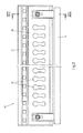
- a commercial vehicle N in the form of a semitrailer with a commercial vehicle body 1 in the form of a box body is shown.
- the commercial vehicle body 1 comprises an end wall 2, a rear wall 3, a roof 4, two side walls 5, 6 and a bottom 7.
- the side walls 5, 6, the end wall 2 and the roof 4 are designed as sandwich panels. These include outer cover layers of metal, preferably steel, between which a core layer of a foamed plastic is arranged.
- double-rail 8 inserted into the side walls 5,6 extending in the vertical direction and each have fixed predetermined distances in the horizontal direction.
- a double-decker bar 9 is mounted in each case.
- a load securing bar 10 is mounted in both double-decker rails 8. While the double deck beams 10 extend transversely of the commercial vehicle body 1, the load securing bar 10 extends in the longitudinal direction of the commercial vehicle body 1.
- the double deck beams 9 are adapted to receive the ends of two adjacent standard pallets. But it can also be provided close to each other two double-decker rails.
- adjacent double-decker beams and adjacent standard pallets can easily handle different heights to be ordered.
- the double-decker bars can be moved independently of each other in a separate double-decker rail.
- adjacent double-deck rails are alternately provided at a very small distance and a distance adapted to the dimensions of a standard pallet.
- the double-decker bars 9 are held on the opposite side wall 5,6 in similar double-decker rails 8 and that with these double-decker rails 8, a similar load securing bar 10 is connected. Both the load-securing bars 10 and the double-decker bars 9 are held in a height-displaceable manner in the same double-decker rails 8 and can be fixed one above the other at different heights in the double-decker rail 8.
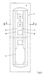
- the load securing bar 10 is shown in a plan view from the front.
- the front of the load securing bar 10 has a series of longitudinally spaced openings 11 at regular intervals in which cargo securing means such as straps or the like can be secured.
- the basic form of the load securing beam 10 is formed by two interconnected sub-profiles 12,13. Other attachments, such as an operating unit 14 in the form of a hand lever for moving the load securing bar 10 are provided in addition.
- Fig. 3 the back of the load securing bar 10 is shown.
- locking elements 16 are provided to set the load-securing bar 10 in the desired height in the double-decker rails 8. The locking elements 16 can be adjusted via the operating unit 14, and so release the load securing bar 10 for moving in the longitudinal direction of the double-decker rails 8.
- Fig. 4 and 5 are shown corresponding to the sliders 15 and the locking elements 16 formed double-decker rails 8.
- the double-deck rails 8 have a T-slot 17, which has a corresponding T-shaped cross-section. This shape of the groove 17 is provided by two ribs 18 which narrow the groove in the region of the opening 19 facing the loading space.
- the sliders 15 of the load securing beam 10 have a corresponding T-shaped cross-section, with which the slides 15 are received in the T-slots 17 of the double-decker rails 8.
- the sliders 15 can be moved along the double-deck rails 8, without the risk that the load-securing bar 10 is disengaged from the double-deck rails 8, because the sliders 15 engage behind during the sliding along the double-decker rail 8, the undercuts or ribs 18 of T-slot 17 of the double-deck rails 8. An accidental pulling out of the load securing beam 10 or sliding member 15 perpendicular to the side wall 5,6 is thus prevented.
- the double-decker rails 8 have along the groove bottom 20 recesses 21, in which the locking elements 16 of the load securing bar 10 can engage.
- the load securing bar 10 is then supported in its corresponding mounting position in the direction of gravity via the locking elements 16 and recesses 21 on the double-decker rails 8.
- the recesses 21 are arranged at constant distances from each other, so that a constant height grid is created.
- insertion openings 22 For insertion of the load securing bar 10, in the double-decker rails 8, these have at their lower ends insertion openings 22. These are essentially formed by shortened in this area ribs 18 of the T-groove 17.
- the sliders 15 of the load securing beam 10 can be inserted and then moved along the double-deck rails 8 upwards in the respective desired position.
- the sliders 15 can also be taken out of the double-decker rails 8 via the insertion openings 22, in particular pulled out, since the insertion openings 22 are wider than the parts of the sliders 15 to be inserted into the T-slot 17 in the same direction.
- the load securing bar 10 is shown in a side view.
- the operating unit 14 is arranged for adjusting the locking element 16.
- the illustrated in the extent preferred load securing bar 10 pin-shaped locking member 16 is in the illustrated mounting position against the sliding member 15 backwards.
- the Schiebling 15 in turn is facing the base body 23 to the rear, because the slide 15 engages in the T-groove 17 of the double-decker rail 8, while the locking member 16 engages in the mounting position also in the recesses 21 in the groove bottom 20 of the double-decker rails 8.
- the sliding members 15 engage behind the ribs 18 of the T-slots 17 with protrusions 24 projecting outward on both sides.
- the sliders 15 and the double-deck rails 8 are also coordinated so that the sliders 15 can be moved without great friction in the double-decker rails 8. So that this displacement does not lead to damage of the side wall 5,6 and / or the double-decker rails 8 is provided at the back of the body 23 of the load securing bar 10 top and bottom depending on a rearwardly projecting, bead-shaped scuff guard 25 which in the connected state on the side wall 5.6 and / or the double-decker rails 8 is present.
- Fig. 7 is a sectional view of the load securing bar 10 shown in the assembled position, while in the Fig. 8 the load securing bar 10 is shown in a positioning position.
- the basic form of the load securing bar 10 is composed of two partial profiles 12,13.
- the locking element 16 In the assembled position, the locking element 16 is displaced into a rear end position and is located on a stop 26 of the slide, against which the locking element 16 is pressed by the restoring force of a, in this case, the locking element 16 embracing spring 27 at.
- the locking member 16 also passes through the control unit 14, which is a Rotary axis 28 can be pivoted forward.
- the operating unit 14 presses a stop 29 of the locking member 16 forward and pushes the locking member 16 against the restoring force of the spring 27 and perpendicular to the double-decker rail 8 forward, and to the extent that the locking member 16 disengages from the recess 21 of the double-decker rail 8 ,
- the load securing bar 10 can therefore be easily moved up and down in the double-decker rails 8.
- the operator simply releases the control unit 14. Due to the restoring force of the spring 27, the load securing bar 10 or the locking element 16 returns to the assembly position. In this is given by the engagement of the locking elements in recesses 21 of the double-decker rails 8, a locking of the load securing bar 10 in the double-decker rails 8.
Abstract
Description
Die Erfindung betrifft einen Nutzfahrzeugaufbau, insbesondere Kofferaufbau eines Nutzfahrzeugs, insbesondere eines Lastkraftwagens, Anhängers und/oder Sattelaufliegers, mit einem Laderaum und wenigstens einer Seitenwand, wobei die Seitenwand wenigstens zwei vertikal verlaufende und zum Laderaum hin geöffnete Doppelstockschienen aufweist.The invention relates to a commercial vehicle body, in particular box body of a commercial vehicle, in particular a truck, trailer and / or semitrailer, with a cargo space and at least one side wall, wherein the side wall has at least two vertically extending and the cargo space open double-decker rails.
Nutzfahrzeuge zum Transport von Gütern im Straßenverkehr weisen zur Aufnahme der Güter geeignete Nutzfahrzeugaufbauten auf. Bei den in Frage kommenden Nutzfahrzeugen handelt es sich insbesondere um Lastkraftwagen Anhänger und/oder Sattelauflieger. Die Nutzfahrzeugaufbauten können dabei beispielsweise Planenaufbauten oder Kofferaufbauten sein.Commercial vehicles for transporting goods by road have suitable commercial vehicle bodies for receiving the goods. The commercial vehicles in question are in particular lorry trailers and / or semitrailers. The commercial vehicle superstructures can be, for example, tarpaulin bodies or box bodies.
Bei Planenaufbauten wird der Laderaum zumindest seitlich durch Planen verschlossen. Planenaufbauten, bei denen die seitlichen Planen in Längsrichtung des Nutzfahrzeugs aufgeschoben werden können, werden auch als Curtainsider-Aufbauten bezeichnet. Im Gegensatz zu den Planenaufbauten wird der Laderaum von Kofferaufbauten auch seitlich durch feste Wände umschlossen. Diese sind meist in Form von Sandwich-Paneelen ausgebildet und weisen äußere Decklagen und eine dazwischen angeordnete Kernschicht, etwa aus einem geschäumten Kunststoff, auf. Kofferaufbauten, die schnell von einem Anhängerchassis aufgenommen und wieder getrennt werden können, werden als Wechselkofferaufbauten bezeichnet und weisen Beine auf, mit deren Hilfe die Wechselkofferaufbauten auf dem Boden in einer Höhe abgestellt werden können, die ein Unterfahren der Wechselkofferaufbauten durch einen Anhängerchassis zum Zwecke der Aufnahme der Wechselkofferaufbauten erlaubt.In tarpaulin structures, the cargo space is closed at least laterally by tarpaulins. Tarpaulin structures in which the lateral tarpaulins can be slid in the longitudinal direction of the utility vehicle are also referred to as curtainsider bodies. In contrast to the tarpaulin superstructures, the cargo space of box bodies is also enclosed laterally by solid walls. These are usually designed in the form of sandwich panels and have outer cover layers and an interposed core layer, such as a foamed plastic, on. Box bodies, which can be quickly picked up by a trailer chassis and separated again, are referred to as Wechselkofferaufbauten and have legs, with the help of the Wechselkofferaufbauten can be parked on the ground at a height that allows driving under the truck bodies by a trailer chassis for the purpose of receiving the exchangeable cargo bodies.
Damit die Nutzfahrzeugaufbauten abhängig von den zu transportierenden Gütern flexibel beladen werden können, werden diese teilweise mit sogenannten Doppelstockschienen ausgerüstet. Diese vertikal verlaufenden und in vorbestimmten Abständen in Längsrichtung des Nutzfahrzeugs verteilt angeordneten Doppelstockschienen dienen der Aufnahme von sogenannten Doppelstockbalken in verschiedenen Höhen. Die Doppelstockbalken erstrecken sich dann quer zum Nutzfahrzeug von einer Doppelstockschiene zu einer gegenüberliegenden Doppelstockschiene an der anderen Seitenwand. Die Doppelstockschienen sind entsprechend der Breite oder Länge von Normpaletten voneinander beabstandet, so dass eine Normpalette auf zwei benachbarten Doppelstockbalken abgestellt werden kann. Auf diese Weise können Normpaletten in mehreren Etagen übereinander verladen werden, um den Laderaum möglichst effizient auszunutzen.So that the commercial vehicle superstructures can be flexibly loaded depending on the goods to be transported, these are partially equipped with so-called double-deck rails. These vertically extending and distributed at predetermined intervals in the longitudinal direction of the utility vehicle arranged double-decker rails serve to accommodate so-called double-decker beams at different heights. The double-decker beams then extend transversely of the commercial vehicle from a double-decker rail to an opposite double-decker rail on the other side wall. The double-deck rails are spaced according to the width or length of standard pallets, so that a standard pallet can be placed on two adjacent double-decker beams. In this way, standard pallets can be loaded on several levels one above the other to make the most efficient use of the cargo space.
Die Art und die Anbringung der Doppelstockschienen im Sinne der Erfindung ist insbesondere in der DE
Damit die auf den Doppelstockbalken abgestellte Ladung gegen Verrutschen gesichert werden kann, weisen einige Nutzfahrzeugaufbauten zwischen den Doppelstockschienen längs zum Nutzfahrzeugaufbau Ladungssicherungsschienen auf, in denen Ladungssicherungsmittel wie Spanngurte oder dergleichen befestigt werden können. Beim Anbringen der Ladungssicherungsschienen muss ein Kompromiss zwischen einer leichten Verladung und einer kostengünstigen Herstellung des Nutzfahrzeugs getroffen werden.In order for the cargo parked on the double-decker beams to be secured against slippage, some commercial-vehicle superstructures between the double-decker rails along the commercial vehicle superstructure have load-securing rails in which load-securing means such as tension belts or the like can be fastened. When attaching the load securing rails, a compromise must be made between easy loading and cost-effective production of the commercial vehicle.
Es kann beispielsweise zwischen zwei Doppelstockschienen jeweils nur eine einzige Ladungssicherungsschiene vorgesehen werden. Dann kann jedoch die Ladungssicherung mühsam sein, wenn die Doppelstockbalken weit oberhalb oder unterhalb der Ladungssicherungsschiene montiert werden. Wenn zwischen den Doppelstockschienen eine Reihe von Ladungssicherungsschienen auf unterschiedlichen Höhen vorgesehen werden, wie dies bei dem aus der
Der Erfindung liegt daher die Aufgabe zugrunde, die Nutzfahrzeugaufbauten der eingangs genannten und zuvor näher beschriebenen Art derart auszugestalten und weiterzubilden, dass den bekannten Nachteilen Rechnung getragen werden kann.The invention is therefore based on the object, the commercial vehicle bodies of the type mentioned above and described in more detail above and further develop that the known disadvantages can be taken into account.
Diese Aufgabe ist erfindungsgemäß bei einem Nutzfahrzeug nach dem Oberbegriff des Anspruchs 1 dadurch gelöst, dass wenigstens ein Ladungssicherungsbalken in beiden Doppelstockschienen höhenverschiebbar aufgenommen und in unterschiedlichen Höhen festlegbar gehalten ist.This object is achieved according to the invention in a commercial vehicle according to the preamble of claim 1, characterized in that at least one load-securing bar is vertically displaceable in both double-decker rails and held fixed at different heights.
Erfindungsgemäß werden also die Doppelstockschienen nicht nur zur Montage der Doppelstockbalken, sondern auch zur Montage des Ladungssicherungsbalkens genutzt. Dabei sind auch die Ladungssicherungsbalken in unterschiedlichen Höhen in den Doppelstockschienen festlegbar und/oder arretierbar. Auf diese Weise wird erreicht, dass sich die Montagehöhe des Ladungssicherungsbalkens an die Montagehöhe der Doppelstockbalken anpassen lässt, um unabhängig von der Montagehöhe der Doppelstockbalken eine einfache und sichere Ladungssicherung der auf den Doppelstockbalken abgestellten Güter zu erreichen.Thus, according to the invention, the double-deck rails are used not only for mounting the double-decker beams, but also for mounting the load securing beam. In this case, the load securing beams are fixed in different heights in the double-deck rails and / or lockable. In this way it is achieved that the mounting height of the load securing beam can be adapted to the mounting height of the double decker beams to achieve regardless of the mounting height of the double decker beams a simple and secure load securing the parked on the double decker beams goods.
Die Verwendung der Ladungssicherungsbalken ist dabei nicht zwingend an die gleichzeitige Verwendung von Doppelstockbalken gekoppelt. Die Ladungssicherungsbalken können bedarfsweise auch zur Ladungssicherung von auf dem Boden des Nutzfahrzeugaufbaus abgestellten Gütern genutzt werden. Abhängig von der Art und Größe der Güter kann der wenigstens eine Ladungssicherungsbalken in den Doppelstockschienen in unterschiedlichen Höhen festgelegt bzw. arretiert werden. Bedarfsweise können an der wenigstens einen Seitenwand auch zwei oder mehrere Ladungssicherungsbalken übereinander festgelegt werden, beispielsweise um besonders schwere Güter gegen Verrutschen oder Umkippen zu sichern.The use of the load securing bar is not necessarily coupled to the simultaneous use of double-decker bars. If required, the load securing beams can also be used to secure loads of goods parked on the floor of the commercial vehicle body. Depending on the nature and size of the goods, the at least one load securing beam in the double deck rails can be fixed or locked at different heights. If necessary, two or more load securing bars can be fixed one above the other at the at least one side wall, for example in order to secure particularly heavy goods against slipping or overturning.
Um gleichzeitig eine einfache Höhenverstellung der Ladungssicherungsbalken zu ermöglichen, sind die Ladungsicherungsbalken nicht nur in verschiedenen Höhen arretierbar, sondern auch bei der Höhenverstellung in den Doppelstockschienen geführt. Diese Führung kann durch einen Formschluss quer zu den Doppelstockschienen, beispielsweise längs und/oder quer zum Nutzfahrzeug, erreicht werden.In order to simultaneously allow easy height adjustment of the load securing beams, the load securing beams are not only lockable in different heights, but also guided in the height adjustment in the double-decker rails. This guide can be achieved by a positive connection transverse to the double-deck rails, for example along and / or transverse to the commercial vehicle.
Ein Ladungssicherungsbalken erstreckt sich im montierten Zustand von einer Doppelstockschiene zu einer weiteren Doppelstockschiene der gleichen Seitenwand. Die Anzahl der Ladungssicherungsbalken kann dabei insgesamt variieren. Es können mehrere Ladungssicherungsbalken übereinander und oder in Längsrichtung des Nutzfahrzeugs nebeneinander angeordnet sein. Gleiches gilt dann auch für die Doppelstockbalken. Zudem ist es bevorzugt, wenn an der gegenüberliegenden Seitenwand gleichartige Doppelstockschienen vorgesehen sind. Dann können auch zwischen diesen Doppelstockschienen Ladungssicherungsbalken vorgesehen werden.A load securing bar extends in the assembled state of a double-decker rail to another double-deck rail of the same side wall. The number of load securing bars can vary as a whole. Several load securing bars can be arranged one above the other and or in the longitudinal direction of the utility vehicle next to each other. The same applies to the double-decker beams. In addition, it is preferred if identical double-decker rails are provided on the opposite side wall. Then load securing beams can also be provided between these double-deck rails.
Doppelstockschienen im Sinne der Erfindung können grundsätzlich alle vertikalen Schienen der Seitenwand des Nutzfahrzeugaufbaus sein, die zum Laderaum hin geöffnet sind. Dementsprechend müssen die Doppelstockschienen auch nicht zwingend zur Aufnahme von Doppelstockbalken vorgesehen sein. Die Doppelstockschienen können auch zur Aufnahme anderer Ausstattungseinrichtungen des Nutzfahrzeugs vorgesehen sein. Beispielsweise können die Doppelstockschienen dazu vorgesehen und ausgebildet sein, bestimmte Ladungssicherungselemente an der Seitenwand höhenverstellbar festzulegen. Dies kann beispielsweise der Ladungssicherung oder aber lediglich dem sicheren Verstauen der Ladungssicherungselemente dienen, wenn diese nicht benutzt werden. Die Ladungssicherungselemente können so weder die zu transportierenden Güter noch den Nutzfahrzeugaufbau beschädigen.In the sense of the invention, double-level rails can in principle be all vertical rails of the sidewall of the commercial vehicle body which are open towards the loading space. Accordingly, the double-deck rails also need not necessarily be provided for receiving double-decker beams. The double-deck rails may also be provided for receiving other equipment of the commercial vehicle. For example, the double-decker rails can be provided and designed to set certain load securing elements on the side wall adjustable in height. This can serve, for example, to secure the load or merely to stow away the cargo securing elements safely if these are not used. The load securing elements can thus damage neither the goods to be transported nor the commercial vehicle body.
Besonders bevorzugt ist es jedoch, wenn die Doppelstockschienen tatsächlich zur Aufnahme und Höhenverstellung von Doppelstockbalken vorgesehen und ausgebildet sind. Diese Doppelstockschienen können nämlich beispielsweise die zur Ladungssicherung mit Hilfe der Ladungssicherungsbalken benötigten Kräfte aufnehmen und/oder einen sicheren Doppelstockbetrieb des Nutzfahrzeugaufbaus ermöglichen. Daher wird der Einfachheit und der besseren Verständlichkeit halber weiter an dem Begriff Doppelstockschiene festgehalten, ohne jeweils umständlich zwischen einer Doppelstockschiene im engen Sinne und einer anderen vertikalen, zum Laderaum offenen Schiene wenigstens einer Seitenwand zu unterscheiden. Der Begriff Doppelstockschiene wird also weiter verwendet, auch wenn dieser erfindungsgemäß eine breitere Bedeutung haben kann, als ihm teilweise in der Praxis zukommt.However, it is particularly preferred if the double-decker rails are actually provided and designed for receiving and adjusting the height of double-decker bars. For example, these double-decker rails can accommodate the forces required to secure loads with the aid of the load-securing bars and / or enable safe double-deck operation of the commercial vehicle body. Therefore, for the sake of simplicity and ease of understanding, the term double-decker rail will continue to be described, without any inconvenient distinction between a double-decker rail in the narrow sense and another vertical rail open to the cargo space of at least one side wall. The term double-decker rail will therefore continue to be used, even though it may have a broader meaning according to the invention than it sometimes has in practice.
Bei einer ersten bevorzugten Ausgestaltung des Nutzfahrzeugaufbaus ist in wenigstens einer der Doppelstockschienen zusätzlich zu dem Ladungssicherungsbalken ein Doppelstockbalken höhenverschiebbar aufgenommen und in unterschiedlichen Höhen festlegbar gehalten. Insbesondere ist in jeder der beiden den wenigstens einen Ladungssicherungsbalken aufnehmenden Doppelstockschienen ein Doppelstockbalken höhenverschiebbar aufgenommen und in unterschiedlichen Höhen festlegbar gehalten. Diese gleichzeitige Aufnahme von Ladungssicherungsbalken und Doppelstockbalken in ein und derselben Doppelstockschiene erlaubt eine optimale Anpassung der Ladungssicherung im Doppelstockbetrieb des Nutzfahrzeugs.In a first preferred embodiment of the commercial vehicle construction, a double-decker bar is vertically displaceably received in at least one of the double-deck rails in addition to the load securing bar and held fixed at different heights. In particular, a double-decker bar is vertically displaceably accommodated in each of the two double-decker rails accommodating at least one load-securing bar and can be held fixed at different heights. This simultaneous inclusion of load securing beams and double deck beams in one and the same double-deck rail allows optimal adjustment of the load securing in double-deck operation of the commercial vehicle.
Besonders bevorzugt ist es grundsätzlich, wenn die Doppelstockschienen eine zum Laderaum geöffnete T-Nut aufweisen. Dies bedeutet, dass die Nut der Doppelstockschiene Hinterschneidungen aufweist und im Querschnitt wenigstens abschnittsweise T-förmig ausgebildet ist. Konstruktiv einfach ist es dabei, wenn die Doppelstockschiene die Öffnung zum Laderaum verengende Rippen aufweist. Der Ladungssicherungsbalken und/oder wenigstens ein Doppelstockbalken kann dann die Rippen der T-Nut hintergreifend in der T-Nut gehalten sein. Der entsprechende Formschluss verhindert dabei vorzugsweise jedenfalls, dass der Ladungssicherungsbalken und/oder der wenigstens eine Doppelstockbalken versehentlich senkrecht zur Doppelstockschiene aus dieser herausgezogen wird.It is particularly preferred in principle if the double-deck rails have a T-slot open to the loading space. This means that the groove of the double-decker rail has undercuts and is at least partially T-shaped in cross-section. It is structurally simple when the double-deck rail has the opening to the loading space narrowing ribs. The load-securing bar and / or at least one double-decker bar can then be held behind the ribs of the T-slot in the T-slot. In any case, the corresponding form-fitting preferably prevents the load-securing bar and / or the at least one double-decker bar from being pulled out of it accidentally perpendicular to the double-deck bar.
Damit der Ladungssicherungsbalken und/oder der wenigstens eine Doppelstockbalken einfach und zuverlässig entlang einer Doppelstockschiene verschoben werden kann, ohne versehentlich außer Eingriff mit der Doppelstockschiene zu gelangen, kann der Ladungssicherungsbalken und/oder der wenigstens eine Doppelstockbalken wenigstens einen Schiebling zum Eingreifen in eine Doppelstockschiene, vorzugsweise zum Hintergreifen der Hinterschneidungen oder Rippen der Doppelstockschiene, aufweisen.So that the load securing bar and / or the at least one double-decker bar can be moved easily and reliably along a double-decker rail without accidentally disengaging from the double-decker rail, the load securing bar and / or the at least one double-decker bar may comprise at least one push-in bar for engaging in a double-decker rail for engaging behind the undercuts or ribs of the double-decker rail.
In diesem Zusammenhang ist es besonders bevorzugt, wenn die Doppelstockschiene eine Einschuböffnung für den Ladungssicherungsbalken und/oder den Doppelstockbalken aufweist. Über diese Einschuböffnung in der Doppelstockschiene kann der Ladungssicherungsbalken und/oder der wenigstens eine Doppelstockbalken, insbesondere der entsprechende Schiebling in die Doppelstockschiene eingeschoben und/oder aus der Doppelstockschiene herausgenommen werden. Der einfacheren Handhabung wegen bietet es sich an, wenn die Einschuböffnung an einem Ende, vorzugsweise dem unteren Ende der Doppelstockschiene vorgesehen ist. Dabei kann die Einschuböffnung der Einfachheit halber dadurch geschaffen werden, dass die zum Laderaum hinweisende Öffnung der Doppelstockschiene im Bereich der Einschuböffnung breiter ausgebildet ist. Über die Einschuböffnung kann ein Schiebling dann beispielsweise leicht in eine die Hinterschneidungen der Doppelstockschiene hintergreifende Position gebracht werden. Wenn die Einschuböffnung am unteren Ende vorgesehen ist, müssen die Doppelstockbalken und die Ladungssicherungsbalken zum Einbringen in die Doppelstockschienen nicht übermäßig hoch gehoben werden.In this context, it is particularly preferred if the double-decker rail has an insertion opening for the load-securing bar and / or the double-decker bar. About this insertion opening in the Double-decker rail, the load-securing bar and / or the at least one double-decker beams, in particular the corresponding Schiebling be inserted into the double-decker rail and / or taken out of the double-decker rail. For ease of handling because it makes sense if the insertion opening is provided at one end, preferably the lower end of the double-decker rail. In this case, the insertion opening can be created for the sake of simplicity that the pointing to the loading space opening of the double-decker rail in the region of the insertion opening is wider. About the insertion opening, a slide can then be easily brought, for example, in an undercut the undercuts of the double-decker rail position. When the insertion hole is provided at the lower end, the double-deck beams and the load-securing beams for insertion into the double-deck rails need not be raised excessively.
Um einen korrespondierenden Eingriff des Schieblings in die Nut der Doppelstockschiene und damit eine präzise Führung des Schieblings entlang der Doppelstockschiene zu gewährleisten, weist der Schiebling wenigstens abschnittsweise einen T-förmigen Querschnitt auf. Alternativ oder zusätzlich ist vorgesehen, dass der Schiebling die Rippen der Doppelstockschienen hintergreift, um so einem versehentlichen Herausziehen des Schieblings aus der Doppelstockschiene entgegenzuwirken.In order to ensure a corresponding engagement of the Schieblings in the groove of the double-deck rail and thus a precise guidance of the Schieblings along the double-decker rail, the Schiebling has at least partially a T-shaped cross-section. Alternatively or additionally, it is provided that the Schiebling engages behind the ribs of the double-deck rails, so as to counteract accidental withdrawal of the Schieblings from the double-decker rail.
Der Schiebling kann in einfacher Weise als Gleitstück ausgebildet sein. Der Schiebling rutscht dann aufgrund seiner Form entlang der Doppelstockschiene zur gewünschten Position, wozu der Schiebling abgerundete Kanten oder dergleichen aufweisen kann. Um die Reibung gering zu halten, sind die möglicherweise aneinander reibenden Flächen glatt und der Schiebling aus einem Kunststoff ausgebildet. Die Reibung zwischen dem Schiebling und der Doppelstockschiene kann auch dadurch vermindert werden, dass der Schiebling in Form eines Rads ausgebildet ist das beim Verschieben des Schieblings entlang der Doppelstockschiene an einer Flanke der Doppelstockschiene, zwischen dem Nutgrund und den Rippen im Bereich der Öffnung zum Laderaum abrollen kann. Dabei ist es besonders bevorzugt, wenn sich die Drehachse des Rads etwa senkrecht zur Seitenwand erstreckt. Das Rad ist dabei zudem vorzugsweise so groß, dass es die Hinterschneidungen der Doppelstockschiene hintergreifen kann. Zusätzlich oder alternativ dazu kann der Schiebling auch eine Rolle aufweisen, die einer bestimmten Flanke der Doppelstockschiene zugeordnet ist, um an dieser Flanke abzurollen, wenn der Schiebling entlang der Doppelstockschiene verschoben wird. Dabei kann auch eine Mehrzahl von Rollen pro Schiebling vorgesehen sein, die unterschiedlichen Flanken oder Rippen der Doppelstockschiene zugeordnet sein können.The slide can be designed in a simple manner as a slider. The Schiebling then slips due to its shape along the double-deck rail to the desired position, why the Schiebling can have rounded edges or the like. In order to keep the friction low, the possibly rubbing surfaces are smooth and the slide is made of a plastic. The friction between the Schiebling and the double-decker rail can also be reduced by the fact that the Schiebling is formed in the form of a wheel which roll when moving the Schieblings along the double-decker rail on a flank of the double-decker rail, between the groove base and the ribs in the region of the opening to the loading space can. It is particularly preferred if the axis of rotation of the wheel extends approximately perpendicular to the side wall. The wheel is also preferably so large that it can engage behind the undercuts of the double-decker rail. Additionally or alternatively, the slide-on may also have a roller associated with a particular flank of the double-decker rail for unwinding on that flank when the push-slide is displaced along the double-decker rail. In this case, a plurality of rollers per slide can be provided, which can be assigned to different flanks or ribs of the double-deck rail.
Da die Abstände zwischen den Doppelstockschienen versehentlich oder bewusst variieren können, kann es zur Anpassung an die jeweiligen Anschlussmaße günstig sein, wenn der Ladungssicherungsbalken teleskopierbar ausgebildet ist. Alternativ oder zusätzlich kann aber auch der Schiebling entlang des Ladungssicherungsbalkens verstellbar ausgebildet sein. Eine solche Verstellbarkeit kann dabei längs oder quer zum Ladungssicherungsbalken vorgesehen sein.Since the distances between the double-deck rails may vary accidentally or deliberately, it may be favorable to adapt to the respective connection dimensions, if the load-securing bar is designed to be telescopic. Alternatively or additionally, however, also the slide can be designed to be adjustable along the load securing beam. Such adjustability can be provided longitudinally or transversely to the load securing bar.
Zur Abstützung der Gewichtskräfte eines Ladungssicherungsbalkens und/oder eines Doppelstockbalkens gegenüber den Seitenwänden können die Doppelstockschienen Aussparungen aufweisen. Diese Aussparungen können bedarfsweise entlang der Doppelstockschienen gleichmäßige Abstände aufweisen. Dadurch wird ein gleichmäßiges Höhenraster erreicht. Alternativ oder zusätzlich können die Aussparungen einem formschlüssigen Eingreifen der Ladungssicherungsbalken und/oder der Doppelstockbalken dienen, so dass diese nicht versehentlich in den Doppelstockschienen nach unten rutschen können.To support the weight forces of a load securing beam and / or a double-decker beam with respect to the side walls, the double-decker rails may have recesses. These recesses may, if necessary, have uniform spacing along the double-deck rails. This achieves a uniform height grid. Alternatively or additionally, the recesses can serve a positive engagement of the load securing beams and / or the double-decker beams so that they can not accidentally slip down the double-decker rails.
Zum einfachen Festlegen des Ladungssicherungsbalkens und/oder des Doppelstockbalkens ist es bevorzugt, wenn der Ladungssicherungsbalken und/oder der Doppelstockbalken ein Arretierelement zum Eingreifen und Abstützen in wenigstens eine Aussparung der Doppelstockschiene aufweist. Das Eingreifen des Arretierelements in die Aussparung kann dabei vorzugsweise zu einem Formschluss in einer vertikalen Richtung nach unten führen.For easy fixing of the load securing beam and / or the double-decker beam, it is preferred if the load securing beam and / or the double-decker beam has a locking element for engaging and supporting in at least one recess of the double-decker rail. The engagement of the locking element in the recess can preferably lead to a positive connection in a vertical direction down.
Um den Ladungssicherungsbalken schnell und einfach in der Höhe zu verstellen, bietet es sich an, wenn die Arretierelemente des Ladungssicherungsbalkens von der Montagestellung in eine Positionierstellung verstellbar sind. Dabei kann in der Montagestellung ein Formschluss zwischen den Arretierelementen und den Aussparungen der Doppelstockschienen in einer Richtung vertikal nach unten bestehen, während dieser Formschluss in der Positionierstellung aufgehoben ist. In der Positionierstellung ist der Ladungssicherungsbalken dann vorzugsweise längs zur den Doppelstockschienen verschiebbar in denselben gehalten. Besonders einfach und zuverlässig ist es dabei, wenn die Arretierelemente beim Verstellen von der Montagestellung in die Positionierstellung und zurück senkrecht zu den Doppelstockschienen verschoben werden.In order to adjust the load securing bar quickly and easily in height, it makes sense if the locking elements of the load securing bar are adjustable from the mounting position to a positioning position. In this case, in the assembly position, a positive connection between the locking elements and the recesses of the double-level rails in a direction vertically downwards, while this positive engagement is canceled in the positioning position. In the positioning position, the load securing bar is then preferably displaceable longitudinally of the double-deck rails held in the same. It is particularly simple and reliable, when the locking elements are moved during adjustment of the mounting position in the positioning position and back perpendicular to the double-deck rails.
Das Verstellen des Ladungssicherungsbalkens entlang der Doppelstockschienen lässt sich vereinfachen, wenn die Arretierelemente des Ladungssicherungsbalkens mit einer Bedieneinheit gekoppelt sind, mit der die Arretierelemente von der Montagestellung in die Positionierstellung und zurück verstellt werden können. Dabei bietet es sich aus konstruktiver Sicht und der einfachen Handhabung wegen an, die Bedieneinheit als Handhebel auszubilden.The adjustment of the load securing bar along the double floor rails can be simplified if the locking elements of the load securing bar are coupled to an operating unit with which the locking elements can be moved from the mounting position to the positioning position and back. It offers itself from a constructive point of view and the ease of handling because of, to form the control unit as a hand lever.
Sind die Arretierelemente und/oder ist die Bedieneinheit in Richtung der Positionierstellung der Arretierelemente federbelastet, kann in einfacher Weise sichergestellt werden, dass die Arretierelemente nach dem Verschieben des Ladungssicherungsbalkens wieder in die Montagestellung übergehen und den Ladungssicherungsbalken in den Doppelstockschienen festlegen.If the locking elements and / or the operating unit is spring-loaded in the direction of the positioning position of the locking elements, it can be ensured in a simple manner that the locking elements change back into the mounting position after shifting the load securing beam and fix the load securing beam in the double-deck rails.
Um eine Beschädigung der Seitenwand durch das Verstellen des Ladungssicherungsbalkens entlang der Doppelstockschienen zu vermeiden, kann der Ladungssicherungsbalken angrenzend zur wenigstens einen Seitenwand eine Scheuerschutzleiste aufweisen. Dabei ist die Seitenwand vorzugsweise härter als die Scheuerschutzleiste ausgebildet. Die Scheuerschutzleisten können dabei leicht auswechselbar montiert sein. Als günstig haben sich wulstartige Scheuerschutzleisten und/oder Scheuerschutzleisten aus Kunststoff erwiesen.In order to avoid damage to the side wall by adjusting the load securing beam along the double-deck rails, the load-securing bar adjacent to at least one side wall may have a scuff guard. The side wall is preferably harder than the scuff plate. The scuff plates can be mounted easily replaceable. As favorable bead-like scuff plates and / or scouring strips made of plastic have proven.
Damit eine hohe Stabilität und Funktionalität des Ladungssicherungsbalkens zu geringen Herstellungskosten erreicht werden kann, bietet es sich an, wenn die Grundform des Ladungssicherungsbalkens durch wenigstens zwei Teilprofile gebildet wird. Diese sind grundsätzlich günstig herzustellen und leicht miteinander zu verbinden.So that a high stability and functionality of the load securing bar can be achieved at low production costs, it makes sense if the basic form of the load securing bar is formed by at least two partial profiles. These are basically inexpensive to manufacture and easy to connect.
Nachfolgend wird die Erfindung anhand einer lediglich ein Ausführungsbeispiel darstellenden Zeichnung näher erläutert. In der Zeichnung zeigt
- Fig. 1
- einen erfindungsgemäßen Nutzfahrzeugaufbau in einer perspektivischen Ansicht,
- Fig. 2
- den Ladungssicherungsbalken aus
Fig. 1 in einer Draufsicht von der Vorderseite, - Fig. 3
- den Ladungssicherungsbalken aus
Fig. 1 in einer Draufsicht von der Rückseite, - Fig. 4
- ein Detail der Doppelstockschiene aus
Fig. 1 in einer Draufsicht, - Fig. 5
- die Doppelstockschiene aus
Fig. 4 in einer Schnittansicht, - Fig. 6
- den Ladungssicherungsbalken in einer Seitenansicht in der Montagestellung,
- Fig. 7
- den Ladungssicherungsbalken in einer Schnittansicht gemäß der Schnittebene VI-VI von
Fig. 2 in der Montagestellung und - Fig. 8
- den Ladungssicherungsbalken in einer Schnittansicht gemäß der Schnittebene VI-VI von
Fig. 2 in der Positionierstellung.
- Fig. 1
- a commercial vehicle structure according to the invention in a perspective view,
- Fig. 2
- off the load-securing bar
Fig. 1 in a plan view from the front, - Fig. 3
- off the load-securing bar
Fig. 1 in a plan view from the back, - Fig. 4
- a detail of the double-deck rail
Fig. 1 in a plan view, - Fig. 5
- the double-deck rail
Fig. 4 in a sectional view, - Fig. 6
- the load securing bar in a side view in the assembled position,
- Fig. 7
- the load securing beam in a sectional view according to the sectional plane VI-VI of
Fig. 2 in the assembly position and - Fig. 8
- the load securing beam in a sectional view according to the sectional plane VI-VI of
Fig. 2 in the positioning position.
In der
Bei dem dargestellten und insoweit bevorzugten Nutzfahrzeugaufbau 1 sind, wie in der
Nicht im Einzelnen dargestellt ist, dass die Doppelstockbalken 9 an der gegenüberliegenden Seitenwand 5,6 in gleichartigen Doppelstockschienen 8 gehalten sind und dass mit diesen Doppelstockschienen 8 ein gleichartiger Ladungssicherungsbalken 10 verbunden ist. Sowohl die Ladungssicherungsbalken 10 als auch die Doppelstockbalken 9 sind höhenverschiebbar in den gleichen Doppelstockschienen 8 gehalten und können auf unterschiedlichen Höhen in der Doppelstockschiene 8 übereinander festgelegt werden.It is not shown in detail that the double-decker bars 9 are held on the
In der
In der
In den
Die Doppelstockschienen 8 weisen entlang des Nutgrunds 20 Aussparungen 21 auf, in die die Arretierelemente 16 des Ladungssicherungsbalkens 10 eingreifen können. Der Ladungssicherungsbalken 10 stützt sich dann in seiner entsprechenden Montagestellung in Schwerkraftrichtung über die Arretierelemente 16 and Aussparungen 21 an den Doppelstockschienen 8 ab. Die Aussparungen 21 sind in gleichbleibenden Abständen zueinander angeordnet, so dass ein gleichbleibendes Höhenraster geschaffen wird.The double-
Zum Einführen des Ladungssicherungsbalkens 10, in die Doppelstockschienen 8 weisen diese an ihren unteren Enden Einschuböffnungen 22 auf. Diese werden im Wesentlichen durch in diesem Bereich verkürzte Rippen 18 der T-Nut 17 gebildet. In die dort somit breiteren Öffnungen der Doppelstockschienen 8 können die Schieblinge 15 des Ladungssicherungsbalkens 10 eingesteckt und sodann entlang der Doppelstockschienen 8 nach oben in die jeweils gewünschte Position verschoben werden. Die Schieblinge 15 können über die Einschuböffnungen 22 auch wieder aus den Doppelstockschienen 8 entnommen, insbesondere herausgezogen werden, da die Einschuböffnungen 22 breiter sind als die in die T-Nut 17 einzuführenden Teile der Schieblinge 15 in gleicher Richtung.For insertion of the
In der
Die Schieblinge 15 und die Doppelstockschienen 8 sind zudem so aufeinander abgestimmt, dass die Schieblinge 15 ohne große Reibung in den Doppelstockschienen 8 verschoben werden können. Damit dieses Verschieben nicht zu einer Beschädigung der Seitenwand 5,6 und/oder der Doppelstockschienen 8 führt ist an der Rückseite des Grundkörpers 23 des Ladungssicherungsbalkens 10 oben und unten je eine nach hinten vorstehende, wulstförmige Scheuerschutzleiste 25 vorgesehen, die im verbundenen Zustand an der Seitenwand 5,6 and und/oder den Doppelstockschienen 8 anliegt.The
In den
In der Montagestellung ist das Arretierelement 16 in eine hintere Endstellung verschoben und liegt an einem Anschlag 26 des Schieblings, gegen den das Arretierelement 16 von der Rückstellkraft einer, vorliegend das Arretierelement 16 umgreifenden, Feder 27 gedrückt wird, an. Das Arretierelement 16 durchgreift zudem die Bedieneinheit 14, die um eine Drehachse 28 nach vorne verschwenkt werden kann. Dabei drückt die Bedieneinheit 14 einen Anschlag 29 des Arretierelements 16 nach vorne und schiebt das Arretierelement 16 gegen die Rückstellkraft der Feder 27 und senkrecht zur Doppelstockschiene 8 nach vorne, und zwar soweit, dass das Arretierelement 16 außer Eingriff mit der Aussparung 21 der Doppelstockschiene 8 gelangt.In the assembled position, the locking
Wenn die Bedieneinheit 14 in die in der
Claims (15)
dadurch gekennzeichnet , dass wenigstens ein Ladungssicherungsbalken (10) in beiden Doppelstockschienen (8) höhenverschiebbar aufgenommen und in unterschiedlichen Höhen festlegbar gehalten ist.Commercial vehicle body (1), in particular box body of a commercial vehicle, in particular a truck, trailer and / or semitrailer, with a cargo space and at least one side wall (5,6), wherein the side wall (5,6) at least two vertically extending and the cargo space open Has double-deck rails (8),
characterized in that at least one load securing bar (10) in both double-deck rails (8) is vertically displaceable and held fixed at different heights.
dadurch gekennzeichnet , dass in wenigstens einer Doppelstockschiene (8) jeweils ein Doppelstockbalken (9) höhenverschiebbar aufgenommen und in unterschiedlichen Höhen festlegbar gehalten ist.Commercial vehicle body according to claim 1,
characterized in that in at least one double-deck rail (8) in each case a double-decker bar (9) is vertically displaceable and held fixed at different heights.
dadurch gekennzeichnet , dass die Doppelstockschienen (8) eine zum Laderaum geöffnete T-Nut (17) mit die Öffnung (19) zum Laderaum verengenden Rippen (18) bildet und dass der Ladungssicherungsbalken (10) und/oder wenigstens einer der Doppelstockbalken (9) die Rippen (18) der T-Nut (17) hintergreifend in der T-Nut (17) gehalten ist.Commercial vehicle body according to claim 1 or 2,
characterized in that the double-deck rails (8) form a T-slot (17) opened to the loading space with the opening (19) narrowing to the loading space ribs (18) and that the load securing bar (10) and / or at least one of the double-decker bars (9) the ribs (18) of the T-groove (17) engaging behind in the T-groove (17) is held.
dadurch gekennzeichnet, dass der Ladungssicherungsbalken (10) und/oder der wenigstens eine Doppelstockbalken (9) wenigstens einen Schiebling (15) zum Eingreifen in die Doppelstockschienen (8) aufweist.Commercial vehicle construction according to one of claims 1 to 3,
characterized in that the load-securing bar (10) and / or the at least one double-decker bar (9) has at least one slide (15) for engagement in the double-decker rails (8).
dadurch gekennzeichnet , dass die Doppelstockschiene (8), vorzugsweise an einem Ende, eine Einschuböffnung (22) aufweist und dass der Schiebling (15) des Ladungssicherungsbalkens (10) und/oder des Doppelstockbalkens (9) über die Einschuböffnung (22) in die Doppelstockschiene (8) eingeschoben und/oder aus der Doppelstockschiene (8) herausgenommen werden kann.Commercial vehicle construction according to claim 4,
characterized in that the double-deck rail (8), preferably at one end, an insertion opening (22) and that the slide (15) of the load securing bar (10) and / or the double-decker bar (9) via the insertion opening (22) in the double-decker rail (8) inserted and / or can be removed from the double-decker rail (8).
dadurch gekennzeichnet, dass der Schiebling (15) wenigstens abschnittsweise einen T-förmigen Querschnitt aufweist und/oder die Rippen (18) der Doppelstockschienen (8) hintergreift.Commercial vehicle construction according to claim 4 or 5,
characterized in that the slide (15) at least partially has a T-shaped cross-section and / or the ribs (18) of the double-deck rails (8) engages behind.
dadurch gekennzeichnet, dass der Schiebling (15) als Gleitstück, Rad oder wenigstens eine Rolle aufweisend ausgebildet ist.Commercial vehicle construction according to one of claims 4 to 6,
characterized in that the sliding member (15) is designed as a slider, wheel or at least one roller having .
dadurch gekennzeichnet, dass der Ladungssicherungsbalken (10) teleskopierbar ausgebildet ist und/oder wenigstens einen längs und/oder quer verstellbaren Schiebling (15) aufweist.Commercial vehicle construction according to one of claims 1 to 7,
characterized in that the load securing bar (10) is telescopic and / or at least one longitudinally and / or transversely adjustable slide (15).
dadurch gekennzeichnet, dass die Doppelstockschienen (8) in Längsrichtung, vorzugsweise in regelmäßigen Abständen, Aussparungen (21) aufweisen und dass der Ladungssicherungsbalken (10) und/oder der wenigstens eine Doppelstockbalken (9) zur Abstützung an den Doppelstockschienen (8) in eine Aussparung (21) eingreift.Commercial vehicle construction according to one of claims 1 to 8,
characterized in that the double-decker rails (8) in the longitudinal direction, preferably at regular intervals, recesses (21) and that the load securing bar (10) and / or the at least one double-decker bar (9) for support on the double-decker rails (8) in a recess (21) intervenes.
dadurch gekennzeichnet, dass der Ladungssicherungsbalken (10) und/oder der wenigstens eine Doppelstockbalken (9) wenigstens ein Arretierelement zum Eingreifen und Abstützen in Aussparungen (21) der Doppelstockschienen (8) aufweist.Commercial vehicle construction according to claim 9,
characterized in that the load securing bar (10) and / or the at least one double deck beam (9) has at least one locking element for engagement and support in recesses (21) of the double deck rails (8).
dadurch gekennzeichnet, dass die Arretierelemente (16) des Ladungssicherungsbalkens (10) von der Montagestellung in eine Positionierstellung verstellbar, vorzugsweise senkrecht zu den Doppelstockschienen (8) verschiebbar, sind und dass die Schieblinge (15) des Ladungssicherungsbalkens (10) in der Positionierstellung in der Doppelstockschiene (8) in Längsrichtung verfahren werden können.Commercial vehicle construction according to claim 10,
characterized in that the locking elements (16) of the load securing bar (10) from the mounting position into a position adjustable, preferably perpendicular to the double floor rails (8) displaceable, and that the slides (15) of the load securing bar (10) in the positioning position in the Double-deck rail (8) can be moved in the longitudinal direction.
dadurch gekennzeichnet, dass die Arretierelemente (16) des Ladungssicherungsbalkens (10) mit einer Bedieneinheit (14), vorzugsweise einem Hebel, derart gekoppelt sind, dass durch die Betätigung der Bedieneinheit (14) die Arretierelemente (16) von der Montagestellung in die Positionierstellung und zurück verstellt werden können.Commercial vehicle construction according to claim 10 or 11,
characterized in that the locking elements (16) of the load securing bar (10) with an operating unit (14), preferably a lever, are coupled such that by actuating the operating unit (14), the locking elements (16) from the mounting position to the positioning position and can be adjusted back.
dadurch gekennzeichnet, dass die Arretierelemente (16) und/oder die Bedieneinheit (14) in Richtung der Positionierstellung der Arretierelemente (16) federbelastet sind.Commercial vehicle construction according to one of claims 10 to 12,
characterized in that the locking elements (16) and / or the operating unit (14) are spring-loaded in the direction of the positioning position of the locking elements (16).
dadurch gekennzeichnet, dass der Ladungssicherungsbalken (10) angrenzend zur wenigstens einen Seitenwand (5,6) eine, vorzugsweise wulstartige, Scheuerschutzleiste (25) aus Kunststoff aufweist.Commercial vehicle construction according to one of claims 1 to 13,
characterized in that the load securing bar (10) adjacent to the at least one side wall (5,6) has a, preferably bead-like, rubbing protection strip (25) made of plastic.
dadurch gekennzeichnet, dass die Grundform des Ladungssicherungsbalkens (10) durch wenigstens zwei Teilprofile (12,13) gebildet wird.Commercial vehicle construction according to one of claims 1 to 14,
characterized in that the basic shape of the load securing bar (10) is formed by at least two partial profiles (12, 13).
Applications Claiming Priority (1)
| Application Number | Priority Date | Filing Date | Title |
|---|---|---|---|
| DE102012107910.2A DE102012107910A1 (en) | 2012-08-28 | 2012-08-28 | Commercial vehicle body with load securing for double-deck operation |
Publications (3)
| Publication Number | Publication Date |
|---|---|
| EP2703216A2 true EP2703216A2 (en) | 2014-03-05 |
| EP2703216A3 EP2703216A3 (en) | 2015-10-07 |
| EP2703216B1 EP2703216B1 (en) | 2019-10-02 |
Family
ID=49028926
Family Applications (1)
| Application Number | Title | Priority Date | Filing Date |
|---|---|---|---|
| EP13181124.2A Active EP2703216B1 (en) | 2012-08-28 | 2013-08-21 | Commercial vehicle superstructure with load securing for double decker operation |
Country Status (2)
| Country | Link |
|---|---|
| EP (1) | EP2703216B1 (en) |
| DE (1) | DE102012107910A1 (en) |
Cited By (1)
| Publication number | Priority date | Publication date | Assignee | Title |
|---|---|---|---|---|
| EP4173933A1 (en) * | 2021-10-29 | 2023-05-03 | Kögel Trailer GmbH | Holding device, insulation panel with a holding device, vehicle body, in particular a refrigerated vehicle body, use of such a holding device |
Families Citing this family (3)
| Publication number | Priority date | Publication date | Assignee | Title |
|---|---|---|---|---|
| DE202015102860U1 (en) | 2015-06-02 | 2015-06-25 | Kiesling Fahrzeugbau Gmbh | Load securing system for a cargo structure of a commercial vehicle |
| DE102015108731B4 (en) | 2015-06-02 | 2023-06-07 | Kiesling Fahrzeugbau Gmbh | Load securing system for a load structure of a commercial vehicle |
| GB2595566A (en) * | 2021-04-08 | 2021-12-01 | Loadlok Mfg Limited | Low noise decking system |
Citations (2)
| Publication number | Priority date | Publication date | Assignee | Title |
|---|---|---|---|---|
| EP2116448A1 (en) | 2008-05-09 | 2009-11-11 | Schmitz Cargobull AG | Panel for a box body with a rail for fixing additional devices |
| DE102008015757B3 (en) | 2008-03-26 | 2009-12-31 | Sommer Road Cargo Solutions Gmbh & Co. Kg | Removable trunk for package loading, has roller conveyor fixed in deep end position and high end position, where intermediate base plates are downwards rotatable from horizontal position into vertical position |
Family Cites Families (5)
| Publication number | Priority date | Publication date | Assignee | Title |
|---|---|---|---|---|
| DE19533784A1 (en) * | 1995-09-13 | 1997-03-20 | Peter Schmitz | Lorry with loading surfaces one above other |
| DE29801555U1 (en) * | 1998-02-03 | 1998-03-19 | Load Lok Deutschland Gmbh | Structure for a transport vehicle |
| DE20217747U1 (en) * | 2002-08-15 | 2003-02-20 | Ancra Jungfalk Gmbh & Co Kg | Device for securing cargo on the loading surface of a vehicle |
| US7731462B2 (en) * | 2007-07-12 | 2010-06-08 | Jps Corporation | Bulkhead for dividing a cargo container into two compartments |
| ATE499237T1 (en) * | 2008-05-09 | 2011-03-15 | Schmitz Cargobull Ag | PANEL WITH TWO BASE RAILS FOR A CASE BODY |
-
2012
- 2012-08-28 DE DE102012107910.2A patent/DE102012107910A1/en not_active Ceased
-
2013
- 2013-08-21 EP EP13181124.2A patent/EP2703216B1/en active Active
Patent Citations (2)
| Publication number | Priority date | Publication date | Assignee | Title |
|---|---|---|---|---|
| DE102008015757B3 (en) | 2008-03-26 | 2009-12-31 | Sommer Road Cargo Solutions Gmbh & Co. Kg | Removable trunk for package loading, has roller conveyor fixed in deep end position and high end position, where intermediate base plates are downwards rotatable from horizontal position into vertical position |
| EP2116448A1 (en) | 2008-05-09 | 2009-11-11 | Schmitz Cargobull AG | Panel for a box body with a rail for fixing additional devices |
Cited By (1)
| Publication number | Priority date | Publication date | Assignee | Title |
|---|---|---|---|---|
| EP4173933A1 (en) * | 2021-10-29 | 2023-05-03 | Kögel Trailer GmbH | Holding device, insulation panel with a holding device, vehicle body, in particular a refrigerated vehicle body, use of such a holding device |
Also Published As
| Publication number | Publication date |
|---|---|
| DE102012107910A1 (en) | 2014-03-06 |
| EP2703216A3 (en) | 2015-10-07 |
| EP2703216B1 (en) | 2019-10-02 |
Similar Documents
| Publication | Publication Date | Title |
|---|---|---|
| EP2703216B1 (en) | Commercial vehicle superstructure with load securing for double decker operation | |
| DE102012001503B4 (en) | Pallet for transporting trolleys | |
| EP2835282B1 (en) | Commercial vehicle structure with sliding load securing device | |
| DE202015106050U1 (en) | Removable frame systems for vehicle transport | |
| DE102006043223B4 (en) | Base plate for a cargo space | |
| EP3293027B1 (en) | Roof of a planning structure with a rail structure | |
| DE102010048806A1 (en) | Transport frame for use in e.g. ship for transporting e.g. motor cars, has supports connecting upper and lower decks, where spacing and/or angular position of upper deck to lower deck is variable by changing length of supports | |
| EP2687404B1 (en) | Assembly for securing loads | |
| EP1415854B2 (en) | Device for securing of loads | |
| DE60022604T2 (en) | A system for securing objects inside a motor vehicle and sliding anchor elements therefor | |
| DE102008044503B3 (en) | Load securing system for e.g. multi-wheel trailer, has securing element engaged in interspace between front surface of recesses and rear side in movably securing manner after moving around defined distance by U-shaped slider | |
| EP1462346B1 (en) | Stanchion system for a railway vehicle. | |
| EP2886393B1 (en) | Means for securing a load for a superstructure of a commercial vehicle | |
| DE102004011003A1 (en) | Lock system for vehicles, has shot sections that are tilted and locked in sideway sections of lock column and brought to one position in which they are kept along with column, when not in use | |
| DE10312638A1 (en) | Arrangement for securing coil in coil trough in loading floor of transport vehicle has thrust beam transversely above coil trough for attachment to different longitudinal positions of coil trough | |
| DE102016115786B4 (en) | Load securing device for commercial vehicles | |
| DE102016109636A1 (en) | Panel and load securing rail for securing cargo securing devices | |
| DE19706493A1 (en) | Goods vehicle with additional upper load platforms | |
| DE202008012966U1 (en) | Structure for a transport vehicle and provided with such a structure semitrailer | |
| DE1945636A1 (en) | Cargo container with vertically adjustable loading deck | |
| EP1479562A2 (en) | Vehicle for transporting goods and device for securing of loads | |
| DE102012014523A1 (en) | Load handling vehicle i.e. reach stacker, for stacking and handling transport containers, has fastening device comprising engaging projection, which is positive-lockingly fixed in engaged state that engages in one of retainers | |
| DE102017120200B4 (en) | Shoring for a tarpaulin structure of a commercial vehicle | |
| EP3705330A1 (en) | Canvas cover with middle stanchion locking | |
| DE10303058B4 (en) | Stanchion with integrated device for load securing, in particular for transport vehicles with tarpaulin bodies |
Legal Events
| Date | Code | Title | Description |
|---|---|---|---|
| AK | Designated contracting states |
Kind code of ref document: A2 Designated state(s): AL AT BE BG CH CY CZ DE DK EE ES FI FR GB GR HR HU IE IS IT LI LT LU LV MC MK MT NL NO PL PT RO RS SE SI SK SM TR |
|
| AX | Request for extension of the european patent |
Extension state: BA ME |
|
| PUAI | Public reference made under article 153(3) epc to a published international application that has entered the european phase |
Free format text: ORIGINAL CODE: 0009012 |
|
| PUAL | Search report despatched |
Free format text: ORIGINAL CODE: 0009013 |
|
| AK | Designated contracting states |
Kind code of ref document: A3 Designated state(s): AL AT BE BG CH CY CZ DE DK EE ES FI FR GB GR HR HU IE IS IT LI LT LU LV MC MK MT NL NO PL PT RO RS SE SI SK SM TR |
|
| AX | Request for extension of the european patent |
Extension state: BA ME |
|
| RIC1 | Information provided on ipc code assigned before grant |
Ipc: B60P 7/15 20060101AFI20150831BHEP |
|
| 17P | Request for examination filed |
Effective date: 20160322 |
|
| RBV | Designated contracting states (corrected) |
Designated state(s): AL AT BE BG CH CY CZ DE DK EE ES FI FR GB GR HR HU IE IS IT LI LT LU LV MC MK MT NL NO PL PT RO RS SE SI SK SM TR |
|
| GRAP | Despatch of communication of intention to grant a patent |
Free format text: ORIGINAL CODE: EPIDOSNIGR1 |
|
| STAA | Information on the status of an ep patent application or granted ep patent |
Free format text: STATUS: GRANT OF PATENT IS INTENDED |
|
| INTG | Intention to grant announced |
Effective date: 20190228 |
|
| GRAJ | Information related to disapproval of communication of intention to grant by the applicant or resumption of examination proceedings by the epo deleted |
Free format text: ORIGINAL CODE: EPIDOSDIGR1 |
|
| STAA | Information on the status of an ep patent application or granted ep patent |
Free format text: STATUS: REQUEST FOR EXAMINATION WAS MADE |
|
| GRAP | Despatch of communication of intention to grant a patent |
Free format text: ORIGINAL CODE: EPIDOSNIGR1 |
|
| STAA | Information on the status of an ep patent application or granted ep patent |
Free format text: STATUS: GRANT OF PATENT IS INTENDED |
|
| INTC | Intention to grant announced (deleted) | ||
| INTG | Intention to grant announced |
Effective date: 20190409 |
|
| GRAS | Grant fee paid |
Free format text: ORIGINAL CODE: EPIDOSNIGR3 |
|
| GRAA | (expected) grant |
Free format text: ORIGINAL CODE: 0009210 |
|
| STAA | Information on the status of an ep patent application or granted ep patent |
Free format text: STATUS: THE PATENT HAS BEEN GRANTED |
|
| AK | Designated contracting states |
Kind code of ref document: B1 Designated state(s): AL AT BE BG CH CY CZ DE DK EE ES FI FR GB GR HR HU IE IS IT LI LT LU LV MC MK MT NL NO PL PT RO RS SE SI SK SM TR |
|
| REG | Reference to a national code |
Ref country code: GB Ref legal event code: FG4D Free format text: NOT ENGLISH |
|
| REG | Reference to a national code |
Ref country code: CH Ref legal event code: EP Ref country code: AT Ref legal event code: REF Ref document number: 1185824 Country of ref document: AT Kind code of ref document: T Effective date: 20191015 |
|
| REG | Reference to a national code |
Ref country code: DE Ref legal event code: R096 Ref document number: 502013013678 Country of ref document: DE |
|
| REG | Reference to a national code |
Ref country code: IE Ref legal event code: FG4D Free format text: LANGUAGE OF EP DOCUMENT: GERMAN |
|
| REG | Reference to a national code |
Ref country code: NL Ref legal event code: MP Effective date: 20191002 |
|
| REG | Reference to a national code |
Ref country code: LT Ref legal event code: MG4D |
|
| PG25 | Lapsed in a contracting state [announced via postgrant information from national office to epo] |
Ref country code: ES Free format text: LAPSE BECAUSE OF FAILURE TO SUBMIT A TRANSLATION OF THE DESCRIPTION OR TO PAY THE FEE WITHIN THE PRESCRIBED TIME-LIMIT Effective date: 20191002 Ref country code: NL Free format text: LAPSE BECAUSE OF FAILURE TO SUBMIT A TRANSLATION OF THE DESCRIPTION OR TO PAY THE FEE WITHIN THE PRESCRIBED TIME-LIMIT Effective date: 20191002 Ref country code: NO Free format text: LAPSE BECAUSE OF FAILURE TO SUBMIT A TRANSLATION OF THE DESCRIPTION OR TO PAY THE FEE WITHIN THE PRESCRIBED TIME-LIMIT Effective date: 20200102 Ref country code: LT Free format text: LAPSE BECAUSE OF FAILURE TO SUBMIT A TRANSLATION OF THE DESCRIPTION OR TO PAY THE FEE WITHIN THE PRESCRIBED TIME-LIMIT Effective date: 20191002 Ref country code: PL Free format text: LAPSE BECAUSE OF FAILURE TO SUBMIT A TRANSLATION OF THE DESCRIPTION OR TO PAY THE FEE WITHIN THE PRESCRIBED TIME-LIMIT Effective date: 20191002 Ref country code: GR Free format text: LAPSE BECAUSE OF FAILURE TO SUBMIT A TRANSLATION OF THE DESCRIPTION OR TO PAY THE FEE WITHIN THE PRESCRIBED TIME-LIMIT Effective date: 20200103 Ref country code: LV Free format text: LAPSE BECAUSE OF FAILURE TO SUBMIT A TRANSLATION OF THE DESCRIPTION OR TO PAY THE FEE WITHIN THE PRESCRIBED TIME-LIMIT Effective date: 20191002 Ref country code: PT Free format text: LAPSE BECAUSE OF FAILURE TO SUBMIT A TRANSLATION OF THE DESCRIPTION OR TO PAY THE FEE WITHIN THE PRESCRIBED TIME-LIMIT Effective date: 20200203 Ref country code: SE Free format text: LAPSE BECAUSE OF FAILURE TO SUBMIT A TRANSLATION OF THE DESCRIPTION OR TO PAY THE FEE WITHIN THE PRESCRIBED TIME-LIMIT Effective date: 20191002 Ref country code: BG Free format text: LAPSE BECAUSE OF FAILURE TO SUBMIT A TRANSLATION OF THE DESCRIPTION OR TO PAY THE FEE WITHIN THE PRESCRIBED TIME-LIMIT Effective date: 20200102 Ref country code: FI Free format text: LAPSE BECAUSE OF FAILURE TO SUBMIT A TRANSLATION OF THE DESCRIPTION OR TO PAY THE FEE WITHIN THE PRESCRIBED TIME-LIMIT Effective date: 20191002 |
|
| PG25 | Lapsed in a contracting state [announced via postgrant information from national office to epo] |
Ref country code: RS Free format text: LAPSE BECAUSE OF FAILURE TO SUBMIT A TRANSLATION OF THE DESCRIPTION OR TO PAY THE FEE WITHIN THE PRESCRIBED TIME-LIMIT Effective date: 20191002 Ref country code: IS Free format text: LAPSE BECAUSE OF FAILURE TO SUBMIT A TRANSLATION OF THE DESCRIPTION OR TO PAY THE FEE WITHIN THE PRESCRIBED TIME-LIMIT Effective date: 20200224 Ref country code: HR Free format text: LAPSE BECAUSE OF FAILURE TO SUBMIT A TRANSLATION OF THE DESCRIPTION OR TO PAY THE FEE WITHIN THE PRESCRIBED TIME-LIMIT Effective date: 20191002 Ref country code: CZ Free format text: LAPSE BECAUSE OF FAILURE TO SUBMIT A TRANSLATION OF THE DESCRIPTION OR TO PAY THE FEE WITHIN THE PRESCRIBED TIME-LIMIT Effective date: 20191002 |
|
| PG25 | Lapsed in a contracting state [announced via postgrant information from national office to epo] |
Ref country code: AL Free format text: LAPSE BECAUSE OF FAILURE TO SUBMIT A TRANSLATION OF THE DESCRIPTION OR TO PAY THE FEE WITHIN THE PRESCRIBED TIME-LIMIT Effective date: 20191002 |
|
| REG | Reference to a national code |
Ref country code: DE Ref legal event code: R097 Ref document number: 502013013678 Country of ref document: DE |
|
| PG2D | Information on lapse in contracting state deleted |
Ref country code: IS |
|
| PG25 | Lapsed in a contracting state [announced via postgrant information from national office to epo] |
Ref country code: DK Free format text: LAPSE BECAUSE OF FAILURE TO SUBMIT A TRANSLATION OF THE DESCRIPTION OR TO PAY THE FEE WITHIN THE PRESCRIBED TIME-LIMIT Effective date: 20191002 Ref country code: RO Free format text: LAPSE BECAUSE OF FAILURE TO SUBMIT A TRANSLATION OF THE DESCRIPTION OR TO PAY THE FEE WITHIN THE PRESCRIBED TIME-LIMIT Effective date: 20191002 Ref country code: EE Free format text: LAPSE BECAUSE OF FAILURE TO SUBMIT A TRANSLATION OF THE DESCRIPTION OR TO PAY THE FEE WITHIN THE PRESCRIBED TIME-LIMIT Effective date: 20191002 Ref country code: IS Free format text: LAPSE BECAUSE OF FAILURE TO SUBMIT A TRANSLATION OF THE DESCRIPTION OR TO PAY THE FEE WITHIN THE PRESCRIBED TIME-LIMIT Effective date: 20200202 |
|
| PLBE | No opposition filed within time limit |
Free format text: ORIGINAL CODE: 0009261 |
|
| STAA | Information on the status of an ep patent application or granted ep patent |
Free format text: STATUS: NO OPPOSITION FILED WITHIN TIME LIMIT |
|
| PG25 | Lapsed in a contracting state [announced via postgrant information from national office to epo] |
Ref country code: SM Free format text: LAPSE BECAUSE OF FAILURE TO SUBMIT A TRANSLATION OF THE DESCRIPTION OR TO PAY THE FEE WITHIN THE PRESCRIBED TIME-LIMIT Effective date: 20191002 Ref country code: SK Free format text: LAPSE BECAUSE OF FAILURE TO SUBMIT A TRANSLATION OF THE DESCRIPTION OR TO PAY THE FEE WITHIN THE PRESCRIBED TIME-LIMIT Effective date: 20191002 Ref country code: IT Free format text: LAPSE BECAUSE OF FAILURE TO SUBMIT A TRANSLATION OF THE DESCRIPTION OR TO PAY THE FEE WITHIN THE PRESCRIBED TIME-LIMIT Effective date: 20191002 |
|
| 26N | No opposition filed |
Effective date: 20200703 |
|
| PG25 | Lapsed in a contracting state [announced via postgrant information from national office to epo] |
Ref country code: SI Free format text: LAPSE BECAUSE OF FAILURE TO SUBMIT A TRANSLATION OF THE DESCRIPTION OR TO PAY THE FEE WITHIN THE PRESCRIBED TIME-LIMIT Effective date: 20191002 |
|
| PG25 | Lapsed in a contracting state [announced via postgrant information from national office to epo] |
Ref country code: MC Free format text: LAPSE BECAUSE OF FAILURE TO SUBMIT A TRANSLATION OF THE DESCRIPTION OR TO PAY THE FEE WITHIN THE PRESCRIBED TIME-LIMIT Effective date: 20191002 |
|
| REG | Reference to a national code |
Ref country code: CH Ref legal event code: PL |
|
| GBPC | Gb: european patent ceased through non-payment of renewal fee |
Effective date: 20200821 |
|
| PG25 | Lapsed in a contracting state [announced via postgrant information from national office to epo] |
Ref country code: LU Free format text: LAPSE BECAUSE OF NON-PAYMENT OF DUE FEES Effective date: 20200821 Ref country code: LI Free format text: LAPSE BECAUSE OF NON-PAYMENT OF DUE FEES Effective date: 20200831 Ref country code: CH Free format text: LAPSE BECAUSE OF NON-PAYMENT OF DUE FEES Effective date: 20200831 |
|
| REG | Reference to a national code |
Ref country code: BE Ref legal event code: MM Effective date: 20200831 |
|
| PG25 | Lapsed in a contracting state [announced via postgrant information from national office to epo] |
Ref country code: BE Free format text: LAPSE BECAUSE OF NON-PAYMENT OF DUE FEES Effective date: 20200831 Ref country code: GB Free format text: LAPSE BECAUSE OF NON-PAYMENT OF DUE FEES Effective date: 20200821 Ref country code: IE Free format text: LAPSE BECAUSE OF NON-PAYMENT OF DUE FEES Effective date: 20200821 |
|
| REG | Reference to a national code |
Ref country code: AT Ref legal event code: MM01 Ref document number: 1185824 Country of ref document: AT Kind code of ref document: T Effective date: 20200821 |
|
| PG25 | Lapsed in a contracting state [announced via postgrant information from national office to epo] |
Ref country code: AT Free format text: LAPSE BECAUSE OF NON-PAYMENT OF DUE FEES Effective date: 20200821 |
|
| PG25 | Lapsed in a contracting state [announced via postgrant information from national office to epo] |
Ref country code: TR Free format text: LAPSE BECAUSE OF FAILURE TO SUBMIT A TRANSLATION OF THE DESCRIPTION OR TO PAY THE FEE WITHIN THE PRESCRIBED TIME-LIMIT Effective date: 20191002 Ref country code: MT Free format text: LAPSE BECAUSE OF FAILURE TO SUBMIT A TRANSLATION OF THE DESCRIPTION OR TO PAY THE FEE WITHIN THE PRESCRIBED TIME-LIMIT Effective date: 20191002 Ref country code: CY Free format text: LAPSE BECAUSE OF FAILURE TO SUBMIT A TRANSLATION OF THE DESCRIPTION OR TO PAY THE FEE WITHIN THE PRESCRIBED TIME-LIMIT Effective date: 20191002 |
|
| PG25 | Lapsed in a contracting state [announced via postgrant information from national office to epo] |
Ref country code: MK Free format text: LAPSE BECAUSE OF FAILURE TO SUBMIT A TRANSLATION OF THE DESCRIPTION OR TO PAY THE FEE WITHIN THE PRESCRIBED TIME-LIMIT Effective date: 20191002 |
|
| P01 | Opt-out of the competence of the unified patent court (upc) registered |
Effective date: 20230517 |
|
| PGFP | Annual fee paid to national office [announced via postgrant information from national office to epo] |
Ref country code: FR Payment date: 20230822 Year of fee payment: 11 Ref country code: DE Payment date: 20230823 Year of fee payment: 11 |