EP2702272B1 - Pumpen-system - Google Patents
Pumpen-system Download PDFInfo
- Publication number
- EP2702272B1 EP2702272B1 EP12724580.1A EP12724580A EP2702272B1 EP 2702272 B1 EP2702272 B1 EP 2702272B1 EP 12724580 A EP12724580 A EP 12724580A EP 2702272 B1 EP2702272 B1 EP 2702272B1
- Authority
- EP
- European Patent Office
- Prior art keywords
- manipulated variable
- operating parameter
- limit value
- actual operating
- actual
- Prior art date
- Legal status (The legal status is an assumption and is not a legal conclusion. Google has not performed a legal analysis and makes no representation as to the accuracy of the status listed.)
- Not-in-force
Links
Images


Classifications
-
- F—MECHANICAL ENGINEERING; LIGHTING; HEATING; WEAPONS; BLASTING
- F04—POSITIVE - DISPLACEMENT MACHINES FOR LIQUIDS; PUMPS FOR LIQUIDS OR ELASTIC FLUIDS
- F04B—POSITIVE-DISPLACEMENT MACHINES FOR LIQUIDS; PUMPS
- F04B49/00—Control, e.g. of pump delivery, or pump pressure of, or safety measures for, machines, pumps, or pumping installations, not otherwise provided for, or of interest apart from, groups F04B1/00 - F04B47/00
- F04B49/06—Control using electricity
-
- F—MECHANICAL ENGINEERING; LIGHTING; HEATING; WEAPONS; BLASTING
- F04—POSITIVE - DISPLACEMENT MACHINES FOR LIQUIDS; PUMPS FOR LIQUIDS OR ELASTIC FLUIDS
- F04B—POSITIVE-DISPLACEMENT MACHINES FOR LIQUIDS; PUMPS
- F04B17/00—Pumps characterised by combination with, or adaptation to, specific driving engines or motors
- F04B17/03—Pumps characterised by combination with, or adaptation to, specific driving engines or motors driven by electric motors
-
- F—MECHANICAL ENGINEERING; LIGHTING; HEATING; WEAPONS; BLASTING
- F04—POSITIVE - DISPLACEMENT MACHINES FOR LIQUIDS; PUMPS FOR LIQUIDS OR ELASTIC FLUIDS
- F04B—POSITIVE-DISPLACEMENT MACHINES FOR LIQUIDS; PUMPS
- F04B49/00—Control, e.g. of pump delivery, or pump pressure of, or safety measures for, machines, pumps, or pumping installations, not otherwise provided for, or of interest apart from, groups F04B1/00 - F04B47/00
- F04B49/06—Control using electricity
- F04B49/065—Control using electricity and making use of computers
-
- F—MECHANICAL ENGINEERING; LIGHTING; HEATING; WEAPONS; BLASTING
- F04—POSITIVE - DISPLACEMENT MACHINES FOR LIQUIDS; PUMPS FOR LIQUIDS OR ELASTIC FLUIDS
- F04C—ROTARY-PISTON, OR OSCILLATING-PISTON, POSITIVE-DISPLACEMENT MACHINES FOR LIQUIDS; ROTARY-PISTON, OR OSCILLATING-PISTON, POSITIVE-DISPLACEMENT PUMPS
- F04C14/00—Control of, monitoring of, or safety arrangements for, machines, pumps or pumping installations
- F04C14/06—Control of, monitoring of, or safety arrangements for, machines, pumps or pumping installations specially adapted for stopping, starting, idling or no-load operation
-
- F—MECHANICAL ENGINEERING; LIGHTING; HEATING; WEAPONS; BLASTING
- F04—POSITIVE - DISPLACEMENT MACHINES FOR LIQUIDS; PUMPS FOR LIQUIDS OR ELASTIC FLUIDS
- F04C—ROTARY-PISTON, OR OSCILLATING-PISTON, POSITIVE-DISPLACEMENT MACHINES FOR LIQUIDS; ROTARY-PISTON, OR OSCILLATING-PISTON, POSITIVE-DISPLACEMENT PUMPS
- F04C2/00—Rotary-piston machines or pumps
- F04C2/08—Rotary-piston machines or pumps of intermeshing-engagement type, i.e. with engagement of co-operating members similar to that of toothed gearing
- F04C2/12—Rotary-piston machines or pumps of intermeshing-engagement type, i.e. with engagement of co-operating members similar to that of toothed gearing of other than internal-axis type
- F04C2/14—Rotary-piston machines or pumps of intermeshing-engagement type, i.e. with engagement of co-operating members similar to that of toothed gearing of other than internal-axis type with toothed rotary pistons
- F04C2/16—Rotary-piston machines or pumps of intermeshing-engagement type, i.e. with engagement of co-operating members similar to that of toothed gearing of other than internal-axis type with toothed rotary pistons with helical teeth, e.g. chevron-shaped, screw type
-
- F—MECHANICAL ENGINEERING; LIGHTING; HEATING; WEAPONS; BLASTING
- F04—POSITIVE - DISPLACEMENT MACHINES FOR LIQUIDS; PUMPS FOR LIQUIDS OR ELASTIC FLUIDS
- F04B—POSITIVE-DISPLACEMENT MACHINES FOR LIQUIDS; PUMPS
- F04B2203/00—Motor parameters
- F04B2203/02—Motor parameters of rotating electric motors
- F04B2203/0204—Frequency of the electric current
-
- F—MECHANICAL ENGINEERING; LIGHTING; HEATING; WEAPONS; BLASTING
- F04—POSITIVE - DISPLACEMENT MACHINES FOR LIQUIDS; PUMPS FOR LIQUIDS OR ELASTIC FLUIDS
- F04C—ROTARY-PISTON, OR OSCILLATING-PISTON, POSITIVE-DISPLACEMENT MACHINES FOR LIQUIDS; ROTARY-PISTON, OR OSCILLATING-PISTON, POSITIVE-DISPLACEMENT PUMPS
- F04C2240/00—Components
- F04C2240/40—Electric motor
- F04C2240/403—Electric motor with inverter for speed control
-
- F—MECHANICAL ENGINEERING; LIGHTING; HEATING; WEAPONS; BLASTING
- F04—POSITIVE - DISPLACEMENT MACHINES FOR LIQUIDS; PUMPS FOR LIQUIDS OR ELASTIC FLUIDS
- F04C—ROTARY-PISTON, OR OSCILLATING-PISTON, POSITIVE-DISPLACEMENT MACHINES FOR LIQUIDS; ROTARY-PISTON, OR OSCILLATING-PISTON, POSITIVE-DISPLACEMENT PUMPS
- F04C2240/00—Components
- F04C2240/70—Use of multiplicity of similar components; Modular construction
-
- F—MECHANICAL ENGINEERING; LIGHTING; HEATING; WEAPONS; BLASTING
- F04—POSITIVE - DISPLACEMENT MACHINES FOR LIQUIDS; PUMPS FOR LIQUIDS OR ELASTIC FLUIDS
- F04C—ROTARY-PISTON, OR OSCILLATING-PISTON, POSITIVE-DISPLACEMENT MACHINES FOR LIQUIDS; ROTARY-PISTON, OR OSCILLATING-PISTON, POSITIVE-DISPLACEMENT PUMPS
- F04C2240/00—Components
- F04C2240/80—Other components
- F04C2240/81—Sensor, e.g. electronic sensor for control or monitoring
-
- F—MECHANICAL ENGINEERING; LIGHTING; HEATING; WEAPONS; BLASTING
- F04—POSITIVE - DISPLACEMENT MACHINES FOR LIQUIDS; PUMPS FOR LIQUIDS OR ELASTIC FLUIDS
- F04C—ROTARY-PISTON, OR OSCILLATING-PISTON, POSITIVE-DISPLACEMENT MACHINES FOR LIQUIDS; ROTARY-PISTON, OR OSCILLATING-PISTON, POSITIVE-DISPLACEMENT PUMPS
- F04C2270/00—Control; Monitoring or safety arrangements
- F04C2270/05—Speed
- F04C2270/052—Speed angular
- F04C2270/0525—Controlled or regulated
Definitions
- the invention relates to a displacement pump system with a positive displacement pump module according to the preamble of patent claim 1 (hereinafter also referred to as pump module), which is preferably designed as a, in particular multi-spindle, screw pump.
- pump module a positive displacement pump module
- the pump system includes a drive module for driving the pump module, the drive module being replaceable independently of the pump module, i. releasably connected to the pump module.
- the drive module comprises, in addition to an electric drive motor, a frequency converter assigned thereto for regulating or setting a drive motor rotational speed.
- the pump system comprises control means with a logic and a controller for generating a manipulated variable as a function of a reference variable and at least one actual operating parameter, such as a fluid pressure and / or a volumetric flow.
- control means with a logic and a controller for generating a manipulated variable as a function of a reference variable and at least one actual operating parameter, such as a fluid pressure and / or a volumetric flow.
- the pump system as judges a higher-level control system.
- the reference variable can be preset manually, for example by a corresponding setting on the control means and then generated by the control means itself and / or by a simple voltage source separate from the control means and outputting an electrical voltage value as a reference variable.
- Today's displacement pump motors for driving positive displacement pumps include a frequency converter with integrated controller, which is able to control the input signal, in particular a voltage signal for the frequency converter in dependence on a measured actual operating parameter and a reference variable to be achieved.
- the controller transmits the manipulated variable determined as a function of the reference variable to the frequency inverter "without criticism".
- the problem with this is that the controller associated with the frequency converter is designed today only engine-specific, that is not optimized with respect to the actual interest in Verdrängerpumpensystemen positive displacement pump. This can lead to problems with positive displacement pump systems, since positive displacement pumps in principle pose an increased risk for the pump itself and / or for further process units compared to centrifugal pumps. This is due to the characteristic behavior different from turbomachines attributed by positive displacement pumps. In principle, even in extreme cases, this can lead to complete self-destruction or sustained disruption of the positive-displacement pump, especially if signs of damage are not detected in time.
- the document DE 20 2005 001746 discloses a control system for pumps with a frequency converter for adjusting an engine speed.
- the present invention seeks to provide a pump system that guarantees increased safety for other process units and for the pump module itself.
- the variability for the end customer should be increased and an optimized in terms of optimum functionality and longevity of the pump module speed control should be possible.
- the invention is based on the idea of separating the control means previously integral with the frequency converter, in order to separate a control module which is separate from the drive module, i. to obtain independent control module, in which the logic means, possibly with database and, preferably designed as a PI or PID controller, controller is provided, thus independent of the frequency in dependence of a reference variable and at least one actual operating parameter (actual System parameter) to provide an input signal (manipulated variable) for the frequency converter, which is then converted by the drive module, more precisely by the frequency converter by a corresponding Wicklungsbestromung in an engine speed.
- the logic means possibly with database and, preferably designed as a PI or PID controller, controller
- the invention also makes it possible to use very simply constructed frequency converter, which act in the simplest case as a controller that set the predetermined speed of the separate control module speed command, for example, designed as an asynchronous motor by appropriate current influencing.
- very simply constructed frequency converter which act in the simplest case as a controller that set the predetermined speed of the separate control module speed command, for example, designed as an asynchronous motor by appropriate current influencing.
- previously used "intelligent" frequency converter but this is then preferably not used in the previous manner, i. be controlled.
- a possibly contained PI or PID controller of the frequency converter is therefore preferably not supplied with a pressure sensor signal and not with a flow rate signal and not a vibration sensor signal and not with a temperature sensor signal and not with a torque sensor signal, with the aim on this input base a manipulated variable, in particular to generate in the form of a speed command signal - but this control variable is obtained from the separate control module and implemented by the frequency converter in a conventional manner in an engine speed.
- Verdrängerpumpensystem In addition to the simplified interchangeability of the drive module independent of the actual control (control means or control module) for generating the variable to be converted by the variable manipulated variable (possibly a later yet to be explained corrected manipulated variable), formed according to the concept of the invention Verdrängerpumpensystem further significant advantages. It is thus possible for the first time to use a logic (logic means) optimized specifically for the pump module with suitable pump module-specific software and a controller optimized for the actual pump process, preferably an optimally selected PI or PID controller. Prefers is the, in particular a microcontroller comprehensive logic associated software that is specially adapted to the pump module used, so that the actual drive motor can be replaced independently of the pump module and the control module, without affecting the configuration of the pump module via the control module.
- the control module for the first time offers the possibility of monitoring the pump module independently of any control room and regulating it by means of speed control, wherein the logic is preferably designed to detect impermissible operating conditions (impermissible system actual parameters) and If necessary, reduce the pump module by adapting the setpoint speed to be set by the frequency inverter to a safe operating point by reducing the setpoint speed as the input signal for the frequency inverter.
- the logic is preferably designed to detect impermissible operating conditions (impermissible system actual parameters) and If necessary, reduce the pump module by adapting the setpoint speed to be set by the frequency inverter to a safe operating point by reducing the setpoint speed as the input signal for the frequency inverter.
- the logic is designed in such a way that upon detection of a critical system actual parameter (in particular by comparison with limit values stored in this database) either one, in particular stored in a database, safe, preferably a (further) damage to the pump module preventing setpoint speed or Assigns manipulated variable or an adjusted system setpoint parameters due to which the integral controller of the control module outputs a, preferably lower, setpoint speed as a manipulated variable.
- the setpoint speed specified by the logic can in extreme cases be zero, but is preferably located in a speed range greater than zero, so that the actual process can continue despite critical system actual parameters.
- a control module higher-level control (control room) are provided with advantage as judgessdorfnvorgabesch, with the one due to an actual operating parameter predetermined by the control module manipulated variable (or a later to be explained corrected manipulated variable) is over-tunable, for example, not to endanger the process as such.
- the control room can preferably specify a control variable other than that specified by the control module, in particular a speed specification, which is then converted by the frequency converter into a rotational speed of the drive module.
- the regulation of the speed setpoint signal is not carried out in the control module, but in the control room.
- control module is used by the control room as an auxiliary controller, such that the system nominal parameter to be adjusted is determined by the control room, ie a system nominal parameter provided by the control module is overruled, in particular to have negative effects on the actual process in which The pump module is integrated, not to endanger.
- control room and / or the control module is designed to output a start and / or stop signal for the motor of the drive module.
- control module or its intelligence is preferably configured in such a way that the main aim is to ensure a long service life of the pump module or to prevent lasting damage from this.
- This is realized with advantage in such a way that, if a critical actual operating parameter was measured and the manipulated variables were recognized as critical by the logic, this is either dictated by this one setpoint speed and converted by the drive module, or influenced by the logic of the system setpoint parameter
- the goal is that by modifying the controller of the control module regulates a lower target speed.
- This control task is then taken over by the control room, which can override the control module from case to case or under predetermined conditions, for example such that instead of a provided by the logic of the control module target speed directly from the control room predetermined manipulated variable, in particular target speed signal to the frequency the drive module is passed (the control of this signal is preferably taken over by the control room) and / or in that instead of one of the logic of the control module in dependence If a measured system actual parameter is actually provided, another (corrected) manipulated variable is specified by the control room as the input value for the controller of the control module.
- control module is arranged spatially separated from the drive unit in a separate control module housing from the drive unit and / or the frequency converter, preferably at a minimum distance of 0.5 m, preferably 1 m or more.
- the control module housing is preferably assigned at least one, preferably digital, signal input for receiving the actual operating parameter, for example from a sensor module and / or from an optionally provided control room. Additionally or alternatively, the control module housing is assigned a, in particular analog, signal input for receiving an actual operating parameter and / or a command variable from the control room.
- the housing is also assigned a manipulated variable output signal output, in particular a speed setpoint signal output via which the manipulated variable generated by the controller of the control module (possibly a corrected manipulated variable) in the direction of the frequency converter of the drive unit and / or a speed setpoint signal in the direction or respectively predetermined by the control room .
- a manipulated variable output signal output in particular a speed setpoint signal output via which the manipulated variable generated by the controller of the control module (possibly a corrected manipulated variable) in the direction of the frequency converter of the drive unit and / or a speed setpoint signal in the direction or respectively predetermined by the control room .
- a command variable for example, a desired volume flow or a desired pressure of the fluid generated control variable, preferably a voltage signal not directly, ie uncritically or without plausibility, ie review as an input signal to the frequency converter, but the manipulated variable, or a later to be explained by possibly additionally provided, in particular second, correction means obtained corrected manipulated variable or according to a functional relationship from the manipulated variable or the corrected manipulated variable determined comparison value with at least a first limit (pump protection limit) to compare the at least one first limit value reflects a risk potential for the positive displacement pump and / or another process unit.
- a command variable for example, a desired volume flow or a desired pressure of the fluid generated control variable, preferably a voltage signal not directly, ie uncritically or without plausibility, ie review as an input signal to the frequency converter, but the manipulated variable, or a later to be explained by possibly additionally provided, in particular second, correction means obtained corrected manipulated variable or according to a functional relationship from the manipulated variable or the corrected
- the first limit value is not a static limit value, ie a fixed or fixed limit value (which of course additionally a comparison can also be made with such fixed limit values), but a dynamically determined limit value, which is calculated on the basis of an actual operating parameter.
- the limit value is currently calculated as a function of a plurality of actual operating parameters, wherein these actual operating parameters may be the first actual operating parameter, ie an actual controlled variable from the controlled system, on the basis of which the controller determines and corrects the manipulated variable at least one further, ie another actual operating parameter, which is either measured directly by means of a sensor or calculated on the basis of an actual value, in particular simulated.
- the advantage of the invention is that it not only works with static limits, but according to the invention takes into account that the limits are subject to dynamics, ie can change in operation of the positive displacement pump in response to changing actual operating parameters.
- a corrected manipulated variable is provided with the aid of first correction means, with which preferably the manipulated variable generated by the controller or an already previously corrected manipulated variable that has been generated, for example, by second correction means is overwritten.
- the corrected manipulated variable assumes the maximum or minimum permissible value, that is to say preferably a first, currently calculated limit value in order to come as close as possible to the reference variable or more precisely the manipulated variable directly resulting from the reference variable.
- the corrected manipulated variable is a quantity covered by a first limit value (preferably a correspondingly limited voltage signal).
- the Verdoller pump protection ensuring limit can be determined by the controller in response to the command variable manipulated variable or a corrected manipulated variable, (for example, a correcting variable received from first correction means, in particular the corrected correcting variable output by the first correcting means or a currently calculated comparative value are compared with at least one second limiting value (conveying fluid protection limit value) whose adherence or not exceeding is to ensure the quality of the conveying fluid. or falling below the second limit (with a defined probability) a predetermined Affect the quality parameters of the pumped with the positive displacement fluid.
- a corrected manipulated variable for example, a correcting variable received from first correction means, in particular the corrected correcting variable output by the first correcting means or a currently calculated comparative value are compared with at least one second limiting value (conveying fluid protection limit value) whose adherence or not exceeding is to ensure the quality of the conveying fluid. or falling below the second limit (with a defined probability) a predetermined Affect the quality parameters of the pumped with the positive
- a corrected manipulated variable is output by second correction means, which is preferably either directly or indirectly in the form of a comparison value to the comparison with the at least one first limit value or as an input variable (target specification) is passed to the frequency converter.
- the manipulated variable generated by the controller or the manipulated variable obtained from upstream further, for example, the first correction means, is preferably overwritten by the corrected manipulated variable of the second correction means.
- the second limit value is not a fixed, stored limit value, but rather a second limit value calculated on the basis of a plurality of current actual operating parameters, wherein the actual operating parameters used in the calculation are the first actual operating parameter, in particular an actual control variable, and additionally a different (further) measured actual operating parameter or an actual operating parameter calculated, in particular based on an actual value.
- the actual operating parameters used in the calculation are the first actual operating parameter, in particular an actual control variable, and additionally a different (further) measured actual operating parameter or an actual operating parameter calculated, in particular based on an actual value.
- a comparison of a manipulated variable, a corrected manipulated variable, a comparison value and / or an actual operating parameter can be performed with a fixed delivery fluid limit and in case of exceeding or falling below a correction of the manipulated variable or the corrected manipulated variable can be performed.
- a manipulated variable, a corrected manipulated variable or a comparison value either against at least one first (pump protection) limit value or only against a second (conveying fluid protection) limit value or alternatively against both at least one first (pump protection) limit value.
- Limit value and additionally against at least a second (Förderfluidschutz-) limit value which in turn alternatively first against at least a first threshold and then subsequently against at least a second threshold can be compared, or conversely first against a second threshold and subsequently against a first threshold.
- a logic which ensures that the controller output signal (control variable) initially compared with at least a first and / or at least a second limit (pump protection limit and / or bainfluidschutz limit) is, wherein the at least one first and the at least one second threshold current, ie is calculated taking into account a measured or calculated actual operating parameter and that, in the event that an above or below the at least one first limit value and / or the at least one second limit value is determined, generates a corrected manipulated variable and then this instead of the from the controller originally generated manipulated variable or instead of an already previously corrected manipulated variable as an input signal to the frequency converter (frequency converter) is passed, which energizes the positive displacement motor based on this target specification.
- a logic logic
- the logic means in hardware separately from the controller, for example in the form of a microcontroller separate from the controller.
- the logic means several sets of system parameters are stored, which are specific for different positive displacement pumps (ie each record is specific to a positive displacement pump), in particular for different types and Sizes of positive displacement pumps and which can be selected between these data sets, in particular in a basic configuration, for example via a menu control. In this way it is possible to use the same control means in connection with different positive displacement pumps.
- control means enable possible negative effects on current, changing operating parameters of a reference variable or the effects of a manipulated variable directly resulting from the reference variable on the integrity of the positive displacement pump and / or on the product quality, i. the quality of the means of the positive displacement pump delivered delivery fluid on the basis of a comparison with a situational determined, i.
- the corrected manipulated variable is preferably the first or second limit value calculated by the jointly or alternatively provided first or second limit value adjusting means.
- the control means take into account all the above parameters for controlling the frequency converter, wherein preferably the pump speed in the form of the manipulated variable is taken into account finds, the conveying fluid pressure, preferably measured at or near the pressure port or alternatively calculated from other parameters, as the first actual operating parameter and the conveying fluid viscosity or a parameter, in particular a fluid parameter to which the conveying fluid viscosity is in a physical context, in particular the delivery fluid temperature as the second operating parameter, wherein the aforementioned first actual operating parameter, ie the conveying fluid pressure and the further actual operating parameter, preferably the conveying fluid viscosity or the conveying fluid temperature are taken into account by means of the first limiting value specification means in order to calculate the first limiting value whose exceeding or falling below a D binPark the positive displacement pump could have resulted.
- the comparison means then compare the control variable output by the controller, ie a speed signal with the first limit value, wherein first correcting means output a corrected manipulated variable, ie a corrected speed signal in the event that the manipulated variable output by the controller, taking into account the conveying fluid pressure and the conveying fluid viscosity or of a parameter related thereto in a functional context.
- first correcting means output a corrected manipulated variable, ie a corrected speed signal in the event that the manipulated variable output by the controller, taking into account the conveying fluid pressure and the conveying fluid viscosity or of a parameter related thereto in a functional context.
- the corrected manipulated variable ie the corrected speed signal is preferably the first, previously calculated using the first threshold value setting means limit value.
- a delivery fluid volume flow or the pump speed reflecting the delivery volume flow
- a delivery fluid pressure are used as reference variables.
- This preferred embodiment does justice to the case that frequently occurs in practice that a rapid change in the disturbance, e.g. a sudden flow resistance change leads to a very rapid change in pressure and thus to a rapid change in the torque requirement at the pump. In the case of a rapid pressure reduction for large pump drives, this would lead to a rapid speed increase.
- An impermissible speed increase can be prevented by taking into account the delivery fluid pressure, preferably measured at the discharge nozzle as a first operating parameter and the direct or indirect consideration of the delivery fluid viscosity as a second operating parameter in the calculation of the first limit, so that damaging the pump fails.
- the conveying fluid pressure, the delivery fluid volume flow or the rotational speed or also the delivery fluid viscosity or a parameter, in particular a fluid parameter, of which the delivery fluid viscosity is directly dependent preferably come into consideration.
- the manipulated variable is preferably the rotational speed or a rotational speed signal, wherein for calculating the limit value, in particular a maximum permissible rotational speed, a delivery fluid volume flow is considered as the first operating parameter and the delivery fluid pressure (in particular measured at the discharge port of the pump) is taken into account as a further actual operating parameter.
- the comparison with the at least one limit value can be realized in different ways.
- the manipulated variable generated by the controller is used for comparison with the first limit value, or alternatively the corrected manipulated variable output by the first correction means or by the optionally provided further, for example second, correction means.
- the manipulated variable generated by the controller for the comparison with the second limit value or a corrected manipulated variable, wherein the corrected manipulated variable may be the corrected manipulated variable output by the first correcting means, if present, or that of the second correction means output corrected correcting variable. It is also possible to have a comparison value, e.g. calculate a current shear rate based on one of the above values and use this for comparison.
- the logic means may be the manipulated variable generated by the controller, a corrected manipulated variable or a comparison value calculated on the basis of the manipulated variable and / or the corrected manipulated variable or an actual operating parameter, in particular the first actual operating parameter and / or the further actual operating parameter also with at least one positive displacement pump associated with the control means, fixed limit value are compared, wherein in the event that such a limit value is exceeded or fallen below by a certain level of correction means, a corrected manipulated variable is output.
- a corrected manipulated variable is output by the correction means, this manipulated variable correction being corrected by first correction means and / or or may be upstream or downstream by second correction means.
- the corrected manipulated variable is a manipulated variable signal which is increased or reduced by a specific factor, or a manipulated variable signal which assumes a value stored in a memory, or a simulated, calculated value for which an overshoot or undershoot of the value Limit value is not expected.
- the last-described embodiment of the control means is primarily used to detect a sudden damage or sudden damage of the positive displacement pump. If, for example, a vibration parameter is monitored by sensor means as the measured actual operating parameter and if it exceeds a limit value stored in a nonvolatile memory or preferably alternatively or additionally a limit value determined as a function of a measured actual parameter, then the manipulated variable corresponding to the reference variable is not passed on, but one , For example, reduced by a factor of 2 calculated manipulated variable to operate the positive displacement pump as long as possible without any damage, such as bearing damage occurs or worsened, for which the increased vibration value can be an indication.
- the controller is designed as a PI controller or as a PID controller.
- the first actual operating parameter which is supplied to the controller for determining a manipulated variable and based on which the first (pump protection) limit value and / or the second (Förderfluidschutz-) limit value is calculated if necessary, and the If necessary, it is used for the calculation of the corrected manipulated variable by the correction means.
- this first actual operating parameter is a preferably measured, actual controlled variable from the controlled system, in particular a so-called actual main controlled variable, for example an actual pressure of the conveying fluid or an actual pressure difference of the conveying fluid, for example between suction side and pressure side Positive displacement pump or to an actual volume flow of the fluid.
- the first operating parameter is preferably measured, but can alternatively also be simulated or calculated, in particular from a plurality of further actual operating parameters.
- the first and / or second limit value must be calculated not only on the basis of the first actual operating parameter supplied to the controller, but additionally on the basis of a functional relationship on the basis of another (further) actual operating parameter.
- the at least one further actual operating parameter can be a measured auxiliary variable or, in particular, the frequency converter calculated on the basis of an actual value measured, for example a frequency reference of the frequency converter or a torque reference of the frequency converter. It is also possible that at least one further actual operating parameter is a measured or calculated on the basis of an actual value auxiliary control variable, in particular a speed of the positive displacement motor or a torque of the positive displacement motor.
- At least one further actual operating parameter can be included in the calculation of the first and / or second limit value and / or in the calculation of a corrected manipulated variable and / or in the calculation of a comparison value by a measured temperature, for example a conveying fluid temperature or a bearing temperature, in particular a rolling bearing of a drive spindle of the positive displacement pump act. It is also possible for the at least one further actual operating parameter to be a measured vibration value. It is also possible for the at least one further actual operating parameter to be a measured or calculated delivery fluid viscosity. It is also possible for the at least one further actual operating parameter to be a measured leakage quantity.
- first actual operating parameter only a single further actual operating parameter is taken into account in the calculation of a limit value or a corrected manipulated variable but, for example, additionally for the first auxiliary operating parameter two or more further, preferably different actual operating parameters.
- the at least one further operating parameter may be a measured actual control variable, for example a measured actual main control variable, for example an actual pressure of the conveying fluid, an actual pressure difference or a actual flow.
- an actual pressure is measured as the operating parameter, for example an overpressure on the discharge nozzle of the positive displacement pump, too high a pressure can be hazardous to the positive displacement pump, in particular a bursting possibility.
- the maximum allowable pressure may be dependent on other actual operating parameters, such as the temperature of the conveying fluid.
- Too little pressure at the suction nozzle can be used as a cavitation indicator.
- the delivery fluid viscosity is taken into account, in particular for metrological reasons representative of the viscosity of the delivery fluid whose measured temperature.
- the temperature can thus be additionally or alternatively monitored by a pressure as actual operating parameters.
- An excess temperature of the conveying fluid can be hazardous to the pump, in particular with regard to a possible bearing damage.
- the engine speed can be taken into account in accordance with a fixed assignment or function which is directly proportional to the positive displacement pump speed (spindle speed), in particular corresponds to this. Too high or too low a speed can also be a risk, especially if further operating parameters, such as the temperature and / or the pressure exceeds or falls below certain limits.
- vibrations of the positive-displacement pump and / or of the positive-displacement pump motor can occur be monitored. Excessive vibrations jeopardize the alignment between positive displacement pump motor and positive displacement pump with the possible consequence of bearing damage to the positive displacement pump and / or the positive displacement motor. Even with impermissible vibrations mechanical seal damage is possible. Overall, the life of the positive displacement pump can be reduced by impermissible oscillations, in particular if further actual operating parameters, such as the rotational speed and / or the temperature and / or the pressure exceed or fall below certain limits.
- the viscosity of the conveying fluid which is functionally related to the conveying fluid temperature, can be taken into account directly or indirectly via the temperature in determining a limit value, a corrected manipulated variable or, if provided, a comparison value. Too low a viscosity can be hazardous to the pump because of the resulting decreasing lubricating properties of the fluid between the spindles. Too high a viscosity may be positive displacement pump motor hazard, so that the torque increases too much.
- too high a viscosity can be a risk of displacement, for example when using a magnetic coupling, which can break off unnoticed due to too high a viscosity, which leads to the destruction of the positive displacement pump or the magnetic coupling.
- At least one of the following actual operating parameters be monitored, for example, the torque which is functionally dependent on the viscosity of the conveying fluid.
- the torque can be taken into account as an indicator of an increasing displacement of the positive displacement pump.
- the positive displacement pump motor current can be included in the calculation of a limit value, a corrected manipulated variable or, if provided, in a comparison value.
- the motor current is a simple and inexpensive to measure Size, especially at constant other parameters, such as the viscosity of the torque, which in turn may indicate wear of the pump.
- the leakage rate can be monitored. This is based on the idea that each mechanical seal requires a nominal leakage in order to lubricate the static and dynamic components of the mechanical seal. If the leakage rate increases, this can be an indicator of incipient mechanical seal damage.
- the manipulated variable generated by the controller or the manipulated variable corrected by the correction means should be compared with a first or second limit value, but additionally or alternatively for this comparison a comparative value should be calculated, which is in a functional relationship to the manipulated variable or is the corrected manipulated variable, may be included in the calculation of this comparison value based on a functional relationship of several of the aforementioned actual operating parameters, in particular the first actual operating parameters and at least one of the other actual operating parameters.
- first and / or second limiting value specification means and / or the first or second correction means take into account in their calculations for the displacement pump-specific geometry parameters assigned to the control means, for example a gap width and / or a spindle diameter.
- the limit value specification means and / or the correction means may be designed taking into account a delivery fluid parameter stored in a storage, in particular a shearing behavior of the delivery fluid.
- the at least one measured actual parameter for example the first actual operating parameter or a further actual parameter
- the at least one measured actual parameter is not fed directly by sensor means into the control means but at the at least one actual operating parameter to the control means of a process control room is transmitted, in particular, as will be explained later, via a bus system.
- a shear rate is taken into account, in particular a maximum permissible shear rate stored in a memory and / or a shear rate currently calculated using at least one actual operating parameter according to a functional relationship is taken into account.
- a static limit value analysis takes place in which the manipulated variable, a corrected manipulated variable, a comparison value or directly a first operating parameter and / or a further operating parameter with one in a preferably non-volatile memory
- the limit value stored in the logic means is / are compared and, if the limit value should be exceeded or undershot by a predetermined amount, a corrected manipulated variable is determined and output so as not to jeopardize the pump or product quality.
- the manipulated variable predetermined by the controller or, based on a preceding comparison, already corrected manipulated variable can be increased or reduced by a predetermined amount, in particular a predetermined factor.
- a second or second correction means may take into account a delivery fluid parameter (fluid-specific property value / constant) in accordance with a mathematical function or assignment which is stored, for example, in a non-volatile memory of the control means.
- Prefers can be selected under different fluid parameter data sets manually or automatically, for example, depending on a measurement result.
- the shear behavior of the conveying fluid is preferably taken into account as the conveying fluid parameter, in particular if a shear gradient is used to determine a limiting value or a corrected actuating variable.
- the logic means for determining and / or signaling a maintenance due date of the positive displacement pump are designed as a function of a measured or calculated actual operating parameter and / or as a function of a displacement-pump-specific parameter assigned to the control means.
- the logic means preferably comprise a corresponding functional unit which takes into account the measured or calculated actual parameter and / or the displacement-pump-specific parameter in determining the maintenance due date.
- This functional unit preferably calculates the maintenance due date based on a predetermined (functional) assignment.
- the maintenance due date is preferably signaled via corresponding signaling means, for example a display and / or an LED traffic light, which can emit different color signals.
- the first and / or second correction means are designed such that, in the event that the limit value is exceeded or fallen below by a predetermined, in particular very high or very low value, a stop signal for the positive displacement pump motor, in particular emit for a motor contactor, due to which the positive displacement pump motor is stopped, in particular to avoid further endangering the positive displacement pump or other process units or the quality of the conveying fluid.
- control means are designed to communicate via a bus system, in particular a CAN bus system, in particular in order to communicate with other positive displacement pump control means and / or a process control system, ie transmit and / or receive data can.
- a bus system in particular a CAN bus system, in particular in order to communicate with other positive displacement pump control means and / or a process control system, ie transmit and / or receive data can.
- a CAN bus system is assigned, which is known mainly from the automotive industry. This bus system is surprisingly found to be particularly reliable and robust in connection with positive displacement pump systems.
- control means are assigned input means, in particular in the form of at least one key, preferably in the form of a plurality of keys and / or a touch screen, etc. in order to be able to configure and / or read out the control means.
- input means in particular in the form of at least one key, preferably in the form of a plurality of keys and / or a touch screen, etc.
- one of a plurality of system parameter data sets and / or delivery fluid parameter data sets stored in a non-volatile memory can be selected via the input means.
- control means have memory means which are designed and controlled to store, in particular also to log, received, calculated and / or transmitted data, in particular measured values or voltage profiles.
- the memory means are particularly preferably designed and controlled in order to store measured actual operating parameters and / or reference variables and / or manipulated variables and / or corrected manipulated variables.
- the system preferably also comprises at least one sensor (sensor means), preferably at least two sensors, which are connected to the control means in signal-conducting fashion, the sensor or the sensors for measuring the first actual operating signal and possibly at least one further actual sensor.
- Operating signal is formed and arranged.
- a pressure sensor for determining a fluid pressure, in particular a differential pressure and / or a temperature, for example a delivery fluid temperature or a storage temperature.
- the control means are signal-connected to the frequency converter in order to receive an actual auxiliary manipulated variable as the first and / or at least one further actual operating parameter, in particular a rotational frequency setpoint or a torque setpoint from the frequency converter.
- the logic of the control module is designed to detect and / or signaling a maintenance need of the pump module, depending on the evaluation of an actual operating parameter, which, if necessary, of the logic in terms of maintenance relevance, in particular is verifiable with the inclusion of a database. It is particularly expedient if the logic is designed or programmed in such a way that a need for maintenance is detected in sufficient time before an intervention actually required in order to be able to determine a period or a period until the recommended implementation of the service implementation. As will be explained later, the maintenance requirement or the recommended period until the maintenance is carried out in the case of providing several control modules of a, so-called master box of the control modules. The communication with this master box can take place, for example, via a bus system, in particular a CAN bus system.
- control module is associated with a control system for communicating with a control room and / or with a further control module and / or with a sensor module or that the control module is connected to such a bus system.
- a known from the automotive industry CAN bus system has been found to be particularly advantageous, reliable and robust in connection with a pump system.
- the preferred provided sensor module may alternatively communicate via a digital connection and / or analog connection with the control module and / or a control room.
- each control module is associated with a displacement pump module and in consequence a drive module.
- control module is designed to receive and store data that it receives from other control modules of the system, for example, status information and / or from Systemist parameters (actual operating parameters) and / or speed setpoint signals and / or system setpoint parameters.
- such a master box additionally or alternatively with signaling means, such as a screen, a lights, in particular LED traffic lights, and / or a speaker equipped to communicate with a user or to signal the user an event can, for example a fault and / or the need for maintenance, including, if applicable, a suggested maintenance period until the actual due date of the maintenance.
- signaling means such as a screen, a lights, in particular LED traffic lights, and / or a speaker equipped to communicate with a user or to signal the user an event can, for example a fault and / or the need for maintenance, including, if applicable, a suggested maintenance period until the actual due date of the maintenance.
- the at least one sensor module there are different possibilities.
- This can be, for example, as a vibration sensor, in particular for detecting critical oscillations of the pump module and / or with a pressure sensor for detecting an actual pressure and / or as a temperature sensor for determining an actual temperature and / or as a flow rate sensor for detecting an Ist diehnes and / or as a torque sensor for detecting a torque be formed of the pump module.
- a vibration sensor in particular for detecting critical oscillations of the pump module and / or with a pressure sensor for detecting an actual pressure and / or as a temperature sensor for determining an actual temperature and / or as a flow rate sensor for detecting an Ist dies and / or as a torque sensor for detecting a torque be formed of the pump module.
- a pressure sensor for detecting an actual pressure and / or as a temperature sensor for determining an actual temperature and / or as a flow rate sensor for detecting an Ist dies and / or as a torque sensor for detecting
- a database with system-specific information, in particular pump-module-specific information is provided in the control module, which can be accessed by the logic of the control module so as to be able to specify a suitable setpoint speed and / or a suitable system setpoint parameter for the controller of the control module ,
- control module comprising a logic and a controller, in particular a PI or PID controller, for generating a manipulated variable, in particular a speed setpoint signal for a drive unit as a function of at least one system actual parameter and as a function of a reference variable, wherein the reference variable is preferably predetermined by a control room.
- the displacement pump system 1 shown in the figures comprises a first and a second control module 202, 203, of which the control module (first control module 202) shown on the left in the drawing is equipped as a so-called master box with signaling means 204 in the form of a screen 205 and an LED -Ampel 6.
- the first control module 202 (master box) is designed as a data storage unit (data logger) which is connected to the second control module 203 in a signal-conducting manner and transmits data such as actual operating parameters, command values or predefined data Save speeds and preferably with a time code provides.
- the signaling means 204 are used to signal controls or to display maintenance requirements or time proposals for carrying out the maintenance, which are determined by the first control module 202 and / or the second control module 203 or optionally further, not shown, control modules.
- the first control module 202 is associated with a drive module 207, comprising an electric, designed here as an asynchronous motor drive 3 and a frequency converter 4 associated therewith, which is shown separately only for better illustration and preferably arranged directly on the drive motor 3.
- a drive module 207 comprising an electric, designed here as an asynchronous motor drive 3 and a frequency converter 4 associated therewith, which is shown separately only for better illustration and preferably arranged directly on the drive motor 3.
- the drive module 207 is operatively connected via a coupling 210 to a first pump module 211 designed as a screw-type pump.
- a sensor module 212 for detecting an actual operating parameter X is arranged, which in the embodiment shown with a vibration sensor is equipped to detect impermissible vibrations, which are then evaluated by the first control module 202, more precisely by integral logic means 7, in particular by comparison with stored in an integral database of the control module 202 information.
- Fig. 1 results is the first sensor module 212 via a bus system 213, here a CAN bus system, signal-conducting connected to the first control module 202.
- bus system 213 here a CAN bus system
- logic means 7 are integrated and a trained in the embodiment shown as a PID controller, also not shown for clarity, controller 6 for generating a later still to be explained control variable or a corrected manipulated variable for the first frequency which is not formed or alternatively not used or controlled and / or supplied with Systemistparameters is to generate a speed setpoint signal depending on a pressure signal and / or a flow rate signal and / or a vibration sensor signal and / or a temperature sensor signal and / or a torque signal itself.
- the first control module 202 like the second control module 203, has a plurality of inputs and outputs which are highlighted in the first control module 202 for better visualization.
- the first control module 202 includes analog inputs 214, via one of which the first control module 202 is signal-connected to a higher-level control room (command value setting means 8). Via a connection formed here as an analog connection 216, the control room can transmit a command variable W or, alternatively, a control variable, the latter being looped through the first control module 202, for example, and routed to the first frequency converter 4 via one of preferably several analog outputs 217.
- the first control module 202 is also able to independently generate a manipulated variable, in particular a speed setpoint signal as a function of a reference variable W, an actual operating parameter X and at least one further operating parameter with which the first frequency converter 4 is actuated ,
- the first control module 202 not only communicates via the bus system 213 with the sensor module 212 or receives data from it, but is also connected to the second control module 203 via the bus system 213 embodied as a CAN bus system.
- control room Via a digital connection 228, the control room (example for reference variable specification means 8) can transmit to the second control module 203 an engine input and an engine output signal, on the basis of which the second control module 203 controls the drive module 224.
- sensor modules 212, 227 designed as vibration sensor modules
- further sensors or sensor modules, each with one or more sensors may be provided in order to detect a wide variety of systemic parameters in the area of the respective pump module 211, 226.
- a computer 229 may be provided which preferably communicates via the bus system 213 with the control modules 202, 203.
- the first control module 202 in addition to the signaling means 204 and input means 230 for making, preferably menu-driven inputs.
- the second control module 203 is in contrast to the first control module 202 not formed as a data storage unit for storing other control modules data and includes in the embodiment shown only a second LED traffic light and no display, with an embodiment is completely feasible without signaling means.
- the first drive motor 3 of the first pump module 211 runs at a speed that is generated by the frequency converter on the basis of a speed output by the control module 202.
- the corresponding or underlying reference variable W is fed via the analog connection 216 into one of the analog inputs 214 of the first control module 202. This determines based on the reference variable W and taking into account an actual operating parameter, a manipulated variable, which is output via an analog output 217 and passed to the first frequency converter 4, which controls the first drive motor 3 according to the manipulated variable.
- All monitored system actual parameters, in particular a vibration signal determined by the first sensor module 212, which is supplied to the first control module 202 via the bus system 213 are below warning thresholds stored in a database of the logic of the first control module 202.
- a green LED 231 of the LED traffic light 206 lights up.
- Fig. 3 visualized scenario reaches an actual operating parameters, here the determined by means of the first sensor module 212 total vibration of the first pump module 211 a first, stored in the aforementioned database of the logic of the first control module 202 warning threshold, with the result that the first logic, the first signaling means 204 such controls that a yellow LED 232 of the first LED traffic light 206 is lit.
- a corresponding warning or information is displayed in the screen 205 of the signaling means 204.
- the software of the logic of the first control module 2 it is determined that when the first warning threshold is reached, the first pump module 211 is to be driven at a slower speed in order to maintain the permitted maximum vibration values.
- the logic of the first control module 202 determined in the sequence a corrected downward correcting variable, which then via the analog output 217 the first frequency converter 4 of the first drive module 207th is forwarded.
- a corresponding information is output to the control room via one of the digital outputs 219.
- the control room decides whether the speed setpoint of the control room determined by the actual process or the speed setpoint of the second control module 203 are routed to the frequency converter.
- FIG. 4 The scenario presented is a sequence of the previously described by Fig. 3 described scenarios.
- the cause of the increased vibration values has been eliminated.
- the debugger has been acknowledged at the first control module 202, causing the logic to illuminate the green LED 231 on the first control module 202.
- the logic of the second control module 203 in conjunction with the integrated PID controller of the second control module 203 is determined that now the first pump module 202, more precisely its upstream drive motor 3 can continue to operate with the predetermined speed from the control room.
- the error is reported by the logic via one of the digital outputs 219 to the control room and the over-tuning of the predetermined speed command signal from the control room is canceled.
- a sudden pressure increase on the pressure side is detected or measured via a pressure sensor module 233 and transmitted via an analog connection 234 to one of the analog inputs 214 of the second control module 203.
- the logic of the second control module 203 recognizes by database alignment exceeding an allowable limit (warning threshold) and causes the flashing of a red LED 235 on the second control module 203.
- a corresponding message is sent to the control room by the logic of the second control module 203 via a digital output 19.
- the drive motor 3 is turned off, so that the second pump module takes no damage.
- Via a digital output 221 the motor contactor is driven accordingly, with the result that the drive motor 208 turns off
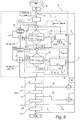
- Fig. 6 to 8 various embodiments of Verdrängerpumpensystemen described, each having a control module, which is formed as a separate unit, and which is spaced from the drive module and housed in a separate housing.
- the mode of operation of the control module present as a control module will be explained in detail on the basis of the exemplary embodiments. This mode of operation of the control modules shown can also from the in the Fig. 1 to 5 be implemented control modules.
- a positive displacement pump system 1 schematically the construction of a positive displacement pump system 1 is shown.
- This comprises a in the embodiment shown as a single or multi-spindle pump, in particular three-spindle pump, trained positive displacement pump 2.
- the positive displacement pump 2 is operatively connected to a motor shaft of a trained as an electric motor displacement pump motor 3, which comprises a frequency converter 4, depending on a generated by a controller 6
- Manipulated variable Y S or a corrected manipulated variable Y ' S or possibly multiple times corrected manipulated variable Y' S controls the energization of the motor windings of the positive displacement pump motor 3 and / or regulates.
- Displacement pump motor and frequency converter form a drive module 207.
- a corrected manipulated variable Y ' S comprises the positive displacement pump 1, for example, formed by a microcontroller control means 5, comprising a previously mentioned controller 6 and logic means 7.
- the control means 5 are as separate from the drive module 207 control module 202 with its own Housing before.
- the control means 5 are preferably preceded by this separate suitss istnvorgabesch 8, for example, a process control, which provide the control means 5 with a reference variable W, for example, a nominal volume flow or a desired pressure representing electrical voltage signal.
- a reference variable W for example, a nominal volume flow or a desired pressure representing electrical voltage signal.
- the reference variable W and an externally supplied first actual operating parameter X are supplied to the controller 6, more precisely to a difference former 9 of the controller 6, which calculates the difference XW.
- the actual controller 6, which is designed, for example, as a PI or PID controller, thus determines a manipulated variable Y S on the basis of the reference variable W and the first actual operating parameter X measured here . This is not fed directly to the frequency converter 4 as in the prior art. but first passes through logic means 7.
- first comparison means 10 which compare the manipulated variable Y S generated by the controller 6 with at least a first limit, preferably a maximum to be observed first limit Y Grenzmax and / or a minimum to be observed limit Y Grenzmin .
- a comparison value standing in a functional relationship with the manipulated variable Y S can be calculated in the calculation thereof according to a (not) shown (optional) comparison value specification means on the basis of the manipulated variable Y s functional relationship and at least one actual operating parameters, for example, the first actual operating parameters X and at least one further, to be explained later further actual operating parameters can be incorporated.
- the comparison value specification means may, according to a functional relationship for calculating the comparison value, take into account at least one geometry parameter of the positive displacement pump and / or a delivery fluid parameter, which must then also be taken into account when taking into account the limit value.
- this additional comparison value calculation step is saved and the manipulated variable Y S is compared directly with at least one first limit value Y limit max and / or Y limit value, wherein the at least one first limit value represents a positive displacement pump protection limit whose exceeding or falling below a defect the positive displacement pump has or could have.
- the comparison means 10 is associated with a first functional unit 11, which includes first correction means 13 in addition to first limit value specification means 12.
- the functional unit 11 calculates the at least one first limit value Y Kirmax , Y Kirmin of the comparison means 10 is supplied in addition to the manipulated variable Y S generated by the controller 6.
- the comparison means now check whether the manipulated variable Y S falls below a maximum first limit value Y réellemax and / or whether the manipulated variable Y S has a minimum first value Limit Y exceeds limit.
- the manipulated variable Y S is a permissible control variable which does not endanger the positive-displacement pump, which can be supplied to further comparisons and correction routines, not shown, or as shown directly as input signal to the frequency converter 4 of the positive-displacement pump motor 3 on this basis controls.
- the first actual operating unit 11 is supplied with the first actual operating parameter X and another measured or calculated actual operating parameter Y H and / or X H , wherein the actual operating parameter Y H in the exemplary embodiment shown is an auxiliary manipulated variable of the frequency converter, for example, a rotational frequency setpoint or a torque setpoint of the frequency converter. These are not measured values, but based on at least one actual parameter, for example based on a current control measurement calculated by the frequency converter, in particular simulated values.
- the further actual operating parameter X H is an auxiliary control variable, for example an engine and / or positive displacement pump speed or a torque, which are preferably measured directly on the engine 3.
- an operating parameter for example the first actual operating parameter, here the actual value of the controlled variable from the process control path 14 is considered and at least one further actual operating parameter Y H , X H or a, preferably measured Hauptstellêt Y HH for the process control variable X, for example, a pressure or a flow.
- the first correction means 13 In the event that an exceeding of the maximum first limit value Y Grenzmax and / or a falling below the minimum first limit value Y Mariemin is detected by the comparison means, this is reported to the first function unit 11, the first correction means 13 then a corrected manipulated variable Y 'S determine taking into account the first actual operating parameter X and one of the aforementioned further actual operating parameters Y H , X H , Y HH .
- This corrected manipulated variable Y ' S can then, as shown, be fed to the comparison means as an input variable for comparison with a first limit value Y Grenzmax and / or Y Grenzmin or bypassing the Comparison means (not shown) a further comparison and correction procedure or directly the frequency converter 4 as an input signal.
- specific geometry parameters GP and / or conveying fluid parameters FP specific to the conveying fluid can be supplied to the first limiting value specification means 12 and / or the first correction means 13 for the positive displacement pump assigned to the control means 5, which, in the context of a functional relationship, find their way into the calculation of the first limit values Y limit max , Y limit min , and / or the corrected manipulated variable Y ' S.
- the corrected manipulated variable Y ' S is the maximum or minimum permissible first limit value Y réellemax , Y Kirmin , as close as possible to the manipulated variable Y S generated by the controller.
- the first limit value specification means 12 and the first correction means 13 include a common computer (computer means), since the corrected manipulated variable Y ' S in the embodiment shown corresponds to a first limit value Y limit max , Y limit min .
- the manipulated variable Y S generated by the controller is overwritten with the corrected manipulated variable Y ' S.
- the first correction means 13 and the first limit value specification means 12 can be realized completely separately, ie with separate calculation means, ie in separate functional units.
- the corrected manipulated variable Y ' S should correspond to a first limit value, in which case, as in Fig. 1 shown limit value setting means 12 and correction means 13 merge together, so have a common calculation routine.
- the first actual operating parameter X corresponds to the actual controlled variable, in the exemplary embodiment shown a pressure, measured in bar. It is assumed that the reference variable X is a pressure and is initially 20 bar. Likewise, the actual operating parameter X is measured as 20 bar.
- the controller 6 determines a new manipulated variable Y S , in this case a speed-proportional voltage value, which is significantly smaller than in a previous run or in a previous calculation.
- the first threshold value setting means 12 calculates a minimum allowable limit value Y limit min. This represents in the embodiment shown a minimum allowable speed. Maintaining a minimum permissible speed is desirable in order to avoid the risk of lubricant leakage when this minimum permissible speed is exceeded.
- Y Grenzmax corresponds to the minimum permissible limit value. This is a minimum permissible speed (n permissible ).
- the first actual operating parameter X is in this case the measured controlled variable, here the new actual pressure of 10 bar.
- the factor • ⁇ is a further operating parameters, namely a measure for the, in particular via a temperature measurement of the conveying fluid certain operating viscosity of the fluid or for the situation influence of viscosity on the maximum allowable pressure. This value is 10 0.32 for the particular medium in the embodiment shown.
- the constant k is the correction value for the lubricity of the medium, this is exemplified by 0.75 for the particular medium.
- the constant b is a correction value for the tribocharging capability of the pump casing. This is in the illustrated embodiment 1.
- the pump-specific characteristic c is a characteristic value for the radially loaded rotor diameter. This is for example in the embodiment shown 0.55.
- the minimum permissible limit value Y Grenzmin is supplied to the first comparison means 10 which compare the manipulated variable Y S determined by the controller 6 with this. Depending on the comparison, either the manipulated variable Y S determined by the controller is transmitted to the frequency converter or a corrected manipulated variable Y ' S is determined by the first correction means, which preferably corresponds to the previously calculated (or newly calculated) minimum permissible limit value Y limit min .
- the first actual operating parameter X corresponds to the actual controlled variable, here a pressure.
- An actual pressure of 20 bar is measured.
- the setpoint of the controlled variable i. the reference variable W from 20 to 30 bar.
- the disturbance variable there is a change in the disturbance variable. It is believed that the flow resistance increases due to a smaller flow area, i. a smaller fürström trimmessers, for example, as a result of a tool change.
- the aforementioned manipulated variable Ys is the minimum limit for refracting Y Kirmin (first threshold value) which represents the minimum allowable speed. The calculation is based on the functional relationship specified in the first embodiment.
- the first correction means 13 Since the manipulated variable Y S falls below the minimum permissible limit value Y limit value, ie the minimum permissible speed, the first correction means 13 output a corrected manipulated variable Y ' S , which is transmitted to the frequency converter instead of the manipulated variable Y S.
- the corrected manipulated variable Y ' S preferably corresponds to the calculated minimum permissible limit value Y limit min .
- the reference variable W is a volume flow measured in l / min.
- the first actual operating parameter X is a measured volume flow. It is assumed that the volumetric flow demand increases during operation. In the example shown, the reference value is to double, namely from 1500 l / min to 3000 l / min.
- the controller 6 determines a manipulated variable Y S , here a speed.
- This manipulated variable Y S ie the speed specified by the controller 6 is compared by the comparison means 10 with a maximum permissible speed, ie a first limit value Y Grenzmax . This maximum permissible speed is determined based on the NPSH available , ie based on the existing NPSH or the holding pressure level of the system.
- Fig. 4 In the diagram according to Fig. 4 is indicated on the left vertical axis of the NPSH in meters of water (mWs). On the right vertical axis, the speed is given in revolutions per minute. On the horizontal axis, the axial velocity of the fluid is given in m / s.
- the diagram refers to an exemplary pump with a size 20 and a lead angle of the spindle of 56 °.
- the linearly rising line characterizes the axial velocity v ax of the medium (delivery fluid) as a function of the rotational speed.
- the first limit value Y Stahlmax ie the maximum permissible rotational speed
- the diagram must move up to the linear line.
- the maximum permissible speed ie the first limit value Y Kirmax
- the reference variable ie the required volume flow doubles, which is 3000 l / min due to the linear relationship between a manipulated variable change from the assumed 1500 rpm. Since this manipulated variable Y S of 3000 1 / min is smaller than the first limit Y Grenzmax of about 3800 1 / min, the manipulated variable Y S can be transmitted to the frequency converter 4 as an input.
- the correction means 13 will correct the manipulated variable Y S given by the controller 6 by a corrected manipulated variable Y ' S , which corresponds to, for example, the first limit, ie 3800 1 / min in the present example.
- the embodiment according to Fig. 7 differs from the embodiment according to Fig. 6 merely in that the manipulated variable Y S generated by the controller 6 is not compared with at least one first limit value assuring or representing the positive displacement pump protection, but with at least one second limit value ensuring the delivery fluid quality. In the exemplary embodiment shown, this is a second limit value. Also at Fig. 7 The control means are present as separate from the drive module control module.
- the at least one second limit value Y Grenzmax , Y Grenzmin ensures compliance with the delivery fluid quality .
- a single, maximum second limit value Y limit-max is provided by second limit value specification means 15, wherein, alternatively, a plurality of second limit values, eg an additional one minimum limit Y limit min , which can be calculated to ensure the conveyed fluid quality .
- each second comparison means 16 determines whether the manipulated variable generated by the controller 6 Y S or a corrected already in a preceding, not included here further correction procedure manipulated variable exceeds the second threshold value Y réellemin by a certain amount. If the manipulated variable Y S is less than or equal to the maximum limit value, the manipulated variable Y S generated by the controller 6 or supplied to the comparison means 16 is made available (calculated) to the frequency converter 4.
- the second limit value specification means 15 take into account the first actual operating parameter X and at least one further (other) actual operating parameter, for example an auxiliary manipulated variable Y H , an auxiliary controlled variable X H and / or a skin manipulated variable YHH . It can also be realized that, in addition, geometry parameters GP of the displacement pump and / or delivery fluid parameters FP, as well as the vibration, are taken into account in the calculation.
- the fourth example concerns the protection of the medium, i.
- the second limit value is determined such that the manipulated variable does not result in a negative impairment of a quality parameter of the delivery fluid (delivery medium) conveyed by the positive displacement pump.
- the second limit value corresponds to a maximum permissible speed.
- the first operating parameter X is a volume flow of the process line.
- the determination of the second limit value includes functional conditions of the pump, ie speed ratios are taken into account, namely the angular velocity difference of the rotating positive displacement rotors (spindles) relative to the stationary pump housing.
- the velocity ratios in the columns are directly proportional to the pump speed and there is an inversely directly proportional relationship to the size of the function gap, ie the actual linear shear rate.
- This functional gap is dependent on pump-specific conditions, namely on the actual radial gap, ie on the firmly set pump rotor radial clearance and also on current operating conditions, namely the current pressure load of the delivery fluid, as well as the current viscosity of the delivery fluid.
- the latter two further actual operating parameters are measured and are taken into account in the calculation of the second limit value Y Grenzmax , ie in the calculation of the maximum permissible rotational speed.
- a delivery fluid having a dynamic viscosity ⁇ of 5 Pas is delivered.
- the maximum permissible speed therefore corresponds to the limit value Y réellemax.
- the embodiment according to Fig. 8 combines the embodiments according to the Fig. 6 and Fig. 7 ie, the control means 5 are designed in such a way that the manipulated variable Y S output by the controller 6 can be compared both with at least one first limit value (pump protection limit value) and with at least one second limit value (medium protection limit value).
- the control variable Y S generated by the controller 6 is first compared with a first and then with a second threshold, wherein the reverse arrangement is of course feasible, ie, that is compared first with a second and then with a first limit.
- the output value of the first comparison forms the input variable for the second comparison, wherein the output variable of the first comparison can be the uncorrected manipulated variable Y S , namely if there is no limit value overshoot or undershoot in the first comparison and Y s is thus not corrected or, alternatively, by a manipulated variable Y ' S corrected by the first comparison means 10.
- Y S or Y ' S are then the input variables for the second comparison means 16. If no correction is made here, the input value for the second comparison Y S or Y' S is sent to the frequency converter 4 or in the case of a correction the corrected manipulated variable Y " S.
- first and second decision-making means 20, 21 are provided in which it is determined whether a pump protection comparison or a medium protection comparison is to be carried out.
- the respective decision can for example be specified by software, so that the user alternatively only one Pump protection comparison or a medium protection comparison can realize, or both comparison operations.
- the manipulated variable is a speed signal for the pump, the pump speed being plotted in the diagram on the left vertical axis.
- the delivery pressure measured at the discharge nozzle of the pump, flows into the calculation of the first limit value, the delivery fluid pressure being plotted on the right vertical axis.
- the delivery fluid viscosity (medium viscosity) flows into the calculation of the first limit value as a further actual operating parameter, the medium viscosity being plotted on the horizontal lower axis.
- the delivery fluid volume flow or the pump speed or the delivery fluid pressure into consideration. In the specific embodiment, it is assumed that the delivery fluid pressure is the reference variable.
- the conveying fluid viscosity due to a corresponding medium change from 12mm 2 / s to 9 mm 2 / s, to 6 mm 2 / s, to 4 mm 2 / s and then (stepwise) up to 2mm 2 / s drops.
- the delivery fluid volume flow may fluctuate.
- the reference variable ie the process pressure (delivery fluid pressure) should initially be kept at 10bar, then 20bar, etc., ie incrementally by 10bar each up to a maximum of 50bar. In other words, the reference variable will gradually change from 10bar to 50bar.
- the controller outputs a manipulated variable (Y S ) as a function of the reference variable (W).
- the first limit value specification means calculate a first limit value, in the present case a minimum rotational speed Y limit min as a function of the first actual operating parameter, here the delivery fluid pressure and the further actual operating parameter, here the medium viscosity, wherein in the concrete exemplary embodiment the medium viscosity is determined indirectly via the delivery fluid temperature.
- the first limit value in the present case a minimum rotational speed Y limit min as a function of the first actual operating parameter, here the delivery fluid pressure and the further actual operating parameter, here the medium viscosity, wherein in the concrete exemplary embodiment the medium viscosity is determined indirectly via the delivery fluid temperature.
- the minimum speed would cause a defect state of the positive displacement pump.
- the comparison means compare in the specific embodiment of the controller predetermined manipulated variable, ie, a speed signal with the first limit value calculated by the first threshold value setting means. If the manipulated variable in the illustrated embodiment is above this first limit value, the manipulated variable is forwarded to the frequency converter as an input signal.
- a corrected manipulated variable is determined or determined as an input signal in the embodiment shown and passed on to the frequency converter as a corrected manipulated variable in the embodiment shown by the first correction means passing on the first limit value determined by the limit value specification means.
Landscapes
- Engineering & Computer Science (AREA)
- Mechanical Engineering (AREA)
- General Engineering & Computer Science (AREA)
- Computer Hardware Design (AREA)
- Control Of Positive-Displacement Pumps (AREA)
- Compressors, Vaccum Pumps And Other Relevant Systems (AREA)
- Compressor (AREA)
- Details And Applications Of Rotary Liquid Pumps (AREA)
Applications Claiming Priority (2)
| Application Number | Priority Date | Filing Date | Title |
|---|---|---|---|
| DE102011050018A DE102011050018A1 (de) | 2011-04-29 | 2011-04-29 | Pumpen-System |
| PCT/EP2012/057664 WO2012146662A2 (de) | 2011-04-29 | 2012-04-26 | Pumpen-system |
Publications (2)
| Publication Number | Publication Date |
|---|---|
| EP2702272A2 EP2702272A2 (de) | 2014-03-05 |
| EP2702272B1 true EP2702272B1 (de) | 2018-11-14 |
Family
ID=46197228
Family Applications (1)
| Application Number | Title | Priority Date | Filing Date |
|---|---|---|---|
| EP12724580.1A Not-in-force EP2702272B1 (de) | 2011-04-29 | 2012-04-26 | Pumpen-system |
Country Status (6)
Families Citing this family (25)
| Publication number | Priority date | Publication date | Assignee | Title |
|---|---|---|---|---|
| CN104106206A (zh) * | 2012-03-12 | 2014-10-15 | 富士电机株式会社 | 电动机驱动系统 |
| US10495084B2 (en) * | 2012-04-11 | 2019-12-03 | Itt Manufacturing Enterprises Llc | Method for twin screw positive displacement pump protection |
| US10046351B2 (en) * | 2014-07-14 | 2018-08-14 | Graco Minnesota Inc. | Material dispense tracking and control |
| JP6476696B2 (ja) * | 2014-09-30 | 2019-03-06 | アイシン精機株式会社 | 燃料電池システム |
| CN104900278B (zh) * | 2015-06-19 | 2017-02-22 | 中国核动力研究设计院 | 一种控制能动与非能动系统转换过程中泵流量的模拟方法 |
| US11624362B2 (en) * | 2015-08-07 | 2023-04-11 | Magpumps Limited | Device for pumping fluid |
| US10473097B2 (en) | 2015-09-02 | 2019-11-12 | Tigerflow Systems, Llc | System and method for speed control of variable speed pumping systems |
| WO2020033682A1 (en) | 2018-08-08 | 2020-02-13 | Fluid Handling Llc | Variable speed pumping control system with active temperature and vibration monitoring and control means |
| EP3629113A1 (de) * | 2018-09-28 | 2020-04-01 | Siemens Aktiengesellschaft | Projektieren, konfigurieren und instandhalten einer antriebsvorrichtung |
| DE102019108781A1 (de) * | 2019-04-03 | 2020-10-08 | Peri Gmbh | Computergestütztes Verfahren und Einrichtung zur optimierten Steuerung der Förderleistung einer Betonpumpe oder dergleichen |
| DE102019112792A1 (de) | 2019-05-15 | 2020-11-19 | Leistritz Pumpen Gmbh | Verfahren zur Ermittlung eines Durchflussvolumens eines durch eine Pumpe geförderten Fluids |
| CN110332102B (zh) * | 2019-07-23 | 2021-08-20 | 珠海格力电器股份有限公司 | 自动排空水泵的控制方法、装置相应设备及存储介质 |
| DE102019219039A1 (de) * | 2019-12-06 | 2021-06-10 | Robert Bosch Gmbh | Getriebepumpenanordnung, Verfahren zum Betreiben einer Getriebepumpe und Computerprogrammprodukt |
| CN112697975A (zh) * | 2020-12-15 | 2021-04-23 | 潍柴动力股份有限公司 | 尿素浓度的测量方法及装置、电子设备、存储介质 |
| GB2602038A (en) * | 2020-12-16 | 2022-06-22 | Edwards Ltd | Bearing wear monitoring |
| DE102020133760A1 (de) * | 2020-12-16 | 2022-06-23 | Leistritz Pumpen Gmbh | Verfahren zur Förderung eines Fluids durch eine Schraubenspindelpumpe und Schraubenspindelpumpe |
| RU207356U1 (ru) * | 2021-03-23 | 2021-10-25 | Общество с ограниченной ответственностью "Кварт" | Мобильный насосный модуль слива-налива жидкостей, кислот и щелочей |
| CN112983798B (zh) * | 2021-03-25 | 2023-02-24 | 烟台杰瑞石油装备技术有限公司 | 应用于电驱压裂设备的控制方法及其控制装置 |
| EP4120558A1 (en) * | 2021-07-15 | 2023-01-18 | Abb Schweiz Ag | A method, an arrangement and a frequency converter for controlling vibration of an electric machine |
| JP2023127381A (ja) * | 2022-03-01 | 2023-09-13 | 株式会社島津製作所 | 真空ポンプの制御装置、及び、制御方法 |
| CN115085630B (zh) * | 2022-07-21 | 2024-05-28 | 国网新源控股有限公司 | 一种静止变频器启动过程中电机振动优化抑制方法 |
| CN115454153A (zh) * | 2022-10-26 | 2022-12-09 | 北京七星华创流量计有限公司 | 质量流量控制器及其流量控制方法 |
| CN116146357B (zh) * | 2023-02-27 | 2023-09-26 | 贵州航天林泉电机有限公司 | 一种电动燃油泵前馈控制方法 |
| CN116624360B (zh) * | 2023-05-25 | 2024-02-09 | 广东托亚电器科技有限公司 | 一种低压快速充气泵送结构及其在车载充气泵中的应用 |
| DE102023124932A1 (de) * | 2023-09-15 | 2025-03-20 | Ebm-Papst Mulfingen Gmbh & Co. Kg | Verfahren und Vorrichtung zur Steuerung einer Strömungserzeugungseinrichtung |
Family Cites Families (27)
| Publication number | Priority date | Publication date | Assignee | Title |
|---|---|---|---|---|
| DE2823558C2 (de) * | 1978-05-30 | 1983-08-11 | Vanbelle, Jean William, 8174 Benediktbeuern | Vorrichtung zum Überwachen komplexer Arbeitsmaschinen, wie Kompressoranlagen |
| DE29724347U1 (de) * | 1996-07-29 | 2000-11-16 | Gebr. Becker Gmbh & Co, 42279 Wuppertal | Frequenzumrichter |
| DE19724643A1 (de) * | 1997-06-11 | 1998-12-17 | Sihi Gmbh & Co Kg | Schraubenverdichter und Verfahren zum Betrieb desselben |
| US6097171A (en) | 1998-01-30 | 2000-08-01 | A. O. Smith Corporation | Method and apparatus for controlling an induction motor |
| DE19842565B4 (de) * | 1998-09-03 | 2005-08-25 | Ksb Ag | Automatische Ermittlung der PID-Reglerparameter für einen Druckregelkreis in Mehrpumpenanlagen |
| JP3584279B2 (ja) | 1998-10-30 | 2004-11-04 | 理学電機工業株式会社 | 蛍光x線分析装置 |
| JP2000283056A (ja) * | 1999-03-26 | 2000-10-10 | Hitachi Ltd | 真空ポンプ異常監視システム |
| JP2001012379A (ja) | 1999-06-29 | 2001-01-16 | Aisin Seiki Co Ltd | メンテナンス判定機能付き真空ポンプ |
| US6360717B1 (en) * | 2000-08-14 | 2002-03-26 | Caterpillar Inc. | Fuel injection system and a method for operating |
| US8914300B2 (en) * | 2001-08-10 | 2014-12-16 | Rockwell Automation Technologies, Inc. | System and method for dynamic multi-objective optimization of machine selection, integration and utilization |
| JP2003077907A (ja) | 2001-08-31 | 2003-03-14 | Toshiba Corp | 生産装置の異常停止回避方法及び異常停止回避システム |
| GB0216647D0 (en) * | 2002-07-17 | 2002-08-28 | Schlumberger Holdings | System and method for obtaining and analyzing well data |
| US6890156B2 (en) * | 2002-11-01 | 2005-05-10 | Polyphase Engineered Controls | Reciprocating pump control system |
| DE202005001746U1 (de) | 2004-08-20 | 2005-12-22 | Nash-Elmo Industries Gmbh | Vorrichtung zum Steuern einer Strömungsarbeitsmaschine |
| DE102005014050A1 (de) * | 2005-03-23 | 2006-09-28 | Endress + Hauser Process Solutions Ag | Verfahren zum sicheren Bedienen eines Feldgerätes der Automatisierungstechnik |
| ITRM20050373A1 (it) * | 2005-07-13 | 2007-01-14 | Seko Bono Exacta S P A | Dispositivo di pilotaggio di un elettromagnete di azionamento di una pompa, e relativa pompa elettromagnetica dosatrice. |
| EP1847714B1 (en) * | 2006-04-20 | 2016-11-09 | ABB Oy | Frequency converter for motor pump |
| KR100885919B1 (ko) * | 2007-05-21 | 2009-02-26 | 삼성전자주식회사 | 펌프 폴트 예측 장치 및 펌프 폴트 예측 방법 |
| JP5139523B2 (ja) * | 2007-06-27 | 2013-02-06 | エイチ アール ディー コーポレーション | ニトロベンゼンを製造するためのシステム及び方法 |
| GB2451876A (en) * | 2007-08-15 | 2009-02-18 | Mono Pumps Ltd | Pump system for a pressure sewer system |
| DE102008063927B4 (de) | 2007-12-21 | 2025-07-24 | Robert Bosch Gmbh | Verfahren zur Bestimmung von Lastkollektiven von hydrostatischen Maschinen sowie entsprechendes Steuergerät |
| BRPI0800251B1 (pt) * | 2008-02-22 | 2021-02-23 | Embraco Indústria De Compressores E Soluções Em Refrigeração Ltda | sistema e método de controle de compressor linear |
| US20090220352A1 (en) | 2008-02-29 | 2009-09-03 | Carstensen Peter T | Method and Device for Monitoring and Controlling a Hydraulic Actuated Process |
| US9678496B2 (en) * | 2008-05-23 | 2017-06-13 | Amtec Meter & Controls, Inc. | Concrete material dispensing system |
| CN201363264Y (zh) * | 2009-03-18 | 2009-12-16 | 纪国忠 | 循环水泵恒温自动控制系统 |
| US9164501B2 (en) * | 2009-10-05 | 2015-10-20 | Fisher-Rosemount Systems, Inc. | Methods and apparatus to manage data uploading in a process control environment |
| US8483916B2 (en) * | 2011-02-28 | 2013-07-09 | Caterpillar Inc. | Hydraulic control system implementing pump torque limiting |
-
2011
- 2011-04-29 DE DE102011050018A patent/DE102011050018A1/de not_active Ceased
-
2012
- 2012-04-26 WO PCT/EP2012/057664 patent/WO2012146662A2/de active Application Filing
- 2012-04-26 EP EP12724580.1A patent/EP2702272B1/de not_active Not-in-force
- 2012-04-26 JP JP2014506867A patent/JP2014512488A/ja active Pending
- 2012-04-26 CN CN201280020693.XA patent/CN103620218B/zh not_active Expired - Fee Related
- 2012-04-26 US US14/113,666 patent/US9995297B2/en not_active Expired - Fee Related
-
2017
- 2017-11-24 JP JP2017226074A patent/JP2018066375A/ja active Pending
-
2018
- 2018-05-11 US US15/977,087 patent/US20180258926A1/en not_active Abandoned
Non-Patent Citations (1)
| Title |
|---|
| None * |
Also Published As
| Publication number | Publication date |
|---|---|
| EP2702272A2 (de) | 2014-03-05 |
| CN103620218B (zh) | 2016-12-07 |
| JP2018066375A (ja) | 2018-04-26 |
| WO2012146662A2 (de) | 2012-11-01 |
| CN103620218A (zh) | 2014-03-05 |
| US20180258926A1 (en) | 2018-09-13 |
| JP2014512488A (ja) | 2014-05-22 |
| DE102011050018A1 (de) | 2012-10-31 |
| US9995297B2 (en) | 2018-06-12 |
| US20140056720A1 (en) | 2014-02-27 |
| WO2012146662A3 (de) | 2013-05-23 |
Similar Documents
| Publication | Publication Date | Title |
|---|---|---|
| EP2702272B1 (de) | Pumpen-system | |
| EP2702459A1 (de) | Steuermittel zum ansteuern eines frequenzumrichters sowie ansteuerverfahren | |
| EP1564411B1 (de) | Verfahren zur Ermittlung von Fehlern beim Betrieb eines Pumpenaggregates | |
| EP2145112B2 (de) | Einrichtung und verfahren zur störungsüberwachung | |
| EP0228665B1 (de) | Verfahren zur Pumpgrenzregelung von Turbokompressoren | |
| EP1892597A1 (de) | Zustandsüberwachung von Maschinen und technischen Anlagen | |
| DE112013004970T5 (de) | Drucksteuerung mit Hilfe eines Phasenstromes und anfänglicher Einstellung bei einer Fahrzeugbaureihe | |
| DE102015207682B4 (de) | Verfahren zur Regelung einer Kraftstoffförderpumpe | |
| DE102011013151A1 (de) | Verfahren zur Kühlmittelversorgung, Schaltanordnung und Werkzeugmaschine | |
| EP3830422A1 (de) | Vakuumpumpe | |
| DE102006032648B4 (de) | Diagnosesystem und Verfahren zur Zustandsüberwachung und Erkennung von Funktionsminderungen und Ausfällen an verdichtende und rotierende Maschinen | |
| DE102010009164A1 (de) | Verfahren und Vorrichtung zum Steuern einer Textilmaschine oder eines angetriebenen Teils einer Textilmaschine | |
| EP2628391B1 (de) | Verfahren zum Füllen von Würsten mit pastöser Masse sowie Füllmaschine zum Durchführen dieses Verfahrens | |
| WO2021018840A1 (de) | Verfahren zum überwachen eines brennstoffzufuhrsystems einer brennkraftmaschine und brennkraftmaschine zur durchführung eines solchen verfahrens | |
| DE102007003695B4 (de) | Verfahren und Vorrichtung zum Steuern von Antrieben | |
| WO2020127007A1 (de) | Steuerungsvorrichtung und verfahren zur regelung eines volumenstroms eines fluids in einem antriebsstrang eines kraftfahrzeugs | |
| DE102015202777A1 (de) | Verfahren zur Regelung einer Kraftstoffförderpumpe | |
| DE102007014325B4 (de) | Verfahren und Vorrichtung zur Überwachung eines Drucksignals, insbesondere eines Raildrucksignals eines Common-Rails-Systems | |
| DE102011120686A1 (de) | Verfahren zum Überwachen einer Pumpe | |
| EP2165062B1 (de) | Verfahren und vorrichtung zur drehzahlregler-funktionsüberwachung | |
| EP4261413B1 (de) | Vorrichtung und verfahren zum ermitteln eines zustandes, insbesondere eines verschleisszustandes, einer verdrängereinheit | |
| DE102005003591A1 (de) | Sekundärluftdiagnose einer Brennkraftmaschine | |
| DE102017108281B4 (de) | Brennkraftmaschine und Verfahren zum Überwachen der Brennkraftmaschine | |
| EP3596807B1 (de) | Spindelantrieb, aufweisend einen elektromotor und einen von dem elektromotor angetriebenen spindeltrieb, und verfahren zum betreiben eines spindelantriebs | |
| DE102004044185A1 (de) | Verfahren und Vorrichtung zum Ermitteln eines Fehlerzustandes eines rotierenden Verdichters |
Legal Events
| Date | Code | Title | Description |
|---|---|---|---|
| PUAI | Public reference made under article 153(3) epc to a published international application that has entered the european phase |
Free format text: ORIGINAL CODE: 0009012 |
|
| 17P | Request for examination filed |
Effective date: 20131028 |
|
| AK | Designated contracting states |
Kind code of ref document: A2 Designated state(s): AL AT BE BG CH CY CZ DE DK EE ES FI FR GB GR HR HU IE IS IT LI LT LU LV MC MK MT NL NO PL PT RO RS SE SI SK SM TR |
|
| DAX | Request for extension of the european patent (deleted) | ||
| STAA | Information on the status of an ep patent application or granted ep patent |
Free format text: STATUS: EXAMINATION IS IN PROGRESS |
|
| 17Q | First examination report despatched |
Effective date: 20170808 |
|
| GRAP | Despatch of communication of intention to grant a patent |
Free format text: ORIGINAL CODE: EPIDOSNIGR1 |
|
| STAA | Information on the status of an ep patent application or granted ep patent |
Free format text: STATUS: GRANT OF PATENT IS INTENDED |
|
| INTG | Intention to grant announced |
Effective date: 20180725 |
|
| GRAS | Grant fee paid |
Free format text: ORIGINAL CODE: EPIDOSNIGR3 |
|
| GRAA | (expected) grant |
Free format text: ORIGINAL CODE: 0009210 |
|
| STAA | Information on the status of an ep patent application or granted ep patent |
Free format text: STATUS: THE PATENT HAS BEEN GRANTED |
|
| AK | Designated contracting states |
Kind code of ref document: B1 Designated state(s): AL AT BE BG CH CY CZ DE DK EE ES FI FR GB GR HR HU IE IS IT LI LT LU LV MC MK MT NL NO PL PT RO RS SE SI SK SM TR |
|
| REG | Reference to a national code |
Ref country code: CH Ref legal event code: EP Ref country code: AT Ref legal event code: REF Ref document number: 1065141 Country of ref document: AT Kind code of ref document: T Effective date: 20181115 |
|
| REG | Reference to a national code |
Ref country code: DE Ref legal event code: R096 Ref document number: 502012013817 Country of ref document: DE |
|
| REG | Reference to a national code |
Ref country code: IE Ref legal event code: FG4D Free format text: LANGUAGE OF EP DOCUMENT: GERMAN |
|
| REG | Reference to a national code |
Ref country code: NL Ref legal event code: MP Effective date: 20181114 |
|
| REG | Reference to a national code |
Ref country code: LT Ref legal event code: MG4D |
|
| PG25 | Lapsed in a contracting state [announced via postgrant information from national office to epo] |
Ref country code: ES Free format text: LAPSE BECAUSE OF FAILURE TO SUBMIT A TRANSLATION OF THE DESCRIPTION OR TO PAY THE FEE WITHIN THE PRESCRIBED TIME-LIMIT Effective date: 20181114 Ref country code: LV Free format text: LAPSE BECAUSE OF FAILURE TO SUBMIT A TRANSLATION OF THE DESCRIPTION OR TO PAY THE FEE WITHIN THE PRESCRIBED TIME-LIMIT Effective date: 20181114 Ref country code: NO Free format text: LAPSE BECAUSE OF FAILURE TO SUBMIT A TRANSLATION OF THE DESCRIPTION OR TO PAY THE FEE WITHIN THE PRESCRIBED TIME-LIMIT Effective date: 20190214 Ref country code: FI Free format text: LAPSE BECAUSE OF FAILURE TO SUBMIT A TRANSLATION OF THE DESCRIPTION OR TO PAY THE FEE WITHIN THE PRESCRIBED TIME-LIMIT Effective date: 20181114 Ref country code: IS Free format text: LAPSE BECAUSE OF FAILURE TO SUBMIT A TRANSLATION OF THE DESCRIPTION OR TO PAY THE FEE WITHIN THE PRESCRIBED TIME-LIMIT Effective date: 20190314 Ref country code: HR Free format text: LAPSE BECAUSE OF FAILURE TO SUBMIT A TRANSLATION OF THE DESCRIPTION OR TO PAY THE FEE WITHIN THE PRESCRIBED TIME-LIMIT Effective date: 20181114 Ref country code: LT Free format text: LAPSE BECAUSE OF FAILURE TO SUBMIT A TRANSLATION OF THE DESCRIPTION OR TO PAY THE FEE WITHIN THE PRESCRIBED TIME-LIMIT Effective date: 20181114 Ref country code: BG Free format text: LAPSE BECAUSE OF FAILURE TO SUBMIT A TRANSLATION OF THE DESCRIPTION OR TO PAY THE FEE WITHIN THE PRESCRIBED TIME-LIMIT Effective date: 20190214 |
|
| PG25 | Lapsed in a contracting state [announced via postgrant information from national office to epo] |
Ref country code: GR Free format text: LAPSE BECAUSE OF FAILURE TO SUBMIT A TRANSLATION OF THE DESCRIPTION OR TO PAY THE FEE WITHIN THE PRESCRIBED TIME-LIMIT Effective date: 20190215 Ref country code: RS Free format text: LAPSE BECAUSE OF FAILURE TO SUBMIT A TRANSLATION OF THE DESCRIPTION OR TO PAY THE FEE WITHIN THE PRESCRIBED TIME-LIMIT Effective date: 20181114 Ref country code: NL Free format text: LAPSE BECAUSE OF FAILURE TO SUBMIT A TRANSLATION OF THE DESCRIPTION OR TO PAY THE FEE WITHIN THE PRESCRIBED TIME-LIMIT Effective date: 20181114 Ref country code: SE Free format text: LAPSE BECAUSE OF FAILURE TO SUBMIT A TRANSLATION OF THE DESCRIPTION OR TO PAY THE FEE WITHIN THE PRESCRIBED TIME-LIMIT Effective date: 20181114 Ref country code: AL Free format text: LAPSE BECAUSE OF FAILURE TO SUBMIT A TRANSLATION OF THE DESCRIPTION OR TO PAY THE FEE WITHIN THE PRESCRIBED TIME-LIMIT Effective date: 20181114 Ref country code: PT Free format text: LAPSE BECAUSE OF FAILURE TO SUBMIT A TRANSLATION OF THE DESCRIPTION OR TO PAY THE FEE WITHIN THE PRESCRIBED TIME-LIMIT Effective date: 20190314 |
|
| PG25 | Lapsed in a contracting state [announced via postgrant information from national office to epo] |
Ref country code: PL Free format text: LAPSE BECAUSE OF FAILURE TO SUBMIT A TRANSLATION OF THE DESCRIPTION OR TO PAY THE FEE WITHIN THE PRESCRIBED TIME-LIMIT Effective date: 20181114 Ref country code: CZ Free format text: LAPSE BECAUSE OF FAILURE TO SUBMIT A TRANSLATION OF THE DESCRIPTION OR TO PAY THE FEE WITHIN THE PRESCRIBED TIME-LIMIT Effective date: 20181114 Ref country code: DK Free format text: LAPSE BECAUSE OF FAILURE TO SUBMIT A TRANSLATION OF THE DESCRIPTION OR TO PAY THE FEE WITHIN THE PRESCRIBED TIME-LIMIT Effective date: 20181114 Ref country code: IT Free format text: LAPSE BECAUSE OF FAILURE TO SUBMIT A TRANSLATION OF THE DESCRIPTION OR TO PAY THE FEE WITHIN THE PRESCRIBED TIME-LIMIT Effective date: 20181114 |
|
| REG | Reference to a national code |
Ref country code: DE Ref legal event code: R097 Ref document number: 502012013817 Country of ref document: DE |
|
| PG25 | Lapsed in a contracting state [announced via postgrant information from national office to epo] |
Ref country code: SK Free format text: LAPSE BECAUSE OF FAILURE TO SUBMIT A TRANSLATION OF THE DESCRIPTION OR TO PAY THE FEE WITHIN THE PRESCRIBED TIME-LIMIT Effective date: 20181114 Ref country code: RO Free format text: LAPSE BECAUSE OF FAILURE TO SUBMIT A TRANSLATION OF THE DESCRIPTION OR TO PAY THE FEE WITHIN THE PRESCRIBED TIME-LIMIT Effective date: 20181114 Ref country code: EE Free format text: LAPSE BECAUSE OF FAILURE TO SUBMIT A TRANSLATION OF THE DESCRIPTION OR TO PAY THE FEE WITHIN THE PRESCRIBED TIME-LIMIT Effective date: 20181114 Ref country code: SM Free format text: LAPSE BECAUSE OF FAILURE TO SUBMIT A TRANSLATION OF THE DESCRIPTION OR TO PAY THE FEE WITHIN THE PRESCRIBED TIME-LIMIT Effective date: 20181114 |
|
| PLBE | No opposition filed within time limit |
Free format text: ORIGINAL CODE: 0009261 |
|
| STAA | Information on the status of an ep patent application or granted ep patent |
Free format text: STATUS: NO OPPOSITION FILED WITHIN TIME LIMIT |
|
| 26N | No opposition filed |
Effective date: 20190815 |
|
| PG25 | Lapsed in a contracting state [announced via postgrant information from national office to epo] |
Ref country code: SI Free format text: LAPSE BECAUSE OF FAILURE TO SUBMIT A TRANSLATION OF THE DESCRIPTION OR TO PAY THE FEE WITHIN THE PRESCRIBED TIME-LIMIT Effective date: 20181114 |
|
| REG | Reference to a national code |
Ref country code: DE Ref legal event code: R119 Ref document number: 502012013817 Country of ref document: DE |
|
| REG | Reference to a national code |
Ref country code: CH Ref legal event code: PL |
|
| REG | Reference to a national code |
Ref country code: BE Ref legal event code: MM Effective date: 20190430 |
|
| GBPC | Gb: european patent ceased through non-payment of renewal fee |
Effective date: 20190426 |
|
| PG25 | Lapsed in a contracting state [announced via postgrant information from national office to epo] |
Ref country code: MC Free format text: LAPSE BECAUSE OF FAILURE TO SUBMIT A TRANSLATION OF THE DESCRIPTION OR TO PAY THE FEE WITHIN THE PRESCRIBED TIME-LIMIT Effective date: 20181114 Ref country code: LU Free format text: LAPSE BECAUSE OF NON-PAYMENT OF DUE FEES Effective date: 20190426 |
|
| PG25 | Lapsed in a contracting state [announced via postgrant information from national office to epo] |
Ref country code: DE Free format text: LAPSE BECAUSE OF NON-PAYMENT OF DUE FEES Effective date: 20191101 Ref country code: LI Free format text: LAPSE BECAUSE OF NON-PAYMENT OF DUE FEES Effective date: 20190430 Ref country code: GB Free format text: LAPSE BECAUSE OF NON-PAYMENT OF DUE FEES Effective date: 20190426 Ref country code: CH Free format text: LAPSE BECAUSE OF NON-PAYMENT OF DUE FEES Effective date: 20190430 |
|
| PG25 | Lapsed in a contracting state [announced via postgrant information from national office to epo] |
Ref country code: BE Free format text: LAPSE BECAUSE OF NON-PAYMENT OF DUE FEES Effective date: 20190430 |
|
| PG25 | Lapsed in a contracting state [announced via postgrant information from national office to epo] |
Ref country code: TR Free format text: LAPSE BECAUSE OF FAILURE TO SUBMIT A TRANSLATION OF THE DESCRIPTION OR TO PAY THE FEE WITHIN THE PRESCRIBED TIME-LIMIT Effective date: 20181114 |
|
| PG25 | Lapsed in a contracting state [announced via postgrant information from national office to epo] |
Ref country code: IE Free format text: LAPSE BECAUSE OF NON-PAYMENT OF DUE FEES Effective date: 20190426 |
|
| PG25 | Lapsed in a contracting state [announced via postgrant information from national office to epo] |
Ref country code: FR Free format text: LAPSE BECAUSE OF NON-PAYMENT OF DUE FEES Effective date: 20190430 |
|
| REG | Reference to a national code |
Ref country code: AT Ref legal event code: MM01 Ref document number: 1065141 Country of ref document: AT Kind code of ref document: T Effective date: 20190426 |
|
| PG25 | Lapsed in a contracting state [announced via postgrant information from national office to epo] |
Ref country code: AT Free format text: LAPSE BECAUSE OF NON-PAYMENT OF DUE FEES Effective date: 20190426 |
|
| PG25 | Lapsed in a contracting state [announced via postgrant information from national office to epo] |
Ref country code: CY Free format text: LAPSE BECAUSE OF FAILURE TO SUBMIT A TRANSLATION OF THE DESCRIPTION OR TO PAY THE FEE WITHIN THE PRESCRIBED TIME-LIMIT Effective date: 20181114 |
|
| PG25 | Lapsed in a contracting state [announced via postgrant information from national office to epo] |
Ref country code: HU Free format text: LAPSE BECAUSE OF FAILURE TO SUBMIT A TRANSLATION OF THE DESCRIPTION OR TO PAY THE FEE WITHIN THE PRESCRIBED TIME-LIMIT; INVALID AB INITIO Effective date: 20120426 Ref country code: MT Free format text: LAPSE BECAUSE OF FAILURE TO SUBMIT A TRANSLATION OF THE DESCRIPTION OR TO PAY THE FEE WITHIN THE PRESCRIBED TIME-LIMIT Effective date: 20181114 |
|
| PG25 | Lapsed in a contracting state [announced via postgrant information from national office to epo] |
Ref country code: MK Free format text: LAPSE BECAUSE OF FAILURE TO SUBMIT A TRANSLATION OF THE DESCRIPTION OR TO PAY THE FEE WITHIN THE PRESCRIBED TIME-LIMIT Effective date: 20181114 |