EP2701607B1 - Bone surface image reconstruction using ultrasound - Google Patents
Bone surface image reconstruction using ultrasound Download PDFInfo
- Publication number
- EP2701607B1 EP2701607B1 EP12777556.7A EP12777556A EP2701607B1 EP 2701607 B1 EP2701607 B1 EP 2701607B1 EP 12777556 A EP12777556 A EP 12777556A EP 2701607 B1 EP2701607 B1 EP 2701607B1
- Authority
- EP
- European Patent Office
- Prior art keywords
- bone
- ultrasound
- information
- target
- ultrasonic energy
- Prior art date
- Legal status (The legal status is an assumption and is not a legal conclusion. Google has not performed a legal analysis and makes no representation as to the accuracy of the status listed.)
- Active
Links
- 210000000988 bone and bone Anatomy 0.000 title claims description 165
- 238000002604 ultrasonography Methods 0.000 title description 143
- 238000000034 method Methods 0.000 claims description 173
- 230000033001 locomotion Effects 0.000 claims description 66
- 210000001519 tissue Anatomy 0.000 claims description 26
- 238000002592 echocardiography Methods 0.000 claims description 14
- 238000012634 optical imaging Methods 0.000 claims 2
- 238000003384 imaging method Methods 0.000 description 67
- 238000012285 ultrasound imaging Methods 0.000 description 32
- 239000011159 matrix material Substances 0.000 description 27
- 238000013459 approach Methods 0.000 description 26
- 230000000875 corresponding effect Effects 0.000 description 24
- 239000013598 vector Substances 0.000 description 22
- 238000003780 insertion Methods 0.000 description 19
- 230000037431 insertion Effects 0.000 description 19
- 230000003287 optical effect Effects 0.000 description 14
- 208000014674 injury Diseases 0.000 description 11
- 238000009877 rendering Methods 0.000 description 11
- 108010001267 Protein Subunits Proteins 0.000 description 9
- 238000001727 in vivo Methods 0.000 description 9
- 230000011218 segmentation Effects 0.000 description 9
- 238000004088 simulation Methods 0.000 description 9
- 238000001914 filtration Methods 0.000 description 8
- 230000008569 process Effects 0.000 description 8
- 208000010392 Bone Fractures Diseases 0.000 description 7
- 238000007476 Maximum Likelihood Methods 0.000 description 7
- 238000009826 distribution Methods 0.000 description 7
- 210000002310 elbow joint Anatomy 0.000 description 7
- 238000013519 translation Methods 0.000 description 7
- 230000014616 translation Effects 0.000 description 7
- 238000002059 diagnostic imaging Methods 0.000 description 6
- 238000006073 displacement reaction Methods 0.000 description 6
- 230000000694 effects Effects 0.000 description 6
- 230000006870 function Effects 0.000 description 6
- 230000005865 ionizing radiation Effects 0.000 description 6
- 238000012545 processing Methods 0.000 description 6
- 230000008733 trauma Effects 0.000 description 6
- 206010002091 Anaesthesia Diseases 0.000 description 5
- 208000027418 Wounds and injury Diseases 0.000 description 5
- 230000037005 anaesthesia Effects 0.000 description 5
- 210000003484 anatomy Anatomy 0.000 description 5
- 238000003491 array Methods 0.000 description 5
- 230000008901 benefit Effects 0.000 description 5
- 230000006378 damage Effects 0.000 description 5
- 238000001514 detection method Methods 0.000 description 5
- 238000005516 engineering process Methods 0.000 description 5
- 238000002692 epidural anesthesia Methods 0.000 description 5
- 238000002594 fluoroscopy Methods 0.000 description 5
- 230000006872 improvement Effects 0.000 description 5
- 238000013507 mapping Methods 0.000 description 5
- 238000005259 measurement Methods 0.000 description 5
- 206010017076 Fracture Diseases 0.000 description 4
- 238000002591 computed tomography Methods 0.000 description 4
- 230000003750 conditioning effect Effects 0.000 description 4
- 238000003708 edge detection Methods 0.000 description 4
- 239000000463 material Substances 0.000 description 4
- 239000000523 sample Substances 0.000 description 4
- 210000004872 soft tissue Anatomy 0.000 description 4
- 239000002131 composite material Substances 0.000 description 3
- 238000011960 computer-aided design Methods 0.000 description 3
- 230000007423 decrease Effects 0.000 description 3
- 230000001419 dependent effect Effects 0.000 description 3
- 230000005284 excitation Effects 0.000 description 3
- 239000003550 marker Substances 0.000 description 3
- 230000000116 mitigating effect Effects 0.000 description 3
- 238000000513 principal component analysis Methods 0.000 description 3
- 230000002787 reinforcement Effects 0.000 description 3
- 238000002693 spinal anesthesia Methods 0.000 description 3
- 238000013179 statistical model Methods 0.000 description 3
- 238000001356 surgical procedure Methods 0.000 description 3
- 206010073713 Musculoskeletal injury Diseases 0.000 description 2
- 206010028980 Neoplasm Diseases 0.000 description 2
- 230000001133 acceleration Effects 0.000 description 2
- 230000003044 adaptive effect Effects 0.000 description 2
- 210000004204 blood vessel Anatomy 0.000 description 2
- 230000008859 change Effects 0.000 description 2
- 239000000470 constituent Substances 0.000 description 2
- 230000002596 correlated effect Effects 0.000 description 2
- 238000000354 decomposition reaction Methods 0.000 description 2
- 238000003745 diagnosis Methods 0.000 description 2
- 230000001747 exhibiting effect Effects 0.000 description 2
- 210000004209 hair Anatomy 0.000 description 2
- 238000010348 incorporation Methods 0.000 description 2
- 210000004705 lumbosacral region Anatomy 0.000 description 2
- 229920013655 poly(bisphenol-A sulfone) Polymers 0.000 description 2
- 230000009467 reduction Effects 0.000 description 2
- 230000003014 reinforcing effect Effects 0.000 description 2
- 230000004044 response Effects 0.000 description 2
- 230000000717 retained effect Effects 0.000 description 2
- 238000010183 spectrum analysis Methods 0.000 description 2
- 238000012549 training Methods 0.000 description 2
- 238000012800 visualization Methods 0.000 description 2
- 208000008035 Back Pain Diseases 0.000 description 1
- 208000000094 Chronic Pain Diseases 0.000 description 1
- 206010018852 Haematoma Diseases 0.000 description 1
- 206010019233 Headaches Diseases 0.000 description 1
- 206010020100 Hip fracture Diseases 0.000 description 1
- 208000012266 Needlestick injury Diseases 0.000 description 1
- 208000002193 Pain Diseases 0.000 description 1
- 206010033799 Paralysis Diseases 0.000 description 1
- 208000010040 Sprains and Strains Diseases 0.000 description 1
- 239000000654 additive Substances 0.000 description 1
- 230000000996 additive effect Effects 0.000 description 1
- 230000002776 aggregation Effects 0.000 description 1
- 238000004220 aggregation Methods 0.000 description 1
- 238000004458 analytical method Methods 0.000 description 1
- 230000006399 behavior Effects 0.000 description 1
- 230000002457 bidirectional effect Effects 0.000 description 1
- 230000005540 biological transmission Effects 0.000 description 1
- 230000015572 biosynthetic process Effects 0.000 description 1
- 210000004556 brain Anatomy 0.000 description 1
- 210000000481 breast Anatomy 0.000 description 1
- 238000004364 calculation method Methods 0.000 description 1
- 201000011510 cancer Diseases 0.000 description 1
- 230000015556 catabolic process Effects 0.000 description 1
- 230000001427 coherent effect Effects 0.000 description 1
- 239000003086 colorant Substances 0.000 description 1
- 238000004891 communication Methods 0.000 description 1
- 230000000295 complement effect Effects 0.000 description 1
- 238000007906 compression Methods 0.000 description 1
- 230000001143 conditioned effect Effects 0.000 description 1
- 238000010276 construction Methods 0.000 description 1
- 230000001186 cumulative effect Effects 0.000 description 1
- 230000034994 death Effects 0.000 description 1
- 231100000517 death Toxicity 0.000 description 1
- 238000006731 degradation reaction Methods 0.000 description 1
- 230000001934 delay Effects 0.000 description 1
- 230000008030 elimination Effects 0.000 description 1
- 238000003379 elimination reaction Methods 0.000 description 1
- 238000007667 floating Methods 0.000 description 1
- 239000012634 fragment Substances 0.000 description 1
- 231100000869 headache Toxicity 0.000 description 1
- 210000002216 heart Anatomy 0.000 description 1
- 238000011540 hip replacement Methods 0.000 description 1
- 238000005286 illumination Methods 0.000 description 1
- 238000002675 image-guided surgery Methods 0.000 description 1
- 230000036039 immunity Effects 0.000 description 1
- 210000003734 kidney Anatomy 0.000 description 1
- 238000013150 knee replacement Methods 0.000 description 1
- 239000004973 liquid crystal related substance Substances 0.000 description 1
- 210000004185 liver Anatomy 0.000 description 1
- 238000010606 normalization Methods 0.000 description 1
- 210000000056 organ Anatomy 0.000 description 1
- 230000000399 orthopedic effect Effects 0.000 description 1
- 238000002559 palpation Methods 0.000 description 1
- 230000035515 penetration Effects 0.000 description 1
- 230000002085 persistent effect Effects 0.000 description 1
- 230000010363 phase shift Effects 0.000 description 1
- 239000004033 plastic Substances 0.000 description 1
- 229920003023 plastic Polymers 0.000 description 1
- 201000003144 pneumothorax Diseases 0.000 description 1
- 230000005195 poor health Effects 0.000 description 1
- 238000007781 pre-processing Methods 0.000 description 1
- 230000035935 pregnancy Effects 0.000 description 1
- 230000001902 propagating effect Effects 0.000 description 1
- 230000005855 radiation Effects 0.000 description 1
- 238000011084 recovery Methods 0.000 description 1
- 239000004065 semiconductor Substances 0.000 description 1
- 238000000926 separation method Methods 0.000 description 1
- 238000001228 spectrum Methods 0.000 description 1
- 238000010408 sweeping Methods 0.000 description 1
- 238000012360 testing method Methods 0.000 description 1
- 230000002792 vascular Effects 0.000 description 1
- XLYOFNOQVPJJNP-UHFFFAOYSA-N water Substances O XLYOFNOQVPJJNP-UHFFFAOYSA-N 0.000 description 1
Images


Classifications
-
- A—HUMAN NECESSITIES
- A61—MEDICAL OR VETERINARY SCIENCE; HYGIENE
- A61B—DIAGNOSIS; SURGERY; IDENTIFICATION
- A61B8/00—Diagnosis using ultrasonic, sonic or infrasonic waves
- A61B8/08—Detecting organic movements or changes, e.g. tumours, cysts, swellings
- A61B8/0875—Detecting organic movements or changes, e.g. tumours, cysts, swellings for diagnosis of bone
-
- A—HUMAN NECESSITIES
- A61—MEDICAL OR VETERINARY SCIENCE; HYGIENE
- A61B—DIAGNOSIS; SURGERY; IDENTIFICATION
- A61B34/00—Computer-aided surgery; Manipulators or robots specially adapted for use in surgery
- A61B34/20—Surgical navigation systems; Devices for tracking or guiding surgical instruments, e.g. for frameless stereotaxis
-
- A—HUMAN NECESSITIES
- A61—MEDICAL OR VETERINARY SCIENCE; HYGIENE
- A61B—DIAGNOSIS; SURGERY; IDENTIFICATION
- A61B8/00—Diagnosis using ultrasonic, sonic or infrasonic waves
- A61B8/42—Details of probe positioning or probe attachment to the patient
- A61B8/4245—Details of probe positioning or probe attachment to the patient involving determining the position of the probe, e.g. with respect to an external reference frame or to the patient
- A61B8/4254—Details of probe positioning or probe attachment to the patient involving determining the position of the probe, e.g. with respect to an external reference frame or to the patient using sensors mounted on the probe
-
- A—HUMAN NECESSITIES
- A61—MEDICAL OR VETERINARY SCIENCE; HYGIENE
- A61B—DIAGNOSIS; SURGERY; IDENTIFICATION
- A61B8/00—Diagnosis using ultrasonic, sonic or infrasonic waves
- A61B8/44—Constructional features of the ultrasonic, sonic or infrasonic diagnostic device
- A61B8/4444—Constructional features of the ultrasonic, sonic or infrasonic diagnostic device related to the probe
- A61B8/4455—Features of the external shape of the probe, e.g. ergonomic aspects
-
- A—HUMAN NECESSITIES
- A61—MEDICAL OR VETERINARY SCIENCE; HYGIENE
- A61B—DIAGNOSIS; SURGERY; IDENTIFICATION
- A61B8/00—Diagnosis using ultrasonic, sonic or infrasonic waves
- A61B8/44—Constructional features of the ultrasonic, sonic or infrasonic diagnostic device
- A61B8/4444—Constructional features of the ultrasonic, sonic or infrasonic diagnostic device related to the probe
- A61B8/4461—Features of the scanning mechanism, e.g. for moving the transducer within the housing of the probe
- A61B8/4466—Features of the scanning mechanism, e.g. for moving the transducer within the housing of the probe involving deflection of the probe
-
- A—HUMAN NECESSITIES
- A61—MEDICAL OR VETERINARY SCIENCE; HYGIENE
- A61B—DIAGNOSIS; SURGERY; IDENTIFICATION
- A61B8/00—Diagnosis using ultrasonic, sonic or infrasonic waves
- A61B8/44—Constructional features of the ultrasonic, sonic or infrasonic diagnostic device
- A61B8/4483—Constructional features of the ultrasonic, sonic or infrasonic diagnostic device characterised by features of the ultrasound transducer
-
- G—PHYSICS
- G01—MEASURING; TESTING
- G01S—RADIO DIRECTION-FINDING; RADIO NAVIGATION; DETERMINING DISTANCE OR VELOCITY BY USE OF RADIO WAVES; LOCATING OR PRESENCE-DETECTING BY USE OF THE REFLECTION OR RERADIATION OF RADIO WAVES; ANALOGOUS ARRANGEMENTS USING OTHER WAVES
- G01S15/00—Systems using the reflection or reradiation of acoustic waves, e.g. sonar systems
- G01S15/02—Systems using the reflection or reradiation of acoustic waves, e.g. sonar systems using reflection of acoustic waves
- G01S15/50—Systems of measurement, based on relative movement of the target
- G01S15/58—Velocity or trajectory determination systems; Sense-of-movement determination systems
- G01S15/60—Velocity or trajectory determination systems; Sense-of-movement determination systems wherein the transmitter and receiver are mounted on the moving object, e.g. for determining ground speed, drift angle, ground track
-
- G—PHYSICS
- G01—MEASURING; TESTING
- G01S—RADIO DIRECTION-FINDING; RADIO NAVIGATION; DETERMINING DISTANCE OR VELOCITY BY USE OF RADIO WAVES; LOCATING OR PRESENCE-DETECTING BY USE OF THE REFLECTION OR RERADIATION OF RADIO WAVES; ANALOGOUS ARRANGEMENTS USING OTHER WAVES
- G01S15/00—Systems using the reflection or reradiation of acoustic waves, e.g. sonar systems
- G01S15/88—Sonar systems specially adapted for specific applications
- G01S15/89—Sonar systems specially adapted for specific applications for mapping or imaging
- G01S15/8906—Short-range imaging systems; Acoustic microscope systems using pulse-echo techniques
- G01S15/8909—Short-range imaging systems; Acoustic microscope systems using pulse-echo techniques using a static transducer configuration
- G01S15/8915—Short-range imaging systems; Acoustic microscope systems using pulse-echo techniques using a static transducer configuration using a transducer array
-
- G—PHYSICS
- G01—MEASURING; TESTING
- G01S—RADIO DIRECTION-FINDING; RADIO NAVIGATION; DETERMINING DISTANCE OR VELOCITY BY USE OF RADIO WAVES; LOCATING OR PRESENCE-DETECTING BY USE OF THE REFLECTION OR RERADIATION OF RADIO WAVES; ANALOGOUS ARRANGEMENTS USING OTHER WAVES
- G01S7/00—Details of systems according to groups G01S13/00, G01S15/00, G01S17/00
- G01S7/52—Details of systems according to groups G01S13/00, G01S15/00, G01S17/00 of systems according to group G01S15/00
- G01S7/52017—Details of systems according to groups G01S13/00, G01S15/00, G01S17/00 of systems according to group G01S15/00 particularly adapted to short-range imaging
- G01S7/52053—Display arrangements
- G01S7/52057—Cathode ray tube displays
- G01S7/52073—Production of cursor lines, markers or indicia by electronic means
-
- G—PHYSICS
- G01—MEASURING; TESTING
- G01S—RADIO DIRECTION-FINDING; RADIO NAVIGATION; DETERMINING DISTANCE OR VELOCITY BY USE OF RADIO WAVES; LOCATING OR PRESENCE-DETECTING BY USE OF THE REFLECTION OR RERADIATION OF RADIO WAVES; ANALOGOUS ARRANGEMENTS USING OTHER WAVES
- G01S7/00—Details of systems according to groups G01S13/00, G01S15/00, G01S17/00
- G01S7/52—Details of systems according to groups G01S13/00, G01S15/00, G01S17/00 of systems according to group G01S15/00
- G01S7/52017—Details of systems according to groups G01S13/00, G01S15/00, G01S17/00 of systems according to group G01S15/00 particularly adapted to short-range imaging
- G01S7/52079—Constructional features
- G01S7/5208—Constructional features with integration of processing functions inside probe or scanhead
-
- A—HUMAN NECESSITIES
- A61—MEDICAL OR VETERINARY SCIENCE; HYGIENE
- A61B—DIAGNOSIS; SURGERY; IDENTIFICATION
- A61B17/00—Surgical instruments, devices or methods, e.g. tourniquets
- A61B17/34—Trocars; Puncturing needles
- A61B17/3403—Needle locating or guiding means
- A61B2017/3413—Needle locating or guiding means guided by ultrasound
-
- A—HUMAN NECESSITIES
- A61—MEDICAL OR VETERINARY SCIENCE; HYGIENE
- A61B—DIAGNOSIS; SURGERY; IDENTIFICATION
- A61B34/00—Computer-aided surgery; Manipulators or robots specially adapted for use in surgery
- A61B34/20—Surgical navigation systems; Devices for tracking or guiding surgical instruments, e.g. for frameless stereotaxis
- A61B2034/2046—Tracking techniques
- A61B2034/2048—Tracking techniques using an accelerometer or inertia sensor
-
- A—HUMAN NECESSITIES
- A61—MEDICAL OR VETERINARY SCIENCE; HYGIENE
- A61B—DIAGNOSIS; SURGERY; IDENTIFICATION
- A61B34/00—Computer-aided surgery; Manipulators or robots specially adapted for use in surgery
- A61B34/20—Surgical navigation systems; Devices for tracking or guiding surgical instruments, e.g. for frameless stereotaxis
- A61B2034/2046—Tracking techniques
- A61B2034/2051—Electromagnetic tracking systems
-
- A—HUMAN NECESSITIES
- A61—MEDICAL OR VETERINARY SCIENCE; HYGIENE
- A61B—DIAGNOSIS; SURGERY; IDENTIFICATION
- A61B34/00—Computer-aided surgery; Manipulators or robots specially adapted for use in surgery
- A61B34/20—Surgical navigation systems; Devices for tracking or guiding surgical instruments, e.g. for frameless stereotaxis
- A61B2034/2046—Tracking techniques
- A61B2034/2055—Optical tracking systems
-
- A—HUMAN NECESSITIES
- A61—MEDICAL OR VETERINARY SCIENCE; HYGIENE
- A61B—DIAGNOSIS; SURGERY; IDENTIFICATION
- A61B90/00—Instruments, implements or accessories specially adapted for surgery or diagnosis and not covered by any of the groups A61B1/00 - A61B50/00, e.g. for luxation treatment or for protecting wound edges
- A61B90/36—Image-producing devices or illumination devices not otherwise provided for
- A61B90/37—Surgical systems with images on a monitor during operation
- A61B2090/378—Surgical systems with images on a monitor during operation using ultrasound
-
- A—HUMAN NECESSITIES
- A61—MEDICAL OR VETERINARY SCIENCE; HYGIENE
- A61B—DIAGNOSIS; SURGERY; IDENTIFICATION
- A61B90/00—Instruments, implements or accessories specially adapted for surgery or diagnosis and not covered by any of the groups A61B1/00 - A61B50/00, e.g. for luxation treatment or for protecting wound edges
- A61B90/39—Markers, e.g. radio-opaque or breast lesions markers
- A61B2090/3937—Visible markers
-
- A—HUMAN NECESSITIES
- A61—MEDICAL OR VETERINARY SCIENCE; HYGIENE
- A61B—DIAGNOSIS; SURGERY; IDENTIFICATION
- A61B8/00—Diagnosis using ultrasonic, sonic or infrasonic waves
- A61B8/08—Detecting organic movements or changes, e.g. tumours, cysts, swellings
- A61B8/0833—Detecting organic movements or changes, e.g. tumours, cysts, swellings involving detecting or locating foreign bodies or organic structures
- A61B8/0841—Detecting organic movements or changes, e.g. tumours, cysts, swellings involving detecting or locating foreign bodies or organic structures for locating instruments
-
- A—HUMAN NECESSITIES
- A61—MEDICAL OR VETERINARY SCIENCE; HYGIENE
- A61B—DIAGNOSIS; SURGERY; IDENTIFICATION
- A61B8/00—Diagnosis using ultrasonic, sonic or infrasonic waves
- A61B8/42—Details of probe positioning or probe attachment to the patient
- A61B8/4245—Details of probe positioning or probe attachment to the patient involving determining the position of the probe, e.g. with respect to an external reference frame or to the patient
-
- A—HUMAN NECESSITIES
- A61—MEDICAL OR VETERINARY SCIENCE; HYGIENE
- A61B—DIAGNOSIS; SURGERY; IDENTIFICATION
- A61B8/00—Diagnosis using ultrasonic, sonic or infrasonic waves
- A61B8/44—Constructional features of the ultrasonic, sonic or infrasonic diagnostic device
- A61B8/4433—Constructional features of the ultrasonic, sonic or infrasonic diagnostic device involving a docking unit
-
- A—HUMAN NECESSITIES
- A61—MEDICAL OR VETERINARY SCIENCE; HYGIENE
- A61B—DIAGNOSIS; SURGERY; IDENTIFICATION
- A61B8/00—Diagnosis using ultrasonic, sonic or infrasonic waves
- A61B8/46—Ultrasonic, sonic or infrasonic diagnostic devices with special arrangements for interfacing with the operator or the patient
- A61B8/461—Displaying means of special interest
- A61B8/466—Displaying means of special interest adapted to display 3D data
-
- A—HUMAN NECESSITIES
- A61—MEDICAL OR VETERINARY SCIENCE; HYGIENE
- A61B—DIAGNOSIS; SURGERY; IDENTIFICATION
- A61B8/00—Diagnosis using ultrasonic, sonic or infrasonic waves
- A61B8/48—Diagnostic techniques
- A61B8/483—Diagnostic techniques involving the acquisition of a 3D volume of data
-
- G—PHYSICS
- G01—MEASURING; TESTING
- G01S—RADIO DIRECTION-FINDING; RADIO NAVIGATION; DETERMINING DISTANCE OR VELOCITY BY USE OF RADIO WAVES; LOCATING OR PRESENCE-DETECTING BY USE OF THE REFLECTION OR RERADIATION OF RADIO WAVES; ANALOGOUS ARRANGEMENTS USING OTHER WAVES
- G01S15/00—Systems using the reflection or reradiation of acoustic waves, e.g. sonar systems
- G01S15/88—Sonar systems specially adapted for specific applications
- G01S15/89—Sonar systems specially adapted for specific applications for mapping or imaging
- G01S15/8906—Short-range imaging systems; Acoustic microscope systems using pulse-echo techniques
- G01S15/899—Combination of imaging systems with ancillary equipment
Definitions
- U.S. Pat. No. 6,641,537 mentions taking quantitative measurements of bone in vivo using ultrasound.
- U.S. Pat. No. 6,964,639 mentions mapping irregularities of bone using ultrasound.
- U.S. Pat. No. 6,106,464 mentions image-guided surgery in the brain.
- U.S. Pat No. 7,806,823 mentions an imaging technique for mechanical testing of bone.
- US 5 957 844 A discloses a system and method for visualizing internal images of an anatomical body comprising an ultrasound imaging transducer.
- US 2010/298704 A1 relates to an ultrasound system with an ultrasound transducer equipped with a position marker and a needle equipped with a position marker.
- Neuroaxial anesthesia blocks e.g., epidural anesthesia or spinal anesthesia blocks
- spinal anesthesia procedures are presently performed in approximately 18 million procedures per year in US hospitals. Numerous clinical indications for such procedures include anesthesia during pregnancy, chronic pain, or hip or knee replacement surgery.
- a "blind approach” (e.g., including no medical imaging guidance) can be used where needle insertion is performed after locating spinal bone landmarks using manual palpation.
- failure rates for such a "blind approach” have been historically cited as between 40%-80% in patient populations exhibiting landmarks that are absent, indistinct, or distorted.
- a significant and growing population segment exhibiting these characteristics is the obese, currently 33.9% of the total US population, with more than 50% of joint replacement patients included in this segment.
- landmarks are not palpable due to thick overlaying layers of fat. Failures generally result in multiple needle sticks, which are correlated with poor health outcomes such as an increased risk of spinal headache or hematoma.
- other serious complications can occur from failed neuroaxial anesthesia including back pain ( ⁇ 30%), or vascular puncture (3.8%), as well as more severe complications including pleural puncture (1.1%), pneumothorax (0.5%), or paralysis (rare).
- fluoroscopy can be used to guide spinal needle placement with high success.
- the risk of ionizing radiation in addition to high cost and lack of portability of fluoroscopy equipment, make fluoroscopy an unattractive option for a high-volume procedure.
- ultrasonography can be a low-cost, non-ionizing, and portable solution for guidance to, or location of, anatomical features such as bone, such as used in a neuroaxial procedure.
- failure rates can still remain high, and the success of ultrasonic techniques has generally been highly dependent on user familiarity with ultrasonography.
- interpretation of bone images with ultrasound at large scan depths can be challenging due to several factors including tissue attenuation or off-axis specular reflection artifacts.
- central neuroaxial procedures are generally performed multiple times per day by regional anesthesiologists. Thus, arranging access to the hospital scanner for such high-frequency procedures can be cumbersome or impossible in many hospital settings.
- Bone fractures are common musculoskeletal injuries in the US, presently ranking second only behind sprains, and presently accounting for approximately 16.2 million injuries per year. The cost of bone fractures in the US is currently $29.2 B/yr, representing 90% of all musculoskeletal injury costs. While the elderly only represent ⁇ 13% of the total US population, they are responsible for approximately 36% of all bone fractures with a fracture incidence rate of 9.7% Additionally, the elderly are more likely to require hospital admissions, suffer limitations in their ability to perform daily activities, have significantly longer hospital stays, and have a higher mortality rate as a result of bone fractures.
- the present inventors have recognized, among other things, that a low-cost, portable technology for triage of elderly patients at the site of injury or upon presentation to the ED could significantly reduce poor patient outcomes by reducing wait times, and could thus enable more rapid diagnoses and treatment decision making.
- specular reflections e.g., predominantly specular reflections
- X-Ray-based medical imaging such as fixed X-Ray, fluoroscopy, or computed tomography (CT)
- CT computed tomography
- the use of X-Ray for patient triage in the ED to direct treatment has been proven effective for reducing waiting times in patients with fractures requiring surgery (e.g. hip fractures), thus reducing mortality and hospital stays.
- the lack of portability for X-Ray-based imaging inhibits its use in the ED for triage as time on the scanner must be arranged and the patient must be transported to the machine, which can be cumbersome in an overcrowded ED setting.
- Ultrasound has been proposed for bone imaging in several applications, including spinal anesthesia, diagnosis of bone fractures, and guidance of orthopedic surgery. Ultrasound offers several benefits compared to X-Ray-based imaging including lack of ionizing radiation, superior portability, low cost, and real-time imaging. However, generally-available ultrasound apparatus and techniques have been engineered to image soft tissue, rather than bone, with the consequence that bone is imaged poorly due to several sources of image degradation such as off-axis reflections, reverberation effects, single channel saturation, or insufficient penetration depth.
- the present inventors have, among other things, recognized the need for reduced-artifact images of bone with sharper delineation of bone surfaces from surrounding tissue in order to use ultrasound apparatus and techniques effectively as a safe, portable, inexpensive tool to assess and direct treatment for bone trauma patients or to provide detailed depictions of bone anatomy for needle or probe insertion guidance, without requiring ionizing radiation exposure to the patient or caregiver.
- US ultrasound
- Various techniques and apparatus can be used for such imaging, such as ultrasound (US), which can provide real-time imaging along with equivalent or superior resolution as compared to imaging techniques involving ionizing radiation, and without the risk of such ionizing radiation.
- US systems are engineered to image soft tissue rather than bone structures, with the consequence that bone is imaged poorly by such systems.
- US images are often degraded by a number of noise sources including speckle noise, reverberations, or off-axis scattering, particularly when bone is present, making detailed visualization of the bone surface challenging.
- the efficacy of generally-available non-bone imaging ultrasound systems is limited and dependent on the user's familiarity and skill with ultrasonography.
- an intuitive display can be provided such as by estimating one or more of a location, shape, or orientation of the bone surface using such artifact-reduced echo data.
- echo data can be enhanced via probabilistic model-fitting of the echo data -- or a parameterized version of the echo data -- to a model.
- diagnostic ultrasound imaging can include tracking the position or orientation of one or more ultrasound transducers via an accelerometer, via an optical sensor, via using ultrasound motion tracking methods, or via one or more other techniques.
- Such techniques can be used to provide a position or orientation estimate for either a portion of the ultrasound apparatus (e.g., one or more transducer locations), or an estimate for the position of one or more anatomical features, such as bone, relative to the ultrasound apparatus, using information about a position, and orientation, or a change in orientation or position of the ultrasound apparatus.
- a position or orientation determination can be performed on or within the ultrasound apparatus, or at least using one or more sensors or transducers located on or within the ultrasound apparatus.
- apparatus or techniques can be used for diagnostic bone imaging via ultrasound.
- the present inventors have recognized, among other things, that grating lobes, side lobes, and lack of sufficiently tight focus in one or more dimensions can make generally-available medical ultrasound techniques or apparatus susceptible to off-axis reflection from bone leading. Such reflections can cause artifacts or poor image quality. For this reason, in generally-available diagnostic medical ultrasound imaging applications, bone imaging is generally avoided. Instead, X-Ray-based imaging modalities are generally used for such bone imaging.
- images can be constructed from echo data such as through rendering of one or more estimates of bone surface distance from the transducer rather than using beamforming, envelope-detection, and log-compression.
- FIG. 1 illustrates generally an example of an apparatus 100, such as a hand-held apparatus, that includes an ultrasound transducer 112 and a position tracking circuit 106.
- one or more ultrasound transducers such as the first ultrasound transducer 112 generates ultrasonic energy 118A to be directed into a subject (e.g., insonifying a region of interest within the subject). Some of the ultrasonic energy 118A can be reflected by the target 120, such as providing reflected ultrasonic energy 118B.
- the ultrasonic transducer 112 can be included as a portion of an ultrasonic transducer array, and can be placed in contact with a surface (e.g., skin) of a patient.
- the reflected ultrasonic energy 118B can be received by the first ultrasonic transducer 112, or by one or more other ultrasonic transducers.
- the first ultrasonic transducer 112 can be coupled to an ultrasonic signal conditioning circuit 110, such as coupled to a processor circuit 102 or a memory circuit 104 via a bus 116.
- the ultrasonic signal conditioning circuit 110 can include beam-forming circuitry or other processing circuitry.
- the ultrasonic signal condition circuit can be configured to amplify, phase-shift, time-gate, filter, or otherwise condition received ultrasonic information (e.g., echo information), such as provided to the processor circuit 102.
- the receive path from each element in a transducer array can include one or more of a low noise amplifier, a main-stage amplifier, a band-pass or a low-pass filter, or an analog-to-digital converter.
- one or more signal conditioning steps can be performed digitally, such as using the processor circuit 102.
- the term processor is used to generically refer to digital circuitry that can be used to manipulate ultrasound information obtained from the ultrasound transducer 112.
- Such circuitry can include one or more of a field-programmable gate array (FPGA) or other programmable logic devices (PLDs), a microprocessor, a system-on-chip including one or more execution cores or other circuitry, a microcontroller, or one or more or other circuits.
- FPGA field-programmable gate array
- PLDs programmable logic devices
- microprocessor a microprocessor
- system-on-chip including one or more execution cores or other circuitry
- microcontroller or one or more or other circuits.
- the apparatus 100 can be configured to obtain ultrasonic echo information corresponding to one or more planes perpendicular to the surface of an array of ultrasound transducers (e.g., to provide "B-mode" imaging information). In an example, the apparatus 100 can be configured to obtain information corresponding to one or more planes parallel to the surface of the array of ultrasound transducers (e.g., to provide a "C-mode" ultrasound image of loci in a plane parallel to the surface of the transducer array at a specified depth within the tissue of the subject).
- the processor circuit 102 can be coupled to one or more processor readable media, such as the memory circuit 104, a disk, or one or more other memory technology or storage devices.
- processor readable media such as the memory circuit 104, a disk, or one or more other memory technology or storage devices.
- a combination of one or more of the first ultrasonic transducer 112, the signal conditioning circuit 110, the processor circuit 102, the memory circuit 104, a display 114, or a user input can be included as a portion of a hand-held ultrasound imaging apparatus.
- the hand-held apparatus can include one or more piston-type transducers, such as configured to obtain depth information via reflections of ultrasonic energy from an echogenic target such as bone.
- the processor circuit 102 can be communicatively coupled to one or more of a user input, or the display 114, such as via the bus 116.
- the user input can include one or more of a keypad, a keyboard (e.g., located near or on a portion of ultrasound scanning assembly, or included as a portion of a workstation configured to present or manipulate ultrasound imaging information), a mouse, a touch-screen control, a rotary control (e.g., a knob or rotary encoder), or a soft-key aligned with a portion of the display 114, or including one or more other controls.
- the processor circuit 102 can be configured to construct one or more composite images (e.g., a set of two-dimensional or three-dimensional representations of the location, shape, orientation, or depth of the target 120), such as using imaging information obtained using the first ultrasonic transducer 112 (or an array).
- the processor circuit 102 can present the constructed image to the user via the display 114, such as presenting an image including one or more features or indicia as shown in the examples below
- information can be obtained or sampled, the information indicative of ultrasonic energy reflected from the target 120 as the apparatus 100 is swept or moved across a range of locations.
- a composite can be constructed such as using information about the position of at least the transducer 112 of the hand-held apparatus 100 (or the entire apparatus), such as provided by the position tracking circuit 106, and information about reflected ultrasonic energy obtained by the ultrasonic transducer 112.
- the position tracking circuit can be coupled to one or more sensors, such as an accelerometer configured to sense acceleration in one or more axes, or an optical sensor.
- the position tracking circuit 106 can use one or more other techniques to determine a relative motion or absolute position of the apparatus 100 or one or more transducers included as a portion of the apparatus 100, such as using electromagnetic, magnetic, optical, or acoustic techniques, or a gyroscope, such as independently of the received ultrasound imaging information (e.g., without requiring motion tracking based on the position of imaged objects determined according to received ultrasonic information), or at least in part using received ultrasound information.
- the position tracking circuit 106 can include using one or more processors configured to perform instructions, such as a method, including using information about transducer motion (e.g., either a detected transducer motion, or using a priori information about a transducer's position such as in the case of a mechanically-scanned transducer).
- information about transducer motion e.g., either a detected transducer motion, or using a priori information about a transducer's position such as in the case of a mechanically-scanned transducer.
- the apparatus 100 can include one or more transducers that can be mechanically scanned, such as to provide imaging information similar to the information provided by a two-dimensional array, but without requiring the user to manually reposition the apparatus 100 during a medical procedure.
- the apparatus 100 can be small and portable, such that a user (e.g., a physician or nurse) can easily transport it throughout healthcare facilities.
- the present inventors have also recognized other advantages to the apparatus 100, such as that it can provide imaging using non-ionizing energy, it can be safe, portable, hand-held, low cost, and can provide an apparatus or technique to align a location or insertion angle of a probe to reach a desired target depth or anatomical location.
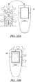
- FIGS. 2A and 2B illustrate generally respective views of an illustrative example of an apparatus, such as a hand-held apparatus 200, that can include an ultrasound transducer 136 and a display 114, such as including one or more portions of the example of FIG. 1 .
- the apparatus 200 can include one or more user inputs such as a first keypad 124, a trigger 108, or one or more other inputs (e.g., the display 114 may include a touch-screen or one or more soft-keys).
- the apparatus 200 can include one or more indicia to aid in alignment of the apparatus with a specified anatomical feature, location, or region.
- Such alignment indicia can include one or more displayed indicia presented on the display 114, or one or more fixed indicia located on a housing 126, such as a first indicium 130A, a second indicium 130B, or a third indicium 130C.
- One or more electrical ports can be included, such as for communication or recharging of a power source internal to the apparatus 200, such as including a port 140.
- model-based image reconstruction can be a significant consideration when implementing such a technique on hand-held or portable apparatus.
- such techniques can be implemented on a cell-phone class "Open Multimedia Application Platform” (OMAP) microprocessor, such as available from Texas Instruments Inc., Dallas, Texas, USA, to provide a real-time display of a bone location, shape, or orientation, or other information on a hand-held apparatus.
- OMAP Open Multimedia Application Platform
- Such model-based techniques can be enabled at lower computational cost such as using parameterized versions of echo data (e.g. bone depth estimates) rather than operating on the echo data itself.
- a dot product calculation can be the most computationally intensive step and can involve approximately 94 million floating point operations (MFLOPS).
- MFLOPS floating point operations
- a ultrasonic transducer apparatus can use an increased excitation voltage (e.g. from ⁇ 32 volts (V) to +/-128 V or more), such as including an active protection circuit, in order to provide 12 dB gain from increased excitation voltage and 6 dB gain from active protection, respectively, for a total of 18 dB improvement in round-trip signal-to-noise ratio (SNR).
- coded excitation can be implemented to yield further SNR gains of as much as 22 dB without requiring additional transmit pulses.
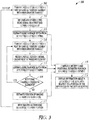
- FIG. 3 illustrates generally an illustrative example of an ultrasound imaging technique 300, such as can include apparatus and techniques that can involve independently operating, large, approximately circular ultrasound elements, such as including tracking one or more of the position or motion of a portion of the apparatus, and coupled to a processing circuit configured to one or more of compile echo data, compile position data, or provide image information for display of bone surfaces.
- an ultrasound imaging technique 300 such as can include apparatus and techniques that can involve independently operating, large, approximately circular ultrasound elements, such as including tracking one or more of the position or motion of a portion of the apparatus, and coupled to a processing circuit configured to one or more of compile echo data, compile position data, or provide image information for display of bone surfaces.
- One or more transducer elements can be positioned arbitrarily along two spatial dimensions, such as for obtaining ultrasound information for rendering intuitive images of bone surfaces.
- a transducer can include any device that can convert electrical energy to ultrasound energy - or vice versa.
- Examples of such transducers can include piezoelectric-based transducers or electrostatic-based transducers, or one or more other transducer types.
- the transducer element can be approximately circular or symmetrical such as having an area greater than 4 ⁇ 2 , where " ⁇ " can represent the wavelength of the ultrasound pulse.
- Approximately circular can refer to a transducer element shape that is polygonal such as with an aspect ratio approximately equal to 1 (e.g., a transducer having an active surface including a dimension in length that is approximately the same as a dimension in width, in the plane of the transducer active surface).
- the transducer element can include a square shape, or one or more other shapes such as having two or more axes of symmetry.
- the area criterion that the transducer area is greater than 4 ⁇ 2 can be derived from a square aperture assumption.
- a lateral resolution can be approximately equal to ⁇ z/L where "L" can represent the length of the aperture.
- a desired maximum resolution of 5 ⁇ can be specified at a shallowest maximum focal depth, "z," of 10 ⁇ .
- L should be greater than 2 ⁇ (e.g., (10 ⁇ / 5 ⁇ ) ⁇ ⁇ ) and therefore a corresponding transducer area can be 4 ⁇ 2 or greater to meet the constraint.
- Transducer element lengths e.g., an active surface of an element
- Transducer element sizes including a length or aperture having a dimension larger than 2 ⁇ (e.g., larger than existing generally-available ultrasound imaging systems) can be used such as to achieve a desired or specified resolution.
- Linear arrays are used in generally-available diagnostic medical ultrasound imaging.
- the present inventors have developed apparatus and techniques that can include the use of independently operating transducer elements (e.g., independently excited or receiving) including approximately circular elements. Independently operating elements that are approximately circular can be used to mitigate off-axis scattering artifacts that can corrupt bone images. Such mitigation or reduction can include 1) eliminating grating lobes or 2) providing resolution in the elevation and lateral dimensions that are similar (e.g., approximately equal), as opposed to generally-available 1-dimensional linear arrays that exhibit good azimuthal resolution, but poor elevational resolution.
- the element can be displaced (e.g., mechanically scanned) and the position of the element can be tracked before, during, or after such displacement Echo data can be used, such as to provide bone depth estimates corresponding to specified element positions, such as compiled to provide a rendering of an image.
- the position or orientation of individual elements can be determined such as using the position or orientation of an imagine assembly housing such elements, such as along with element positions or orientations relative to the apparatus.
- acoustic energy can be transmitted from an ultrasound transducer element.
- a first reflected echo can be received using the ultrasound transducer element.
- a bone surface depth can be estimated at least in part using the received echo.
- acoustic energy can be transmitted from a next ultrasound transducer (or the first ultrasound transducer can be repositioned either mechanically or via motion of the handheld assembly actuated by a user).
- a reflected echo can be received in response to the energy transmitted at 308.
- a bone surface depth can be estimate at least in part using the echo received at 314.
- the technique 300 can include respectively transmitting, receiving, and estimating as shown in 308, 314, and 316.
- a position of one or more ultrasound transducers can be estimated. If no additional ultrasound transducers are to be used, at 310, a bone depth estimate can be made and a position estimate can be made for one or more ultrasound transducers, and, at 312, information can be presented to a user about a location of the bone with respect to a portion of the imaging apparatus (e.g., the apparatus of FIG. 1 , FIG. 2 , or one or more other examples).
- the one or more ultrasound elements can be moved to a new position.
- Displacement of an element can be achieved via mechanically sweeping the element inside the apparatus or moving the element manually and estimating displacement using one or more of position or orientation sensing methods.
- tracking of transducer position to determine a position of the transducer beam can also include tracking orientation of the transducer, as both can affect the transducer beam.
- independent motion estimates can be obtained from one or more sensors included in an ultrasound imaging assembly, such as via obtaining information from a 1, 2 or 3-axis accelerometer, a gyroscope, an optical motion sensor (e.g., as used in optical finger navigation, for example by Avago Technology - avagotech.com), amongst other motion sensing technologies.
- motion of one or more of a transducer or the ultrasound imaging apparatus can be tracked using ultrasound echo data such as via template matching or decorrelation measurement.
- Such motion estimation can include aggregation of sensed information from one or more sensors, such as using information obtained from sensors having different sensing modalities (optical, acceleration, ultrasonic, or the like).
- different motion estimates determined from different sensors can be combined in a statistical manner to produce a more robust (e.g., less ambiguous or less erroneous) position estimate as compared to an estimate derived from an individual sensing modality.
- a median or other central tendency of received estimates can be used.
- a weighted average can be used where such a weighting can be derived from a measure of confidence or accuracy in an individual estimate (e.g. a ratio of a correlation "peak" to an RMS signal level).
- Two or more motion sensors can be positioned at separate locations on the imaging apparatus.
- the sensor information obtained from the two sensors can be combined to calculate the position or rotational orientation of the apparatus. This can be used to calculate in turn, the positions of the transducers as the apparatus is rotated or translated.
- the information from the ultrasound echoes or bone depth estimates as the apparatus moves around the spine can be combined to produce an image on a display screen.
- Such an image can be persistent, such as updated as the apparatus is moved across the skin, such as to maintain a location of the image relative to one or more actual anatomical feature locations, or to form a composite image.
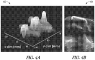
- FIG. 4A illustrates generally an illustrative example of a three-dimensional representation of an ex vivo spine 402
- FIG. 4B illustrates a corresponding illustrative example of a B-mode ultrasound image 404.
- a build up of a 3D bone surface can be determined, such as rendered on the display.
- Such an operating mode can produce an image equivalent to or mimicking one produced by a large array of transducers such as without the extra associated cost and complexity of such an array.
- Such a built-up display can be more intuitive than generally-available 3D echo-data rendering as such generally-available rendering contains speckle or other noise sources.
- surface samples e.g., 3D information sampled via ultrasound
- can be retired e.g., omitted from the display or the modeling process
- can be reduced in brightness or significance after a specified duration of time e.g., updating the display to incorporate temporally newer data and retire temporally older or "stale" data.
- the one or more ultrasound elements can include elements used for imaging, elements used for position sensing, or elements used for both.
- FIG. 3 An illustrative example of the techniques of FIG. 3 can include collecting echo data on 3 channels and translating the device with a motion stage of a 2D region of interest spanning approximately 5 cm x 10 cm.
- FIG. 4A includes 3D images obtained by processing echo data off-line using the imaging techniques described above.
- FIG. 4B illustrates an ultrasound B-mode image of the same spine in a similar imaging environment obtained using the Ultrasonix RP (Ultrasonix, Richmond, BC, Canada) with a 128-element linear array operated at 6.67 MHz center frequency.
- the present inventors have recognized, among other things, that the 3D image obtained from a 4-channel device as shown in the illustrative example of FIG. 4A can be more intuitive to the user and can exhibit much lower levels of noise and artifacts as compared to the image obtained using the apparatus of FIG. 4B .
- bone surfaces can be referred to as specular reflecting surfaces.
- specular reflecting surfaces can exhibit characteristics of specular and diffuse reflection. For example, almost all of the incident ultrasound energy insonifying the bone is reflected, but the roughness can cause some energy to be reflected at a variety of angles, which is not strictly specular reflecting behavior.
- specularity assumption can still be valid as the reflection from bone much closer to specular in nature than reflections from soft tissues, which are much weaker reflectors, and which in general appear to have random directivity, as compared to bone.
- ultrasound apparatus and techniques referring to imaging specular reflecting targets can be used to image targets that reflect the bulk of ultrasound energy directed at them, with some bulk directivity, but the targets can also include some diffusivity in their reflectiveness, reflecting some of the incident energy in a variety of directions.
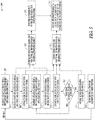
- FIG. 5 illustrates generally an illustrative example of an ultrasound technique 500 that can include using a model to estimate an anatomical target location, shape, or orientation.
- acoustic energy can be transmitted from an ultrasound transducer element.
- a first reflected echo can be received using the ultrasound transducer element
- a bone surface depth can be estimated at least in part using the received echo.
- acoustic energy can be transmitted from a next ultrasound transducer (or the first ultrasound transducer can be repositioned either mechanically or via motion of the handheld assembly actuated by a user).
- a reflected echo can be received in response to the energy transmitted at 516.
- a bone surface depth can be estimate at least in part using the echo received at 518.
- the technique 500 can include respectively transmitting, receiving, and estimating as shown in 516, 518, and 520.
- a position of one or more ultrasound transducers can be estimated.
- the one or more ultrasound elements can be moved to a new position.
- a position estimate can be made for one or more ultrasound transducers, and, at 510, a probabilistic fitting of echo data can be made to a statistical model.
- bone depth information and position estimates can be compiled corresponding to one or more ultrasound elements.
- information can be presented to a user about a location of the bone with respect to a portion of the imaging apparatus (e.g., the apparatus of FIG. 1 , FIG. 2 , or one or more other examples).
- apparatus and techniques can include using a 2D grid of ultrasound elements spaced at less than about 1/2 ⁇ pitch, such as including approximately circular subapertures, such as including tracking one or more of the position or motion of a beam axis corresponding to one or more subaperture positions, and coupled to a processor circuit configured to one or more of compile echo data, compile position data, or provide image information for display of bone surfaces.
- mitigation of off-axis artifacts can be achieved such as using a 2D array with less than 1/2 ⁇ pitch such as to reduce or eliminate grating lobes.
- One or more transducer elements in the array can include approximately circular subapertures such as to provide reasonable resolution in both axes parallel to the transducer element face.
- apparatus and techniques can include using the apparatus or techniques of the examples above or below, along with a bone surface location estimation determined such as by fitting the received echo data, or a parameters version of the received echo data, to a model.
- the present inventors have developed apparatus and techniques for rendering of bone surfaces from received ultrasound data such as using ultrasound information acquired as described in the examples above. Rather than (or in addition to) estimating an on-axis bone depth to construct a bone surface display, the present inventors have also developed apparatus and techniques that can include a reconstruction method that estimates bone surface location, position, or orientation, such as by performing a fitting of echo data, or a parameterized version of the echo data, to a model. Such echo data can be obtained using one or more transducer elements, information about the one or more element positions, or using subaperture techniques.
- a model-fitting scheme can be used to infer bone surface locations outside of the regions interrogated by the ultrasound beam.
- Such estimation techniques can be used in combination with a reduced repetition rate of ultrasound transmit/receive events as compared to generally-available B-mode imagine techniques, and thus such an estimation technique can provide a comparably higher frame update rate.
- Model-fitting techniques can provide bone surface location estimates with improved bias or variance as compared to generally-available image reconstruction techniques.
- Echo data obtained such as using the apparatus or techniques shown above and below can be fit to a parametric model.
- a model can include an anatomical feature of interest, such as a portion of the spinal anatomy (e.g., a "candidate" target).
- Such a model can be used to estimate a relative position, orientation, or size of the feature with respect to the apparatus.
- signal processing techniques such as including statistical techniques, can be used to fit the received echo data to a parameter model according to specified criteria (e.g., to reduce, enhance, maximize, minimize, or otherwise meet a specified criterion or metric).
- a maximum likelihood estimate of the spinal anatomy positional parameters can be determined such as using a priori information concerning the spinal anatomy, the geometry or arrangement of acoustic sensors, or the noise statistics of the system, among other information.
- Other metrics can be used to yield estimates, and such metrics may be selected based on computational burden or noise immunity depending on system specifications such as frame rate, noise environment, power longevity or size for a hand-held assembly, etc.
- a model-fitting approach can operate by fitting observed received echo data from one or more ultrasonic transmit-receive (TX/RX) events to a system model describing hypothetical (or previously-measured) received echoes from an array of different hypothetical bone surfaces (as discussed below).
- TX/RX ultrasonic transmit-receive
- Such a model-based image reconstruction technique can use or can be seeded with RF echoes from some or all potential TX/RX element combinations for the array, such as to adjust (e.g., increase) the dimensionality or information content of the system model (e.g., to refine the model).
- Defocused transducer elements can be used to give a large field of view such as using a relatively small number of transducer elements.
- defocusing can be achieved by using a convex transducer surface or by using a defocusing lens.
- a defocusing lens can be designed using the Lensmaker's Equation.
- a convex lens surface can be used when the lens material provides a sound velocity greater than that of sound in tissue (e.g. a lens material such as including TPX® distributed by Westlake Plastics).
- a concave lens surface can be used when the lens material provides a sound velocity lesser than that of sound tissue (e.g. a lens material such as including RTV560 distributed by Momentive).
- Defocusing can reduce SNR as compared to using focused transducers, but this effect can be mitigated at least in part by the +35dB relative brightness of bone echoes.
- image reconstruction can be performed, such as using a priori knowledge of spinal bone anatomy statistics and a signal model.
- a model e.g., a system model
- an image of bone surfaces can be inferred from a probabilistic model-fitting approach instead of traditional beamforming.
- a linear observation model can be used, such as used elsewhere for sound navigation and ranging (SONAR) or radar image reconstruction.
- N time samples can correspond to " M " received echoes for all or a subset of TX/RX combinations included in a transducer array
- P can represent a hypothetical collection of bone surfaces.
- a target vector, " y " of dim P x 1 can correspond to actual weightings applied to each column of S .
- a priori information such as the fact that individuals possess only one, unique spine, can be used to place constraints on the solution to EQN. (1). For example, only one non-zero entry in “ y " can be possible in reality. Thus, instead of finding the precise weightings of all entries in “ y ", the problem can be described as determining which entry of " y " is non-zero (e.g., which spine location, shape, and orientation, as modeled by the columns of S , is the most likely given observed data, " x ").
- Various techniques can be used, such as determining which combination of the hypothetical spines has the highest likelihood given the presently-obtained echo data and a priori knowledge of the likelihood of various spine models.
- the spine that has the highest weighting in the output can be determined as the spine representation to display, or can correspond to a specified spine representation to display.
- Such a determination can be made using a pseudoinverse operation, such as yielding the maximum likelihood solution given the model assumptions.
- the system can degenerate into a maximum normalized and weighted correlation (MNWC) approach.
- MNWC maximum normalized and weighted correlation
- the MNWC approach can include correlating the data set from the real spine with a set of hypothetical spines, normalized to remove effects due to some hypothetical spines' echoes being 'brighter' than others. For example, a weighting can be applied to a correlation, to take into account an a priori probability of a particular hypothetical spine, as some hypothetical spines can be more likely candidates than others, such as representing a maximum-likelihood technique.
- Simulation can be used to assess the bias and variance of a model-based technique, such MNWC model-fitting technique above.
- the human spine geometry can be shifted laterally or in the depth dimension, or the amount of additive electrical noise can be varied.
- Simulated echo information from such scenarios can be obtained using FIELD II software.
- Bone surface estimates can be determined using the MNWC model-fitting approach, for a variety of lateral offsets, depths, and SNRs.
- Probabilistic model-fitting technique can be enhanced in a number of ways. If the variable " x " is formed from parameterized, or pre-processed, echo data such as a vector of the estimated bone surface depths for each TX/RX event, computation complexity can be reduced as compared to using raw or unparameterized echo information.
- Another enhancement can include modifying the system model to include a series of hypothetical spine sub-units rather than hypothetical whole spines.
- Such a sub-unit approach can provide estimates for spine anatomy as a combination of several different spine sub-units.
- the spine sub-units can include the spinal bone associated with a single vertebra, or other, smaller sub-units such as the spinous processes, or portions of the transverse processes that extend laterally from the spine, or one or more other sub-unit configurations.
- a sub-unit modeling approach can yield more complicated statistical properties, which can be used to increase the accuracy of the spine estimate.
- One such statistical property can include mutual exclusivity between sub-units that occupy the same three dimensional space.
- Another statistical property can include the spacing between adjacent spinal sub-units; for example, inter-vertebral distance has a statistical distribution.
- An image representing a bone surface can be rendered via a superimposition or other combination of model-fitting and other bone surface location estimation techniques. For instance, bone surface location, shape, or orientation can be estimated from each echo individually, and then also from a model-fitting approach using a set of echo data, or using a parametric model of echo data. Color or other indicia can be used to identify image information corresponding to one or more construction techniques. For example, using different colors can help to illustrate which parts of a displayed image correspond to renderings of ultrasound echoes as compared to enhanced images inferred or otherwise constructed using a model-fitting technique.
- estimation techniques can be employed that combine bone depth estimates acquired from received echoes on an individual basis with model-based iterative probabilistic statistical signal processing techniques.
- one approach can include using a priori probability information to produce initial estimates of the spinal sub-units using a subset of the information available, such as using these estimates to produce an updated probability based on the estimates.
- Such updated probabilities information can be passed around the model as 'belief' messages, in order to re-compute the answer to the problem iteratively.
- Such techniques are generally referred to as "loopy belief propagation," and have been shown to converge in practical situations, such as producing better estimates at lower computational cost than other estimation techniques.
- such a technique can include:
- the original echo data can be converted to bone surface depth estimates, before entering the loopy belief propagation stage. It is also possible to use information from the current step of the iterative spine sub-unit estimation to refine the estimation of the bone reflection positions, as the estimation of bone surface reflection position is itself a stochastic operation. For example, if a spinal sub-unit is postulated by the sub-unit iterative estimator with high likelihood, then bone surface positions that would likely arise from this sub-unit are more likely. Thus, probability information can propagate iteratively between the echo data domain and the bone surface domain. Loopy belief propagation can be used to exploit the statistical properties of spine topology and ultrasound imaging physics, giving improved accuracy in spine position detection, and enhanced robustness to noise sources.
- FIG. 6 illustrates generally an illustrative example of an ultrasound technique 600 that can include using a model to estimate an anatomical target location, shape, or orientation.
- "S" can represent the spine sub-unit probabilities.
- "S” can be a vector of the existence probabilities of various spine sub-units, which are hypothetical spine fragments, for example pieces of the spinous processes or transverse processes.
- the sub-units can form a library of parts that can be used to form any realistic spine. Therefore, this vector can provide a readout of the estimation technique.
- B can represent bone surface position estimates.
- B can be a set of position estimates for the depth of bone surface at various positions in the X-Y plane parallel to the device surface applied to the skin.
- the bone surface estimate may consist of a Gaussian probability distribution, such as parameterized fully by a mean and variance.
- the set of bone position estimates, "B" can provide another readout of the estimation technique.
- "X" can represent a noiseless RF signal that would be expected from a transmit-receive event located at a specified X-Y location, containing the echo data from a bone surface, if such a bone surface were present below the transducer.
- the noiseless RF echo can arise from the bone surfaces "B,” and can also be modified by the bone roughness at the corresponding bone surface element, as indicated in FIG. 6 .
- "Y" can represent the measured RF with noise, such as obtained from a transmit-receive event at a specific location in the X-Y plane. This can be equivalent to the noiseless RF, "X,” but with added electronic noise and speckle artifact.
- the electronic and speckle "noise” have statistical properties, shown as inputs to the Y variable.
- the overall problem statement can be to estimate "S" or "B,” given the measured RF signals and the properties of the system model comprising how spine sub-units in "S" map to bone surfaces in "B,” and how these bone surfaces map to RF signals with noise effects.
- Such a problem can be solved, such as in one step, to produce a maximum likelihood estimate of "S” given "Y.”
- Such a single-step solution can be computationally inefficient, and some of the system model may involve non-linear mappings, making solution difficult.
- the overall problem can be broken down into two sub-problems, providing a simpler and more computationally efficient iterative belief propagation approach:
- a technique for iterating such an estimate can include:
- the iterative technique described above can use information about a probabilistic spine topology model that relates the probabilities of different spine sub-units to each other, and a spine sub-unit topology that relates different spine sub-units to the corresponding bone surfaces that are produced. It is believed possible to encode the probabilistic spine topology as one or more covariance matrices, describing the reinforcement, mutual exclusiveness and other probabilistic relations between the spine units. However, a procedural process can also be used to encode the probability dependence between sub-units, such as incorporating nonlinear elements. Nonlinearity can arise if the probabilistic spine topology incorporates both positive reinforcement elements and negative reinforcement elements.
- the spine sub-unit topology can include a mapping between the different spine sub-units and the corresponding bone surface positions. This can be a deterministic bidirectional mapping.
- a single sub-unit corresponds to a location in space that can map to a series of bone surface elements with distinct positions in the X-Y plane and a depth in the Z dimension.
- each bone surface element in B can correspond to a probability distribution parameterized by a mean and variance.
- a marginal probability of a sub-unit can be updated using information about its existing probability and the probability information about its constituent bone surface elements in B.
- its constituent bone surface element probability parameters can be updated, such as incorporating their expected positions given the sub-unit, and the sub-unit's probability of existence.
- An output of the iterative technique can be a set of spinal sub-unit likelihoods, plus a set of estimates of bone surface positions.
- an image reconstruction for display can be formed using either one of these variables, or a combination of the two. Incorporation of the probabilistic spine topology can increase the accuracy and robustness of the final image formation as compared to generally-available B-mode imaging techniques.
- Illustrative examples that can include determining and presenting a two-dimensional or three-dimensional representation of a target
- Apparatus and techniques can include rendering of bone surfaces, such as using portions of one or more of the examples discussed above or below, to provide a low-cost, portable, and intuitive-to-use apparatus that can provide higher success rates than a "blind approach” technique, and can do so at lower cost than using fluoroscopic or generally-available ultrasound techniques.
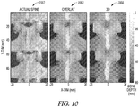
- FIG. 7A illustrates generally an illustrative example of an animal spine 702
- FIG. 7B illustrates generally an illustrative example of a two-dimensional representation 704 of the spine of FIG. 7A
- FIG. 7C illustrates generally a corresponding ultrasound image 706 of the animal spine obtained using a commercially-available ultrasound system.
- an apparatus can be configured to provide pulse-echo ultrasound imaging such as using four channels and display data in real-time with automated bone depth detection, such as including a liquid-crystal display (LCD) touch-screen and Google Android user interface (or one or more other operating systems, interfaces, or displays).
- a liquid-crystal display (LCD) touch-screen and Google Android user interface or one or more other operating systems, interfaces, or displays.
- such an apparatus e.g., as shown in FIGS. 2A and 2B , or in other examples
- a commercially-available Ultrasonix RP system can each be used to image an animal spine in a water tank across a 90 mm x 50 mm 2D plane to produce 3D volume image data.
- Such experimental ex vivo imaging can be rendered in 2D or 3D, such as the two dimensional representation 704 included in the example of FIG. 7B .
- images in FIGS. 7B and FIG. 7C generally demonstrate good agreement with simulations depicted in the illustrative example of FIG. 9 where elimination of grating lobes using a piston transducer generally results in lower levels of imaging artifact.
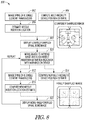
- FIG. 8 illustrates generally an illustrative example of an ultrasound imaging technique 800 that can be used to render an image of an anatomical target, such as bone, such as with automated determination and identification to a user of a needle insertion site (e.g., an interlaminar space).
- an ultrasound imaging technique 800 can be used to render an image of an anatomical target, such as bone, such as with automated determination and identification to a user of a needle insertion site (e.g., an interlaminar space).
- images of spinal bone anatomy can be rendered using a low number of large (i.e. > 2 ⁇ diameter), circular, single-element transducers such as shown in FIG. 8 at 802 or 812, and using a multi-modality device positional estimation technique shown in FIG. 8 at 804 or 814.
- the technique of FIG. 8 can provide several advantages over generally-available techniques.
- the large, circular transducer elements can mitigate off-axis specular reflection artifacts that occur in generally-available ultrasound due to grating lobes and broad focus in the elevation dimension that are characteristic of linear array transducers.
- the transducer geometry can, at least in part, mitigate artifacts that are prevalent from imaging of specular reflecting surfaces.
- the combination of single-element transducers with multi-modality position sensing technology can be lower cost than generally-available ultrasound apparatus, or lower cost and less complex than a mechanically-scanned transducer.
- an image display approach can be used to automatically determine and identify to a user an appropriate needle insertion site such as by fitting underlying ultrasound echo data to a spinal bone model. Such approaches help to simplify user interpretation of the underlying ultrasound data, and reduce or eliminate the need for specialized training in ultrasound image interpretation.
- a predominantly specular target such as a spine
- a multi-modality position estimate can be determined (e.g., using information about received ultrasound energy, and information obtained from one or more other sensors or techniques, such as optical, magnetic, or acoustic information).
- an initial, coarsely sampled spinal bone image is shown such as after the first ultrasound A-lines are collected.
- the device e.g., a handheld apparatus
- the spine can be imaged from the new position of the apparatus.
- a new multi-modality position estimate can be determined.
- one or more displayed indicia can be updated, such as an estimate of a needle insertion location.
- a user e.g., a physician
- manipulate the device such as by translating it across the imaging area to improve image resolution until red needle insertion lines (e.g., a displayed indicium) are aligned with one or more device case markings (e.g., one or more fixed indicia), such as shown at 818, or using one or more other indicia.
- the user can then mark the patient's skin at locations adjacent to the device case markings, such as similarly to markings that can be provided in general practice for ultrasound guidance of central neuroaxial anesthesia.
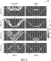
- FIG. 9 illustrates generally an illustrative example of acoustic field amplitudes 900 that can be obtained via simulation.
- ultrasound imaging simulations can be performed using FIELD II software, such as to quantify off-axis reflection artifacts from a piston transducer having a 3/8" diameter, 5MHz center frequency, with 5 cm focus, and as compared to a simulated Ultrasonix RP L14-5 linear array at 5 MHz center frequency, 300 micron pitch, and 5 cm focus, the array obtainable from Ultrasonix, Richmond, BC, Canada.
- Specular reflection surfaces can be simulated such as by placing targets at uniformly spaced intervals along the simulated specular reflecting surface. On axis and off-axis surfaces can be simulated at varied imaging depths and angles.
- a focused piston transducer can suppress grating lobes and exhibit tighter focus in the elevation dimension. Consequently, use of such a piston geometry can provide less image artifact from off-axis specular reflections as compared with the linear array to yield an on-axis to off-axis reflection amplitude contrast improvement of more than 10 dB. In general, performance deteriorates with the linear array at higher frequencies where grating lobes can become more pronounced.
- FIG. 9 illustrates generally an illustrative example of an effect of grating lobes from a linear array on the ratio of on-axis to off-axis reflection energy. Simulations can be performed in FIELD II as described above using the L14-5 simulated linear array operating at 10 MHz and the above-mentioned piston transducer operating at 10 MHz such as including both transducers focused at 3 cm.
- the first and second columns of images in FIG. 9 illustrate generally the propagation of the acoustic waves against on-axis and off-axis specular reflecting surfaces at various times.
- acoustic energy outside of the main lobe of the acoustic beam can be larger in the linear array than in the piston transducer due to grating lobes.
- Coherent reflections of grating lobe energy against off-axis specular surfaces can thus result in a significant increase off-axis reflection signal when using the linear array compared with the piston transducer.
- the present inventors have recognized that a high on-axis to off-axis reflection ratio is preferred for imaging as such a ratio is indicative of lower levels of image artifact. It is believed that grating lobes or insufficiently tight focus in the elevation dimension can be eliminated or reduced such as by using a piston transducer such as to image bone using ultrasound with substantially mitigated artifact as compared to using generally available linear arrays.
- FIG. 10 illustrates generally an illustrative example of a photograph of an animal spine 1002, a three-dimensional representation of the spine 1006 (e.g., such as determined using one or more approaches above or below, such as can be presented to a user), and an overlay 1004 showing the animal spine photograph and the three-dimensional representation.
- the image rendering of FIG. 10C generally illustrates high correlation with an optical image of the spinal bone as shown in FIG. 10A, and an overlay of such a rendering and such an optical image is shown for comparison in FIG. 10B.
- FIG. 11 illustrates generally an illustrative example of an ultrasound imaging technique 1100 that can include rendering of bone surfaces from received ultrasound data using one or more portions of the techniques described in the examples above or below and that can include a technique for reconstructing ultrasound images that can be referred to as principal harmonic imaging (PHI).
- PHI principal harmonic imaging
- a portable medical ultrasound-based bone imaging system with 3D imaging capabilities can be provided at lower cost (e.g., ⁇ $1K cost-of-goods-sold (COGS)) and in a more compact form than generally-available X-Ray or generally-available ultrasound equipment.
- COGS cost-of-goods-sold
- Such a portable apparatus can be configured to perform techniques such as principal harmonic imaging (PHI).
- PHI principal harmonic imaging
- the present inventors have recognized, among other things, that PHI can, at least in part, reduce or suppress image artifacts, improve image resolution, or enhance delineation of bone surfaces from surrounding tissue and noise as compared with generally-available ultrasound imaging at the fundamental frequency.
- Apparatus such as configured to provide bone surface imaging using a PHI technique could shift clinical practice and assist in assessment of bone trauma, such as in ED triage upon patient arrival.
- the present invention could increase the use and efficacy of medical imaging for triage of patients with bone trauma either at the site of injury or immediately upon presentation to the ED.
- Triage of patients with bone trauma has been shown to decrease waiting times, which in turn, improves patient recovery times, decreases hospital stays, and decreases mortality rates. Because the elderly are more likely to fracture bones and more likely to require invasive treatment as a result of fracture, the elderly segment of the population could benefit most from triage using portable, low-cost bone surface imagine apparatus and techniques.
- principal harmonic imaging (PHI) imaging can be used to reconstruct ultrasound images.
- PHI reconstruction technique can be implemented to render ultrasound images, such as including apparatus, such as a hand-held apparatus, configured to one or more of:
- PHI can be used for 2D or 3D image reconstruction of a target (e.g., bone) as described in the examples above.
- PHI can be applied to received echo data, such as the received echo data, to improve a position estimate of a target, such as a bone surface.
- PHI filtering of the data can take place upon receiving the echo data on an ultrasound transducer, such as prior to estimating a bone depth or other information (e.g., one or more of a location, shape, or orientation).
- the present inventors have also recognized, among other things, that 2D ultrasound images can be rendered using PHI as a replacement for tissue harmonic imaging (THI).
- THI tissue harmonic imaging
- PHI can be used to image bone or any other soft tissue anatomy such as heart, blood vessel, breast, liver, kidney, for example.
- real or complex echo data can be used with PHI, and a windowed region of echo data can range any number of samples > 1.
- singular spectrum analysis SSA
- SSA singular spectrum analysis
- the Hankel matrix can be mean reduced, and PCs can be computed from the mean-reduced Hankel matrix.
- a Hankel matrix can represent a matrix with constant skew diagonals.
- PCs can be computed via a singular value decomposition (SVD) of the Hankel matrix, an eigenvalue decomposition of the covariance or autocorrelation matrix of the mean-reduced Hankel matrix, or using one or more other techniques of computing the PCs of the mean-reduced Hankel matrix.
- SVD singular value decomposition
- any number of pixels of interest from any number of echo samples can be used in PHI.
- the original data can be projected onto any number of PCs.
- only the 2nd PC is retained as it is most likely to describe energy in the 1st harmonic when using a window length of a half of a wavelength.
- PCs can be determined from a mean reduced Hankel matrix, and thus, the mean vector can be determined such as by taking the mean of columns in H and adding such means to each row in Y after determining Y via equation (2).
- PCs may be selected adaptively from characteristics of the PCs such as the singular value spectrum properties or frequency properties of the PCs.
- adaptive selection of PCs can include: the original data is projected onto all PCs that include frequency content in the 1st harmonic band above a specified threshold value.
- An output matrix can be formed, such as including elements determined using information from one or more reconstructed matrices, Y , such as corresponding to one or more pixels of interest in an image frame to be displayed.
- any form of bandpass filter can be used such as a filter spanning the fundamental frequency, 1st harmonic, or any combination of frequencies, such as applied to the output matrix (e.g., applied to one or more columns of the output matrix).
- bandpass (or other) filtering can be applied to the output matrix and then such a filtered output can be envelope detected, log-compressed, or otherwise conditioned such as for display to a user.
- An image display method can be used to render an ultrasound image from echo data processed with the PHI technique.
- PHI processed echo data can be envelope detected such as via computing the absolute value of the complex representation of such echo data, then log compressing the envelope-detected data, such as for display using a linear or non-linear gray scale mapping.
- PHI can be compared to tissue harmonic imaging (THI); however, PHI can use a principal component analysis (PCA) technique to separate signal components at the harmonic frequencies.
- PCA principal component analysis
- PHI exhibits advantages over THI that can include: signal components with overlapping frequencies can be separated (e.g., information corresponding to tissue can be separated from information corresponding to bone structure), in-band noise can be separated from signal, and the PHI technique can be adaptive to local spatial variations in the data.
- PHI can provide similar resolution improvements as can be provided by THI, such as compared with imaging at the fundamental frequency, but PHI can provide better reverberation reduction, sharper contrast of bone structures, or lower noise than THI or imaging at the fundamental frequency.
- PHI mechanically scanned, circular, single element transducers with large diameter (i.e. > 2 wavelengths) can be used.
- PHI can be used on received echo data from any transducer geometry including, for example, a linear array, a 1.5D array, a 1.75D array, a 2D array, an annular array, or one or more other arrays.
- Ultrasound targets such as bone can be imaged using PHI operating on received echo data such as obtained from large, approximately circular transducers as described in examples.
- received echo data such as obtained from large, approximately circular transducers as described in examples.
- single element transducers can mitigate various artifacts in bone imaging. While 2D arrays with ⁇ 1 ⁇ 2 wavelength pitch would also mitigate off-axis reflection artifacts, such systems can be expensive and are generally not capable of being implemented in hand-held apparatus.
- use of relatively large transducers can be performed in combination with one or more of multi-modality position estimation and PHI, such as in a hand-held assembly.
- ultrasound images can be rendered using PHI as described above and illustrated in the example of FIGS. 12A through 12F .
- FIG. 12A illustrates generally an illustrative example of an ultrasound image 1202 of a phantom obtained using a fundamental frequency technique
- FIG. 12B illustrates generally an illustrative example of an ultrasound image 1204 of the phantom obtained using a tissue-harmonic-imaging technique
- FIG. 12C illustrates generally an illustrative example of an ultrasound image 1206 of the phantom obtained using a principal-harmonic-imaging technique.
- FIG. 12D illustrates generally an illustrative example of an ultrasound image 1208 of an in vivo elbow joint obtained using a fundamental frequency technique
- FIG. 12E illustrates generally an illustrative example of an ultrasound image 1210 of the in vivo elbow joint obtained using a tissue-harmonic-imaging technique
- FIG. 12F illustrates generally an illustrative example of an ultrasound image of the in vivo elbow joint obtained using a principal-harmonic-imaging technique 1212.
- raw radiofrequency ultrasound echo data can be acquired from an Ultrasonix RP scanner and an L14-5 linear array transducer when imaging an RMI 404GS phantom (as shown in the illustrative examples of FIGS. 12A through 12C ) or an in vivo elbow joint (as illustrated in the illustrative examples of FIGS. 12D through 12F ).
- the center frequency was 4 MHz for the Ultrasonix RP scanner.
- PHI, THI, and fundamental image reconstruction techniques can be compared.
- PHI can provide > 3 dB improvement in cystic contrast-to-noise ratio (CNR) over THI with greatly enhanced detection of wire targets located at about 45 mm depth. Similar trends can observed in in vivo images FIGS. 12D through 12F where sharper contrast and reduced clutter and noise can be observed for bone structures where images can be reconstructed with PHI. Compared with imaging at the fundamental frequency, both PHI and THI can yield comparable gains in resolution.
- CNR cystic contrast-to-noise ratio
- PHI can additionally reduce reverberation clutter artifact, improve resolution, and can provide sharper delineation of bone surfaces
- piston transducer geometries can be demonstrated to additionally reduce off-axis specular reflection artifact
- a combination of large, approximately circular transducer geometry and PHI, as illustrated in examples above, can provide improved bone imaging with ultrasound as compared to using an array, using THI, or using fundamental frequency imaging.
- a multi-modality position sensing approach can be used in combination with one or more of the techniques or apparatus discussed above.
- an approach can combine estimates from one or more of optical finger navigation (OFN) and ultrasonic position estimates. Such combined estimates can be used to yield a new estimate with lower bias and variance such as via determining a maximum likelihood estimate assuming independently Gaussian-distributed errors.
- custom electronics can for two OFN sensors that can be integrated into apparatus as apparatus shown in FIGS 2A and 2B .
- the bias and standard deviation from a multi-modality position sensing technique using OFN and ultrasound measurements can provide bias and standard deviation at 0.037 mm and 0.189 mm respectively, such as for 2 mm translations.
- an optical camera can used with or without OFN and ultrasound measurements to yield a position estimate.
- One or more of illumination or filtering can be provided to preferentially image the target area with specific light wavelengths.
- One or more of the apparatus and techniques described in examples above can include a mechanically scanned piston transducer (e.g., a transducer configured with a 3/8" diameter, a 5 MHz center operating frequency, and a 5 cm focal depth, or using one or more other center frequencies or focal depths), such as a transducer obtained from Interson, Desion, California, USA.
- a mechanically scanned piston transducer e.g., a transducer configured with a 3/8" diameter, a 5 MHz center operating frequency, and a 5 cm focal depth, or using one or more other center frequencies or focal depths
- An illustrative example of motion estimation that can include an echo decorrelation technique
- Speckle tracking and decorrelation-based methods can be used to track motion using ultrasound data, for azimuthal and elevational motion respectively.
- the point spread function PSF
- a sector scan transducer can provide two or more differently-angled scan beams (e.g., to provide ultrasonic energy in at least two directions), such as each having a different angle with respect to a direction of tissue (or other target) motion.
- a complex RF decorrelation can vary with the angle between the scan beam and the tissue motion direction.
- the present inventors have recognized, among other things, that the set of complex RF decorrelation data from respective scan beams in respective directions can be used to infer the direction and magnitude of tissue (or other target) motion relative to the imaging apparatus, such as along with transducer orientation.
- a Bayesian probabilistic estimator can be constructed, such as having the capability to estimate motion in-plane or out-of-plane, such as individually or contemporaneously, such as along with transducer orientation.
- Other applications include estimation of dynamic rotations, from such complex decorrelation data.
- ultrasound echo information can be used to track azimuthal and elevational (e.g., out-of-plane) motion, such as using speckle tracking and speckle decorrelation methods, respectively.
- Tracking axial motion using RF data can provide higher resolution than for lateral motion, such as due to the higher spatial frequency in the axial dimension, a smaller speckle size for received complex echo RF data in this dimension, and an ability to use time-delay estimators that can closely approach the Cramer-Rao Lower Bound (CRLB).
- CRLB Cramer-Rao Lower Bound
- Tissue motion can be decomposed into orthogonal axial and lateral components relative to each of the sector scan A-lines (e.g., such "sectors” corresponding to respective directions of transmission or receiving of ultrasound energy). Therefore, when in-phase/quadrature (IQ) signals are used, the complex inter-frame correlation data for each A-line can include information from which one or more of the axial and lateral components of motion can be estimated.
- IQ in-phase/quadrature
- a probabilistic, Bayesian maximum likelihood estimator of motion and orientation can use the angular spread of sector-scanned A-lines.
- sector-scan ultrasound systems have PSFs that are rotated between different A-lines.
- this changes the correlation curves for both lateral and axial motion due to geometric projection.
- a transducer motion vector with elevational or lateral components will make a different angle, " ⁇ i ,” with each of the angled A-lines, providing a diverse set of complex decorrelation curves, as a function of motion, transducer orientation, and A-line geometry.
- a Bayesian maximum likelihood estimator for the motion vector and transducer orientation can be formed. In this manner, an absolute orientation of the transducer can be detected during motion, rather than just a change in orientation.
- FIG. 13 illustrates generally an illustrative example of angled A-lines (B) and non-angled A-lines (A) that can be used for estimation of translation or orientation using an echo decorrelation motion estimation technique.
- a lateral shift complex decorrelation curve can be represented by an autocorrelation of a PSF, such as an approximately Gaussian-shaped representation.
- a decorrelation can be complex.
- phase can be linear with shift for small angles, as indicated by the phase factors discussed above.
- Axial and lateral envelopes can be geometrically projected on a shift direction.
- FIG. 14A illustrates generally an illustrative example of a parametric curve fit 1402 using simulated A-line information in an echo decorrelation motion estimation technique
- FIG. 14B illustrates generally an illustrative example of a parametric curve fit 1404 using experimentally-obtained A-line information in an echo decorrelation motion estimate technique.
- a mechanical, 60-degree sector-scanned, piston transducer (Interson, Desion, CA) was simulated and used to capture complex (I/Q) experimental data while translated over a tissue mimicking phantom.
- Simulation in FIELD II were used to characterize variations in complex correlation curves with different motion vectors and transducer orientations.
- Bayes' theorem can be used to relate the conditional probability of a motion vector, " m ,” such as given a set of observed normalized complex correlations, " r ,” such as for 50-pixel segments of 256 A-lines at a range of six depths, as in EQN. (3).
- the motion vector m can be defined as a scalar displacement, "
- the evidence probability that can be represented by "P( r )" can be constant for all values of " m ,” the denominator can be replaced with a proportionality operator in the posterior probability as in EQN. (5).
- the maximization of EQN. (6) can be converted to minimization of a Euclidean distance measure (e.g., a log-likelihood), which can be a computationally simpler approach.
- a Euclidean distance measure e.g., a log-likelihood
- a model can be derived of the complex correlation that can be represented by " r i,j ,” such as for a segment of 50 pixels from the A-line acquired at the 'i'-th angle, at depth 'j," for a translation “ s “ making an angle " ⁇ I " with the A-line axial direction vector, shown in EQN. (7).
- the depth-dependent elements "a j ( ⁇ i )” and “b j " can be a function and a depth-related constant respectively, with "a j ( ⁇ i )” represented as in EQN.
- FIGS. 15A through 15C illustrate generally these experimentally-determined illustrative examples.
- FIG. 15A illustrates generally an illustrative of an azimuthal shift motion estimation determined using various techniques
- FIG. 15B illustrates generally an illustrative example of an elevation shift motion estimation determined using various techniques
- FIG. 15C illustrates generally a rotational shift estimation determined using various techniques.
- azimuthal motion was estimated using a model with a fixed (and erroneous by 5 degrees) rotation about the elevational axis. Poor performance in this case (denoted by triangles) indicates that rotational degrees of freedom can significantly increase estimation robustness.
- FIG. 16 illustrates generally an illustrative example of a needle-guide technique 1600 that can include using a hand-held ultrasound imaging apparatus, such as including an optical sensor.
- a two-dimensional B-mode image can be obtained such as using a piston transducer.
- a position of the ultrasound imaging apparatus can be estimated using a multi-mode estimate including information obtained from received ultrasound echoes and information obtained via an optical sensor (e.g., a complementary metal-oxide-semiconductor (CMOS) image sensor, a charge-coupled device (CCD), or using one or more other optical sensors).
- an active shape model technique can be used to delineate a bone surface.
- a coarsely-sample three-dimensional bone image can be presented to a user.
- an ultrasonic transducer or an apparatus including the transducer can be translated (e.g., a transducer can be mechanical scanned or a fixed transducer can be translated via movement of the assembly, such as movement of a handheld assembly over tissue).
- a new two-dimensional B-mode image can be obtained such as using a piston transducer at the new location.
- a new position of the ultrasound imaging apparatus can be estimated using a multi-mode estimate.
- a bone surface can be estimated using an active shape model technique.
- a needle insertion location can be estimated.
- a more finely sampled three-dimensional bone image can be presented to the user, including an estimate of the needle insertion location (e.g., a displayed indicium such as a cross-hairs can be presented to the user).
- the technique 1600 can include returning to 1610 and the apparatus can be translated (e.g., moved slightly) by a user.
- a needle can be inserted at a specified location, such as along or nearby a tick mark as shown in the illustrative example of FIG. 16 .
- a statistical signal processing model-fitting strategy can be used, and can be referred to as an "active shape model.”
- an active shape model can be used to automatically segment the surface of a spinal bone from a series of obtained 2D images.
- the segmented bone surface profile along with the multi-modality position estimates can be used together to build up a three-dimensional image of the bone.
- FIG. 17 illustrates generally an illustrative example 1700 of a shape-modeling technique.
- v can represent the segmentation solution
- " B ( v )" can represent values of an edge detection image at the segmentation solution location
- " m " can represent a solution from a statistical model fitting applied to vector v (or a filtered version of v as in FIG. 18 )
- C 1 and C 2 can be constants.
- a computer aided design can be used as a basis for the model, such as to provide a candidate "target," such as at least a portion of a spine.
- a number of spine surface profiles can be compiled, such as corresponding to respective orientations of at least a portion of the spine.
- a filtering operation can be performed on the respective profiles, such as including low-pass filtering.
- one or more profiles can be aligned or scaled, such as to a common magnitude (e.g., a normalization of the profiles can be performed).
- respective landmark points can be identified, and corresponding (x,y) coordinates for respective landmarks can be determined to provide respective resampled profiles.
- such resampled profiles obtained at 1710 can be arranged into a matrix, that can be represented by " X .”
- a principal components analysis can be performed, such as to create a statistical shape model.
- a shape model can include a "mean" spine shape
- such a shape model can include respective eigenvectors
- at 1720 such as shape model can include respective eigenvalues.
- a subgroup of eigenvectors can be retained, such as corresponding to the largest associated eigenvalues.
- FIG. 18 illustrates generally an illustrative example of a shape-modeling technique 1800.
- ultrasound imaging information can be acquired, and at 1804, an edge detection can be performed on an acquired image.
- shape modeling techniques can have limitations such as that (1), they may not generally be automated; (2) they may assume that the shape of interest is always in the field of view; (3) they may not utilize prior information; (4) training sets may be constructed from a low number of manually segmented images; and (5) they generally may not be used as one of a plurality of factors in an energy function, which can be iteratively maximized or minimized to find a segmented profile.
- limitation (1) can be addressed, such as in FIG. 18 by fully automating the initialization of the segmentation solution, which can be performed at 1804, 1806, 1808, or 1810.
- Limitation (2) can be addressed, for example, by using 1808.
- an additional row can added to the image matrix, which can represent the location of "no bone" in the image. If no bone is in the image or if the model fitting vector does not fit well to the proposed segmentation vector, then values in a matrix H can be reduced, and the solution can converge to locations along the artificially created bottom row the matrix.
- Matrix H can represent the edge detected image B but with a row added to the end, which can be set to a value represented by " ⁇ 1 .”
- the method need not be forced to "find” or segment a bone structure when there is none in the image or if the entire bone is not in the field of view.
- a filtering operation can be performed on the segmentation profile solution, " v ,”
- (x,y) coordinates e.g., depth and lateral positions
- SSM statistical shape model
- respective spine segment vectors, " x " can be statistically fitted to yield a statistical shape model fitting, " m .”
- an error matrix can be computed, such as using a minimum Euclidean distance between the (x,y) coordinates for respective entries in " x .”
- respective rows in H can be updated such as by penalizing locations that are not near the model fitting and reinforcing locations close to the model fitting.
- the technique can return to 1810. Otherwise, one or more of " v ,” " b ,” or " m ,” can be output at 1824.
- Limitation (4) can be addressed, for example, by using a CAD model as discussed in relation to the example of FIG. 17 .
- Limitation (3) can be addressed, for example, such as by incorporating prior information into the technique illustrated in FIG. 18 , such as shown in FIG. 19 , which illustrates generally an illustrative example of a shape-modeling technique 1900.
- ultrasound imaging information can be acquired, and at 1904, an edge detection can be performed on an acquired image.
- a value can be determined as a multiple of a standard deviation of a speckle region.
- an additional row can added to the image matrix including the value determined at 1906, which can represent the location of "no bone" in the image.
- an error can be computed such as via "pre-weighting" H based on the segmentation results from previous images.
- the C k values can be equal for all k at 1912 or they can depend on the distance or time from the current image in which the prior data was acquired. Generally, 1910 and 1912 bias segmentation results toward results achieved from previous images.
- a filtering operation can be performed on the segmentation profile solution, " v ,”
- (x,y) coordinates e.g., a depth and a lateral position
- SSM statistical shape model
- respective spine segment vectors, " x " can be statistically fitted to yield a statistical shape model fitting, " m .”
- an error matrix can be computed, such as using a minimum Euclidean distance between the (x,y) coordinates for respective entries in " x .”
- respective rows in H can be updated such as by penalizing locations that are not near the model fitting and reinforcing locations close to the model fitting.
- the technique can return to 1914. Otherwise, one or more of " v ,” " b ,” or " m ,” can be output at 1928.
- Limitation (5) can be addressed such using the techniques of FIGS. 18 or 19 , such as including iteratively minimizing or maximizing an error function.
- such techniques can iteratively finds a profile that can minimize error compared with the shape model and maximizes an edge strength such as shown in EQN. (9), such as shown at 1820 or 1924, including an incorporation of an error, " E ,” such as with an edge strength that can be represented by " H .”
- needle insertion site identification that can include an ultrasound imaging technique
- FIGS. 20A through 20G illustrate generally a technique that can include identifying a needle insertion site such as for use in an epidural anesthesia procedure.
- an ultrasound imaging apparatus 100 can be coupled to a patient's skin, such as in proximity to a lumbar spine region.
- the ultrasound imaging apparatus 100 can be translated along a surface of the patient's skin, such as to "build up" a three-dimensional representation of the spine.
- a cross hairs or other displayed indicia presented to the user on the handheld apparatus 100 can be aligned to one or more of a marking instrument guide or a needle guide located on the housing of the apparatus.
- FIG. 20A an ultrasound imaging apparatus 100 can be coupled to a patient's skin, such as in proximity to a lumbar spine region.
- the ultrasound imaging apparatus 100 can be translated along a surface of the patient's skin, such as to "build up" a three-dimensional representation of the spine.
- a cross hairs or other displayed indicia presented to the user on the handheld apparatus 100 can
- a patient's skin can be marked such as using a marking instrument (e.g., a marker or pen) guided by one or more of a needle guide or a marking instrument guide located on the apparatus 100.
- FIG. 20E illustrates a side view of the apparatus 100 such as shown in FIG. 20D .
- the apparatus 100 can be removed from the skin, and one or more lines can be extended, such as between two or more marks made using respective marking instrument guides or needle guides, such as shown in FIGS. 20D through 20E .
- a needle can be inserted, such as at an intersection of two lines respectively extending between marks made at least in part using the apparatus 100 to align a marking instrument.
- the three-dimensional representation can be constructed using one or more techniques discussed in the examples above or below, and the apparatus can include one or more portions of FIG. 1, or FIGS. 2A through 2B , or one or more other examples.
- FIGS. 21A through 21E illustrate generally a technique that can include identifying a needle insertion site and performing a needle insertion, such as for use in an epidural anesthesia procedure.
- an ultrasound imaging apparatus 100 can be coupled to a patient's skin, such as in proximity to a lumbar spine region.
- the ultrasound imaging apparatus 100 can be translated along a surface of the patient's skin, such as to "build up" a three-dimensional representation of the spine.
- a cross hairs or other displayed indicia presented to the user on the handheld apparatus 100 can be aligned to one or more of a marking instrument guide or a needle guide located on the housing of the apparatus.
- FIG. 21A an ultrasound imaging apparatus 100 can be coupled to a patient's skin, such as in proximity to a lumbar spine region.
- the ultrasound imaging apparatus 100 can be translated along a surface of the patient's skin, such as to "build up" a three-dimensional representation of the spine.
- a needle can be inserted into the patient's skin, such as while contemporaneously imaging a bone below the skin. Such needle insertion can be aligned using information displayed on the apparatus 100, and using a needle guide included as a portion of the apparatus 100, such as located on the housing.
- FIG. 21E illustrates a side view of the apparatus 100 such as shown in FIG. 21D .
- the three-dimensional representation can be constructed using one or more techniques discussed in the examples above or below, and the apparatus can include one or more portions of FIG. 1, or FIGS. 2A through 2B , or one or more other examples.
Applications Claiming Priority (5)
| Application Number | Priority Date | Filing Date | Title |
|---|---|---|---|
| US201161479072P | 2011-04-26 | 2011-04-26 | |
| US201161547175P | 2011-10-14 | 2011-10-14 | |
| US201161569685P | 2011-12-12 | 2011-12-12 | |
| US201261597317P | 2012-02-10 | 2012-02-10 | |
| PCT/US2012/034945 WO2012148985A1 (en) | 2011-04-26 | 2012-04-25 | Bone surface image reconstruction using ultrasound |
Publications (3)
| Publication Number | Publication Date |
|---|---|
| EP2701607A1 EP2701607A1 (en) | 2014-03-05 |
| EP2701607A4 EP2701607A4 (en) | 2015-09-16 |
| EP2701607B1 true EP2701607B1 (en) | 2020-09-16 |
Family
ID=47072717
Family Applications (1)
| Application Number | Title | Priority Date | Filing Date |
|---|---|---|---|
| EP12777556.7A Active EP2701607B1 (en) | 2011-04-26 | 2012-04-25 | Bone surface image reconstruction using ultrasound |
Country Status (4)
| Country | Link |
|---|---|
| US (1) | US10368834B2 (ja) |
| EP (1) | EP2701607B1 (ja) |
| JP (2) | JP6057985B2 (ja) |
| WO (1) | WO2012148985A1 (ja) |
Families Citing this family (30)
| Publication number | Priority date | Publication date | Assignee | Title |
|---|---|---|---|---|
| CN102933153A (zh) | 2010-01-29 | 2013-02-13 | 弗吉尼亚大学专利基金会 | 用于定位解剖结构或探针引导的超声 |
| US9506882B2 (en) * | 2011-01-18 | 2016-11-29 | Texas Instruments Incorporated | Portable fluoroscopy system with spatio-temporal filtering |
| US10368834B2 (en) | 2011-04-26 | 2019-08-06 | University Of Virginia Patent Foundation | Bone surface image reconstruction using ultrasound |
| US9486291B2 (en) | 2012-06-21 | 2016-11-08 | Rivanna Medical Llc | Target region identification for imaging applications |
| US11147536B2 (en) | 2013-02-28 | 2021-10-19 | Rivanna Medical Llc | Localization of imaging target regions and associated systems, devices and methods |
| US9949722B2 (en) | 2013-12-03 | 2018-04-24 | University Of Virginia Patent Foundation | System and method for binding dynamics of targeted microbubbles |
| US20150196275A1 (en) * | 2014-01-14 | 2015-07-16 | Cyberlogic, Inc. | Ultrasound Measurement Device and Method for Ultrasonic Measurement |
| FR3017043B1 (fr) * | 2014-02-03 | 2017-10-13 | Spineguard | Systeme medical et procede pour localiser un point d'entree et identifier une trajectoire d'un instrument chirurgical dans une structure anatomique |
| FR3017042B1 (fr) * | 2014-02-03 | 2017-10-13 | Spineguard | Systeme medical, et procede pour visualiser un point d'entree d'un instrument chirurgical, dans une structure anatomique, et ensemble comprenant un tel systeme medical et un instrument chirurgical |
| WO2015120179A2 (en) | 2014-02-05 | 2015-08-13 | Verathon Inc. | Ultrasonic data collection |
| US20150282784A1 (en) * | 2014-04-03 | 2015-10-08 | Analogic Corporation | Ultrasound (US) Imaging Probe With Rotating Transducer Array |
| US9675316B2 (en) * | 2014-10-29 | 2017-06-13 | Dvx, Llc | Focused ultrasonic diffraction-grating transducer |
| US10401327B2 (en) | 2014-12-08 | 2019-09-03 | University Of Virginia Patent Foundation | Systems and methods for multispectral photoacoustic microscopy |
| WO2016176452A1 (en) * | 2015-04-28 | 2016-11-03 | Qualcomm Incorporated | In-device fusion of optical and inertial positional tracking of ultrasound probes |
| US10430688B2 (en) * | 2015-05-27 | 2019-10-01 | Siemens Medical Solutions Usa, Inc. | Knowledge-based ultrasound image enhancement |
| WO2017106748A1 (en) * | 2015-12-16 | 2017-06-22 | Glo-Tip, Llc | Needle tracking transducer array methods and apparatus |
| US10004450B2 (en) * | 2016-05-03 | 2018-06-26 | Texas Medical Center | Tactile sensing device for lumbar punctures |
| US11364011B2 (en) | 2016-08-04 | 2022-06-21 | University Of Virginia Patent Foundation | Ultrasound contrast agent decorrelation-based signal separation |
| ES2634025B2 (es) * | 2016-10-17 | 2018-03-02 | Dispositivos Médicos Flecho, S.L. | Dispositivo de ecografía portátil para el guiado de punciones transcutáneas |
| CN109223031A (zh) * | 2017-07-11 | 2019-01-18 | 中慧医学成像有限公司 | 一种获得人体骨架的成像方法 |
| CN109223032B (zh) * | 2017-07-11 | 2022-02-08 | 中慧医学成像有限公司 | 一种三维超声成像检测脊柱变形的方法 |
| US11238562B2 (en) * | 2017-08-17 | 2022-02-01 | Koninklijke Philips N.V. | Ultrasound system with deep learning network for image artifact identification and removal |
| EP3672513A4 (en) * | 2017-08-22 | 2021-01-27 | Navbit IP Pty Ltd | SCANNING DEVICE FOR SCANNING AN ANATOMICAL AREA |
| WO2019084502A1 (en) * | 2017-10-27 | 2019-05-02 | Intuitap Medical, Inc. | TOUCH SENSING AND NEEDLE GUIDING DEVICE |
| US10383610B2 (en) | 2017-10-27 | 2019-08-20 | Intuitap Medical, Inc. | Tactile sensing and needle guidance device |
| US11504095B2 (en) * | 2018-01-08 | 2022-11-22 | Rivanna Medical, Inc. | Three-dimensional imaging and modeling of ultrasound image data |
| WO2019232454A1 (en) * | 2018-05-31 | 2019-12-05 | Matt Mcgrath Design & Co, Llc | Anatomical attachment device and associated method of use |
| US20200397402A1 (en) * | 2019-06-07 | 2020-12-24 | Massachusetts Institute Of Technology | Ultrasonic methods for tracking stress fractures of bone |
| US20240081784A1 (en) * | 2019-10-08 | 2024-03-14 | Smith & Nephew, Inc. | Methods for improved ultrasound imaging to emphasize structures of interest and devices thereof |
| EP4312794A1 (en) * | 2021-04-02 | 2024-02-07 | Institut National de la Santé et de la Recherche Médicale (INSERM) | Divergent lens array |
Family Cites Families (86)
| Publication number | Priority date | Publication date | Assignee | Title |
|---|---|---|---|---|
| US4363326A (en) | 1980-12-22 | 1982-12-14 | Advanced Diagnostic Research Corporation | Ultrasonic apparatus for needle insertion |
| US5259386A (en) | 1992-06-19 | 1993-11-09 | Advanced Cardiovascular Systems, Inc. | Flow monitor and vascular access system with continuously variable frequency control |
| US5546949A (en) | 1994-04-26 | 1996-08-20 | Frazin; Leon | Method and apparatus of logicalizing and determining orientation of an insertion end of a probe within a biotic structure |
| US5685308A (en) * | 1994-08-05 | 1997-11-11 | Acuson Corporation | Method and apparatus for receive beamformer system |
| US5623931A (en) | 1994-10-11 | 1997-04-29 | Siemens Medical Systems, Inc. | Needle guide for use with ultrasound imaging systems |
| US5655535A (en) | 1996-03-29 | 1997-08-12 | Siemens Medical Systems, Inc. | 3-Dimensional compound ultrasound field of view |
| US5782766A (en) * | 1995-03-31 | 1998-07-21 | Siemens Medical Systems, Inc. | Method and apparatus for generating and displaying panoramic ultrasound images |
| US5833627A (en) | 1995-04-13 | 1998-11-10 | United States Surgical Corporation | Image-guided biopsy apparatus and methods of use |
| US5806521A (en) | 1996-03-26 | 1998-09-15 | Sandia Corporation | Composite ultrasound imaging apparatus and method |
| US5722412A (en) | 1996-06-28 | 1998-03-03 | Advanced Technology Laboratories, Inc. | Hand held ultrasonic diagnostic instrument |
| US6203498B1 (en) | 1996-06-28 | 2001-03-20 | Sonosite, Inc. | Ultrasonic imaging device with integral display |
| US5776062A (en) | 1996-10-15 | 1998-07-07 | Fischer Imaging Corporation | Enhanced breast imaging/biopsy system employing targeted ultrasound |
| US5810008A (en) * | 1996-12-03 | 1998-09-22 | Isg Technologies Inc. | Apparatus and method for visualizing ultrasonic images |
| CA2240757C (en) | 1997-07-14 | 2001-08-28 | Matsushita Electric Industrial Co., Ltd. | Blood vessel puncturing device |
| AU767312B2 (en) | 1997-08-19 | 2003-11-06 | Philipp Lang | Measurement of capillary related interstitial fluid using ultrasound methods and devices |
| US5924992A (en) | 1997-11-26 | 1999-07-20 | Acuson Corporation | Semi-compliant needle guide for use with ultrasound transducers |
| AU2706500A (en) | 1998-11-25 | 2000-09-21 | Fischer Imaging Corporation | User interface system for mammographic imager |
| US6106464A (en) * | 1999-02-22 | 2000-08-22 | Vanderbilt University | Apparatus and method for bone surface-based registration of physical space with tomographic images and for guiding an instrument relative to anatomical sites in the image |
| US6296614B1 (en) | 1999-04-08 | 2001-10-02 | Rick L. Pruter | Needle guide for attachment to ultrasound transducer probe |
| US6692439B1 (en) | 1999-07-07 | 2004-02-17 | University Of Virginia Patent Foundation | Angular scatter imaging system using translating apertures and method thereof |
| WO2001001866A1 (en) | 1999-07-07 | 2001-01-11 | University Of Virginia Patent Foundation | Angular scatter imaging system using translating apertures and method thereof |
| US6251073B1 (en) | 1999-08-20 | 2001-06-26 | Novasonics, Inc. | Miniaturized ultrasound apparatus and method |
| WO2001034018A2 (en) * | 1999-10-25 | 2001-05-17 | Therus Corporation | Use of focused ultrasound for vascular sealing |
| US6338716B1 (en) | 1999-11-24 | 2002-01-15 | Acuson Corporation | Medical diagnostic ultrasonic transducer probe and imaging system for use with a position and orientation sensor |
| US6641537B2 (en) | 2001-07-20 | 2003-11-04 | Ge Medical Systems Global Technology Company, Llc | Multi-zone transmitter for quantitative ultrasound and image measurement |
| US6733458B1 (en) * | 2001-09-25 | 2004-05-11 | Acuson Corporation | Diagnostic medical ultrasound systems and methods using image based freehand needle guidance |
| WO2003057000A2 (en) | 2002-01-07 | 2003-07-17 | Medson Ltd. | Systems and methods of 3 dimensional ultrasonic imaging of hard tissue |
| US6964639B2 (en) * | 2002-01-07 | 2005-11-15 | Ge Medical Systems Israel Ltd | System and method of mapping irregularities of hard tissue |
| US7806828B2 (en) | 2002-02-05 | 2010-10-05 | Inceptio Medical Technologies, Lc | Multiplanar ultrasonic vascular sensor assembly and apparatus for movably affixing a sensor assembly to a body |
| EP1549221B1 (en) * | 2002-03-08 | 2010-09-15 | University Of Virginia Patent Foundation | An intuitive ultrasonic imaging system and related method thereof |
| EP1622514B1 (en) | 2003-01-14 | 2012-05-09 | University Of Virginia Patent Foundation | Ultrasound imaging beam-former apparatus and method |
| US9244160B2 (en) | 2003-01-14 | 2016-01-26 | University Of Virginia Patent Foundation | Ultrasonic transducer drive |
| US7402136B2 (en) | 2003-01-15 | 2008-07-22 | University Of Virginia Patent Foundation | Efficient ultrasound system for two-dimensional C-scan imaging and related method thereof |
| US20040158154A1 (en) | 2003-02-06 | 2004-08-12 | Siemens Medical Solutions Usa, Inc. | Portable three dimensional diagnostic ultrasound imaging methods and systems |
| US20060264745A1 (en) | 2003-03-17 | 2006-11-23 | Da Silva Luiz B | Optical biopsy system with single use needle probe |
| GB2400176B (en) | 2003-03-29 | 2006-02-22 | North Glasgow University Hospi | Ultrasound probe and application thereof |
| WO2005014079A2 (en) | 2003-08-07 | 2005-02-17 | Johns Hopkins University | Transcavital needle insertion device |
| US20050096543A1 (en) | 2003-11-03 | 2005-05-05 | Jackson John I. | Motion tracking for medical imaging |
| US7244234B2 (en) | 2003-11-11 | 2007-07-17 | Soma Development Llc | Ultrasound guided probe device and method of using same |
| US20050228281A1 (en) | 2004-03-31 | 2005-10-13 | Nefos Thomas P | Handheld diagnostic ultrasound system with head mounted display |
| AU2005253770A1 (en) | 2004-06-16 | 2005-12-29 | Greater Glasgow Nhs Board | Ultrasound waveguide |
| US7846103B2 (en) | 2004-09-17 | 2010-12-07 | Medical Equipment Diversified Services, Inc. | Probe guide for use with medical imaging systems |
| US7806823B2 (en) | 2004-09-27 | 2010-10-05 | Aloka Co., Ltd. | Ultrasonic diagnostic apparatus |
| WO2006042067A2 (en) | 2004-10-05 | 2006-04-20 | The University Of Virginia Patent Foundation | Efficient architecture for 3d and planar ultrasonic imaging - synthetic axial acquisition and method thereof |
| US7578819B2 (en) | 2005-05-16 | 2009-08-25 | Baxano, Inc. | Spinal access and neural localization |
| US20060206178A1 (en) | 2005-03-11 | 2006-09-14 | Kim Daniel H | Percutaneous endoscopic access tools for the spinal epidural space and related methods of treatment |
| WO2006127142A2 (en) | 2005-03-30 | 2006-11-30 | Worcester Polytechnic Institute | Free-hand three-dimensional ultrasound diagnostic imaging with position and angle determination sensors |
| ES2388930T3 (es) | 2005-08-01 | 2012-10-19 | Resonant Medical Inc. | Sistema y método para detectar desviaciones en los sistemas de localización calibrados |
| US8852111B2 (en) | 2005-09-02 | 2014-10-07 | Ultrasound Ventures, Llc | Ultrasound guidance system |
| US8761477B2 (en) | 2005-09-19 | 2014-06-24 | University Of Virginia Patent Foundation | Systems and method for adaptive beamforming for image reconstruction and/or target/source localization |
| WO2007047993A2 (en) * | 2005-10-20 | 2007-04-26 | Therus Corporation | System and methods for sealing a vascular opening |
| US7645238B2 (en) | 2005-12-02 | 2010-01-12 | The Cooper Health System | Regional anesthetic method and apparatus |
| US20070156126A1 (en) | 2005-12-29 | 2007-07-05 | Flaherty J C | Medical device insertion system and related methods |
| US20080004481A1 (en) | 2006-06-28 | 2008-01-03 | Jeffrey Bax | Apparatus and method for guiding insertion of a medical tool |
| US7949498B2 (en) | 2006-10-02 | 2011-05-24 | University Of Virginia Patent Foundation | Method, system and computer program product for registration of multi-dimensional datasets |
| US8167803B2 (en) * | 2007-05-16 | 2012-05-01 | Verathon Inc. | System and method for bladder detection using harmonic imaging |
| EP2155068B1 (en) | 2007-05-16 | 2016-12-21 | Verathon, Inc. | System and method for ultrasonic harmonic imaging |
| US20100168578A1 (en) | 2007-06-12 | 2010-07-01 | University Of Virginia Patent Foundation | System and Method for Combined ECG-Echo for Cardiac Diagnosis |
| US8226562B2 (en) | 2007-08-10 | 2012-07-24 | Ultrasonix Medical Corporation | Hand-held ultrasound system having sterile enclosure |
| US7750537B2 (en) | 2007-08-16 | 2010-07-06 | University Of Virginia Patent Foundation | Hybrid dual layer diagnostic ultrasound transducer array |
| WO2009026644A1 (en) | 2007-08-31 | 2009-03-05 | Signostics Pty Ltd | Improved scan line display apparatus and method |
| US8454368B2 (en) | 2007-11-29 | 2013-06-04 | Cedars-Sinai Medical Center | Medical training methods and devices |
| US8744155B2 (en) | 2008-02-16 | 2014-06-03 | University Of Virginia Patent Foundation | Imaging or communications system utilizing multisample apodization and method |
| JP5396633B2 (ja) | 2008-05-03 | 2014-01-22 | 株式会社ニデック | 非接触式超音波眼圧計 |
| US8326007B2 (en) | 2008-05-12 | 2012-12-04 | General Electric Company | Methods and apparatus for combined 4D presentation of quantitative regional measurements and morphology |
| US8306293B2 (en) | 2008-05-15 | 2012-11-06 | University Of Virginia Patent Foundation | Reduction of echo decorrelation facilitating motion estimation |
| JP2010012160A (ja) | 2008-07-07 | 2010-01-21 | Aloka Co Ltd | 超音波診断装置 |
| US8172753B2 (en) * | 2008-07-11 | 2012-05-08 | General Electric Company | Systems and methods for visualization of an ultrasound probe relative to an object |
| US20100016726A1 (en) * | 2008-07-18 | 2010-01-21 | Meier Joseph H | Handheld Imaging Device And Method For Manufacture Thereof |
| US9022940B2 (en) | 2008-07-18 | 2015-05-05 | Joseph H. Meier | Handheld imaging devices and related methods |
| WO2010021709A1 (en) | 2008-08-18 | 2010-02-25 | Pocketsonics, Inc. | Front end circuitry for imaging systems and methods of use |
| WO2010057315A1 (en) | 2008-11-24 | 2010-05-27 | The University Of British Columbia | Apparatus and method for imaging a medical instrument |
| WO2010106379A1 (en) | 2009-03-20 | 2010-09-23 | Mediwatch Uk Limited | Ultrasound probe with accelerometer |
| US20100249591A1 (en) | 2009-03-24 | 2010-09-30 | Andreas Heimdal | System and method for displaying ultrasound motion tracking information |
| US9895135B2 (en) * | 2009-05-20 | 2018-02-20 | Analogic Canada Corporation | Freehand ultrasound imaging systems and methods providing position quality feedback |
| US9386942B2 (en) * | 2009-06-26 | 2016-07-12 | Cianna Medical, Inc. | Apparatus, systems, and methods for localizing markers or tissue structures within a body |
| WO2011085135A1 (en) * | 2010-01-07 | 2011-07-14 | Verathon Inc. | Blood vessel access device, sysem, and method |
| CN102933153A (zh) | 2010-01-29 | 2013-02-13 | 弗吉尼亚大学专利基金会 | 用于定位解剖结构或探针引导的超声 |
| CA3129784C (en) * | 2010-08-02 | 2023-08-22 | Jointvue, Llc | Method and apparatus for three dimensional reconstruction of a joint using ultrasound |
| US8715184B2 (en) | 2010-12-16 | 2014-05-06 | Siemens Medical Solutions Usa, Inc. | Path parametric visualization in medical diagnostic ultrasound |
| CN102008318A (zh) | 2010-12-30 | 2011-04-13 | 广州宝胆医疗器械科技有限公司 | 彩色多普勒超声表层血管显示仪 |
| WO2012097294A1 (en) * | 2011-01-13 | 2012-07-19 | Ultrasonic Medical Mapping, Llc | Non-imaging low frequency ultrasonic testing and diagnostic evaluation system |
| US10368834B2 (en) | 2011-04-26 | 2019-08-06 | University Of Virginia Patent Foundation | Bone surface image reconstruction using ultrasound |
| EP2797515A4 (en) | 2011-12-29 | 2015-07-22 | Maui Imaging Inc | M-MODE ULTRASOUND IMAGING ANY PATHS |
| WO2013108198A1 (en) | 2012-01-18 | 2013-07-25 | Koninklijke Philips N.V. | Ultrasonic guidance of a needle path during biopsy |
| WO2015025183A1 (en) | 2013-08-19 | 2015-02-26 | Ultrasonix Medical Corporation | Ultrasound imaging instrument visualization |
-
2012
- 2012-04-25 US US14/113,672 patent/US10368834B2/en active Active
- 2012-04-25 EP EP12777556.7A patent/EP2701607B1/en active Active
- 2012-04-25 WO PCT/US2012/034945 patent/WO2012148985A1/en active Application Filing
- 2012-04-25 JP JP2014508505A patent/JP6057985B2/ja active Active
-
2016
- 2016-12-06 JP JP2016236535A patent/JP6381618B2/ja active Active
Non-Patent Citations (1)
| Title |
|---|
| None * |
Also Published As
| Publication number | Publication date |
|---|---|
| JP2014515685A (ja) | 2014-07-03 |
| WO2012148985A8 (en) | 2013-12-19 |
| JP2017042646A (ja) | 2017-03-02 |
| WO2012148985A1 (en) | 2012-11-01 |
| EP2701607A1 (en) | 2014-03-05 |
| JP6381618B2 (ja) | 2018-08-29 |
| JP6057985B2 (ja) | 2017-01-11 |
| EP2701607A4 (en) | 2015-09-16 |
| US10368834B2 (en) | 2019-08-06 |
| US20140046186A1 (en) | 2014-02-13 |
Similar Documents
| Publication | Publication Date | Title |
|---|---|---|
| EP2701607B1 (en) | Bone surface image reconstruction using ultrasound | |
| JP6462164B2 (ja) | 画像内の物体の向上された撮像のためのシステムおよび方法 | |
| US11373303B2 (en) | Systems and methods for ultrasound imaging | |
| Huang et al. | A review on real-time 3D ultrasound imaging technology | |
| Mohamed et al. | A survey on 3D ultrasound reconstruction techniques | |
| US20080183077A1 (en) | High intensity focused ultrasound path determination | |
| CN102458256A (zh) | 用于适应体积成像的系统及其方法 | |
| Hacihaliloglu et al. | Bone segmentation and fracture detection in ultrasound using 3D local phase features | |
| US10548564B2 (en) | System and method for ultrasound imaging of regions containing bone structure | |
| US20090076388A1 (en) | Linear wave inversion and detection of hard objects | |
| US20230320700A1 (en) | Apparatus and method for automatic ultrasound segmentation for visualization and measurement | |
| Dewi et al. | An improved olympic hole-filling method for ultrasound volume reconstruction of human spine | |
| KR101956460B1 (ko) | 초음파 의료영상 장치를 이용한 미세석회화 조직 검출 방법 및 그 초음파 의료영상 장치 | |
| Hacihaliloglu | Towards a novel minimally invasive three dimensional ultrasound imaging based computer assisted orthopaedic surgery system for bone fracture reduction | |
| Mehdizadeh et al. | Joint Beamforming and Feature Detection for Enhanced Visualization of Spinal Bone Surfaces in Ultrasound Images | |
| Huang | Development of a portable 3D ultrasound system for imaging and measurement of musculoskeletal body parts | |
| Zhao | Biopsy needles localization and tracking methods in 3d medical ultrasound with ROI-RANSAC-KALMAN | |
| Wen | Towards ultrasound-based intraoperative dosimetry for prostate brachytherapy | |
| Muratore et al. | Registration of 3D tracked ultrasonic spinal images to segmented CT images for technology-guided therapy |
Legal Events
| Date | Code | Title | Description |
|---|---|---|---|
| PUAI | Public reference made under article 153(3) epc to a published international application that has entered the european phase |
Free format text: ORIGINAL CODE: 0009012 |
|
| 17P | Request for examination filed |
Effective date: 20131031 |
|
| AK | Designated contracting states |
Kind code of ref document: A1 Designated state(s): AL AT BE BG CH CY CZ DE DK EE ES FI FR GB GR HR HU IE IS IT LI LT LU LV MC MK MT NL NO PL PT RO RS SE SI SK SM TR |
|
| DAX | Request for extension of the european patent (deleted) | ||
| RIC1 | Information provided on ipc code assigned before grant |
Ipc: A61B 8/14 20060101AFI20150224BHEP |
|
| RA4 | Supplementary search report drawn up and despatched (corrected) |
Effective date: 20150813 |
|
| RIC1 | Information provided on ipc code assigned before grant |
Ipc: A61B 8/00 20060101ALI20150807BHEP Ipc: A61B 8/08 20060101ALI20150807BHEP Ipc: A61B 8/14 20060101AFI20150807BHEP Ipc: A61B 17/34 20060101ALI20150807BHEP Ipc: A61B 19/00 20060101ALI20150807BHEP Ipc: G01S 7/52 20060101ALI20150807BHEP Ipc: G01S 15/60 20060101ALI20150807BHEP Ipc: G01S 15/89 20060101ALI20150807BHEP |
|
| STAA | Information on the status of an ep patent application or granted ep patent |
Free format text: STATUS: EXAMINATION IS IN PROGRESS |
|
| 17Q | First examination report despatched |
Effective date: 20181128 |
|
| REG | Reference to a national code |
Ref country code: DE Ref legal event code: R079 Ref document number: 602012072360 Country of ref document: DE Free format text: PREVIOUS MAIN CLASS: A61B0008140000 Ipc: A61B0008080000 |
|
| GRAP | Despatch of communication of intention to grant a patent |
Free format text: ORIGINAL CODE: EPIDOSNIGR1 |
|
| STAA | Information on the status of an ep patent application or granted ep patent |
Free format text: STATUS: GRANT OF PATENT IS INTENDED |
|
| INTG | Intention to grant announced |
Effective date: 20200420 |
|
| RIC1 | Information provided on ipc code assigned before grant |
Ipc: A61B 8/00 20060101ALI20200403BHEP Ipc: G01S 15/89 20060101ALI20200403BHEP Ipc: A61B 8/08 20060101AFI20200403BHEP Ipc: G01S 15/60 20060101ALI20200403BHEP Ipc: A61B 17/34 20060101ALI20200403BHEP Ipc: G01S 7/52 20060101ALI20200403BHEP |
|
| RIN1 | Information on inventor provided before grant (corrected) |
Inventor name: MAULDIN, F. WILLIAM, JR. Inventor name: HOSSACK, JOHN, A. Inventor name: OWEN, KEVIN |
|
| GRAS | Grant fee paid |
Free format text: ORIGINAL CODE: EPIDOSNIGR3 |
|
| GRAA | (expected) grant |
Free format text: ORIGINAL CODE: 0009210 |
|
| STAA | Information on the status of an ep patent application or granted ep patent |
Free format text: STATUS: THE PATENT HAS BEEN GRANTED |
|
| AK | Designated contracting states |
Kind code of ref document: B1 Designated state(s): AL AT BE BG CH CY CZ DE DK EE ES FI FR GB GR HR HU IE IS IT LI LT LU LV MC MK MT NL NO PL PT RO RS SE SI SK SM TR |
|
| REG | Reference to a national code |
Ref country code: GB Ref legal event code: FG4D |
|
| REG | Reference to a national code |
Ref country code: CH Ref legal event code: EP |
|
| REG | Reference to a national code |
Ref country code: DE Ref legal event code: R096 Ref document number: 602012072360 Country of ref document: DE |
|
| REG | Reference to a national code |
Ref country code: IE Ref legal event code: FG4D |
|
| REG | Reference to a national code |
Ref country code: AT Ref legal event code: REF Ref document number: 1313404 Country of ref document: AT Kind code of ref document: T Effective date: 20201015 |
|
| PG25 | Lapsed in a contracting state [announced via postgrant information from national office to epo] |
Ref country code: HR Free format text: LAPSE BECAUSE OF FAILURE TO SUBMIT A TRANSLATION OF THE DESCRIPTION OR TO PAY THE FEE WITHIN THE PRESCRIBED TIME-LIMIT Effective date: 20200916 Ref country code: FI Free format text: LAPSE BECAUSE OF FAILURE TO SUBMIT A TRANSLATION OF THE DESCRIPTION OR TO PAY THE FEE WITHIN THE PRESCRIBED TIME-LIMIT Effective date: 20200916 Ref country code: SE Free format text: LAPSE BECAUSE OF FAILURE TO SUBMIT A TRANSLATION OF THE DESCRIPTION OR TO PAY THE FEE WITHIN THE PRESCRIBED TIME-LIMIT Effective date: 20200916 Ref country code: GR Free format text: LAPSE BECAUSE OF FAILURE TO SUBMIT A TRANSLATION OF THE DESCRIPTION OR TO PAY THE FEE WITHIN THE PRESCRIBED TIME-LIMIT Effective date: 20201217 Ref country code: BG Free format text: LAPSE BECAUSE OF FAILURE TO SUBMIT A TRANSLATION OF THE DESCRIPTION OR TO PAY THE FEE WITHIN THE PRESCRIBED TIME-LIMIT Effective date: 20201216 Ref country code: NO Free format text: LAPSE BECAUSE OF FAILURE TO SUBMIT A TRANSLATION OF THE DESCRIPTION OR TO PAY THE FEE WITHIN THE PRESCRIBED TIME-LIMIT Effective date: 20201216 |
|
| REG | Reference to a national code |
Ref country code: AT Ref legal event code: MK05 Ref document number: 1313404 Country of ref document: AT Kind code of ref document: T Effective date: 20200916 |
|
| REG | Reference to a national code |
Ref country code: NL Ref legal event code: MP Effective date: 20200916 |
|
| PG25 | Lapsed in a contracting state [announced via postgrant information from national office to epo] |
Ref country code: RS Free format text: LAPSE BECAUSE OF FAILURE TO SUBMIT A TRANSLATION OF THE DESCRIPTION OR TO PAY THE FEE WITHIN THE PRESCRIBED TIME-LIMIT Effective date: 20200916 Ref country code: LV Free format text: LAPSE BECAUSE OF FAILURE TO SUBMIT A TRANSLATION OF THE DESCRIPTION OR TO PAY THE FEE WITHIN THE PRESCRIBED TIME-LIMIT Effective date: 20200916 |
|
| REG | Reference to a national code |
Ref country code: LT Ref legal event code: MG4D |
|
| PG25 | Lapsed in a contracting state [announced via postgrant information from national office to epo] |
Ref country code: CZ Free format text: LAPSE BECAUSE OF FAILURE TO SUBMIT A TRANSLATION OF THE DESCRIPTION OR TO PAY THE FEE WITHIN THE PRESCRIBED TIME-LIMIT Effective date: 20200916 Ref country code: EE Free format text: LAPSE BECAUSE OF FAILURE TO SUBMIT A TRANSLATION OF THE DESCRIPTION OR TO PAY THE FEE WITHIN THE PRESCRIBED TIME-LIMIT Effective date: 20200916 Ref country code: LT Free format text: LAPSE BECAUSE OF FAILURE TO SUBMIT A TRANSLATION OF THE DESCRIPTION OR TO PAY THE FEE WITHIN THE PRESCRIBED TIME-LIMIT Effective date: 20200916 Ref country code: NL Free format text: LAPSE BECAUSE OF FAILURE TO SUBMIT A TRANSLATION OF THE DESCRIPTION OR TO PAY THE FEE WITHIN THE PRESCRIBED TIME-LIMIT Effective date: 20200916 Ref country code: PT Free format text: LAPSE BECAUSE OF FAILURE TO SUBMIT A TRANSLATION OF THE DESCRIPTION OR TO PAY THE FEE WITHIN THE PRESCRIBED TIME-LIMIT Effective date: 20210118 Ref country code: RO Free format text: LAPSE BECAUSE OF FAILURE TO SUBMIT A TRANSLATION OF THE DESCRIPTION OR TO PAY THE FEE WITHIN THE PRESCRIBED TIME-LIMIT Effective date: 20200916 Ref country code: SM Free format text: LAPSE BECAUSE OF FAILURE TO SUBMIT A TRANSLATION OF THE DESCRIPTION OR TO PAY THE FEE WITHIN THE PRESCRIBED TIME-LIMIT Effective date: 20200916 |
|
| PG25 | Lapsed in a contracting state [announced via postgrant information from national office to epo] |
Ref country code: AT Free format text: LAPSE BECAUSE OF FAILURE TO SUBMIT A TRANSLATION OF THE DESCRIPTION OR TO PAY THE FEE WITHIN THE PRESCRIBED TIME-LIMIT Effective date: 20200916 Ref country code: AL Free format text: LAPSE BECAUSE OF FAILURE TO SUBMIT A TRANSLATION OF THE DESCRIPTION OR TO PAY THE FEE WITHIN THE PRESCRIBED TIME-LIMIT Effective date: 20200916 Ref country code: ES Free format text: LAPSE BECAUSE OF FAILURE TO SUBMIT A TRANSLATION OF THE DESCRIPTION OR TO PAY THE FEE WITHIN THE PRESCRIBED TIME-LIMIT Effective date: 20200916 Ref country code: PL Free format text: LAPSE BECAUSE OF FAILURE TO SUBMIT A TRANSLATION OF THE DESCRIPTION OR TO PAY THE FEE WITHIN THE PRESCRIBED TIME-LIMIT Effective date: 20200916 Ref country code: IS Free format text: LAPSE BECAUSE OF FAILURE TO SUBMIT A TRANSLATION OF THE DESCRIPTION OR TO PAY THE FEE WITHIN THE PRESCRIBED TIME-LIMIT Effective date: 20210116 |
|
| REG | Reference to a national code |
Ref country code: DE Ref legal event code: R097 Ref document number: 602012072360 Country of ref document: DE |
|
| PG25 | Lapsed in a contracting state [announced via postgrant information from national office to epo] |
Ref country code: SK Free format text: LAPSE BECAUSE OF FAILURE TO SUBMIT A TRANSLATION OF THE DESCRIPTION OR TO PAY THE FEE WITHIN THE PRESCRIBED TIME-LIMIT Effective date: 20200916 |
|
| PLBE | No opposition filed within time limit |
Free format text: ORIGINAL CODE: 0009261 |
|
| STAA | Information on the status of an ep patent application or granted ep patent |
Free format text: STATUS: NO OPPOSITION FILED WITHIN TIME LIMIT |
|
| 26N | No opposition filed |
Effective date: 20210617 |
|
| PG25 | Lapsed in a contracting state [announced via postgrant information from national office to epo] |
Ref country code: SI Free format text: LAPSE BECAUSE OF FAILURE TO SUBMIT A TRANSLATION OF THE DESCRIPTION OR TO PAY THE FEE WITHIN THE PRESCRIBED TIME-LIMIT Effective date: 20200916 Ref country code: DK Free format text: LAPSE BECAUSE OF FAILURE TO SUBMIT A TRANSLATION OF THE DESCRIPTION OR TO PAY THE FEE WITHIN THE PRESCRIBED TIME-LIMIT Effective date: 20200916 |
|
| PG25 | Lapsed in a contracting state [announced via postgrant information from national office to epo] |
Ref country code: MC Free format text: LAPSE BECAUSE OF FAILURE TO SUBMIT A TRANSLATION OF THE DESCRIPTION OR TO PAY THE FEE WITHIN THE PRESCRIBED TIME-LIMIT Effective date: 20200916 |
|
| PG25 | Lapsed in a contracting state [announced via postgrant information from national office to epo] |
Ref country code: LU Free format text: LAPSE BECAUSE OF NON-PAYMENT OF DUE FEES Effective date: 20210425 |
|
| REG | Reference to a national code |
Ref country code: BE Ref legal event code: MM Effective date: 20210430 |
|
| PG25 | Lapsed in a contracting state [announced via postgrant information from national office to epo] |
Ref country code: CH Free format text: LAPSE BECAUSE OF NON-PAYMENT OF DUE FEES Effective date: 20210430 Ref country code: LI Free format text: LAPSE BECAUSE OF NON-PAYMENT OF DUE FEES Effective date: 20210430 |
|
| PG25 | Lapsed in a contracting state [announced via postgrant information from national office to epo] |
Ref country code: IE Free format text: LAPSE BECAUSE OF NON-PAYMENT OF DUE FEES Effective date: 20210425 |
|
| PG25 | Lapsed in a contracting state [announced via postgrant information from national office to epo] |
Ref country code: IS Free format text: LAPSE BECAUSE OF FAILURE TO SUBMIT A TRANSLATION OF THE DESCRIPTION OR TO PAY THE FEE WITHIN THE PRESCRIBED TIME-LIMIT Effective date: 20210116 |
|
| PG25 | Lapsed in a contracting state [announced via postgrant information from national office to epo] |
Ref country code: BE Free format text: LAPSE BECAUSE OF NON-PAYMENT OF DUE FEES Effective date: 20210430 |
|
| PG25 | Lapsed in a contracting state [announced via postgrant information from national office to epo] |
Ref country code: HU Free format text: LAPSE BECAUSE OF FAILURE TO SUBMIT A TRANSLATION OF THE DESCRIPTION OR TO PAY THE FEE WITHIN THE PRESCRIBED TIME-LIMIT; INVALID AB INITIO Effective date: 20120425 Ref country code: CY Free format text: LAPSE BECAUSE OF FAILURE TO SUBMIT A TRANSLATION OF THE DESCRIPTION OR TO PAY THE FEE WITHIN THE PRESCRIBED TIME-LIMIT Effective date: 20200916 |
|
| P01 | Opt-out of the competence of the unified patent court (upc) registered |
Effective date: 20230525 |
|
| PGFP | Annual fee paid to national office [announced via postgrant information from national office to epo] |
Ref country code: IT Payment date: 20230419 Year of fee payment: 12 Ref country code: FR Payment date: 20230425 Year of fee payment: 12 Ref country code: DE Payment date: 20230427 Year of fee payment: 12 |
|
| PGFP | Annual fee paid to national office [announced via postgrant information from national office to epo] |
Ref country code: GB Payment date: 20230427 Year of fee payment: 12 |
|
| PG25 | Lapsed in a contracting state [announced via postgrant information from national office to epo] |
Ref country code: MK Free format text: LAPSE BECAUSE OF FAILURE TO SUBMIT A TRANSLATION OF THE DESCRIPTION OR TO PAY THE FEE WITHIN THE PRESCRIBED TIME-LIMIT Effective date: 20200916 |