EP2701177A1 - Fuse - Google Patents
Fuse Download PDFInfo
- Publication number
- EP2701177A1 EP2701177A1 EP12774483.7A EP12774483A EP2701177A1 EP 2701177 A1 EP2701177 A1 EP 2701177A1 EP 12774483 A EP12774483 A EP 12774483A EP 2701177 A1 EP2701177 A1 EP 2701177A1
- Authority
- EP
- European Patent Office
- Prior art keywords
- fuse
- terminal part
- planar terminal
- planar
- melting
- Prior art date
- Legal status (The legal status is an assumption and is not a legal conclusion. Google has not performed a legal analysis and makes no representation as to the accuracy of the status listed.)
- Withdrawn
Links
- 238000002844 melting Methods 0.000 claims abstract description 55
- 230000008018 melting Effects 0.000 claims abstract description 55
- 239000004020 conductor Substances 0.000 claims abstract description 19
- 239000002184 metal Substances 0.000 claims description 19
- 229910052751 metal Inorganic materials 0.000 claims description 19
- 238000003466 welding Methods 0.000 claims description 14
- 230000013011 mating Effects 0.000 description 21
- 238000003780 insertion Methods 0.000 description 10
- 230000037431 insertion Effects 0.000 description 10
- 230000003247 decreasing effect Effects 0.000 description 4
- 239000000463 material Substances 0.000 description 4
- 239000010949 copper Substances 0.000 description 3
- 238000002788 crimping Methods 0.000 description 3
- RYGMFSIKBFXOCR-UHFFFAOYSA-N Copper Chemical compound [Cu] RYGMFSIKBFXOCR-UHFFFAOYSA-N 0.000 description 2
- 238000010276 construction Methods 0.000 description 2
- 229910052802 copper Inorganic materials 0.000 description 2
- 239000012634 fragment Substances 0.000 description 2
- 238000000465 moulding Methods 0.000 description 2
- 229910001128 Sn alloy Inorganic materials 0.000 description 1
- ATJFFYVFTNAWJD-UHFFFAOYSA-N Tin Chemical compound [Sn] ATJFFYVFTNAWJD-UHFFFAOYSA-N 0.000 description 1
- 230000005856 abnormality Effects 0.000 description 1
- 229910052782 aluminium Inorganic materials 0.000 description 1
- XAGFODPZIPBFFR-UHFFFAOYSA-N aluminium Chemical compound [Al] XAGFODPZIPBFFR-UHFFFAOYSA-N 0.000 description 1
- 238000005452 bending Methods 0.000 description 1
- 239000005357 flat glass Substances 0.000 description 1
- 238000005242 forging Methods 0.000 description 1
- 239000000155 melt Substances 0.000 description 1
- 238000000034 method Methods 0.000 description 1
- 238000004080 punching Methods 0.000 description 1
- 229920005989 resin Polymers 0.000 description 1
- 239000011347 resin Substances 0.000 description 1
- 238000005476 soldering Methods 0.000 description 1
- 229920003002 synthetic resin Polymers 0.000 description 1
- 239000000057 synthetic resin Substances 0.000 description 1
Images




Classifications
-
- H—ELECTRICITY
- H01—ELECTRIC ELEMENTS
- H01H—ELECTRIC SWITCHES; RELAYS; SELECTORS; EMERGENCY PROTECTIVE DEVICES
- H01H85/00—Protective devices in which the current flows through a part of fusible material and this current is interrupted by displacement of the fusible material when this current becomes excessive
- H01H85/02—Details
-
- H—ELECTRICITY
- H01—ELECTRIC ELEMENTS
- H01H—ELECTRIC SWITCHES; RELAYS; SELECTORS; EMERGENCY PROTECTIVE DEVICES
- H01H85/00—Protective devices in which the current flows through a part of fusible material and this current is interrupted by displacement of the fusible material when this current becomes excessive
- H01H85/02—Details
- H01H85/04—Fuses, i.e. expendable parts of the protective device, e.g. cartridges
- H01H85/041—Fuses, i.e. expendable parts of the protective device, e.g. cartridges characterised by the type
- H01H85/044—General constructions or structure of low voltage fuses, i.e. below 1000 V, or of fuses where the applicable voltage is not specified
- H01H85/045—General constructions or structure of low voltage fuses, i.e. below 1000 V, or of fuses where the applicable voltage is not specified cartridge type
- H01H85/0456—General constructions or structure of low voltage fuses, i.e. below 1000 V, or of fuses where the applicable voltage is not specified cartridge type with knife-blade end contacts
-
- H—ELECTRICITY
- H01—ELECTRIC ELEMENTS
- H01H—ELECTRIC SWITCHES; RELAYS; SELECTORS; EMERGENCY PROTECTIVE DEVICES
- H01H85/00—Protective devices in which the current flows through a part of fusible material and this current is interrupted by displacement of the fusible material when this current becomes excessive
- H01H85/02—Details
- H01H85/04—Fuses, i.e. expendable parts of the protective device, e.g. cartridges
- H01H85/05—Component parts thereof
- H01H85/055—Fusible members
- H01H85/08—Fusible members characterised by the shape or form of the fusible member
- H01H85/11—Fusible members characterised by the shape or form of the fusible member with applied local area of a metal which, on melting, forms a eutectic with the main material of the fusible member, i.e. M-effect devices
-
- H—ELECTRICITY
- H01—ELECTRIC ELEMENTS
- H01H—ELECTRIC SWITCHES; RELAYS; SELECTORS; EMERGENCY PROTECTIVE DEVICES
- H01H85/00—Protective devices in which the current flows through a part of fusible material and this current is interrupted by displacement of the fusible material when this current becomes excessive
- H01H85/02—Details
- H01H85/04—Fuses, i.e. expendable parts of the protective device, e.g. cartridges
- H01H85/05—Component parts thereof
- H01H85/143—Electrical contacts; Fastening fusible members to such contacts
- H01H85/153—Knife-blade-end contacts
-
- H—ELECTRICITY
- H01—ELECTRIC ELEMENTS
- H01H—ELECTRIC SWITCHES; RELAYS; SELECTORS; EMERGENCY PROTECTIVE DEVICES
- H01H85/00—Protective devices in which the current flows through a part of fusible material and this current is interrupted by displacement of the fusible material when this current becomes excessive
- H01H85/02—Details
- H01H85/04—Fuses, i.e. expendable parts of the protective device, e.g. cartridges
- H01H85/05—Component parts thereof
- H01H85/165—Casings
-
- H—ELECTRICITY
- H01—ELECTRIC ELEMENTS
- H01H—ELECTRIC SWITCHES; RELAYS; SELECTORS; EMERGENCY PROTECTIVE DEVICES
- H01H85/00—Protective devices in which the current flows through a part of fusible material and this current is interrupted by displacement of the fusible material when this current becomes excessive
- H01H85/02—Details
- H01H85/04—Fuses, i.e. expendable parts of the protective device, e.g. cartridges
- H01H85/05—Component parts thereof
- H01H85/165—Casings
- H01H85/175—Casings characterised by the casing shape or form
-
- H—ELECTRICITY
- H01—ELECTRIC ELEMENTS
- H01H—ELECTRIC SWITCHES; RELAYS; SELECTORS; EMERGENCY PROTECTIVE DEVICES
- H01H85/00—Protective devices in which the current flows through a part of fusible material and this current is interrupted by displacement of the fusible material when this current becomes excessive
- H01H85/02—Details
- H01H85/20—Bases for supporting the fuse; Separate parts thereof
- H01H85/203—Bases for supporting the fuse; Separate parts thereof for fuses with blade type terminals
- H01H85/204—Bases for supporting the fuse; Separate parts thereof for fuses with blade type terminals for low voltage fuses with knife-blade end contacts
Definitions
- the present invention relates to a fuse which is suitably used in, for example, a power supply box of a vehicle or the like.
- a cartridge fusible link 501 as shown in Fig. 9 is known.
- the cartridge fusible link 501 is so provided that a generally U-shaped fuse element 503 which is formed by forging a metal plate is accommodated in a box-shaped case body 505 and a transparent cover 507 is overlaid on the case body 505.
- the fuse element 503 is provided with a generally belt-shaped fusible conductor part 509 which has a melting part 511 on which a low melting point metal chip is mounted and a pair of terminal parts 513 which are provided at two ends of the fusible conductor part 509.
- the fusible conductor part 509 and the pair of terminal parts 513 are integrally formed by a metal plate.
- a fuse circuit is formed in a power supply box 515 when the cartridge fusible link 501 is mounted onto the power supply box 515 as shown in Fig. 10 (refer to Patent Literature 1).
- the power supply box 515 includes a blade fuse area 520 (an area enclosed by one-dot-chain lines in Fig. 10 ) which is divided vertically and horizontally into blade fuse cavities 519 to accommodate a number of blade fuses 517, respectively, and a fusible link area 530 (an area enclosed by dashed lines in Fig. 10 ) which is divided into cartridge fusible link cavities 521 to accommodate the cartridge fusible links 501.
- There are other cavities on which electrical components are mounted such as relays, electronic units in the power supply box 515, but these cavities are not related to the present invention and the explanations are omitted.
- the blade fuses 517 are mounted in the blade fuse cavities 519, respectively, and the cartridge fusible links 501 are mounted in the cartridge fusible link cavities 521, respectively.
- Patent Literature 1 JP-A-2010-108787
- the traditional cartridge fusible link 501 is formed by assembling three components, which are the fuse element 503, the case body 505 and the transparent cover 507, such many components increases the component cost.
- the cartridge fusible link 501 there is also a problem that the product size will be increased depending on the rated current capacity. Therefore, as the number of fuse circuits is increased by adding the electric components, the number of the cartridge fusible links 501 is increased accordingly so that the size (shape) of the power supply box 515 becomes upsized and the weight (mass) may be increased.
- a chain fusible link which integrally includes a plurality of fuse circuits is known as a type of fusible link, but the chain fusible link and the cartridge fusible link 501 are exclusive components, respectively. Therefore, to accommodate the two types of fusible links in the power supply box 515, exclusive spaces for the two types of fusible links are necessary so that there is a problem in this case that the power supply box 515 is upsized.
- the present invention is made in view of the above situations, and an object of the present invention is to provide a fuse for which the number of components can be decreased, the space of the power supply box can be saved, and the fuse may be commonly used in a chain fusible link.
- the fuse element which is provided with the melting part, on which the low melting point metal chip is mounted, between the first planar terminal part and the second planar terminal part which are arranged in the same plane, is formed to be generally planar-shaped.
- the front surface side of the fuse element is covered with the insulative housing in which the melting part accommodating space is formed to accommodate the melting part.
- the fuse is flat as a whole while the site where the insulative housing covers the melting part is thickened partially.
- a plurality of fuses can be overlapped in parallel in the plate thickness direction of the fuse element, or a plurality of fuses can be arranged side by side to fuse circuits in the same plane.
- the fuse is provided with two components, which are, the fuse element and the insulative housing, and since the freedom in layout increases due to the flat shape, the component number may be decreased, the space of the power supply box can be saved, and the fuse may be commonly used in a chain fusible link.
- the welding bosses which are provided integrally with and protruded from the insulative housing that covers the melting part, are inserted into the engaging recesses which are formed respectively at the upper and lower edges of the first planar terminal part and the second planar terminal part, and insertion distal ends of the welding bosses are welded at the insertion back surface sides of the engaging recesses.
- a rated current capacity of the fuse is variable by changing at least one of a conductivity of the fuse element and a width of a fusible conductor part which has the melting part.
- the chain fuse which integrally includes a plurality of fuse circuits between a battery terminal and output side electric circuits, can be easily constructed.
- a fusible link 11 according to a first embodiment of the present invention is a fuse which mainly includes a fuse element 13 and an insulative housing 15.
- the fuse element 13 is provided with a generally belt-shaped fusible conductor part 25 which has a melting part 31, on which a low melting point metal chip 23 is mounted, between parallel inner side edges 21 of a first planar terminal part 17 and a second planar terminal part 19.
- the first planar terminal part 17 and the second planar terminal part 19 which are connected to an electric circuit and the generally belt-shaped fusible conductor part 25 which is electrically connected to the first planar terminal part 17 and the second planar terminal part 19 are integrally formed by press-molding a metal plate such as a copper (Cu) plate or an aluminum (Al) plate which serves as a base material.
- a metal plate such as a copper (Cu) plate or an aluminum (Al) plate which serves as a base material.
- the width of the fusible conductor part 25 may be narrowed to be more easily melted based on predetermined melting performance. That is, the rated current capacity of the fusible link 11 can be changed or variable by changing at least one of the conductivity of the fuse element 13 and a width W of the fusible conductor part 25 which has the melting part 31. Thereby, it is possible to change to an appropriate fuse performance (rated current capacity) to match different specifications for the fusible link 11 while the same external shape is maintained. That is, it is not necessary to upsize the fusible link 11 to match the rated current capacity.
- the fusible conductor part 25 is formed with the melting part 31 which includes a pair of crimping pieces 29.
- the crimping pieces 29 extend in the widthwise direction of the fusible conductor part 25, respectively, and by being crimped by the crimping pieces 29, the low melting point metal chip 23 whose melting point is lower than the fuse element 13 is crimped and fixed to the melting part 31.
- the low melting point metal chip 23 is made of low melting point metal such as tin (Sn) or tin alloy whose melting point is lower than copper which is the base material of the first planar terminal part 17, the second planar terminal part 19 and the fusible conductor part 25.
- the fuse element 13 is formed into a so-called time delay fuse which, when an overcurrent passes through the fusible conductor part 25, ensures a time delay before the fusible conductor part 25 melts because the heat generated in the melting part 31 is transmitted to and absorbed by the low melting point metal chip 23.
- the insulative housing 15 is integrally molded by synthetic resin material.
- a melting part accommodating space 35 is formed in the insulative housing 15 to accommodate the melting part 31.
- the insulative housing 15 is mounted to the front surface side of the fuse element 13 to cover the inner side edges 21 of the first planar terminal part 17 and the second planar terminal part 19 and the melting part 31.
- welding bosses 37 are protruded from the mounting surface of the insulative housing 15.
- the welding bosses 37 are inserted into engaging recesses 41 which are formed respectively at the upper and lower edges 39 of the first planar terminal part 17 and the second planar terminal part 19, and insertion distal ends 43 of the welding bosses 37 are welded at the insertion back surface sides of the engaging recesses 41.
- the operation of installing the insulative housing 15 to the fuse element 13 becomes easy and the productivity is improved without increasing the number of components. Since the insulative housing 15 surely covers the melting part 31 of the fuse element 13, the melting fragments are prevented from flying to damage other fusible links 11 or the like.
- a top surface cover part 45 which is approximately T-shaped when viewed from top is formed at the top surface of the insulative housing 15.
- the top surface cover part 45 covers a part (near the engaging recesses 41) at the upper parts of the first planar terminal part 17 and the second planar terminal part 19.
- the top surface cover part 45 prevents the melting fragments from flying upwards, and, when the fusible link 11 which is mounted in a fusible link cavity 55 of a power supply box 47 to be described below is pulled out, two ends 45a of the top surface cover part 45 become engaging parts which are engaged with a pulling-out tool.
- the fusible link 11 is mounted to mating terminals 51 which are provided with, for example, U-shaped terminal insertion cuts 57.
- the mating terminal 51 has such a shape that the U-shaped terminal insertion cut 57 is formed, and contacting salients 59 which make the opening narrower are formed at the entrance of the terminal insertion cut 57.
- the fusible link 11 can be mounted to double mating terminals 61.
- the double mating terminal 61 is a mating terminal which includes a pair of parallel terminal insertion cuts 57 and is formed by punching a metal plate into two parts of the same shape as the above mating terminal 51 which are joined together by a joining part 63 and bending the metal plate at the joining part 63 by 180 degrees so that the two parts are overlapped.
- the fusible link 11 also can be mounted to bended mating terminals 65.
- the bended mating terminal 65 includes a terminal piece 67, which is parallel to the first planar terminal part 17 and the second planar terminal part 19, at one side, and a perpendicular terminal piece 69, which is formed by being bended to be perpendicular to the terminal piece 67, at the other side.
- the perpendicular terminal piece 69 includes a terminal base part 73 which is bended by 90 degrees relative to a terminal base part 76 of the terminal piece 67, an inclined part 75 which is formed above the terminal base part 73, and a contacting piece 77 which is arranged at the middle of the terminal piece 67 in the widthwise direction.
- a receiving surface 71 is formed at the top surface of the terminal piece 67 to guide the insertion of the first planar terminal part 17 and the second planar terminal part 19.
- the fuse element 13 which is provided with the melting part 31 on which the low melting point metal chip 23 is mounted between the first planar terminal part 17 and the second planar terminal part 19 which are arranged in the same plane, is formed to be generally planar-shaped.
- the front surface side of the fuse element 13 is covered with the insulative housing 15 in which the melting part accommodating space 35 is formed to accommodate the melting part 31.
- the fusible link 11 is flat as a whole while the site where the insulative housing 15 covers the melting part 31 is thickened partially.
- a plurality of fusible links 11 can be overlapped in parallel in the plate thickness direction of the fuse element 13, or a plurality of fusible links 11 can be arranged side by side to fuse circuits in the same plane.
- the fusible link 11 of the present embodiment is provided with two components, which are the fuse element 13 and the insulative housing 15, and since the freedom in layout increases due to the flat shape, the component number may be decreased, the space of the power supply box 47 (refer to Fig. 7 ) can be saved, and the fusible link 11 may be commonly used in a chain fusible link 49 (refer to Fig. 8 ).
- the power supply box 47 which carries the fusible links 11 as described above, includes a blade fuse area 52 (an area enclosed by one-dot-chain lines in Fig. 7 ) which is divided vertically and horizontally into blade fuse cavities 519 to accommodate a number of blade fuses 517, respectively, and a fusible link area 53 (an area enclosed by dashed lines in Fig. 7 ) which is divided vertically and horizontally into fusible link cavities 55 of the same shape to accommodate a plurality of the fusible links 11.
- the fusible link cavities 55 are provided with a pair of bended mating terminals 65, respectively.
- the power supply box 47 includes fuse circuits, the number of which is the same as that of the traditional power supply box 515 shown in Fig. 10 .
- the blade fuse area 52 of the power supply box 47 shown in Fig. 7 has approximately the same size as the blade fuse area 520 of the traditional power supply box 515 shown in Fig. 10 , but the fusible link area 53 to accommodate the fusible links 11 is significantly downsized compared to the fusible link area 530 of the power supply box 515 as shown in Fig. 10 .
- the fusible link area 530 of the power supply box 515 is illustrated by two-dots-chain lines in Fig. 7 .
- the fusible link cavities 55 of the same size can be arranged to be aligned vertically and horizontally.
- the fusible link area 53 of the power supply box 47 according to the present embodiment can be compacted and the space of the power supply box 515 can be saved.
- a chain fusible link 49 shown in Fig. 8 is formed as a chain fuse between the battery of a vehicle and the electronic components mounted in the vehicle by using the fusible link 11 described above, and the problem that the fuse circuits become complicated as the electronic components increases can be easily coped with.
- the chain fusible link 49 includes a block base part 87, a connecting plate part 79, the fusible link 11 and terminal parts 95.
- the block base part 87 is formed of insulative resin material, and is so set that most of the connecting plate part 79 and terminal parts 95 are embedded inside the block base part 87 by insert-molding.
- Fuse accommodating parts 87A to 87D which are recessed into concave shapes, are formed in the block base part 87 to accommodate the fusible link 11.
- three recesses 91 are formed at the lower part of the block base part 87 in which LA terminals (not shown in the figure) are screw-fixed.
- the connecting plate part 79 is formed of conductive material such as metal plate and is integrally embedded in the block base part 87 with two ends exposed from the block base part 87 to form bus bars.
- the connecting plate part 79 is provided with holes 89 at the two ends (terminals 83, 85) so that LA terminals which are attached to electric wires can be attached by being screw-fixed.
- the connecting plate part 79 is divided into two parts which are electrically connected with a fusible link 11a.
- the connecting plate part at one side (refer to a first connecting plate part 79A), as described previously, is integrally embedded in the block base part 87 with the tongue-shaped metal part, which becomes the terminal 83 for connecting to the LA terminal, exposed at the end.
- the connecting plate part at the other side (refer to a second connecting plate part 79B), is also integrally embedded in the block base part 87 with the tongue-shaped metal part, which becomes the terminal 85 for connecting to the LA terminal, exposed at the end.
- fusible link 11 For the fusible link 11 according to the present embodiment, four kinds of fusible links 11a to 11d which have appropriate fuse performances (rated current capacities) are mounted in the fuse accommodating parts 87A to 87D formed at the block base part 87 respectively so that each of the fuse accommodating parts 87A to 87D has appropriate maximum allowable currents.
- the terminal parts 95 of the present embodiment include three terminals 95A, 95B and 95C exposed from the three recesses 91 formed at the lower part of the block base part 87 to connect the LA terminals, and most parts of the terminal parts 95 are integrally embedded in the block base part 87.
- Posts 97 are protruded from the terminals 95A, 95B and 95C to screw-fix the LA terminals (not shown in the figure) which are connected with electronic components.
- the fuse accommodating parts 87A to 87D of the block base part 87 are electrically connected to the fusible links 11a to 11d, respectively.
- edges at one side of the first connecting plate part 79A and the second connecting plate part 79B, and the ends of the terminals 95A, 95B and 95C are exposed at the fuse accommodating parts 87A to 87D
- the first planar terminal parts 17 of the fusible links 11a to 11d are connected to the edges at one side of the connecting plate part 79
- the second planar terminal parts 19 are connected to the ends of the terminals 95A, 95B and 95C.
- It is possible to use a variety of connecting methods such as, welding and connecting by soldering, riveting, welding by supersonic wave, welding by light laser beam or the like to connect the fusible links 11a to 11d.
- the chain fusible link which integrally includes a plurality of fuse circuits between a battery terminal of a battery and output side electric circuits, can be easily constructed. That is, since the fusible link 11 according to the present embodiment is flat as a whole, a plurality of fusible links 11 can be arranged side by side in fuse circuits which are formed by the connecting plate part 79 and the terminal parts 95 in the same plane.
- the fusible link 11 used in the power supply box 47 can be commonly used in the chain fusible link 49, and because the equipment amortization expense of the fusible link 11 is reduced, the cost may be reduced.
- first and the second planar terminal parts, the melting part, the fuse element, the insulative housing, the welding bosses, the engaging recesses, the connecting plate and the terminal part according to the present invention are not limited to the constructions of the above embodiments, it is apparent that various embodiments may be adopted based on the purpose of the present invention.
- the cylindrical welding bosses 37 and the generally semicircular engaging recesses 41 are used to mount the insulative housing 15 to the fuse element 13, but the shapes of these welding bosses and engaging recesses are not limited, and various kinds of shapes such as oval or polygon shapes may be adopted.
- the fuse of the present invention is provided with two components, which are the fuse element and the insulative housing, and since the freedom in layout increases due to the flat shape, the component number may be decreased, the space of the power supply box can be saved, and the fuse may be commonly used in a chain fuse.
Landscapes
- Fuses (AREA)
Abstract
Description
- The present invention relates to a fuse which is suitably used in, for example, a power supply box of a vehicle or the like.
- Traditionally, a cartridge
fusible link 501 as shown inFig. 9 is known. The cartridgefusible link 501 is so provided that a generally U-shapedfuse element 503 which is formed by forging a metal plate is accommodated in a box-shaped case body 505 and atransparent cover 507 is overlaid on thecase body 505. Thefuse element 503 is provided with a generally belt-shapedfusible conductor part 509 which has amelting part 511 on which a low melting point metal chip is mounted and a pair ofterminal parts 513 which are provided at two ends of thefusible conductor part 509. Thefusible conductor part 509 and the pair ofterminal parts 513 are integrally formed by a metal plate. A fuse circuit is formed in apower supply box 515 when the cartridgefusible link 501 is mounted onto thepower supply box 515 as shown inFig. 10 (refer to Patent Literature 1). - The
power supply box 515 includes a blade fuse area 520 (an area enclosed by one-dot-chain lines inFig. 10 ) which is divided vertically and horizontally intoblade fuse cavities 519 to accommodate a number ofblade fuses 517, respectively, and a fusible link area 530 (an area enclosed by dashed lines inFig. 10 ) which is divided into cartridgefusible link cavities 521 to accommodate the cartridgefusible links 501. There are other cavities on which electrical components are mounted such as relays, electronic units in thepower supply box 515, but these cavities are not related to the present invention and the explanations are omitted. - The
blade fuses 517 are mounted in theblade fuse cavities 519, respectively, and thecartridge fusible links 501 are mounted in the cartridgefusible link cavities 521, respectively. - Patent Literature 1:
JP-A-2010-108787 - However, because the traditional
cartridge fusible link 501, as shown inFig. 9 , is formed by assembling three components, which are thefuse element 503, thecase body 505 and thetransparent cover 507, such many components increases the component cost. For the cartridgefusible link 501, there is also a problem that the product size will be increased depending on the rated current capacity. Therefore, as the number of fuse circuits is increased by adding the electric components, the number of thecartridge fusible links 501 is increased accordingly so that the size (shape) of thepower supply box 515 becomes upsized and the weight (mass) may be increased. - A chain fusible link which integrally includes a plurality of fuse circuits is known as a type of fusible link, but the chain fusible link and the
cartridge fusible link 501 are exclusive components, respectively. Therefore, to accommodate the two types of fusible links in thepower supply box 515, exclusive spaces for the two types of fusible links are necessary so that there is a problem in this case that thepower supply box 515 is upsized. - The present invention is made in view of the above situations, and an object of the present invention is to provide a fuse for which the number of components can be decreased, the space of the power supply box can be saved, and the fuse may be commonly used in a chain fusible link.
- The above object of the present invention is achieved by the following configurations (1) to (4).
- (1) A fuse including: a fuse element which includes a first planar terminal part, a second planar terminal part, and a melting part, wherein the melting part is provided between parallel inner side edges of the first planar terminal part and the second planar terminal part and has a low melting point metal chip; and an insulative housing, having a melting part accommodating space to accommodate the melting part therein, which is mounted to a front surface side of the fuse element to cover the inner side edges of the first planar terminal part and the second planar terminal part and the melting part.
- According to the fuse of the above configuration (1), the fuse element, which is provided with the melting part, on which the low melting point metal chip is mounted, between the first planar terminal part and the second planar terminal part which are arranged in the same plane, is formed to be generally planar-shaped. The front surface side of the fuse element is covered with the insulative housing in which the melting part accommodating space is formed to accommodate the melting part.
- That is, the fuse is flat as a whole while the site where the insulative housing covers the melting part is thickened partially. Thus, a plurality of fuses can be overlapped in parallel in the plate thickness direction of the fuse element, or a plurality of fuses can be arranged side by side to fuse circuits in the same plane.
- Therefore, since the fuse is provided with two components, which are, the fuse element and the insulative housing, and since the freedom in layout increases due to the flat shape, the component number may be decreased, the space of the power supply box can be saved, and the fuse may be commonly used in a chain fusible link.
- (2) The fuse according to the above configuration (1), wherein welding bosses which are protruded from a mounting surface of the insulative housing are welded in engaging recesses which are formed at upper and lower edges of the first planar terminal part and the second planar terminal part.
- According to the fuse of the above configuration (2), the welding bosses, which are provided integrally with and protruded from the insulative housing that covers the melting part, are inserted into the engaging recesses which are formed respectively at the upper and lower edges of the first planar terminal part and the second planar terminal part, and insertion distal ends of the welding bosses are welded at the insertion back surface sides of the engaging recesses. Thereby, the operation of mounting the insulative housing to the fuse element becomes easy and the productivity is improved without increasing the number of components.
- The fuse according to the configuration (1) or (2), wherein a rated current capacity of the fuse is variable by changing at least one of a conductivity of the fuse element and a width of a fusible conductor part which has the melting part.
- According to the fuse of the above configuration (3), it is possible to change to an appropriate fuse performance (rated current capacity) to match different specifications for the fuse while the same external shape is maintained.
- The fuse according to any one of the configurations (1) to (3), wherein the first planar terminal part is electrically connected by being connected to a connecting plate which is electrically connected to a battery terminal, and the second planar terminal part is electrically connected by being connected to a terminal part which is electrically connected to an output side electric circuit.
- According to the fuse of the above configuration (4), since the connecting plate and the terminal part are electrically connected by the fuse, the chain fuse, which integrally includes a plurality of fuse circuits between a battery terminal and output side electric circuits, can be easily constructed.
- The present invention has been briefly described above. Details of the invention will become more apparent after embodiments of the invention described below (hereinafter referred to as "embodiments") are read with reference to the accompanying figures.
-
-
Fig. 1 is an exploded perspective view of a fuse according to one embodiment of the present invention. -
Fig. 2 is a perspective view which shows that the fuse shown inFig. 1 is mounted to mating terminals. - In
Fig. 3 , (a) is a longitudinal sectional view in which the fuse shown inFig. 1 is cut at a melting part, and (b) is a longitudinal sectional view which shows the fuse shown inFig. 2 is cut at the melting part. -
Fig. 4 is a perspective view which shows the fuse shown inFig. 1 is mounted to double mating terminals. -
Fig. 5 is a perspective view which shows the fuse shown inFig. 1 is mounted to bended mating terminals. - In
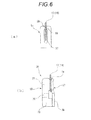
Fig. 6 , (a) is a longitudinal sectional view which shows that the fuse contacts the mating terminals to which the fuse is mounted as shown inFig. 2 , and (b) is a longitudinal sectional view which shows that the fuse contacts the double mating terminals to which the fuse is mounted as shown inFig.5 . -
Fig. 7 is a planar view of the power supply box on which the fuse is mounted shown inFig. 1 . -
Fig. 8 is a perspective view of main parts of a chain fuse in which the fuse shown inFig. 1 is used. -
Fig. 9 is an exploded perspective view of a traditional cartridge fusible link. -
Fig. 10 is a planar view of a traditional power supply box which carries blade fuses and cartridge fusible links. - A fuse according to one embodiment of the present invention is described in detail as follows with reference to the attached drawings.
- A
fusible link 11 according to a first embodiment of the present invention, as shown inFigs. 1 to 3 (b) , is a fuse which mainly includes afuse element 13 and aninsulative housing 15. - The
fuse element 13 is provided with a generally belt-shapedfusible conductor part 25 which has amelting part 31, on which a low meltingpoint metal chip 23 is mounted, between parallelinner side edges 21 of a firstplanar terminal part 17 and a secondplanar terminal part 19. In thefuse element 13, the firstplanar terminal part 17 and the secondplanar terminal part 19 which are connected to an electric circuit and the generally belt-shapedfusible conductor part 25 which is electrically connected to the firstplanar terminal part 17 and the secondplanar terminal part 19 are integrally formed by press-molding a metal plate such as a copper (Cu) plate or an aluminum (Al) plate which serves as a base material. - The width of the
fusible conductor part 25 may be narrowed to be more easily melted based on predetermined melting performance. That is, the rated current capacity of thefusible link 11 can be changed or variable by changing at least one of the conductivity of thefuse element 13 and a width W of thefusible conductor part 25 which has themelting part 31. Thereby, it is possible to change to an appropriate fuse performance (rated current capacity) to match different specifications for thefusible link 11 while the same external shape is maintained. That is, it is not necessary to upsize thefusible link 11 to match the rated current capacity. - As shown in
Figs. 1 ,3(a) and 3(b) , thefusible conductor part 25 is formed with themelting part 31 which includes a pair ofcrimping pieces 29. Thecrimping pieces 29 extend in the widthwise direction of thefusible conductor part 25, respectively, and by being crimped by thecrimping pieces 29, the low meltingpoint metal chip 23 whose melting point is lower than thefuse element 13 is crimped and fixed to the meltingpart 31. The low meltingpoint metal chip 23 is made of low melting point metal such as tin (Sn) or tin alloy whose melting point is lower than copper which is the base material of the firstplanar terminal part 17, the secondplanar terminal part 19 and thefusible conductor part 25. - Thus, the
fuse element 13 according to the present embodiment is formed into a so-called time delay fuse which, when an overcurrent passes through thefusible conductor part 25, ensures a time delay before thefusible conductor part 25 melts because the heat generated in themelting part 31 is transmitted to and absorbed by the low meltingpoint metal chip 23. - That is, for a load circuit such as an electric motor, when the electric motor is started, a momentary overcurrent whose value is several times of a steady load current value flows, and for a power window motor, at the time of motor locking when the window glass is shut or opened, a motor locking current whose value is several times of a steady load current value flows. Then, an electric current which exceeds the steady current value frequently flows even if there is no abnormality such as a circuit short. Thus, when the above-described
fuse element 13 is used, the momentary overcurrent or the motor locking current whose value exceeds a steady current value will not cause the fuse to melt, but when a slight short happens, the fuse will melt quickly so that an overcurrent can be surely cut off. - The
insulative housing 15 according to the present embodiment is integrally molded by synthetic resin material. A meltingpart accommodating space 35, as shown inFigs. 3(a) and 3(b) , is formed in theinsulative housing 15 to accommodate themelting part 31. Theinsulative housing 15 is mounted to the front surface side of thefuse element 13 to cover the inner side edges 21 of the first planarterminal part 17 and the second planarterminal part 19 and themelting part 31. - Four
welding bosses 37 are protruded from the mounting surface of theinsulative housing 15. Thewelding bosses 37 are inserted into engagingrecesses 41 which are formed respectively at the upper andlower edges 39 of the first planarterminal part 17 and the second planarterminal part 19, and insertion distal ends 43 of thewelding bosses 37 are welded at the insertion back surface sides of the engaging recesses 41. Thereby, the operation of installing theinsulative housing 15 to thefuse element 13 becomes easy and the productivity is improved without increasing the number of components. Since theinsulative housing 15 surely covers themelting part 31 of thefuse element 13, the melting fragments are prevented from flying to damage otherfusible links 11 or the like. - A top
surface cover part 45 which is approximately T-shaped when viewed from top is formed at the top surface of theinsulative housing 15. The topsurface cover part 45 covers a part (near the engaging recesses 41) at the upper parts of the first planarterminal part 17 and the second planarterminal part 19. The topsurface cover part 45 prevents the melting fragments from flying upwards, and, when thefusible link 11 which is mounted in afusible link cavity 55 of apower supply box 47 to be described below is pulled out, twoends 45a of the topsurface cover part 45 become engaging parts which are engaged with a pulling-out tool. - As shown in
Fig. 2 , thefusible link 11 according to the first embodiment is mounted tomating terminals 51 which are provided with, for example, U-shaped terminal insertion cuts 57. - The
mating terminal 51 has such a shape that the U-shaped terminal insertion cut 57 is formed, and contactingsalients 59 which make the opening narrower are formed at the entrance of the terminal insertion cut 57. - When the first planar
terminal part 17 and the second planarterminal part 19 are respectively inserted into the terminal insertion cuts 57 of a pair ofmating terminals 51, the front surfaces and the back surfaces contact the contactingsalients 59. Thereby, the pair ofmating terminals 51 is connected electrically. - As shown in
Fig. 4 , thefusible link 11 can be mounted todouble mating terminals 61. - The
double mating terminal 61 is a mating terminal which includes a pair of parallel terminal insertion cuts 57 and is formed by punching a metal plate into two parts of the same shape as theabove mating terminal 51 which are joined together by a joiningpart 63 and bending the metal plate at the joiningpart 63 by 180 degrees so that the two parts are overlapped. - In this way, since the first planar
terminal part 17 and the second planarterminal part 19 of thefusible link 11 are respectively connected to the pair ofdouble mating terminals 61, four places can contact the contactingsalients 59 at one side, and stable electrical connection can be realized and high connecting reliability can be achieved. - Furthermore, as shown in
Fig. 5 , thefusible link 11 also can be mounted tobended mating terminals 65. - The
bended mating terminal 65 includes aterminal piece 67, which is parallel to the first planarterminal part 17 and the second planarterminal part 19, at one side, and aperpendicular terminal piece 69, which is formed by being bended to be perpendicular to theterminal piece 67, at the other side. - That is, the
perpendicular terminal piece 69 includes aterminal base part 73 which is bended by 90 degrees relative to aterminal base part 76 of theterminal piece 67, aninclined part 75 which is formed above theterminal base part 73, and a contactingpiece 77 which is arranged at the middle of theterminal piece 67 in the widthwise direction. A receivingsurface 71 is formed at the top surface of theterminal piece 67 to guide the insertion of the first planarterminal part 17 and the second planarterminal part 19. - In this way, since the first planar
terminal part 17 and the second planarterminal part 19 of thefusible link 11 are connected by a pair of thebended mating terminals 65, respectively, compared to the case where the first planarterminal part 17 and the second planarterminal part 19 are connected by themating terminals 51 as shown inFig. 6(a) , when the first planarterminal part 17 and the second planarterminal part 19 are connected by thebended mating terminals 65, as shown inFig. 6(b) , the areas in which the first planarterminal part 17 or the second planarterminal part 19 contacts thebended mating terminals 65 can be significantly increased, and the electrical connection of thefusible link 11 of a large rated current capacity type is realized. - Then, the operations of the
fusible link 11 which has the above-described structure are described. - As described above, in the
fusible link 11 according to the present embodiment, thefuse element 13, which is provided with themelting part 31 on which the low meltingpoint metal chip 23 is mounted between the first planarterminal part 17 and the second planarterminal part 19 which are arranged in the same plane, is formed to be generally planar-shaped. The front surface side of thefuse element 13 is covered with theinsulative housing 15 in which the meltingpart accommodating space 35 is formed to accommodate themelting part 31. - That is, the
fusible link 11 is flat as a whole while the site where theinsulative housing 15 covers themelting part 31 is thickened partially. Thus, a plurality offusible links 11 can be overlapped in parallel in the plate thickness direction of thefuse element 13, or a plurality offusible links 11 can be arranged side by side to fuse circuits in the same plane. - Therefore, since the
fusible link 11 of the present embodiment is provided with two components, which are thefuse element 13 and theinsulative housing 15, and since the freedom in layout increases due to the flat shape, the component number may be decreased, the space of the power supply box 47 (refer toFig. 7 ) can be saved, and thefusible link 11 may be commonly used in a chain fusible link 49 (refer toFig. 8 ). - As shown in
Fig. 7 , thepower supply box 47 which carries thefusible links 11 as described above, includes a blade fuse area 52 (an area enclosed by one-dot-chain lines inFig. 7 ) which is divided vertically and horizontally intoblade fuse cavities 519 to accommodate a number of blade fuses 517, respectively, and a fusible link area 53 (an area enclosed by dashed lines inFig. 7 ) which is divided vertically and horizontally intofusible link cavities 55 of the same shape to accommodate a plurality of thefusible links 11. Thefusible link cavities 55 are provided with a pair ofbended mating terminals 65, respectively. - The
power supply box 47 according to the present embodiment includes fuse circuits, the number of which is the same as that of the traditionalpower supply box 515 shown inFig. 10 . - The
blade fuse area 52 of thepower supply box 47 shown inFig. 7 has approximately the same size as theblade fuse area 520 of the traditionalpower supply box 515 shown inFig. 10 , but thefusible link area 53 to accommodate thefusible links 11 is significantly downsized compared to thefusible link area 530 of thepower supply box 515 as shown inFig. 10 . To make it easy to compare the sizes, thefusible link area 530 of thepower supply box 515 is illustrated by two-dots-chain lines inFig. 7 . - That is, since a plurality of flat
fusible links 11, which, even if the rated current capacity differs from each other, have the same shape, are overlapped in parallel in the plate thickness direction of thefuse element 13 as shown inFig. 7 , thefusible link cavities 55 of the same size can be arranged to be aligned vertically and horizontally. Thus, when compared to thefusible link area 530, which is divided into cartridge fusible linkcavities 521 with different sizes, thefusible link area 53 of thepower supply box 47 according to the present embodiment can be compacted and the space of thepower supply box 515 can be saved. - Then, a
fusible link 11 according to a second embodiment of the present invention is described. - A chain fusible link 49 shown in
Fig. 8 is formed as a chain fuse between the battery of a vehicle and the electronic components mounted in the vehicle by using thefusible link 11 described above, and the problem that the fuse circuits become complicated as the electronic components increases can be easily coped with. - The chain fusible link 49 according to the present embodiment includes a
block base part 87, a connectingplate part 79, thefusible link 11 andterminal parts 95. - The
block base part 87 is formed of insulative resin material, and is so set that most of the connectingplate part 79 andterminal parts 95 are embedded inside theblock base part 87 by insert-molding. Fuseaccommodating parts 87A to 87D, which are recessed into concave shapes, are formed in theblock base part 87 to accommodate thefusible link 11. Furthermore, threerecesses 91 are formed at the lower part of theblock base part 87 in which LA terminals (not shown in the figure) are screw-fixed. - The connecting
plate part 79 is formed of conductive material such as metal plate and is integrally embedded in theblock base part 87 with two ends exposed from theblock base part 87 to form bus bars. The connectingplate part 79 is provided withholes 89 at the two ends (terminals 83, 85) so that LA terminals which are attached to electric wires can be attached by being screw-fixed. - That is, the connecting
plate part 79 according to the present embodiment is divided into two parts which are electrically connected with afusible link 11a. The connecting plate part at one side (refer to a first connectingplate part 79A), as described previously, is integrally embedded in theblock base part 87 with the tongue-shaped metal part, which becomes the terminal 83 for connecting to the LA terminal, exposed at the end. The connecting plate part at the other side (refer to a second connectingplate part 79B), is also integrally embedded in theblock base part 87 with the tongue-shaped metal part, which becomes the terminal 85 for connecting to the LA terminal, exposed at the end. - For the
fusible link 11 according to the present embodiment, four kinds offusible links 11a to 11d which have appropriate fuse performances (rated current capacities) are mounted in thefuse accommodating parts 87A to 87D formed at theblock base part 87 respectively so that each of thefuse accommodating parts 87A to 87D has appropriate maximum allowable currents. - The
terminal parts 95 of the present embodiment include threeterminals recesses 91 formed at the lower part of theblock base part 87 to connect the LA terminals, and most parts of theterminal parts 95 are integrally embedded in theblock base part 87.Posts 97 are protruded from theterminals - The fuse
accommodating parts 87A to 87D of theblock base part 87 are electrically connected to thefusible links 11a to 11d, respectively. In this case, edges at one side of the first connectingplate part 79A and the second connectingplate part 79B, and the ends of theterminals fuse accommodating parts 87A to 87D, the first planarterminal parts 17 of thefusible links 11a to 11d are connected to the edges at one side of the connectingplate part 79, and the second planarterminal parts 19 are connected to the ends of theterminals fusible links 11a to 11d. - According to the above-described chain
fusible link 49, since the connectingplate part 79 and theterminal part 95 are connected by thefusible conductor part 25 of thefusible link 11, the chain fusible link, which integrally includes a plurality of fuse circuits between a battery terminal of a battery and output side electric circuits, can be easily constructed. That is, since thefusible link 11 according to the present embodiment is flat as a whole, a plurality offusible links 11 can be arranged side by side in fuse circuits which are formed by the connectingplate part 79 and theterminal parts 95 in the same plane. - According to the
fusible link 11 of the present embodiment, thefusible link 11 used in thepower supply box 47 can be commonly used in the chainfusible link 49, and because the equipment amortization expense of thefusible link 11 is reduced, the cost may be reduced. - The constructions of the first and the second planar terminal parts, the melting part, the fuse element, the insulative housing, the welding bosses, the engaging recesses, the connecting plate and the terminal part according to the present invention are not limited to the constructions of the above embodiments, it is apparent that various embodiments may be adopted based on the purpose of the present invention.
- For example, in the above-described embodiment, the
cylindrical welding bosses 37 and the generally semicircular engagingrecesses 41 are used to mount theinsulative housing 15 to thefuse element 13, but the shapes of these welding bosses and engaging recesses are not limited, and various kinds of shapes such as oval or polygon shapes may be adopted. - The present application is based on the Japanese patent application No.
2011-095957 filed on April 22, 2011 - The fuse of the present invention is provided with two components, which are the fuse element and the insulative housing, and since the freedom in layout increases due to the flat shape, the component number may be decreased, the space of the power supply box can be saved, and the fuse may be commonly used in a chain fuse.
-
- 11:
- fusible link (fuse)
- 13:
- fuse element
- 15:
- insulative housing
- 17:
- first planar terminal part
- 19:
- second planar terminal part
- 21:
- inner side edge
- 23:
- low melting point metal chip
- 25:
- fusible conductor part
- 31:
- melting part
- 35:
- melting part accommodating space
- 37:
- welding boss
- 39:
- upper and lower edges
- 41:
- engaging recess
Claims (5)
- A fuse comprising:a fuse element which includes a first planar terminal part, a second planar terminal part, and a melting part, wherein the melting part is provided between parallel inner side edges of the first planar terminal part and the second planar terminal part and has a low melting point metal chip; andan insulative housing, having a melting part accommodating space to accommodate the melting part therein, which is mounted to a front surface side of the fuse element to cover the inner side edges of the first planar terminal part and the second planar terminal part and the melting part.
- The fuse according to claim 1, wherein
welding bosses which are protruded from a mounting surface of the insulative housing are welded in engaging recesses which are formed at upper and lower edges of the first planar terminal part and the second planar terminal part. - The fuse according to claim 1 or 2, wherein
a rated current capacity of the fuse is variable by changing at least one of a conductivity of the fuse element and a width of a fusible conductor part which has the melting part. - The fuse according to claim 1 or 2, wherein
the first planar terminal part is electrically connected by being connected to a connecting plate which is electrically connected to a battery terminal, and
the second planar terminal part is electrically connected by being connected to a terminal part which is electrically connected to an output side electric circuit. - The fuse according to claim 3, wherein
the first planar terminal part is electrically connected by being connected to a connecting plate which is electrically connected to a battery terminal, and
the second planar terminal part is electrically connected by being connected to a terminal part which is electrically connected to an output side electric circuit.
Applications Claiming Priority (2)
| Application Number | Priority Date | Filing Date | Title |
|---|---|---|---|
| JP2011095957A JP5771057B2 (en) | 2011-04-22 | 2011-04-22 | fuse |
| PCT/JP2012/060636 WO2012144569A1 (en) | 2011-04-22 | 2012-04-19 | Fuse |
Publications (2)
| Publication Number | Publication Date |
|---|---|
| EP2701177A1 true EP2701177A1 (en) | 2014-02-26 |
| EP2701177A4 EP2701177A4 (en) | 2014-10-29 |
Family
ID=47041674
Family Applications (1)
| Application Number | Title | Priority Date | Filing Date |
|---|---|---|---|
| EP12774483.7A Withdrawn EP2701177A4 (en) | 2011-04-22 | 2012-04-19 | FUSE |
Country Status (5)
| Country | Link |
|---|---|
| US (1) | US9685294B2 (en) |
| EP (1) | EP2701177A4 (en) |
| JP (1) | JP5771057B2 (en) |
| CN (1) | CN103493170B (en) |
| WO (1) | WO2012144569A1 (en) |
Families Citing this family (12)
| Publication number | Priority date | Publication date | Assignee | Title |
|---|---|---|---|---|
| JP6063266B2 (en) * | 2013-01-16 | 2017-01-18 | 矢崎総業株式会社 | Fuse unit |
| JP5982294B2 (en) * | 2013-02-05 | 2016-08-31 | 太平洋精工株式会社 | Blade fuse |
| JP2014154284A (en) | 2013-02-06 | 2014-08-25 | Yazaki Corp | Fuse, and manufacturing method of fuse |
| KR102002448B1 (en) * | 2015-09-02 | 2019-07-23 | 주식회사 엘지화학 | Battery pack |
| US20180218868A1 (en) * | 2017-01-31 | 2018-08-02 | Continental Automotive Systems, Inc. | In-line blade fuse system |
| JP7002955B2 (en) * | 2017-02-28 | 2022-01-20 | デクセリアルズ株式会社 | Fuse element |
| US9997851B1 (en) | 2017-04-21 | 2018-06-12 | Hewlett Packard Enterprise Development Lp | Power connectors with fusible regions |
| US11101093B2 (en) * | 2019-01-21 | 2021-08-24 | Littelfuse, Inc. | Fuses and methods of forming fuses |
| CN110867357B (en) * | 2019-12-03 | 2025-04-11 | Aem科技(苏州)股份有限公司 | A surface mount fuse |
| JP7041185B2 (en) * | 2020-04-07 | 2022-03-23 | 矢崎総業株式会社 | Fuse unit |
| CN114005714A (en) * | 2021-10-15 | 2022-02-01 | 杭州精晟新能源科技有限公司 | Fuse protector |
| JP7713160B2 (en) * | 2021-12-24 | 2025-07-25 | 株式会社オートネットワーク技術研究所 | Fuse Unit |
Family Cites Families (42)
| Publication number | Priority date | Publication date | Assignee | Title |
|---|---|---|---|---|
| CA1169898A (en) * | 1980-04-28 | 1984-06-26 | Pacific Engineering Co., Ltd. | Fuse |
| JPS5921500Y2 (en) * | 1982-03-19 | 1984-06-25 | 三王株式会社 | Ultra-compact fuse with lead |
| US4608548A (en) * | 1985-01-04 | 1986-08-26 | Littelfuse, Inc. | Miniature fuse |
| US4635023A (en) * | 1985-05-22 | 1987-01-06 | Littelfuse, Inc. | Fuse assembly having a non-sagging suspended fuse link |
| US4894633A (en) * | 1988-12-12 | 1990-01-16 | American Telephone And Telegraph Company | Fuse Apparatus |
| JPH0720828Y2 (en) * | 1989-06-14 | 1995-05-15 | エス・オー・シー株式会社 | Ultra-small current fuse |
| JPH052360U (en) | 1991-06-25 | 1993-01-14 | 矢崎総業株式会社 | Pressure contact fuse |
| US5229739A (en) | 1992-02-21 | 1993-07-20 | Littelfuse, Inc. | Automotive high current fuse |
| JP2552868Y2 (en) * | 1992-12-01 | 1997-10-29 | 矢崎総業株式会社 | Slow fuse |
| JPH06342623A (en) * | 1993-06-01 | 1994-12-13 | S O C Kk | Chip fuse |
| JP2557019B2 (en) * | 1993-10-01 | 1996-11-27 | エス・オー・シー株式会社 | Ultra-small chip fuse and manufacturing method thereof |
| JP2747877B2 (en) * | 1993-10-28 | 1998-05-06 | 矢崎総業株式会社 | Slow fuse and manufacturing method thereof |
| US5668521A (en) * | 1995-03-22 | 1997-09-16 | Littelfuse, Inc. | Three piece female blade fuse assembly having fuse link terminal with a clip receiving portion |
| IT1282131B1 (en) * | 1996-04-24 | 1998-03-12 | Codognese Meccanotec | AUTOMOTIVE TYPE HIGH CURRENT FUSE. |
| JPH10199396A (en) | 1997-01-13 | 1998-07-31 | Taiheiyo Seiko Kk | Mutipole type fuse element and multipole type fuse using such element |
| JPH10283906A (en) * | 1997-04-08 | 1998-10-23 | Taiheiyo Seiko Kk | Circuit connector serving also as fuse |
| JP3719475B2 (en) * | 1998-01-20 | 2005-11-24 | 矢崎総業株式会社 | High current fuse |
| JP2000164111A (en) * | 1998-03-16 | 2000-06-16 | Yazaki Corp | High current fuse for automobile |
| JP3194429B2 (en) * | 1998-06-02 | 2001-07-30 | オムロン株式会社 | Overcurrent cutoff structure |
| JP2000113803A (en) | 1998-10-01 | 2000-04-21 | Yazaki Corp | High current fuse for automobile |
| JP4096431B2 (en) * | 1998-12-11 | 2008-06-04 | 太平洋精工株式会社 | Multiple fuse element and multiple fuse using the multiple fuse element |
| JP2000195408A (en) * | 1998-12-28 | 2000-07-14 | Sumitomo Wiring Syst Ltd | Electrical connection box |
| US6642834B1 (en) * | 1999-03-04 | 2003-11-04 | Littelfuse, Inc. | High voltage automotive use |
| US6577222B1 (en) * | 1999-04-02 | 2003-06-10 | Littelfuse, Inc. | Fuse having improved fuse housing |
| JP2001110297A (en) * | 1999-10-05 | 2001-04-20 | Yazaki Corp | High current fuse |
| EP1134769A1 (en) * | 2000-03-08 | 2001-09-19 | Cooper Bussmann UK Limited | A method of applying M-effect material |
| US6486766B1 (en) * | 2000-03-14 | 2002-11-26 | Littlefuse, Inc. | Housing for double-ended fuse |
| JP3630364B2 (en) * | 2000-03-27 | 2005-03-16 | 矢崎総業株式会社 | Fuse structure |
| JP3722421B2 (en) * | 2001-04-06 | 2005-11-30 | 矢崎総業株式会社 | Fuse box |
| US7612646B2 (en) * | 2003-04-04 | 2009-11-03 | Yazaki Corporation | Fuse cavity structure and electric connection box |
| EP1797576A4 (en) * | 2004-09-15 | 2008-12-10 | Littelfuse Inc | High voltage/high current fuse |
| JP4917927B2 (en) * | 2007-03-15 | 2012-04-18 | 太平洋精工株式会社 | Multiple fuse unit for vehicles |
| JP5081581B2 (en) | 2007-10-30 | 2012-11-28 | 矢崎総業株式会社 | Fusible link unit |
| US20090189730A1 (en) * | 2008-01-30 | 2009-07-30 | Littelfuse, Inc. | Low temperature fuse |
| JP5207533B2 (en) * | 2008-09-05 | 2013-06-12 | 矢崎総業株式会社 | Composite fusible link, fuse box and manufacturing method thereof |
| JP2010108787A (en) | 2008-10-30 | 2010-05-13 | Yazaki Corp | Adapter for blade fuse, spare cartridge fuse using it, and fuse box |
| JP2010161017A (en) * | 2009-01-09 | 2010-07-22 | Yazaki Corp | Cylindrical protection cap |
| US8937524B2 (en) * | 2009-03-25 | 2015-01-20 | Littelfuse, Inc. | Solderless surface mount fuse |
| JP2010287443A (en) * | 2009-06-12 | 2010-12-24 | Yazaki Corp | Fuse |
| US8203420B2 (en) * | 2009-06-26 | 2012-06-19 | Cooper Technologies Company | Subminiature fuse with surface mount end caps and improved connectivity |
| CN201780951U (en) * | 2010-04-29 | 2011-03-30 | 比亚迪股份有限公司 | A new type of fuse |
| US8629749B2 (en) * | 2010-11-30 | 2014-01-14 | Hung-Chih Chiu | Fuse assembly |
-
2011
- 2011-04-22 JP JP2011095957A patent/JP5771057B2/en active Active
-
2012
- 2012-04-19 CN CN201280019530.XA patent/CN103493170B/en not_active Expired - Fee Related
- 2012-04-19 WO PCT/JP2012/060636 patent/WO2012144569A1/en not_active Ceased
- 2012-04-19 EP EP12774483.7A patent/EP2701177A4/en not_active Withdrawn
-
2013
- 2013-10-15 US US14/053,814 patent/US9685294B2/en not_active Expired - Fee Related
Also Published As
| Publication number | Publication date |
|---|---|
| US20140035717A1 (en) | 2014-02-06 |
| US9685294B2 (en) | 2017-06-20 |
| JP2012227091A (en) | 2012-11-15 |
| JP5771057B2 (en) | 2015-08-26 |
| EP2701177A4 (en) | 2014-10-29 |
| WO2012144569A1 (en) | 2012-10-26 |
| CN103493170A (en) | 2014-01-01 |
| CN103493170B (en) | 2015-09-09 |
Similar Documents
| Publication | Publication Date | Title |
|---|---|---|
| US9685294B2 (en) | Fuse | |
| JP4917927B2 (en) | Multiple fuse unit for vehicles | |
| US6830482B2 (en) | Fusible link and method of producing said fusible link | |
| EP0939453B1 (en) | An electrical connection box | |
| EP1336978B1 (en) | Blade fuse | |
| US8721367B2 (en) | Fuse unit | |
| US9607798B2 (en) | Fuse unit | |
| CN108231616B (en) | Voltage detection structure and voltage detection module | |
| KR101370196B1 (en) | Fusible link unit | |
| JP2018097987A (en) | Conductor connection structure and conductive module | |
| JP2003037920A (en) | Electrical connection box | |
| KR20190039378A (en) | Vehicle electrical center and method of manufacturing same | |
| JP7412035B1 (en) | Fuse and method for manufacturing the fuse | |
| JP7704438B2 (en) | Manufacturing method for blade type fuse | |
| WO2023153347A1 (en) | Wiring module | |
| TW202133207A (en) | Current-limiting fuse | |
| JP4096800B2 (en) | Automotive relay box | |
| JP3994908B2 (en) | Electrical junction box for automobiles | |
| KR102925579B1 (en) | fuse | |
| US20250273419A1 (en) | Fuse unit | |
| JP2008021488A (en) | fuse | |
| JP5603699B2 (en) | Fuse unit | |
| KR20250120989A (en) | fuse | |
| JPH09260110A (en) | Conductor connection part by PTC element |
Legal Events
| Date | Code | Title | Description |
|---|---|---|---|
| PUAI | Public reference made under article 153(3) epc to a published international application that has entered the european phase |
Free format text: ORIGINAL CODE: 0009012 |
|
| 17P | Request for examination filed |
Effective date: 20131018 |
|
| AK | Designated contracting states |
Kind code of ref document: A1 Designated state(s): AL AT BE BG CH CY CZ DE DK EE ES FI FR GB GR HR HU IE IS IT LI LT LU LV MC MK MT NL NO PL PT RO RS SE SI SK SM TR |
|
| DAX | Request for extension of the european patent (deleted) | ||
| A4 | Supplementary search report drawn up and despatched |
Effective date: 20140925 |
|
| RIC1 | Information provided on ipc code assigned before grant |
Ipc: H01H 85/20 20060101ALI20140919BHEP Ipc: H01H 85/175 20060101AFI20140919BHEP Ipc: H01H 85/02 20060101ALI20140919BHEP Ipc: H01H 85/147 20060101ALI20140919BHEP Ipc: H01H 85/165 20060101ALI20140919BHEP Ipc: H01H 85/153 20060101ALI20140919BHEP Ipc: H01H 85/11 20060101ALI20140919BHEP Ipc: H01H 85/045 20060101ALI20140919BHEP |
|
| 17Q | First examination report despatched |
Effective date: 20161129 |
|
| STAA | Information on the status of an ep patent application or granted ep patent |
Free format text: STATUS: THE APPLICATION IS DEEMED TO BE WITHDRAWN |
|
| 18D | Application deemed to be withdrawn |
Effective date: 20190409 |