JP2018097987A - Connection structure of conductor and conductive module - Google Patents
Connection structure of conductor and conductive module Download PDFInfo
- Publication number
- JP2018097987A JP2018097987A JP2016239796A JP2016239796A JP2018097987A JP 2018097987 A JP2018097987 A JP 2018097987A JP 2016239796 A JP2016239796 A JP 2016239796A JP 2016239796 A JP2016239796 A JP 2016239796A JP 2018097987 A JP2018097987 A JP 2018097987A
- Authority
- JP
- Japan
- Prior art keywords
- conductor
- connection
- fusible body
- battery
- linear
- Prior art date
- Legal status (The legal status is an assumption and is not a legal conclusion. Google has not performed a legal analysis and makes no representation as to the accuracy of the status listed.)
- Granted
Links
Images


Classifications
-
- H—ELECTRICITY
- H01—ELECTRIC ELEMENTS
- H01M—PROCESSES OR MEANS, e.g. BATTERIES, FOR THE DIRECT CONVERSION OF CHEMICAL ENERGY INTO ELECTRICAL ENERGY
- H01M10/00—Secondary cells; Manufacture thereof
- H01M10/05—Accumulators with non-aqueous electrolyte
- H01M10/052—Li-accumulators
- H01M10/0525—Rocking-chair batteries, i.e. batteries with lithium insertion or intercalation in both electrodes; Lithium-ion batteries
-
- H—ELECTRICITY
- H01—ELECTRIC ELEMENTS
- H01M—PROCESSES OR MEANS, e.g. BATTERIES, FOR THE DIRECT CONVERSION OF CHEMICAL ENERGY INTO ELECTRICAL ENERGY
- H01M10/00—Secondary cells; Manufacture thereof
- H01M10/42—Methods or arrangements for servicing or maintenance of secondary cells or secondary half-cells
- H01M10/4207—Methods or arrangements for servicing or maintenance of secondary cells or secondary half-cells for several batteries or cells simultaneously or sequentially
-
- H—ELECTRICITY
- H01—ELECTRIC ELEMENTS
- H01M—PROCESSES OR MEANS, e.g. BATTERIES, FOR THE DIRECT CONVERSION OF CHEMICAL ENERGY INTO ELECTRICAL ENERGY
- H01M10/00—Secondary cells; Manufacture thereof
- H01M10/42—Methods or arrangements for servicing or maintenance of secondary cells or secondary half-cells
- H01M10/48—Accumulators combined with arrangements for measuring, testing or indicating the condition of cells, e.g. the level or density of the electrolyte
- H01M10/482—Accumulators combined with arrangements for measuring, testing or indicating the condition of cells, e.g. the level or density of the electrolyte for several batteries or cells simultaneously or sequentially
-
- H—ELECTRICITY
- H01—ELECTRIC ELEMENTS
- H01M—PROCESSES OR MEANS, e.g. BATTERIES, FOR THE DIRECT CONVERSION OF CHEMICAL ENERGY INTO ELECTRICAL ENERGY
- H01M50/00—Constructional details or processes of manufacture of the non-active parts of electrochemical cells other than fuel cells, e.g. hybrid cells
- H01M50/50—Current conducting connections for cells or batteries
- H01M50/502—Interconnectors for connecting terminals of adjacent batteries; Interconnectors for connecting cells outside a battery casing
- H01M50/521—Interconnectors for connecting terminals of adjacent batteries; Interconnectors for connecting cells outside a battery casing characterised by the material
- H01M50/524—Organic material
-
- H—ELECTRICITY
- H01—ELECTRIC ELEMENTS
- H01M—PROCESSES OR MEANS, e.g. BATTERIES, FOR THE DIRECT CONVERSION OF CHEMICAL ENERGY INTO ELECTRICAL ENERGY
- H01M50/00—Constructional details or processes of manufacture of the non-active parts of electrochemical cells other than fuel cells, e.g. hybrid cells
- H01M50/50—Current conducting connections for cells or batteries
- H01M50/572—Means for preventing undesired use or discharge
- H01M50/574—Devices or arrangements for the interruption of current
- H01M50/581—Devices or arrangements for the interruption of current in response to temperature
-
- H—ELECTRICITY
- H01—ELECTRIC ELEMENTS
- H01R—ELECTRICALLY-CONDUCTIVE CONNECTIONS; STRUCTURAL ASSOCIATIONS OF A PLURALITY OF MUTUALLY-INSULATED ELECTRICAL CONNECTING ELEMENTS; COUPLING DEVICES; CURRENT COLLECTORS
- H01R11/00—Individual connecting elements providing two or more spaced connecting locations for conductive members which are, or may be, thereby interconnected, e.g. end pieces for wires or cables supported by the wire or cable and having means for facilitating electrical connection to some other wire, terminal, or conductive member, blocks of binding posts
- H01R11/03—Individual connecting elements providing two or more spaced connecting locations for conductive members which are, or may be, thereby interconnected, e.g. end pieces for wires or cables supported by the wire or cable and having means for facilitating electrical connection to some other wire, terminal, or conductive member, blocks of binding posts characterised by the relationship between the connecting locations
- H01R11/05—Individual connecting elements providing two or more spaced connecting locations for conductive members which are, or may be, thereby interconnected, e.g. end pieces for wires or cables supported by the wire or cable and having means for facilitating electrical connection to some other wire, terminal, or conductive member, blocks of binding posts characterised by the relationship between the connecting locations the connecting locations having different types of direct connections
-
- H—ELECTRICITY
- H01—ELECTRIC ELEMENTS
- H01M—PROCESSES OR MEANS, e.g. BATTERIES, FOR THE DIRECT CONVERSION OF CHEMICAL ENERGY INTO ELECTRICAL ENERGY
- H01M2200/00—Safety devices for primary or secondary batteries
- H01M2200/10—Temperature sensitive devices
- H01M2200/103—Fuse
-
- H—ELECTRICITY
- H01—ELECTRIC ELEMENTS
- H01M—PROCESSES OR MEANS, e.g. BATTERIES, FOR THE DIRECT CONVERSION OF CHEMICAL ENERGY INTO ELECTRICAL ENERGY
- H01M2220/00—Batteries for particular applications
- H01M2220/20—Batteries in motive systems, e.g. vehicle, ship, plane
-
- H—ELECTRICITY
- H01—ELECTRIC ELEMENTS
- H01M—PROCESSES OR MEANS, e.g. BATTERIES, FOR THE DIRECT CONVERSION OF CHEMICAL ENERGY INTO ELECTRICAL ENERGY
- H01M50/00—Constructional details or processes of manufacture of the non-active parts of electrochemical cells other than fuel cells, e.g. hybrid cells
- H01M50/20—Mountings; Secondary casings or frames; Racks, modules or packs; Suspension devices; Shock absorbers; Transport or carrying devices; Holders
- H01M50/249—Mountings; Secondary casings or frames; Racks, modules or packs; Suspension devices; Shock absorbers; Transport or carrying devices; Holders specially adapted for aircraft or vehicles, e.g. cars or trains
-
- H—ELECTRICITY
- H01—ELECTRIC ELEMENTS
- H01M—PROCESSES OR MEANS, e.g. BATTERIES, FOR THE DIRECT CONVERSION OF CHEMICAL ENERGY INTO ELECTRICAL ENERGY
- H01M50/00—Constructional details or processes of manufacture of the non-active parts of electrochemical cells other than fuel cells, e.g. hybrid cells
- H01M50/50—Current conducting connections for cells or batteries
- H01M50/502—Interconnectors for connecting terminals of adjacent batteries; Interconnectors for connecting cells outside a battery casing
- H01M50/503—Interconnectors for connecting terminals of adjacent batteries; Interconnectors for connecting cells outside a battery casing characterised by the shape of the interconnectors
-
- H—ELECTRICITY
- H01—ELECTRIC ELEMENTS
- H01M—PROCESSES OR MEANS, e.g. BATTERIES, FOR THE DIRECT CONVERSION OF CHEMICAL ENERGY INTO ELECTRICAL ENERGY
- H01M50/00—Constructional details or processes of manufacture of the non-active parts of electrochemical cells other than fuel cells, e.g. hybrid cells
- H01M50/50—Current conducting connections for cells or batteries
- H01M50/502—Interconnectors for connecting terminals of adjacent batteries; Interconnectors for connecting cells outside a battery casing
- H01M50/514—Methods for interconnecting adjacent batteries or cells
- H01M50/516—Methods for interconnecting adjacent batteries or cells by welding, soldering or brazing
-
- H—ELECTRICITY
- H01—ELECTRIC ELEMENTS
- H01M—PROCESSES OR MEANS, e.g. BATTERIES, FOR THE DIRECT CONVERSION OF CHEMICAL ENERGY INTO ELECTRICAL ENERGY
- H01M50/00—Constructional details or processes of manufacture of the non-active parts of electrochemical cells other than fuel cells, e.g. hybrid cells
- H01M50/50—Current conducting connections for cells or batteries
- H01M50/543—Terminals
- H01M50/547—Terminals characterised by the disposition of the terminals on the cells
- H01M50/55—Terminals characterised by the disposition of the terminals on the cells on the same side of the cell
-
- H—ELECTRICITY
- H01—ELECTRIC ELEMENTS
- H01R—ELECTRICALLY-CONDUCTIVE CONNECTIONS; STRUCTURAL ASSOCIATIONS OF A PLURALITY OF MUTUALLY-INSULATED ELECTRICAL CONNECTING ELEMENTS; COUPLING DEVICES; CURRENT COLLECTORS
- H01R2201/00—Connectors or connections adapted for particular applications
- H01R2201/26—Connectors or connections adapted for particular applications for vehicles
-
- H—ELECTRICITY
- H05—ELECTRIC TECHNIQUES NOT OTHERWISE PROVIDED FOR
- H05K—PRINTED CIRCUITS; CASINGS OR CONSTRUCTIONAL DETAILS OF ELECTRIC APPARATUS; MANUFACTURE OF ASSEMBLAGES OF ELECTRICAL COMPONENTS
- H05K1/00—Printed circuits
- H05K1/02—Details
- H05K1/0213—Electrical arrangements not otherwise provided for
- H05K1/0263—High current adaptations, e.g. printed high current conductors or using auxiliary non-printed means; Fine and coarse circuit patterns on one circuit board
-
- Y—GENERAL TAGGING OF NEW TECHNOLOGICAL DEVELOPMENTS; GENERAL TAGGING OF CROSS-SECTIONAL TECHNOLOGIES SPANNING OVER SEVERAL SECTIONS OF THE IPC; TECHNICAL SUBJECTS COVERED BY FORMER USPC CROSS-REFERENCE ART COLLECTIONS [XRACs] AND DIGESTS
- Y02—TECHNOLOGIES OR APPLICATIONS FOR MITIGATION OR ADAPTATION AGAINST CLIMATE CHANGE
- Y02E—REDUCTION OF GREENHOUSE GAS [GHG] EMISSIONS, RELATED TO ENERGY GENERATION, TRANSMISSION OR DISTRIBUTION
- Y02E60/00—Enabling technologies; Technologies with a potential or indirect contribution to GHG emissions mitigation
- Y02E60/10—Energy storage using batteries
Abstract
Description
本発明は、導体の接続構造および導電モジュールに関する。 The present invention relates to a conductor connection structure and a conductive module.
従来、電気自動車(EV)やハイブリッド自動車(HEV)などの車両には、複数の電池セルからなる電池モジュールと、各電池セルの電池状態を監視するための電池監視ユニットとが搭載されている。各電池セルと電池監視ユニットとは、導電モジュールを介して互いに接続されている。導電モジュールは、電池セルの電極端子に接続されるバスバーなどの接続導体と、電池監視ユニットに接続される電線などの線状導体と、接続導体と線状導体との間に介在するヒューズと、これらを収容するケースとを備えるものがある。例えば、特許文献1には、図4に示すように、バスバー104に設けたヒューズ接続部42から中継端子7aを通り、一方の端子部81からヒューズ8を有したハウジング80を介して、他方の端子部81を通り、中継端子7b、電線9bへと接続する導電モジュールが開示されている。
Conventionally, vehicles such as an electric vehicle (EV) and a hybrid vehicle (HEV) are equipped with a battery module including a plurality of battery cells and a battery monitoring unit for monitoring the battery state of each battery cell. Each battery cell and the battery monitoring unit are connected to each other through a conductive module. The conductive module includes a connection conductor such as a bus bar connected to the electrode terminal of the battery cell, a linear conductor such as an electric wire connected to the battery monitoring unit, a fuse interposed between the connection conductor and the linear conductor, Some have a case for housing them. For example, in
上述した従来の導電モジュールでは、接続導体と線状導体との間にヒューズを介在させることで過電流に対する導電モジュールおよび電池監視ユニットの保護が可能となるが、接続導体と線状導体との間を中継する部品が増えることから小型化の点で改善の余地がある。 In the conventional conductive module described above, it is possible to protect the conductive module and the battery monitoring unit against overcurrent by interposing a fuse between the connection conductor and the linear conductor. There is room for improvement in terms of miniaturization because more parts are relayed.
本発明は、小型化を実現することができる導体の接続構造および導電モジュールを提供することを目的とする。 An object of the present invention is to provide a conductor connection structure and a conductive module that can be miniaturized.
上記目的を達成するために、本発明に係る導体の接続構造は、同一方向に配列された複数の電池セルにおける電極端子群の少なくとも1つの電極端子に直接的または間接的に接続される接続導体と、前記複数の電池セルの電池状態を監視する電池監視ユニットに接続される線状導体と、前記接続導体と前記線状導体との間に直接的または間接的に接続され、かつ、前記接続導体と前記線状導体との間を過電流が流れたときに溶断する可溶体と、前記可溶体および前記接続導体の一部を内在する絶縁性の樹脂モールド部材と、を備えることを特徴とする。 To achieve the above object, a conductor connection structure according to the present invention is a connection conductor that is directly or indirectly connected to at least one electrode terminal of an electrode terminal group in a plurality of battery cells arranged in the same direction. A linear conductor connected to a battery monitoring unit that monitors the battery state of the plurality of battery cells, and is connected directly or indirectly between the connection conductor and the linear conductor, and the connection A fusible body that melts when an overcurrent flows between a conductor and the linear conductor, and an insulating resin mold member that includes part of the fusible body and the connecting conductor. To do.
上記導体の接続構造において、前記可溶体は、金属製の中継端子を介して前記線状導体に接続され、前記樹脂モールド部材はさらに、前記中継端子の一部を内在することが好ましい。 In the conductor connection structure, it is preferable that the fusible body is connected to the linear conductor via a metal relay terminal, and the resin mold member further includes a part of the relay terminal.
上記導体の接続構造において、前記可溶体は、一対の端子と、前記一対の端子の間に設けられた溶断部とで構成され、前記一対の端子のうちの一方には前記接続導体が接続され、他方には前記線状導体または前記中継端子が接続されることが好ましい。 In the conductor connection structure, the fusible body includes a pair of terminals and a fusing part provided between the pair of terminals, and the connection conductor is connected to one of the pair of terminals. It is preferable that the linear conductor or the relay terminal is connected to the other.
上記目的を達成するために、本発明に係る導電モジュールは、同一方向に配列された複数の電池セルにおける電極端子群の少なくとも1つの電極端子に直接的または間接的に接続される接続導体と、前記複数の電池セルの電池状態を監視する電池監視ユニットに接続される線状導体と、前記接続導体と前記線状導体との間に直接的または間接的に接続され、かつ、前記接続導体と前記線状導体との間を過電流が流れたときに溶断する可溶体と、前記可溶体および前記接続導体の一部を内在する絶縁性の樹脂モールド部材と、を備える導体を少なくとも1つの前記電極端子に対応して複数備え、複数の前記接続導体は、絶縁性の収容ケースに形成され、かつ、各前記電極端子の配列方向に沿って配列された複数の収容空間部にそれぞれ収容されることを特徴とする。 In order to achieve the above object, a conductive module according to the present invention includes a connection conductor connected directly or indirectly to at least one electrode terminal of an electrode terminal group in a plurality of battery cells arranged in the same direction; A linear conductor connected to a battery monitoring unit that monitors the battery state of the plurality of battery cells; and a direct or indirect connection between the connecting conductor and the linear conductor; and the connecting conductor At least one conductor comprising: a fusible body that melts when an overcurrent flows between the linear conductors; and an insulating resin mold member that includes the fusible body and a part of the connecting conductor. A plurality of connection conductors are provided corresponding to the electrode terminals, and the plurality of connection conductors are respectively formed in a plurality of storage spaces formed in an insulating storage case and arranged in the arrangement direction of the electrode terminals. It is characterized in.
本発明に係る導体の接続構造および導電モジュールによれば、小型化を実現することができる。 According to the conductor connection structure and the conductive module according to the present invention, a reduction in size can be realized.
以下に、本発明に係る導体の接続構造および導電モジュールの実施形態を図面に基づいて詳細に説明する。なお、下記の実施形態により本発明が限定されるものではない。また、下記の実施形態における構成要素には、いわゆる当業者が置換可能かつ容易なもの、あるいは実質的に同一のものが含まれる。また、下記の実施形態における構成要素は、発明の要旨を逸脱しない範囲で、種々の省略、置き換え、変更を行うことができる。 Hereinafter, embodiments of a conductor connection structure and a conductive module according to the present invention will be described in detail with reference to the drawings. In addition, this invention is not limited by the following embodiment. In addition, constituent elements in the following embodiments include elements that can be easily replaced by those skilled in the art, or substantially the same elements. The constituent elements in the following embodiments can be variously omitted, replaced, and changed without departing from the gist of the invention.
[実施形態1]
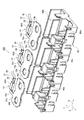
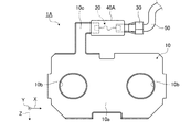
実施形態1に係る導体の接続構造および導電モジュールについて説明する。図1は、実施形態1に係る導体の接続構造が適用された導電モジュールの概略構成を示す分解斜視図である。図2は、実施形態1に係る導体の接続構造が適用された導電モジュールの概略構成を示す平面図である。図3は、実施形態1に係る導体の接続構造の概略構成を示す平面図である。図4は、実施形態1に係る導体の接続構造の概略構成を示す分解平面図である。図5は、実施形態1における可溶体の概略構成を示す斜視図である。
[Embodiment 1]
A conductor connection structure and a conductive module according to the first embodiment will be described. FIG. 1 is an exploded perspective view showing a schematic configuration of a conductive module to which a conductor connection structure according to
以下の説明において、図示のX方向は、本実施形態における導電モジュールの幅方向であり、電極端子および接続導体の配列方向である。Y方向は、本実施形態における導電モジュールの上下方向であり、X方向と直交する方向である。Z方向は、本実施形態における導電モジュールの奥行方向であり、X方向およびY方向と直交する方向である。なお、Y方向は鉛直方向に限らない。 In the following description, the X direction shown in the figure is the width direction of the conductive module in the present embodiment, and is the arrangement direction of the electrode terminals and connection conductors. The Y direction is the vertical direction of the conductive module in the present embodiment, and is a direction orthogonal to the X direction. The Z direction is a depth direction of the conductive module in the present embodiment, and is a direction orthogonal to the X direction and the Y direction. The Y direction is not limited to the vertical direction.
図1および図2に示す導電モジュール100は、複数の電池セル(不図示)からなる電池モジュール(不図示)に組み付けられるものである。電池モジュールは、例えば、電気自動車(EV)やハイブリッド車両(HV、PHV)に搭載され、駆動源である回転電機に電力を供給したり、回転電機が発生した電力を蓄電(充電)したりすることに用いられる。電池モジュールは、それぞれの電池セルにおける何れか一方の電極端子が一列に並べられ、かつ、他方の電極端子が一列に並べられるように、それぞれの電池セルを同一方向に配列したものである。電池モジュールは、同一方向に配列された複数の電極端子からなる電極端子群に対応して導電モジュール100が組み付けられ、複数の電池セルの電極端子(正極端子、負極端子)を導電モジュール100により直列接続あるいは並列接続することで、所望される電源としての機能を発揮する。導電モジュール100は、電池セルと後述する電池監視ユニット200とを電気的に接続させるものである。具体的には、導電モジュール100は、複数の導体1Aと、収容ケース60とを含んで構成される。
The
導体1Aは、接続導体10と、可溶体20と、中継端子30と、樹脂モールド部材40Aと、線状導体50とを含んで構成される。導体1Aは、接続導体10と線状導体50との間に可溶体20および中継端子30を接続し、これらが互いに電気的に接続して構成される接続構造を有する。
The
接続導体10は、例えばバスバーであり、同一方向に配列された複数の電池セルにおける電極端子群の少なくとも1つの電極端子に直接的に接続され、各電極端子の配列方向に沿って配列される。接続導体10は、平板状の金属等の導電性材料から成り、2つの貫通孔10bのいずれか一方または両方に電極端子を挿通させた上でネジ止めされて、電極端子に直接取り付けられる。なお、接続導体10は、電池セルの配列方向で隣り合う2つの電極端子に直接取付けられてもよい。接続導体10は、導電モジュール100において、収容ケース60に形成され、各電極端子の配列方向に沿って配列された複数の収容空間部60aにそれぞれ収容される。接続導体10は、図3および図4に示すように、接続導体本体10aと、複数の貫通孔10bと、接続部10cとを含んで構成される。
The
接続導体本体10aは、Y方向に貫通する複数の貫通孔10bを備える。各貫通孔10bは、電池セルから上方に突出した電極端子が挿入されるものであり、各電池セル2との接続部を残すように抜き加工によって形成される。接続部10cは、接続導体本体10aの端部からZ方向に延在し、かつ、Y方向から平面視したときにL字状または逆L字状に形成されている。接続部10cは、可溶体20に接続されている。
The connection conductor
可溶体20は、一方の端部が接続導体10に直に接続され、他方の端部が中継端子30を介して線状導体50に接続されている。つまり、可溶体20は、接続導体10と線状導体50との間に間接的に接続されている。可溶体20は、例えばヒューズであり、過電流が流れたときに溶断し、該当する電流経路を遮断する。すなわち、可溶体20は、接続導体10と線状導体50との間に過電流が流れたときに溶断し、この溶断によって線状導体50に接続されている電池監視ユニット200を保護する。可溶体20の過電流とは、例えば、予め設定された定格以上の電流である。つまり、可溶体20は、予め設定された定格以上の電流が流れたときに溶断する。可溶体20の定格電流は、保護する回路の電流に合わせてそれぞれ決められる。可溶体20は、図5に示すように、一対の端子20aと、この一対の端子20aの間に設けられた溶断部20bとで構成される。一対の端子20aのうち、一方の端子20aが接続導体10の接続部10cに接続され、他方の端子20aが中継端子30に接続される。一方の端子20aは、接続部10cとの間で半田付けや溶接などにより接続される。他方の接続部10cは、中継端子30との間で半田付けや溶接、加締めなどにより接続される。溶断部20bは、錫や鉛などの金属により細く、かつ、波状に形成されている。溶断部20bは、上述したように、予め設定された定格以上の電流が流れたときに溶断する。
One end of the
中継端子30は、一方の端部30aが可溶体20を介して接続導体10に接続され、他方の端部が線状導体50に接続されている。つまり、中継端子30は、可溶体20を接続導体10と線状導体50との間で間接的に接続する。中継端子30は、金属などの導電性材料で形成された接続端子であり、可溶体20と線状導体50とを物理的および電気的に接続するものである。中継端子30は、線状導体50と可溶体20とが対向した状態で、線状導体50、可溶体20の延在方向に沿って線状導体50と可溶体20とを接続する。中継端子30の一方の端部30aが可溶体20の端子20aに接続し、他方の端部が絶縁被覆を剥離して露出させた状態の線状導体50の端部に接続する。中継端子30の一方の端部30aは、可溶体20の端子20aに対して半田付け、溶接などにより接続する。中継端子30の他方の端部は、線状導体50の端部に対して圧着、半田付け若しくは溶接などにより接続する。
The
樹脂モールド部材40Aは、例えば、絶縁性を有する合成樹脂で形成される。樹脂モールド部材40Aは、図3に示すように、可溶体20、接続導体10の一部、および中継端子30の一部を内在する。すなわち、樹脂モールド部材40Aは、可溶体20の表面全部、接続導体10の接続部10cの表面の一部、および中継端子30の端部30aの表面の一部を覆うように形成される。この樹脂モールド部材40Aは、接続導体10、可溶体20、中継端子30、および線状導体50を一体的に成形する。樹脂モールド部材40Aの成形方法としては、例えば、金型を用いたインサート成形が挙げられる。この場合、まず、接続導体10と中継端子30との間を可溶体20を介して溶接などにより接続した成形対象物を作製し、当該成形対象物を成形金型の内部にセットする。次に、成形金型を閉じて内部に溶融した樹脂を流し込み、固まるまで待って成形金型を開き、成形対象物を取り出す。成形対象物に形成された樹脂モールド部材40Aから不要な樹脂を切り離す。
The
線状導体50は、図2に示すように、電池監視ユニット200に接続される。具体的には、線状導体50は、絶縁被覆を剥離して露出させた状態の一方の端部が中継端子30の他方の端部に接続され、他方の端部が電池監視ユニット200に接続される。電池監視ユニット200は、複数の電池セルの電池状態を監視する。電池監視ユニット200は、例えば電圧検出装置であり、複数の電池セルの端子電圧を検出する。この場合、線状導体50は、電圧検出線を構成する。電池監視ユニット200は、例えば、オペアンプ、AD変換器などで構成され、電池セルの端子電圧を所定周期でサンプリングしてデジタル信号に変換して出力する。電池監視ユニット200は、車両に搭載されている不図示のECU(Engine Control Unit)に接続され、当該ECUに電池セルの端子電圧の値を出力する。
The
収容ケース60は、例えば絶縁性を有する合成樹脂などで形成され、複数の導体1Aを収容する。収容ケース60は、複数の接続導体10をそれぞれ収容する中空状の複数の収容空間部60aと、複数の線状導体50を配線可能な中空状の配線空間部60bとを備える。収容空間部60aは、可溶体20および接続導体10の一部が内在する樹脂モールド部材40Aと一体的に構成される接続導体10をY方向に設けられた開口から収容する。配線空間部60bは、収容空間部60aに収容された接続導体10から伸びる線状導体50をY方向に設けられた開口から収容する。
The
以上説明した実施形態1の導体1Aの接続構造は、同一方向に配列された複数の電池セルにおける電極端子群の少なくとも1つの電極端子に直接的に接続される接続導体10と、複数の電池セルの電池状態を監視する電池監視ユニット200に接続される線状導体50と、接続導体10と線状導体50との間に間接的に接続され、かつ、接続導体10と線状導体50との間を過電流が流れたときに溶断する可溶体20と、可溶体20、接続導体10の一部、および中継端子30の一部を内在する絶縁性の樹脂モールド部材40Aとを備える。
The connection structure of the
また、以上説明した実施形態1の導電モジュール100は、同一方向に配列された複数の電池セルにおける電極端子群の少なくとも1つの電極端子に直接的に接続される接続導体10と、複数の電池セルの電池状態を監視する電池監視ユニット200に接続される線状導体50と、接続導体10と線状導体50との間に間接的に接続され、かつ、接続導体10と線状導体50との間を過電流が流れたときに溶断する可溶体20と、可溶体20、接続導体10の一部、および中継端子30の一部を内在する樹脂モールド部材40Aとを備え、接続導体10を少なくとも1つの電極端子に対応して複数備える。複数の接続導体10は、絶縁性の収容ケース60に形成され、かつ、各電極端子の配列方向に沿って配列された複数の収容空間部60aにそれぞれ収容される。
In addition, the
上記構成の導体1Aの接続構造および導電モジュール100によれば、接続導体10が、中継端子を介することなく可溶体20に直に接続されているので、接続導体10と線状導体50との間を接続する中継端子の数を削減して、導体1Aおよび導電モジュール100の小型化、軽量化を図ると共に、部品コストを抑えることができる。また、中継端子の数および電気的な接点数の減少により電池監視ユニット200を流れる抵抗値が低下し、電池セルの端子電圧を精度良く検出することが可能となる。また、接続導体10と線状導体50との間に可溶体20が接続されているので、過電流に対する導体1Aおよび電池監視ユニット200の保護が可能となる。さらに、導体1Aの接続構造および導電モジュール100は、可溶体20および接続導体10の一部および中継端子30の一部を樹脂モールド部材40Aに内在させるので、接続導体10、可溶体20、および中継端子30を1つの部品として扱うことが可能となり、複数の導体1Aを導電モジュール100に組み付ける時などの組み立て時に、収容ケース60に対するヒューズや中継端子の組み付け工程が不要となり、組み立て時における作業容易性を向上することができる。
According to the connection structure of the
[実施形態2]
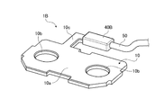
次に、実施形態2に係る導体の接続構造および導電モジュールについて説明する。図6は、実施形態2に係る導体の接続構造の概略構成を示す斜視図である。図7は、実施形態2に係る導体の接続構造の概略構成を示す平面図である。図8は、実施形態2に係る導体の接続構造の概略構成を示す分解平面図である。
[Embodiment 2]
Next, the conductor connection structure and the conductive module according to the second embodiment will be described. FIG. 6 is a perspective view illustrating a schematic configuration of a conductor connection structure according to the second embodiment. FIG. 7 is a plan view illustrating a schematic configuration of a conductor connection structure according to the second embodiment. FIG. 8 is an exploded plan view showing a schematic configuration of a conductor connection structure according to the second embodiment.
実施形態2に係る導体1Bの接続構造および導電モジュール100は、図6〜図8に示すように、接続導体10と線状導体50との間に可溶体20のみを接続している点で上記実施形態1に係る導体1Aの接続構造および導電モジュール100と異なる。なお、以下の説明において、上記実施形態1と共通する構成については同一の符号を付して、その説明を省略する。
The connection structure of the
導体1Bは、接続導体10と、可溶体20と、樹脂モールド部材40Bと、線状導体50とを含んで構成される。導体1Bは、接続導体10と線状導体50との間に可溶体20を接続し、これらが互いに電気的に接続して構成される接続構造を有する。
The
実施形態2における可溶体20は、一方の端部が接続導体10に直に接続され、他方の端部が線状導体50に直に接続されている。つまり、可溶体20は、接続導体10と線状導体50との間に直接的に接続されている。具体的には、可溶体20は、一方の端子20aが接続導体10の接続部10cに接続され、他方の端子20aが線状導体50に接続される。一方の端子20aは、接続部10cとの間で半田付けや溶接などにより接続される。他方の端子20aは、線状導体50との間で半田付けや溶接、加締めなどにより接続される。
In the
樹脂モールド部材40Bは、図7に示すように、可溶体20、接続導体10の一部、および線状導体50の端部50aを内在する。すなわち、樹脂モールド部材40Bは、可溶体20の表面全部、接続導体10の接続部10cの表面の一部、および線状導体50の端部50aの表面を覆うように形成される。この樹脂モールド部材40Bは、接続導体10、可溶体20、および線状導体50を一体的に成形する。なお、樹脂モールド部材40Bの成形方法は、上記実施形態1と同様である。
As shown in FIG. 7, the resin mold member 40 </ b> B includes the
実施形態2における線状導体50は、絶縁被覆を剥離して露出させた状態の一方の端部50aが可溶体20の他方の端子20aに接続され、他方の端部が電池監視ユニット200に接続される。
In the
以上説明した実施形態2の導体1Bの接続構造は、同一方向に配列された複数の電池セルにおける電極端子群の少なくとも1つの電極端子に直接的に接続される接続導体10と、複数の電池セルの電池状態を監視する電池監視ユニット200に接続される線状導体50と、接続導体10と線状導体50との間に直接的に接続され、かつ、接続導体10と線状導体50との間を過電流が流れたときに溶断する可溶体20と、可溶体20、接続導体10の一部、および線状導体50の端部50aを内在する絶縁性の樹脂モールド部材40Bとを備える。
The connection structure of the
また、以上説明した実施形態2の導電モジュール100は、同一方向に配列された複数の電池セルにおける電極端子群の少なくとも1つの電極端子に直接的に接続される接続導体10と、複数の電池セルの電池状態を監視する電池監視ユニット200に接続される線状導体50と、接続導体10と線状導体50との間に直接的に接続され、かつ、接続導体10と線状導体50との間を過電流が流れたときに溶断する可溶体20と、可溶体20、接続導体10の一部、および線状導体50の端部50aを内在する樹脂モールド部材40Bとを備え、接続導体10を少なくとも1つの電極端子に対応して複数備える。複数の接続導体10は、絶縁性の収容ケース60に形成され、かつ、各電極端子の配列方向に沿って配列された複数の収容空間部60aにそれぞれ収容される。
In addition, the
上記構成の導体1Bの接続構造および導電モジュール100によれば、接続導体10が、中継端子30を介することなく可溶体20に直に接続され、かつ、可溶体20を介して直に線状導体50に接続されているので、上記実施形態1の導体1Aの接続構造および導電モジュール100による効果をさらに得ることができる。
According to the connection structure of the
なお、上記実施形態1,2では、接続導体10をバスバーとしているが、これに限定されるものではない。すなわち、接続導体10は、同一方向に配列された複数の電池セルにおける電極端子群の少なくとも1つの電極端子にバスバーを介して間接的に接続された導体であってもよい。この場合、接続導体10は、そのバスバーに対して物理的、かつ、電気的に接続される。この接続導体10とバスバーとの間は、例えば、嵌合構造、溶接やネジ止め等を用いて接続される。
In the first and second embodiments, the
また、上記実施形態1,2において、接続導体10は、接続導体本体10aの端部からZ方向に延在し、かつ、Y方向から平面視したときにL字状または逆L字状に形成される接続部10cに可溶体20が接続されているが、これに限定されず、接続導体本体10aに直に可溶体20が接続される構造であってもよい。この場合、樹脂モールド部材40A,40Bは、可溶体20の表面全部、接続導体10の表面の一部、中継端子30の端部30aの表面の一部または線状導体50の端部50aの表面の一部を覆うように形成される。
In the first and second embodiments, the
また、上記実施形態1,2において、電池監視ユニット200の回路構成などは特に限定されない。電池監視ユニット200は、例えば、各単電池の端子電圧や組電池全体の端子電圧を検出するように構成されていてもよい。
In the first and second embodiments, the circuit configuration of the
また、上記実施形態1,2において、可溶体20は、予め設定された定格以上の電流が流れたときに溶断するものであれば、図示の形状や構成に限らない。
In the first and second embodiments, the
1A,1B 導体
10 接続導体
10a 接続導体本体
10b 貫通孔
10c 接続部
20 可溶体
20a 端子
20b 溶断部
30 中継端子
40A,40B 樹脂モールド部材
50 線状導体
60 収容ケース
60a 収容空間部
60b 配線空間部
100 導電モジュール
200 電池監視ユニット
DESCRIPTION OF
Claims (4)
前記複数の電池セルの電池状態を監視する電池監視ユニットに接続される線状導体と、
前記接続導体と前記線状導体との間に直接的または間接的に接続され、かつ、前記接続導体と前記線状導体との間を過電流が流れたときに溶断する可溶体と、
前記可溶体および前記接続導体の一部を内在する絶縁性の樹脂モールド部材と、
を備えることを特徴とする導体の接続構造。 A connection conductor connected directly or indirectly to at least one electrode terminal of the electrode terminal group in the plurality of battery cells arranged in the same direction;
A linear conductor connected to a battery monitoring unit for monitoring a battery state of the plurality of battery cells;
A fusible body that is directly or indirectly connected between the connection conductor and the linear conductor, and that melts when an overcurrent flows between the connection conductor and the linear conductor; and
An insulative resin mold member that includes a part of the fusible body and the connection conductor;
A conductor connection structure comprising:
前記樹脂モールド部材はさらに、前記中継端子の一部を内在する
請求項1に記載の導体の接続構造。 The fusible body is connected to the linear conductor via a metal relay terminal,
The conductor connection structure according to claim 1, wherein the resin mold member further includes a part of the relay terminal.
前記一対の端子のうちの一方には前記接続導体が接続され、他方には前記線状導体または前記中継端子が接続される
請求項2に記載の導体の接続構造。 The fusible body is composed of a pair of terminals and a fusing part provided between the pair of terminals,
The conductor connection structure according to claim 2, wherein the connection conductor is connected to one of the pair of terminals, and the linear conductor or the relay terminal is connected to the other.
前記複数の電池セルの電池状態を監視する電池監視ユニットに接続される線状導体と、
前記接続導体と前記線状導体との間に直接的または間接的に接続され、かつ、前記接続導体と前記線状導体との間を過電流が流れたときに溶断する可溶体と、
前記可溶体および前記接続導体の一部を内在する絶縁性の樹脂モールド部材と、
を備える導体を少なくとも1つの前記電極端子に対応して複数備え、
複数の前記接続導体は、絶縁性の収容ケースに形成され、かつ、各前記電極端子の配列方向に沿って配列された複数の収容空間部にそれぞれ収容される
ことを特徴とする導電モジュール。 A connection conductor connected directly or indirectly to at least one electrode terminal of the electrode terminal group in the plurality of battery cells arranged in the same direction;
A linear conductor connected to a battery monitoring unit for monitoring a battery state of the plurality of battery cells;
A fusible body that is directly or indirectly connected between the connection conductor and the linear conductor, and that melts when an overcurrent flows between the connection conductor and the linear conductor; and
An insulative resin mold member that includes a part of the fusible body and the connection conductor;
A plurality of conductors corresponding to at least one of the electrode terminals,
The plurality of connection conductors are formed in an insulating housing case, and are respectively housed in a plurality of housing spaces arranged along the arrangement direction of the electrode terminals.
Priority Applications (4)
| Application Number | Priority Date | Filing Date | Title |
|---|---|---|---|
| JP2016239796A JP6524051B2 (en) | 2016-12-09 | 2016-12-09 | Conductor connection structure and conductive module |
| US15/793,926 US11043721B2 (en) | 2016-12-09 | 2017-10-25 | Connection structure of conductor and conductive module |
| DE102017221415.5A DE102017221415A1 (en) | 2016-12-09 | 2017-11-29 | CONNECTING STRUCTURE OF A LEADER AND A CONDUCTIVE MODULE |
| CN201711293656.7A CN108258178B (en) | 2016-12-09 | 2017-12-08 | Conductor connection structure and conductive module |
Applications Claiming Priority (1)
| Application Number | Priority Date | Filing Date | Title |
|---|---|---|---|
| JP2016239796A JP6524051B2 (en) | 2016-12-09 | 2016-12-09 | Conductor connection structure and conductive module |
Publications (2)
| Publication Number | Publication Date |
|---|---|
| JP2018097987A true JP2018097987A (en) | 2018-06-21 |
| JP6524051B2 JP6524051B2 (en) | 2019-06-05 |
Family
ID=62201574
Family Applications (1)
| Application Number | Title | Priority Date | Filing Date |
|---|---|---|---|
| JP2016239796A Active JP6524051B2 (en) | 2016-12-09 | 2016-12-09 | Conductor connection structure and conductive module |
Country Status (4)
| Country | Link |
|---|---|
| US (1) | US11043721B2 (en) |
| JP (1) | JP6524051B2 (en) |
| CN (1) | CN108258178B (en) |
| DE (1) | DE102017221415A1 (en) |
Cited By (6)
| Publication number | Priority date | Publication date | Assignee | Title |
|---|---|---|---|---|
| JP2018097988A (en) * | 2016-12-09 | 2018-06-21 | 矢崎総業株式会社 | Voltage detection structure and voltage detection module |
| WO2021235174A1 (en) * | 2020-05-21 | 2021-11-25 | 株式会社デンソー | Connection terminal and terminal module containing same |
| US11569551B2 (en) | 2020-04-07 | 2023-01-31 | Yazaki Corporation | Busbar module |
| WO2023037888A1 (en) * | 2021-09-09 | 2023-03-16 | 株式会社オートネットワーク技術研究所 | Wiring module |
| WO2023037889A1 (en) * | 2021-09-09 | 2023-03-16 | 株式会社オートネットワーク技術研究所 | Wiring module |
| WO2023153347A1 (en) * | 2022-02-14 | 2023-08-17 | 株式会社オートネットワーク技術研究所 | Wiring module |
Families Citing this family (6)
| Publication number | Priority date | Publication date | Assignee | Title |
|---|---|---|---|---|
| WO2018221004A1 (en) * | 2017-05-29 | 2018-12-06 | 三洋電機株式会社 | Battery pack |
| JP6947139B2 (en) * | 2018-08-29 | 2021-10-13 | 株式会社オートネットワーク技術研究所 | Overcurrent cutoff unit |
| CN114729956A (en) * | 2019-11-15 | 2022-07-08 | 阿尔卑斯阿尔派株式会社 | Current detection device |
| KR102344019B1 (en) * | 2019-12-23 | 2021-12-28 | 대산전자(주) | Busbar by applying fuse |
| DE102020111098A1 (en) | 2020-04-23 | 2021-10-28 | Pollmann International Gmbh | Component carrier for cell connectors |
| KR20210139001A (en) * | 2020-05-13 | 2021-11-22 | 주식회사 엘지에너지솔루션 | Battery Pack With Fuse-Box Bracket of Preventing Short Circuit |
Citations (5)
| Publication number | Priority date | Publication date | Assignee | Title |
|---|---|---|---|---|
| JPH10270006A (en) * | 1997-03-24 | 1998-10-09 | Toyota Motor Corp | Battery power supply and end plate used therein |
| JPH11120986A (en) * | 1997-10-13 | 1999-04-30 | Toyota Motor Corp | Battery holder connecting plate and its manufacture |
| JP2001110396A (en) * | 1999-10-05 | 2001-04-20 | Yazaki Corp | Device and method for machining terminal of battery connecting plate |
| JP2018097988A (en) * | 2016-12-09 | 2018-06-21 | 矢崎総業株式会社 | Voltage detection structure and voltage detection module |
| JP2018097986A (en) * | 2016-12-09 | 2018-06-21 | 矢崎総業株式会社 | Fixing structure of conductor unit |
Family Cites Families (16)
| Publication number | Priority date | Publication date | Assignee | Title |
|---|---|---|---|---|
| EP1376734A3 (en) | 1997-03-24 | 2004-11-24 | Matsushita Electric Industrial Co., Ltd. | Cooling device for battery power source |
| CN100492574C (en) * | 2001-06-05 | 2009-05-27 | 松下电器产业株式会社 | Temperature fuse, and battery using same |
| JP4267471B2 (en) * | 2004-02-03 | 2009-05-27 | 矢崎総業株式会社 | Fuse unit |
| US9024572B2 (en) * | 2009-03-31 | 2015-05-05 | Sanyo Electric Co., Ltd. | Battery module, battery system and electric vehicle |
| JP5298093B2 (en) * | 2010-09-03 | 2013-09-25 | 日立ビークルエナジー株式会社 | Power storage device |
| CN103563122B (en) * | 2011-05-18 | 2016-10-12 | 日立汽车系统株式会社 | Electrical storage device |
| US8622634B2 (en) * | 2011-07-29 | 2014-01-07 | Corning Cable Systems Llc | Optical fiber assemblies and methods of fabricating optical fiber assemblies |
| JP5704406B2 (en) * | 2011-11-30 | 2015-04-22 | 株式会社オートネットワーク技術研究所 | Connector and wire harness |
| KR20130118539A (en) * | 2012-04-20 | 2013-10-30 | 삼성에스디아이 주식회사 | Battery pack |
| JP6370586B2 (en) * | 2014-04-18 | 2018-08-08 | 矢崎総業株式会社 | Battery connector and battery pack provided with the same |
| JP6143108B2 (en) * | 2014-05-07 | 2017-06-07 | 株式会社オートネットワーク技術研究所 | Power storage module |
| JP6237450B2 (en) * | 2014-05-07 | 2017-11-29 | 株式会社オートネットワーク技術研究所 | Power storage module |
| JP2016018741A (en) * | 2014-07-10 | 2016-02-01 | 矢崎総業株式会社 | Battery wiring module |
| WO2016017683A1 (en) | 2014-07-30 | 2016-02-04 | 株式会社オートネットワーク技術研究所 | Power storage module |
| JP6085589B2 (en) * | 2014-12-15 | 2017-02-22 | 矢崎総業株式会社 | Battery wiring module |
| JP6571627B2 (en) * | 2016-11-18 | 2019-09-04 | 矢崎総業株式会社 | Conductive module and battery pack |
-
2016
- 2016-12-09 JP JP2016239796A patent/JP6524051B2/en active Active
-
2017
- 2017-10-25 US US15/793,926 patent/US11043721B2/en active Active
- 2017-11-29 DE DE102017221415.5A patent/DE102017221415A1/en active Pending
- 2017-12-08 CN CN201711293656.7A patent/CN108258178B/en active Active
Patent Citations (5)
| Publication number | Priority date | Publication date | Assignee | Title |
|---|---|---|---|---|
| JPH10270006A (en) * | 1997-03-24 | 1998-10-09 | Toyota Motor Corp | Battery power supply and end plate used therein |
| JPH11120986A (en) * | 1997-10-13 | 1999-04-30 | Toyota Motor Corp | Battery holder connecting plate and its manufacture |
| JP2001110396A (en) * | 1999-10-05 | 2001-04-20 | Yazaki Corp | Device and method for machining terminal of battery connecting plate |
| JP2018097988A (en) * | 2016-12-09 | 2018-06-21 | 矢崎総業株式会社 | Voltage detection structure and voltage detection module |
| JP2018097986A (en) * | 2016-12-09 | 2018-06-21 | 矢崎総業株式会社 | Fixing structure of conductor unit |
Cited By (8)
| Publication number | Priority date | Publication date | Assignee | Title |
|---|---|---|---|---|
| JP2018097988A (en) * | 2016-12-09 | 2018-06-21 | 矢崎総業株式会社 | Voltage detection structure and voltage detection module |
| US11569551B2 (en) | 2020-04-07 | 2023-01-31 | Yazaki Corporation | Busbar module |
| WO2021235174A1 (en) * | 2020-05-21 | 2021-11-25 | 株式会社デンソー | Connection terminal and terminal module containing same |
| JP2021184338A (en) * | 2020-05-21 | 2021-12-02 | 株式会社デンソー | Connection terminal and terminal module including the same |
| JP7243680B2 (en) | 2020-05-21 | 2023-03-22 | 株式会社デンソー | Connection terminals and terminal modules containing them |
| WO2023037888A1 (en) * | 2021-09-09 | 2023-03-16 | 株式会社オートネットワーク技術研究所 | Wiring module |
| WO2023037889A1 (en) * | 2021-09-09 | 2023-03-16 | 株式会社オートネットワーク技術研究所 | Wiring module |
| WO2023153347A1 (en) * | 2022-02-14 | 2023-08-17 | 株式会社オートネットワーク技術研究所 | Wiring module |
Also Published As
| Publication number | Publication date |
|---|---|
| US20180166673A1 (en) | 2018-06-14 |
| CN108258178A (en) | 2018-07-06 |
| JP6524051B2 (en) | 2019-06-05 |
| DE102017221415A1 (en) | 2018-06-14 |
| US11043721B2 (en) | 2021-06-22 |
| CN108258178B (en) | 2021-03-05 |
| DE102017221415A8 (en) | 2018-07-26 |
Similar Documents
| Publication | Publication Date | Title |
|---|---|---|
| JP6524051B2 (en) | Conductor connection structure and conductive module | |
| JP6510482B2 (en) | Fixing structure of conductor unit | |
| US8721367B2 (en) | Fuse unit | |
| JP6581958B2 (en) | Voltage detection structure and voltage detection module | |
| JP6624427B2 (en) | Power storage module | |
| CN109037506B (en) | Battery pack | |
| EP3367473B1 (en) | Wiring module | |
| CN108701800B (en) | Wiring module | |
| JP2017098038A (en) | Bus bar module and battery pack | |
| JP2012005162A (en) | Electric connection box | |
| US9490094B2 (en) | Overcurrent protection apparatus | |
| WO2011155369A1 (en) | Battery connecting plate | |
| US20180047952A1 (en) | Electricity storage pack | |
| JP2017098108A (en) | Wiring module | |
| WO2023153347A1 (en) | Wiring module | |
| JP7177502B2 (en) | Multiple-type fuse and manufacturing method of the multiple-type fuse | |
| JP4163593B2 (en) | Fuse unit | |
| JP4163592B2 (en) | Fuse unit | |
| JP2005276494A (en) | Fuse holder and fuse unit | |
| JP2015076377A (en) | Fuse box |
Legal Events
| Date | Code | Title | Description |
|---|---|---|---|
| A977 | Report on retrieval |
Free format text: JAPANESE INTERMEDIATE CODE: A971007 Effective date: 20190221 |
|
| A131 | Notification of reasons for refusal |
Free format text: JAPANESE INTERMEDIATE CODE: A131 Effective date: 20190226 |
|
| A521 | Request for written amendment filed |
Free format text: JAPANESE INTERMEDIATE CODE: A523 Effective date: 20190419 |
|
| TRDD | Decision of grant or rejection written | ||
| A01 | Written decision to grant a patent or to grant a registration (utility model) |
Free format text: JAPANESE INTERMEDIATE CODE: A01 Effective date: 20190423 |
|
| A61 | First payment of annual fees (during grant procedure) |
Free format text: JAPANESE INTERMEDIATE CODE: A61 Effective date: 20190426 |
|
| R150 | Certificate of patent or registration of utility model |
Ref document number: 6524051 Country of ref document: JP Free format text: JAPANESE INTERMEDIATE CODE: R150 |
|
| R250 | Receipt of annual fees |
Free format text: JAPANESE INTERMEDIATE CODE: R250 |
|
| R250 | Receipt of annual fees |
Free format text: JAPANESE INTERMEDIATE CODE: R250 |
|
| S531 | Written request for registration of change of domicile |
Free format text: JAPANESE INTERMEDIATE CODE: R313531 |
|
| R350 | Written notification of registration of transfer |
Free format text: JAPANESE INTERMEDIATE CODE: R350 |