WO2021235174A1 - Connection terminal and terminal module containing same - Google Patents
Connection terminal and terminal module containing same Download PDFInfo
- Publication number
- WO2021235174A1 WO2021235174A1 PCT/JP2021/016475 JP2021016475W WO2021235174A1 WO 2021235174 A1 WO2021235174 A1 WO 2021235174A1 JP 2021016475 W JP2021016475 W JP 2021016475W WO 2021235174 A1 WO2021235174 A1 WO 2021235174A1
- Authority
- WO
- WIPO (PCT)
- Prior art keywords
- terminal
- connection
- spring
- connection portion
- terminal connection
- Prior art date
Links
Images


Classifications
-
- H—ELECTRICITY
- H01—ELECTRIC ELEMENTS
- H01R—ELECTRICALLY-CONDUCTIVE CONNECTIONS; STRUCTURAL ASSOCIATIONS OF A PLURALITY OF MUTUALLY-INSULATED ELECTRICAL CONNECTING ELEMENTS; COUPLING DEVICES; CURRENT COLLECTORS
- H01R9/00—Structural associations of a plurality of mutually-insulated electrical connecting elements, e.g. terminal strips or terminal blocks; Terminals or binding posts mounted upon a base or in a case; Bases therefor
- H01R9/16—Fastening of connecting parts to base or case; Insulating connecting parts from base or case
-
- H—ELECTRICITY
- H01—ELECTRIC ELEMENTS
- H01M—PROCESSES OR MEANS, e.g. BATTERIES, FOR THE DIRECT CONVERSION OF CHEMICAL ENERGY INTO ELECTRICAL ENERGY
- H01M50/00—Constructional details or processes of manufacture of the non-active parts of electrochemical cells other than fuel cells, e.g. hybrid cells
- H01M50/20—Mountings; Secondary casings or frames; Racks, modules or packs; Suspension devices; Shock absorbers; Transport or carrying devices; Holders
-
- H—ELECTRICITY
- H01—ELECTRIC ELEMENTS
- H01M—PROCESSES OR MEANS, e.g. BATTERIES, FOR THE DIRECT CONVERSION OF CHEMICAL ENERGY INTO ELECTRICAL ENERGY
- H01M50/00—Constructional details or processes of manufacture of the non-active parts of electrochemical cells other than fuel cells, e.g. hybrid cells
- H01M50/50—Current conducting connections for cells or batteries
- H01M50/543—Terminals
-
- H—ELECTRICITY
- H01—ELECTRIC ELEMENTS
- H01M—PROCESSES OR MEANS, e.g. BATTERIES, FOR THE DIRECT CONVERSION OF CHEMICAL ENERGY INTO ELECTRICAL ENERGY
- H01M50/00—Constructional details or processes of manufacture of the non-active parts of electrochemical cells other than fuel cells, e.g. hybrid cells
- H01M50/50—Current conducting connections for cells or batteries
- H01M50/572—Means for preventing undesired use or discharge
-
- H—ELECTRICITY
- H01—ELECTRIC ELEMENTS
- H01R—ELECTRICALLY-CONDUCTIVE CONNECTIONS; STRUCTURAL ASSOCIATIONS OF A PLURALITY OF MUTUALLY-INSULATED ELECTRICAL CONNECTING ELEMENTS; COUPLING DEVICES; CURRENT COLLECTORS
- H01R11/00—Individual connecting elements providing two or more spaced connecting locations for conductive members which are, or may be, thereby interconnected, e.g. end pieces for wires or cables supported by the wire or cable and having means for facilitating electrical connection to some other wire, terminal, or conductive member, blocks of binding posts
- H01R11/11—End pieces or tapping pieces for wires, supported by the wire and for facilitating electrical connection to some other wire, terminal or conductive member
- H01R11/12—End pieces terminating in an eye, hook, or fork
-
- H—ELECTRICITY
- H01—ELECTRIC ELEMENTS
- H01R—ELECTRICALLY-CONDUCTIVE CONNECTIONS; STRUCTURAL ASSOCIATIONS OF A PLURALITY OF MUTUALLY-INSULATED ELECTRICAL CONNECTING ELEMENTS; COUPLING DEVICES; CURRENT COLLECTORS
- H01R4/00—Electrically-conductive connections between two or more conductive members in direct contact, i.e. touching one another; Means for effecting or maintaining such contact; Electrically-conductive connections having two or more spaced connecting locations for conductors and using contact members penetrating insulation
- H01R4/28—Clamped connections, spring connections
- H01R4/30—Clamped connections, spring connections utilising a screw or nut clamping member
- H01R4/34—Conductive members located under head of screw
-
- H—ELECTRICITY
- H01—ELECTRIC ELEMENTS
- H01R—ELECTRICALLY-CONDUCTIVE CONNECTIONS; STRUCTURAL ASSOCIATIONS OF A PLURALITY OF MUTUALLY-INSULATED ELECTRICAL CONNECTING ELEMENTS; COUPLING DEVICES; CURRENT COLLECTORS
- H01R9/00—Structural associations of a plurality of mutually-insulated electrical connecting elements, e.g. terminal strips or terminal blocks; Terminals or binding posts mounted upon a base or in a case; Bases therefor
- H01R9/22—Bases, e.g. strip, block, panel
- H01R9/24—Terminal blocks
- H01R9/2425—Structural association with built-in components
- H01R9/245—Structural association with built-in components with built-in fuse
-
- Y—GENERAL TAGGING OF NEW TECHNOLOGICAL DEVELOPMENTS; GENERAL TAGGING OF CROSS-SECTIONAL TECHNOLOGIES SPANNING OVER SEVERAL SECTIONS OF THE IPC; TECHNICAL SUBJECTS COVERED BY FORMER USPC CROSS-REFERENCE ART COLLECTIONS [XRACs] AND DIGESTS
- Y02—TECHNOLOGIES OR APPLICATIONS FOR MITIGATION OR ADAPTATION AGAINST CLIMATE CHANGE
- Y02E—REDUCTION OF GREENHOUSE GAS [GHG] EMISSIONS, RELATED TO ENERGY GENERATION, TRANSMISSION OR DISTRIBUTION
- Y02E60/00—Enabling technologies; Technologies with a potential or indirect contribution to GHG emissions mitigation
- Y02E60/10—Energy storage using batteries
Definitions
- connection terminal connected to an electronic device and a terminal module including the connection terminal.
- Patent Document 1 shows a battery connection plate.
- the battery connection plate includes a plate body mounted on a plurality of batteries, a terminal mounted on the plate body, and a terminal for connecting the battery and an electronic component.
- An object of the present disclosure is to provide a connection terminal in which a defect is suppressed in electrical connection with a lead terminal, and a terminal module including the connection terminal.
- connection terminal is a connection terminal provided in the resin case and to which the lead terminal of the electronic element is connected by a conductive adhesive.
- the terminal connection part to which the lead terminal is connected and It has a spring portion that is integrally connected to the terminal connection portion and generates an elastic force for fixing the terminal connection portion to the resin case.
- the terminal module includes a resin case and The connection terminal fixed to the resin case and A terminal module having an electronic element to which a lead terminal is connected to a connection terminal by a conductive adhesive.
- the connection terminal is The terminal connection part to which the lead terminal is connected and It has a spring portion that is integrally connected to the terminal connection portion and generates an elastic force for fixing the terminal connection portion to the resin case.
- the vibration of the terminal connection portion is suppressed.
- the vibration of the terminal connection portion suppresses the action of stress on the conductive adhesive that connects the terminal connection portion and the lead terminal. As a result, it is possible to prevent an electrical connection failure between the terminal connection portion and the lead terminal.
- FIG. 2 is an enlarged perspective view of a region A surrounded by a solid line in FIG. 2.
- It is a top view of a series bus bar. It is a side view of a series bus bar. It is a top view of the 1st frame part. It is a side view of the 1st frame part. It is a top view of the 2nd frame part. It is a side view of the 2nd frame part. It is a top view of the first detection terminal. It is a side view of the 1st detection terminal. It is a top view of the 2nd detection terminal. It is a side view of the 2nd detection terminal.
- FIG. 16 is a top view of a fuse. It is a side view of a fuse. It is a partial top view of a wiring passage. 16 is a cross-sectional view taken along the line XVII-XVII shown in FIG. It is a top view which shows the modification of the 1st frame part. It is sectional drawing for demonstrating the fixed state of a detection terminal.
- FIGS. 4 to 17 schematically show various components of the battery pack.
- the battery pack 100 of the present embodiment is applied to an electric vehicle such as an electric vehicle or a plug-in hybrid vehicle.
- the three directions that are orthogonal to each other are referred to as the x direction, the y direction, and the z direction.
- the description of "direction” is omitted, and the description is simply x, y, z.
- FIG. 1 shows the battery pack 100.
- a plurality of battery packs 100 are mounted on the vehicle.
- a plurality of battery packs 100 are connected in series or in parallel by a wire harness or the like. This constitutes an in-vehicle power supply.
- the in-vehicle power supply functions to supply electric power to the electric load of the vehicle.
- An in-vehicle power supply may be configured by one battery pack 100.
- the vehicle duct is connected to the battery pack 100.
- a fluid for adjusting the temperature of a plurality of battery cells 210 included in the battery pack 100 is supplied to the battery pack 100 from this duct. As a result, an excessive temperature change of the battery cell 210 is suppressed.
- the temperature of the battery pack 100 may be adjusted by the cooling water circulating in the vehicle.
- the space under the front seat of the vehicle, the space under the rear seat, and the space between the rear seat and the trunk room can be appropriately adopted.
- the battery pack 100 has a battery module 200, a bus module 300, and a cover 400.
- the battery module 200 has a plurality of battery cells 210 and a battery case 220.
- the bus bar module 300 has a bus bar case 310, a bus bar 330, a sensor 350, a wiring case 370, and a monitoring board 390.
- the plurality of battery cells 210 are housed in the battery case 220.
- the opening side of the battery case 220 of the plurality of battery cells 210 is covered by the bus module 300.
- the bus module 300 is covered by the cover 400.
- the bus module 300 includes a terminal module.
- Each of the plurality of battery cells 210 is a secondary battery.
- the secondary battery that can be adopted in the battery cell 210 include a lithium ion secondary battery, a nickel hydrogen secondary battery, and an organic radical battery. These secondary batteries generate an electromotive voltage by a chemical reaction.
- the battery cell 210 has a power generation element and a metal case for accommodating the power generation element.
- the metal case has a flat plate shape with a thin thickness in the y direction.
- the metal case has a first end face 210a and a second end face 210b arranged in the z direction.
- the metal case has a first main surface and a second main surface arranged in the y direction, and a first side surface and a second side surface arranged in the x direction. Of the six surfaces provided by these metal cases, the first main surface and the second main surface have a larger area than the other four surfaces.
- a negative electrode terminal 211 and a positive electrode terminal 212 are formed on the first end surface 210a of the metal case.
- the negative electrode terminal 211 and the positive electrode terminal 212 are arranged so as to be separated from each other in the x direction.
- the negative electrode terminal 211 is located on the first side surface side.
- the positive electrode terminal 212 is located on the second side surface side.
- the battery case 220 has a bottom wall 221 and a side wall 222.
- the bottom wall 221 and the side wall 222 are integrally connected.
- the bottom wall 221 and the side wall 222 are each made of an insulating resin material.
- the bottom wall 221 has a flat shape with a thin thickness in the z direction.
- the bottom wall 221 has an inner bottom surface 221a arranged apart from each other in the z direction and an outer bottom surface on the back side thereof.
- the side wall 222 stands up from the inner bottom surface 221a in the z direction.
- the side wall 222 extends along the edge of the inner bottom surface 221a and forms an annular shape in the circumferential direction around the z direction.
- the side wall 222 has a left side wall 223 and a right side wall 224 arranged apart from each other in the y direction, and a front side wall 225 and a rear side wall 226 arranged apart from each other in the x direction.
- the left side wall 223, the front side wall 225, the right side wall 224, and the rear side wall 226 are connected in this order in the circumferential direction around the z direction.
- the side wall 222 forms an annular shape in the circumferential direction around the z direction.
- the side wall 222 and the bottom wall 221 form a storage space for the battery case 220.
- the battery case 220 has a plurality of partition walls 227 for dividing the storage space into a plurality of individual storage spaces.
- a plurality of partition walls 227 are arranged side by side in the y direction on the bottom wall 221 side of the storage space. As a result, the bottom wall 221 side of the storage space is divided into a plurality of individual storage spaces arranged in the y direction.
- each wall of the battery case 220 constituting the individual storage space On each wall of the battery case 220 constituting the individual storage space, a plurality of minute protrusions protruding toward the center side of the individual storage space are formed.
- the second end surface 210b side of the battery cell 210 is press-fitted into each of the plurality of individual storage spaces so that the minute protrusions are deformed.
- the second end surface 210b side of each of the plurality of battery cells 210 is fixed to the battery case 220.
- a plurality of battery cells 210 are provided between the left side wall 223 and the right side wall 224.
- a slit may be formed in the partition wall 227 to communicate the two individual storage spaces arranged adjacent to each other.
- Arbitrary two battery cells 210 arranged adjacent to each other in the y direction are arranged so as to face each other on the first main surface or the second main surface. Due to this facing arrangement, one of the negative electrode terminals 211 and the other positive electrode terminal 212 of the two battery cells 210 adjacent to each other in the y direction are arranged in the y direction.
- the negative electrode terminals 211 and the positive electrode terminals 212 arranged in the y direction are connected in series by a series bus bar 331 described later.
- the plurality of battery cells 210 are electrically connected in series.
- a plurality of battery cells 210 are arranged in the order of potential in the y direction.
- the battery cell 210 having the lowest potential is located on one side of both ends of the plurality of battery cells 210 arranged in the y direction.
- the highest potential battery cell 210 is located on the other side of both ends.
- the lowest potential battery cell 210 is located on the left side wall 223 side.
- the highest potential battery cell 210 is located on the right side wall 224 side.
- a negative electrode output terminal 232 for electrically connecting the battery cell 210 having the lowest potential and the wire harness is integrally connected to the left side wall 223.
- a positive electrode output terminal 233 for electrically connecting the battery cell 210 having the highest potential and the wire harness is integrally connected to the right side wall 224.
- the negative electrode output terminal 232 and the positive electrode output terminal 233 have a terminal block 234 extending from the side wall 222 so as to be separated from the storage space of the battery case 220, and an external connection terminal 235 fixed to the terminal block 234.
- the terminal block 234 is made of the same insulating material as the side wall 222.
- the external connection terminal 235 is a bolt made of a conductive material such as metal.
- the head of the external connection terminal 235 is embedded in the terminal block 234.
- the shaft portion of the external connection terminal 235 is exposed from the upper surface of the terminal block 234. This shaft portion extends in the z direction so as to be separated from the bottom wall 221.
- the terminal of the wire harness and the negative electrode bus bar 333 are fixed to the shaft portion of the external connection terminal 235 provided in the negative electrode output terminal 232.
- the terminal of the wire harness and the positive electrode bus bar 334 are fixed to the shaft portion of the external connection terminal 235 provided in the positive electrode output terminal 233.
- the bus bar case 310 is made of an insulating resin material.
- the bus bar case 310 is provided on the tip surface of the side wall 222 that divides the opening of the storage space.
- the bus bar case 310 is bolted to the battery case 220.
- the bus bath case 310 is formed with a plurality of opening windows for projecting the tip ends of the negative electrode terminal 211 and the positive electrode terminal 212 of each battery cell 210.
- the plurality of open windows are arranged so as to be separated from each other in the y direction and the x direction.
- the bus bar 330 has a series bus bar 331, a negative electrode bus bar 333, and a positive electrode bus bar 334.
- Each of these three types of bass is made of conductive copper, aluminum, or the like.
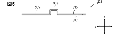
- the series bus bar 331 has two terminal conductive portions 335 and one connecting conductive portion 336.
- the two terminal conductive portions 335 are arranged so as to be separated from each other in the y direction. These two terminal conductive portions 335 are connected via the connecting conductive portion 336.
- the terminal conductive portion 335 has a thin flat plate shape in the z direction.
- the thickness of the terminal conductive portion 335 is determined so that during laser welding of the terminal conductive portion 335 and the electrode terminal of the battery cell 210, it is possible to avoid raising the temperature to such an extent that the performance of the battery cell 210 is changed by the laser. There is.
- the connecting conductive part 336 integrally connects the two terminal conductive parts 335.
- the connecting conductive portion 336 extends from one of the two terminal conductive portions 335 in a z-direction manner, then folds back and extends in the z-direction toward the other of the two terminal conductive portions 335. Due to such a configuration, the connecting conductive portion 336 has a property of being easily deformed in the y direction in which the two terminal conductive portions 335 are lined up.
- the two terminal conductive portions 335 are laser welded to the negative electrode terminal 211 and the positive electrode terminal 212 having different positions in the y direction. By this laser welding, two battery cells 210 arranged next to each other in the y direction are electrically connected in series.
- a conductive extension portion 337 is connected to one of the two terminal conductive portions 335.
- the conductive extension portion 337 extends in the x direction from the terminal conductive portion 335.
- a voltage detection hole 337a for electrically connecting to the voltage sensor 350b, which will be described later, is formed in the conductive extension portion 337.
- the voltage detection hole 337a penetrates the conductive extension portion 337 in the z direction.
- the negative electrode bus bar 333 has one terminal conductive portion 335 and an output conductive portion 338.
- the positive electrode bus bar 334 also has one terminal conductive section 335 and an output conductive section 338 in the same manner as the negative electrode bus bar 333.
- the terminal conductive portion 335 and the output conductive portion 338 are integrally connected.
- the above-mentioned conductive extension portion 337 is integrally connected to the terminal conductive portion 335 of these two types of bus bars.
- the terminal conductive portion 335 of the negative electrode bus bar 333 is laser welded to the negative electrode terminal 211 of the battery cell 210 having the lowest potential.
- the output conductive portion 338 is arranged to face the terminal block 234 of the negative electrode output terminal 232 in the z direction.
- the positive electrode terminal 212 of the battery cell 210 having the maximum potential of the terminal conductive portion 335 of the positive electrode bus bar 334 is laser welded.
- the output conductive portion 338 is arranged to face the terminal block 234 of the positive electrode output terminal 233 in the z direction.
- An output hole 338a penetrating in the z direction is formed in each of the output conductive portions 338 of the negative electrode bus bar 333 and the positive electrode bus bar 334.
- the shaft portion of the external connection terminal 235 is passed through the output hole 338a.
- the terminal of the wire harness is passed through the shaft portion of this external connection terminal 235. Then, a nut is fastened to the shaft portion of the external connection terminal 235. As a result, the output conductive portion 338 and the terminal of the wire harness are sandwiched between the terminal block 234 and the nut. The output conductive portion 338 and the terminal of the wire harness come into contact with each other, and both are electrically connected.
- the wire harness that is electrically connected to the output conductive portion 338 is electrically connected to the power conversion device.
- the DC power of the battery pack 100 is supplied to this power conversion device.
- the power conversion device converts the supplied DC power into AC power.
- This AC power is supplied to the motor as a power source for traveling the electric vehicle. This causes the motor to run.
- the AC power generated by the power generation by the motor is converted into DC power by the power conversion device.
- This DC power is supplied to the battery pack 100. As a result, the battery pack 100 is charged.
- the power conversion device may have a converter function for converting the voltage level of the input power.
- the sensor 350 detects the physical quantity of the battery cell 210. As shown in FIGS. 2 and 3, the sensor 350 includes a temperature sensor 350a and a voltage sensor 350b.
- the temperature sensor 350a detects the temperature of a representative battery cell 210 to be detected among the plurality of battery cells 210.
- the voltage sensor 350b detects the output voltage of each of the plurality of battery cells 210 connected in series.
- the temperature sensor 350a has a thermistor and a temperature detection wiring that electrically connects the thermistor and the monitoring board 390.
- the thermistor is contact-arranged on the first end surface 210a of the representative battery cell 210.
- a temperature detection wiring extends from this thermistor toward the wiring connector 372 described later.
- the voltage sensor 350b has a first detection terminal 351 and a detection screw 352, a fuse 353, a second detection terminal 354, and a voltage detection wiring 355.
- the first detection terminal 351 is connected to the conductive extension portion 337 by the detection screw 352. Further, the first detection terminal 351 is connected to the second detection terminal 354 via a fuse 353.
- a voltage detection wiring 355 is connected to the second detection terminal 354. The voltage detection wiring 355 extends from the second detection terminal 354 toward the wiring connector 372.
- the voltage sensor 350b will be described in detail later.
- the fuse 353 corresponds to an electronic element.
- the wiring case 370 is made of an insulating resin material.
- the wiring case 370 has a frame shape that opens in the z direction.
- the wiring case 370 is fixed to the bus bar case 310 by a snap fit or the like.
- the wiring case 370 corresponds to the resin case.
- the wiring case 370 has two wiring storage portions 371 extending in the y direction and a wiring connector 372 provided with wiring for the sensor 350. Further, the wiring case 370 has two support portions extending in the x direction and an auxiliary storage portion.
- the wiring case 370 has a frame shape.
- the wiring connector 372 is provided on one of the two support portions.
- the auxiliary compartment extends from the other of the two supports towards the wiring connector 372.
- the voltage detection wiring 355 is stored inside the wiring storage unit 371.
- the temperature detection wiring is stored inside the auxiliary storage unit.
- the tips of the voltage detection wiring 355 and the temperature detection wiring that have passed through the inside (wiring passage) of these storage portions are provided in the wiring connector 372.
- the wiring storage portion 371 has a base portion 373 extending in the y direction and a lid portion 374. By combining these, a wiring passage is formed between the two. A part of the wiring passage is enlarged and shown in FIG.
- the base portion 373 is formed with a first frame portion 375 aligned with the series bus bar 331 in the x direction.
- the first frame portion 375 extends in an annular shape around the z direction and opens in the z direction.
- the conductive extension portion 337 and the first detection terminal 351 are connected by a detection screw 352 on the base portion 373 on both sides of the first frame portion 375 on both sides in the y direction.
- the first detection terminal 351 and the second detection terminal 354 are connected to each other via a fuse 353 in the hollow of the first frame portion 375.
- the second detection terminal 354 and the voltage detection wiring 355 are connected on the base portion 373 on the other side of the first frame portion 375 on both sides in the y direction.
- the wiring case 370 has a second frame portion 376 that is nested in the hollow of the first frame portion 375.
- the second frame portion 376 is inserted into the hollow of the first frame portion 375 with the first detection terminal 351 and the second detection terminal 354 and the fuse 353 provided in the hollow.
- the second frame portion 376 is fixed to the first frame portion 375.
- a fuse 353 is provided in the hollow of the second frame portion 376 in a state where the second frame portion 376 is fixed to the first frame portion 375.
- the first detection terminal 351 and the second detection terminal 354 each come into contact with the second frame portion 376 while facing each other in the z direction. By this contact, the positions of the first detection terminal 351 and the second detection terminal 354 in the z direction are defined.
- the monitoring board 390 has a circuit board 391, a first connector 392, and a second connector 393.
- the circuit board 391 has a printed circuit board, a high voltage circuit section, a low voltage circuit section, and an isolated circuit section.
- the first connector 392, the second connector 393, the high voltage circuit section, the low voltage circuit section, and the insulation circuit section are each mounted on the printed circuit board.
- the wiring connector 372 is electrically connected to the first connector 392 via a wire harness.
- An external battery ECU is electrically connected to the second connector 393 via a wire harness.
- the high voltage circuit unit is electrically connected to the first connector 392.
- the low voltage circuit section is electrically connected to the second connector 393.
- the isolated circuit section functions to transmit and receive signals to and from each other while electrically insulating the high voltage circuit section and the low voltage circuit section.
- the high voltage circuit section has a monitoring IC chip.
- the monitoring IC chip converts the analog signal as a detection result input from the sensor 350 into a digital signal.
- the isolated circuit section outputs the digital signal input from the high voltage circuit section to the low voltage circuit section.
- the low voltage circuit section has a microcomputer for communication. By communicating with the battery ECU, the microcomputer outputs a digital signal as a detection result input from the insulation circuit unit to the battery ECU.
- the battery ECU determines the equalization of the SOCs of each of the plurality of battery cells 210 based on the input voltage and temperature detection results. Then, the battery ECU outputs an instruction for equalization processing based on the judgment to the monitoring board 390. This instruction signal is input to the monitoring IC chip of the high voltage circuit section via the low voltage circuit section and the insulation circuit section.
- the monitoring IC chip includes a switch for selectively charging and discharging the battery cell 210 by connecting at least two negative electrode terminals 211 of the plurality of battery cells 210 and the positive electrode terminals 212 to each other. ..
- the monitoring IC chip controls the opening and closing of the switch according to the instruction input from the battery ECU.
- the plurality of battery cells 210 are electrically connected.
- the battery cell 210 having a relatively high SOC is discharged, and the battery cell 210 having a relatively low SOC is charged.
- the SOCs of the plurality of battery cells 210 are equalized.
- SOC is an abbreviation for state of charge.
- the cover 400 has a top plate 410 and an edge wall 420.
- the top plate 410 and the edge wall 420 are integrally connected.
- the top plate 410 and the edge wall 420 are each manufactured of an insulating resin material.
- the top plate 410 has a flat shape with a thin thickness in the z direction.
- the top plate 410 has an inner top surface 410b which is arranged apart from each other in the z direction and an outer top surface 410b on the back side thereof.
- the edge wall 420 stands up in the z direction from the inner surface.
- the edge wall 420 extends along the edge of the inner top surface and forms an annular shape in the circumferential direction around the z direction.
- the cover 400 has a shorter length in the x direction than the battery case 220. Therefore, as shown in FIG. 1, with the cover 400 assembled to the bus bar case 310, the two wiring storage portions 371 provided in the wiring case 370 are located outside the cover 400. The cover 400 is located between the two wiring compartments 371 in the x direction.
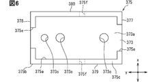
- the first frame portion 375 is integrally connected to the base portion 373 of the wiring case 370 that constitutes a part of the wiring passage. As shown in FIGS. 6 and 7, the first frame portion 375 has the first wall portion 377 and the second wall portion 378 arranged apart from each other in the y direction, and the third wall portion 379 and the third wall portion 379 arranged apart from each other in the x direction. It has 4 wall portions 380.
- the first wall portion 377, the third wall portion 379, the second wall portion 378, and the fourth wall portion 380 are connected in this order in the circumferential direction around the z direction.
- the hollow of the first frame portion 375 is partitioned by the first inner surface 375a of these four wall portions.
- These four wall portions have a first upper surface 375c and a first lower surface 375d arranged apart from each other in the z direction.
- An opening formed on the first upper surface 375c side of these four wall portions communicates with the external space.
- the opening formed on the first lower surface 375d side of these four wall portions is closed by the base portion 373.
- FIGS. 6 and 7 in addition to the first frame portion 375, a portion of the base portion 373 that closes the opening on the first lower surface 375d side of the first frame portion 375 is shown.
- a plurality of through holes 373c opened in the mounting surface 373a and its back surface 373b are formed in a portion of the base portion 373 that closes the opening on the first lower surface 375d side of the first frame portion 375. ing. The tip side of each of the lead terminal 353b and the specified portion 376h, which will be described later, is passed through these plurality of through holes 373c.
- Each of the first wall portion 377 and the second wall portion 378 is formed with a first slit 375e notched from the first upper surface portion 375c toward the first lower surface portion 375d.
- the first slit 375e of the present embodiment cuts out a part of each of the first wall portion 377 and the second wall portion 378 so as to divide each of the first wall portion 377 and the second wall portion 378 into two. There is.
- the base portion 373 extends in the y direction. Therefore, the first wall portion 377 extending in the x direction of the first frame portion 375 and the second wall portion 378 intersect with each other in the extension direction of the base portion 373.
- the first slit 375e formed in the first wall portion 377 has a hollow of the first frame portion 375 and a space on one side of the base portion 373 on both sides of the first frame portion 375 in the y direction in the y direction. Communicate.
- the first slit 375e formed in the second wall portion 378 communicates the hollow of the first frame portion 375 with the space on the base portion 373 on the other side of the first frame portion 375 on both sides in the y direction in the y direction. doing.
- a first detection terminal 351 is provided.
- a second detection terminal 354 is provided in each of the hollow second wall portion 378 side of the first frame portion 375, the first slit 375e of the second wall portion 378, and the space on the base portion 373 communicating with the first slit 375e.
- Each of the third wall portion 379 and the fourth wall portion 380 is formed with a fitting hole 375f that opens into the first inner surface 375a and the first outer surface 375b on the back side thereof.
- one fitting hole 375f is formed in each of the third wall portion 379 and the fourth wall portion 380.
- the fitting holes 375f formed in each wall portion are arranged so as to be separated in the x direction.
- a protrusion 376f which will be described later, is inserted into the fitting hole 375f.
- the second frame portion 376 has the fifth wall portion 381 and the sixth wall portion 382 arranged apart from each other in the y direction, and the seventh wall portion 383 and the seventh wall portion 383 arranged apart from each other in the x direction. It has 8 wall portions 384.
- the fifth wall portion 381, the seventh wall portion 383, the sixth wall portion 382, and the eighth wall portion 384 are connected in this order in the circumferential direction around the z direction.
- the hollow of the second frame portion 376 is partitioned by the second inner surface 376a of these four wall portions.
- These four wall portions have a second upper surface 376c and a second lower surface 376d arranged apart from each other in the z direction. An opening formed by each of the second upper surface 376c side and the second lower surface 376d side of these four wall portions communicates with the external space.
- the second frame portion 376 is housed in the hollow of the first frame portion 375. Therefore, the length of the second frame portion 376 in the y direction is shorter than the length of the hollow first frame portion 375 in the y direction. The length of the second frame portion 376 in the x direction is shorter than the length of the hollow of the first frame portion 375 in the x direction.
- the length of the second frame portion 376 in the y direction is the length between the second outer surface 376b on the back side of the second inner surface 376a of each of the fifth wall portion 381 and the sixth wall portion 382.
- the hollow length of the first frame portion 375 in the y direction is the length between the first inner surface 375a of each of the first wall portion 377 and the second wall portion 378.
- the length of the second frame portion 376 in the x direction is the length between the second outer surface 376b of each of the seventh wall portion 383 and the eighth wall portion 384.
- the hollow x-direction length of the first frame portion 375 is the length between the first inner surface 375a of each of the third wall portion 379 and the fourth wall portion 380.
- a protrusion 376f protruding in the x direction is formed on the second outer surface 376b of each of the 7th wall portion 383 and the 8th wall portion 384.
- one protrusion 376f is formed on each of the seventh wall portion 383 and the eighth wall portion 384.
- the extension directions of the protrusions 376f formed on each wall are opposite to each other in the x direction.
- the sum of the lengths of the protrusions 376f and the second frame portion 376 in the x-direction is longer than the hollow length of the first frame portion 375 in the x-direction.
- the length between the second upper surface 376c and the second lower surface 376d of the four wall portions provided by the second frame portion 376 is the first upper surface 375c and the first lower surface 375d of the four wall portions provided by the first frame portion 375. It is shorter than the length between.
- Two second slits 376e notched from the second upper surface 376c toward the second lower surface 376d are formed on each of the seventh wall portion 383 and the eighth wall portion 384.
- a protrusion 376f is formed between the formation regions of the two second slits 376e in each wall portion. With this configuration, the formed portion of the protrusion 376f of each wall portion tends to bend in the x direction.
- the tip end side of the protrusion 376f comes into contact with the first inner surface 375a of each of the third wall portion 379 and the fourth wall portion 380.
- the forming portions of the protrusions 376f of the seventh wall portion 383 and the eighth wall portion 384 are elastically deformed in such a manner that the separation distance in the x direction from each other is shortened.
- the protrusion 376f reaches the fitting hole 375f of each of the third wall portion 379 and the fourth wall portion 380, the seventh wall portion 383 and the eighth wall portion 384 are each restored to their original shapes, and the protrusion 376f is fitted with the fitting hole. It is fitted in 375f.
- the second frame portion 376 is fixed to the first frame portion 375.
- the second upper surface portion 376c of the second frame portion 376 and the first upper surface portion 375c of the first frame portion 375 are respectively in the z direction.
- the height position of is the same.
- the length of the second frame portion 376 is shorter in the z direction than that of the first frame portion 375. Therefore, the second lower surface 376d of the second frame portion 376 is located in the hollow of the first frame portion 375.
- a gap is formed between the second lower surface 376d of the second frame portion 376 and the first lower surface 375d of the first frame portion 375.
- a gap is formed between the second lower surface 376d of the second frame portion 376 and the mounting surface 373a of the base portion 373. A part of each of the first detection terminal 351 and the second detection terminal 354 is provided in this gap.
- a support base 376 g is connected to the second inner surface 376a of the sixth wall portion 382.
- a pillar-shaped defining portion 376h extending in the z direction is connected to the support base 376g.
- the regulation portion 376h extends from the support base 376g toward the second lower surface 376d side in the z direction.
- the tip of the support base 376 g projects out of the hollow of the second frame portion 376. With the second frame portion 376 fixed to the first frame portion 375, the tip of the support base 376g projects out of the hollow of the first frame portion 375 through the through hole 373c.
- the extension frame portion 376i is connected to the second outer surface 376b of the sixth wall portion 382.
- the extension frame portion 376i has a frame shape that opens in the z direction together with the second frame portion 376.
- the extension frame portion 376i has an upper surface and a lower surface arranged apart from each other in the z direction.
- the lower surface extends in a plane orthogonal to the z direction.
- the upper surface is curved so as to be convex toward the lower surface in the z direction.
- the thickness in the z direction between the upper surface and the lower surface of the extension frame portion 376i becomes thinner as it is separated from the sixth wall portion 382 in the y direction. As a result, the portion of the extension frame portion 376i separated from the sixth wall portion 382 is likely to bend in the z direction.
- the portion of the extension frame portion 376i that easily bends in the z direction comes into contact with the portion of the voltage detection wiring 355 connected to the second detection terminal 354.
- the second detection terminal 354 side of the voltage detection wiring 355 is pressed against the base portion 373.
- the second detection terminal 354 side of the voltage detection wiring 355 is sandwiched between the extension frame portion 376i and the base portion 373.
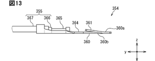
- the first detection terminal 351 and the second detection terminal 354 have a thin shape. These detection terminals are made by pressing a thin metal plate. These detection terminals have a terminal connection portion 360 and a spring portion 361 as common components.
- the terminal connection portion 360 has a thin flat plate shape in the z direction.
- the terminal connection portion 360 has an upper surface 360a and a lower surface 360b arranged apart from each other in the z direction.
- the terminal connection portion 360 is formed with a connection hole 360c that opens in the upper surface 360a and the lower surface 360b.
- terminal connection portions 360 for each of the first detection terminal 351 and the second detection terminal 354 are provided in the hollow of the first frame portion 375. Then, the lead terminal 353b of the fuse 353 is inserted into the connection hole 360c of the terminal connection portion 360 of each of these two detection terminals. The tip of the lead terminal 353b projects out of the hollow of the first frame portion 375 through the through hole 373c. The terminal connection portion 360 in which the connection hole 360c is formed and the lead terminal 353b are connected by the solder 353c. As a result, the terminal connection portions 360 of the two detection terminals are electrically and mechanically connected to each other via the fuse 353 and the solder 353c. The solder 353c corresponds to the conductive adhesive.
- the spring portion 361 is cantilevered by the terminal connection portion 360 and has a shape that easily bends in the z direction.
- One end of the spring portion 361 is integrally connected to the terminal connection portion 360.
- the spring portion 361 extends in the z direction from the lower surface 360b of the terminal connecting portion 360 toward the upper surface 360a and also extends in the y direction.
- the other end of the spring portion 361 is not opposed to and separated from the upper surface 360a of the terminal connecting portion 360 in the z direction.
- the spring portion 361 tends to bend in the z direction with one end connected to the terminal connecting portion 360 as a fulcrum.
- the spring portion 361 is provided in the hollow of the first frame portion 375 together with the terminal connection portion 360.
- a second frame portion 376 is also provided in the hollow of the first frame portion 375. When the second frame portion 376 is inserted into the hollow of the first frame portion 375, the other ends of the spring portions 361 of the first detection terminal 351 and the second detection terminal 354 are attached to the second lower surface 376d of the second frame portion 376. Contact. The second frame portion 376 corresponds to the pressing portion.
- the spring portion 361 elastically deforms from the upper surface 360a to the lower surface 360b in the z direction. As a result, an elastic force acting on the second frame portion 376 from the spring portion 361 is generated in the spring portion 361. The reaction force of this elastic force acts from the second frame portion 376 to the spring portion 361. By this reaction force, one end side connected to the terminal connection portion 360 of the spring portion 361 is pressed against the base portion 373.
- the magnitude of the elastic force generated in the spring portion 361 is determined.
- the spring portion 361 is provided in the hollow of the first frame portion 375 in a state of being contracted in the z direction.
- the elastic force generated by the spring portion 361 is applied to the second frame portion 376, and the terminal connection portion 360 is pressed against the base portion 373 by the reaction force of the elastic force.
- the terminal connection portions 360 of the first detection terminal 351 and the second detection terminal 354 are fixed to the wiring case 370.
- two spring portions 361 are integrally connected to the terminal connection portion 360.
- One end side of these two spring portions 361 is arranged so as to be separated from each other in the x direction. Therefore, the contact points of the other ends of these two spring portions 361 with the second frame portion 376 are also arranged apart from each other in the x direction.
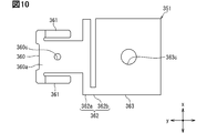
- the first detection terminal 351 has a first relay portion 362 and a bolt connection portion 363 in addition to the terminal connection portion 360 and the spring portion 361.
- the first relay portion 362 has a longitudinal portion 362a and a short portion 362b that are integrally connected to each other.
- the longitudinal portion 362a is connected to the terminal connecting portion 360.
- the short end portion 362b is connected to the bolt connection portion 363.
- the length of the longitudinal portion 362a is longer in the x direction than that of the terminal connection portion 360.
- the short portion 362b has a shorter length in the x direction than the terminal connection portion 360.
- the bolt connection portion 363 has a longer length in each of the x direction and the y direction than the terminal connection portion 360.
- the bolt connection portion 363 has a rectangular shape in a plane orthogonal to the z direction.
- a bolt hole 363c penetrating in the z direction is formed in the bolt connection portion 363.
- the bolt connection portion 363 is laminated with the conductive extension portion 337 in the z direction.
- the bolt hole 363c and the voltage detection hole 337a communicate with each other in the z direction.
- the bolt connection portion 363 corresponds to the fixing portion.
- the bolt hole 363c corresponds to the fixing hole.
- an arrangement hole 373d that opens in the z direction is formed in the base portion 373.
- a conductive extension portion 337 is provided in the arrangement hole 373d.
- the detection screw 352 has a shaft portion in which a thread groove is formed and a head portion connected to an end portion of the shaft portion.
- the tip end side of the shaft portion of the detection screw 352 is inserted into the voltage detection hole 337a from the bolt hole 363c.
- a nut 352a is fastened to the tip end side of the shaft portion of the detection screw 352.
- a bolt connection portion 363 and a conductive extension portion 337 are sandwiched between the head of the detection screw 352 and the nut 352a.
- the bolt connection portion 363 and the conductive extension portion 337 come into contact with each other, and both are electrically connected.
- the bolt connection portion 363 is pressed against the base portion 373 by this fastening.
- the bolt connection portion 363 and the conductive extension portion 337 are fixed to the base portion 373, respectively.
- the terminal connection portion 360 connected to the bolt connection portion 363 via the first relay portion 362 is fixed to the base portion 373.
- the conductive extension portion 337 is provided in the arrangement hole 373d formed in the base portion 373.
- the conductive extension portion 337 is provided in the arrangement hole 373d
- a configuration in which the nut 352a is provided in the arrangement hole 373d can also be adopted.
- a washer may be passed through the shaft portion of the detection screw 352 in order to stabilize the fixed state of each of the bolt connection portion 363 and the conductive extension portion 337 with respect to the base portion 373.
- the short portion 362b having a short length in the x direction is connected to the bolt connection portion 363. Therefore, even if the bolt connection portion 363 is twisted by fastening the nut 352a to the shaft portion of the detection screw 352 described above, the twist is suppressed from being transmitted to the longitudinal portion 362a.
- the length of the longitudinal portion 362a is long in the x direction. Therefore, even if the longitudinal portion 362a is twisted by fastening the nut 352a to the shaft portion of the detection screw 352, the arrangement position of the first detection terminal 351 with respect to the base portion 373 due to the contact of the longitudinal portion 362a with the base portion 373. Is suppressed from fluctuating. The action of stress on the solder 353c connecting the first detection terminal 351 and the fuse 353 is suppressed. It is possible to suppress the occurrence of electrical connection failure between the first detection terminal 351 and the lead terminal 353b.
- connection point of the terminal connection portion 360 at one end of the two spring portions 361 described above is indicated by a cross in FIG. These two connecting points are pressed against the base portion 373 by the elastic force of the spring portion 361.
- a line passing through these connecting points and along the z direction is shown as a alternate long and short dash line.
- the bolt hole 363c of the bolt connection portion 363 is a fixing point with the base portion 373.
- the connection hole 360c of the terminal connection portion 360 is located in the triangle connecting the bolt hole 363c and one end of the two spring portions 361.
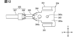
- the second detection terminal 354 has a second relay portion 364 and a caulking portion 365 in addition to the terminal connection portion 360 and the spring portion 361.
- the second relay unit 364 integrally connects the terminal connection unit 360 and the caulking unit 365.
- a defined hole 364a penetrating in the z direction is formed in the second relay portion 364.
- the regulation portion 376h of the second frame portion 376 is inserted into the regulation hole 364a. This defines the position of the second relay unit 364 in the direction orthogonal to the z direction.
- the terminal connection portion is in a triangle connecting the fixing hole 364a of the regulation portion 376h of the second relay portion 364 and the connection point of the terminal connection portion 360 at one end of the two spring portions 361 indicated by x in FIG.
- the connection hole 360c of 360 is located.
- the caulking portion 365 has a tubular shape extending in the y direction.
- the second relay portion 364 is integrally connected to one end of the caulking portion 365.
- the voltage detection wiring 355 is inserted into the opening of the caulking portion 365 on the other end side.
- the voltage detection wiring 355 is an insulated wire in which the conducting wire 366 is covered with an insulating coating 367. On the end side of the voltage detection wiring 355, the end of the lead wire 366 is exposed from the insulating coating 367. Each of the exposed portion of the conducting wire 366 from the insulating coating 367 and the end side of the insulating coating 367 located near the exposed portion are provided in the hollow of the caulked portion 365.
- the caulked portion 365 By heat caulking, the caulked portion 365 forming a tubular shape is deformed so that its own hollow is shrunk. Due to this deformation, the end sides of the conducting wire 366 and the insulating coating 367 are fixed to the caulked portion 365. The caulked portion 365 is in direct contact with the conducting wire 366. As a result, the voltage detection wiring 355 and the second detection terminal 354 are electrically and mechanically connected.
- the extension frame portion 376i is connected to the second outer surface 376b of the sixth wall portion 382.
- the portion of the extension frame portion 376i that easily bends in the z direction is in contact with the fixed end side of the caulking portion 365 of the voltage detection wiring 355.
- the voltage detection wiring 355 is pressed against the base portion 373.
- the terminal connection portion 360 is fixed to the base portion 373 together with the second relay portion 364 to which the voltage detection wiring 355 is connected.
- connection hole 360c of the terminal connection portion 360 is in the triangle connecting the pressing point pressed against the base portion 373 of the voltage detection wiring 355 and the connection point of the terminal connection portion 360 at one end of the two spring portions 361 indicated by x. Is located.
- the fuse 353 connecting the two terminal connecting portions 360 to each other has one main body portion 353a and two lead terminals 353b.
- the main body portion 353a has a pillar shape extending in the y direction.
- the two lead terminals 353b extend from each of the two end faces of the main body portion 353a.
- the lead terminal 353b extends in the y direction from the end surface of the main body portion 353a and then extends in the z direction. As shown in FIG. 17, the tip of the lead terminal 353b is inserted from the opening on the upper surface 360a side of the connection hole 360c toward the inside thereof. The tip of the lead terminal 353b protrudes out of the connection hole 360c and the through hole 373c. The tip of the lead terminal 353b and the lower surface 360b side of the terminal connection portion 360 are electrically and mechanically connected via the solder 353c.
- a part of the lead terminal 353b is curved so as to be convex in the y direction away from the main body portion 353a. Therefore, as shown in FIG. 17, when the tip end side of the lead terminal 353b is inserted into the connection hole 360c, the curved portion of the lead terminal 353b comes into contact with the edge portion of the connection hole 360c on the upper surface 360a side and the upper surface 360a around the lead terminal 353b. Such contact defines the position of the fuse 353 in the z direction with respect to the terminal connection 360. Further, the bending portion of the lead terminal 353b suppresses the vibration of the main body portion 353a.
- each of the first detection terminal 351 and the second detection terminal 354 has a terminal connection portion 360 and a spring portion 361 as common components.
- the lead terminal 353b of the fuse 353 is inserted into the connection hole 360c formed in the terminal connection portion 360.
- the terminal connection portion 360 and the lead terminal 353b are connected by a solder 353c.
- the spring portion 361 extends in the z direction from the lower surface 360b of the terminal connecting portion 360 toward the upper surface 360a and also extends in the y direction.
- the second frame portion 376 comes into contact with the other end of the spring portion 361.
- the spring portion 361 contracts from the upper surface 360a to the lower surface 360b in the z direction, and elastic force is applied from the spring portion 361 to the second frame portion 376.
- the spring portion 361 is provided in the hollow of the first frame portion 375 in a state of being contracted in the z direction.
- the first detection terminal 351 and the second detection terminal 354 are fixed to the base portion 373 by the elastic force of the spring portion 361 and the reaction force acting on the elastic force from the second frame portion 376 toward the spring portion 361. NS.
- the spring portion 361 elastically deforms in the z direction in response to the vibration. As a result, the vibration of the connected terminal connection portion 360 of the spring portion 361 is suppressed. The action of stress on the solder 353c connecting the terminal connection portion 360 and the lead terminal 353b is suppressed. It is possible to suppress the occurrence of electrical connection failure between the terminal connection portion 360 and the lead terminal 353b.
- a configuration in which the terminal connection portion 360 is sandwiched between the second frame portion 376 fixed to the first frame portion 375 and the base portion 373 can be considered.
- the protrusion 376f of the second frame portion 376 is fitted into the fitting hole 375f of the first frame portion 375, so that the second frame portion 376 is fixed to the first frame portion 375.
- the fixed position of the second frame portion 376 with respect to the first frame portion 375 has an error due to the manufacturing error of each of the first frame portion 375 and the second frame portion 376.
- the spring portion 361 integrally connected to the terminal connecting portion 360 as described above is elastically deformed by being pressed by the second frame portion 376. Due to this configuration, even if the fixed position of the second frame portion 376 with respect to the first frame portion 375 fluctuates, between the spring portion 361 and the second frame portion 376, and between the terminal connection portion 360 and the base portion 373. The formation of gaps between them is suppressed. Therefore, it is suppressed that the fixed state of the terminal connection portion 360 with respect to the base portion 373 becomes extremely unstable. As a result, the action of stress on the solder 353c connecting the terminal connection portion 360 and the lead terminal 353b is suppressed.
- one end of two spring portions 361 is connected to the terminal connection portion 360.
- the connection point of the terminal connection portion 360 at one end of these two spring portions 361 is the fixing point of the base portion 373.
- the bolt hole 363c of the bolt connection portion 363 is a fixing point with the base portion 373.
- the connection hole 360c of the terminal connection portion 360 is located in a triangle connecting the bolt hole 363c and the connection point of the terminal connection portion 360 at one end of the two spring portions 361.
- the defined hole 364a of the second relay portion 364 and the portion pressed against the base portion 373 by the extension frame portion 376i in the voltage detection wiring 355 are fixed points with the base portion 373. ..
- the connection hole 360c of the terminal connection portion 360 is located in a triangle connecting one of these two fixing points and the connection point of the terminal connection portion 360 at one end of the two spring portions 361.
- connection hole 360c corresponding to the connection portion with the lead terminal 353b in the terminal connection portion 360 in the triangle connecting the three fixed points. Is located. Therefore, the position of the connection hole 360c is less likely to change relative to the base portion 373 as compared with the configuration in which the connection hole 360c is located outside the triangle.
- connection hole 360c and the base portion 373 suppresses the action of stress on the solder 353c that connects the terminal connection portion 360 in which the connection hole 360c is formed and the lead terminal 353b. This suppresses the occurrence of electrical connection failure between the terminal connection portion 360 and the lead terminal 353b.
- the first detection terminal 351 and the second detection terminal 354 are fixed to the connected base portion 373 of the first frame portion 375 via the second frame portion 376, respectively.
- the first frame portion 375 is connected to the base portion 373. Therefore, even if the first wall portion 377 and the second wall portion 378 are each divided into two by the first slit 375e, these two divided wall portions are connected via the base portion 373. Although only the first frame portion 375 is shown in FIG. 18, the boundary between the first frame portion 375 and the base portion 373 is shown by a alternate long and short dash line.
- the lead terminal 353b is connected to each of the first detection terminal 351 and the second detection terminal 354 by the solder 353c.
- the conductive adhesive for connecting each of the first detection terminal 351 and the second detection terminal 354 and the lead terminal 353b is not limited to the above example.
- the conductive adhesive for example, silver paste or the like can be adopted.
- each of the first detection terminal 351 and the second detection terminal 354 has two spring portions 361.
- the number of spring portions 361 possessed by each of the first detection terminal 351 and the second detection terminal 354 is not limited to two, and a single number or three or more can be adopted.
- a polygon having four or more points is formed by connecting the connection point of the terminal connection portion 360 at one end of the three or more spring portions 361 and the bolt hole 363c. Will be done.
- the connection point of the terminal connection portion 360 at one end of the three or more spring portions 361 and the fixing point of the base portion 373 of the voltage detection wiring 355 are connected.
- a polygon with four or more points is formed. It is also possible to adopt a configuration in which the connection hole 360c of the terminal connection portion 360 is located in this polygon.
- the battery pack 100 has one battery stack in which a plurality of battery cells 210 are arranged in the y direction.
- the battery pack 100 may have two or more battery stacks.
- the number of battery cells 210 included in each of the two or more battery stacks may be the same or different.
Landscapes
- Chemical & Material Sciences (AREA)
- Chemical Kinetics & Catalysis (AREA)
- Electrochemistry (AREA)
- General Chemical & Material Sciences (AREA)
- Battery Mounting, Suspending (AREA)
- Connections By Means Of Piercing Elements, Nuts, Or Screws (AREA)
- Details Of Connecting Devices For Male And Female Coupling (AREA)
- Connection Of Batteries Or Terminals (AREA)
Abstract
In the present invention, a first detection terminal (351) and a second detection terminal (354) are provided to a wiring case. Said detection terminals each have a terminal connection part (360) to which a lead terminal (353b) is connected by solder (353c), and a spring part (361) which is integrally linked to the terminal connection part and generates elastic force for fixing the terminal connection part to the wiring case.
Description
この出願は、2020年5月21日に日本に出願された特許出願第2020-089082号を基礎としており、基礎の出願の内容を、全体的に、参照により援用している。
This application is based on Patent Application No. 2020-089082 filed in Japan on May 21, 2020, and the contents of the basic application are incorporated by reference as a whole.
本明細書に記載の開示は、電子素子に接続される接続端子、および、それを含む端子モジュールに関するものである。
The disclosure described in this specification relates to a connection terminal connected to an electronic device and a terminal module including the connection terminal.
特許文献1にはバッテリ接続プレートが示されている。バッテリ接続プレートは、複数のバッテリに装着されるプレート本体と、プレート本体に装備されるとともに、バッテリと電子部品とを接続する端子と、を備えている。
Patent Document 1 shows a battery connection plate. The battery connection plate includes a plate body mounted on a plurality of batteries, a terminal mounted on the plate body, and a terminal for connecting the battery and an electronic component.
特許文献1に示されるバッテリ接続プレートの端子には、バッテリに設けられた雄ねじ状の電極が通される挿通孔と、電子部品に突設されたリード端子が挿通されるとともに半田付けされる小孔と、が形成されている。
In the terminal of the battery connection plate shown in Patent Document 1, an insertion hole through which a male screw-shaped electrode provided in the battery is passed and a lead terminal projecting from an electronic component are inserted and soldered. A hole is formed.
係る構成においては、例えば外力の印加などによって端子が振動すると、端子と電子部品のリード端子とを接続する半田に応力が作用する虞がある。係る応力の作用によって端子とリード端子とに電気的な接続不良の生じる虞がある。
In such a configuration, if the terminal vibrates due to, for example, application of an external force, stress may act on the solder connecting the terminal and the lead terminal of the electronic component. The action of such stress may cause an electrical connection failure between the terminal and the lead terminal.
本開示の目的は、リード端子との電気的な接続に不良の生じることの抑制された接続端子、および、それを含む端子モジュールを提供することである。
An object of the present disclosure is to provide a connection terminal in which a defect is suppressed in electrical connection with a lead terminal, and a terminal module including the connection terminal.
本開示の一態様による接続端子は、樹脂ケースに設けられるとともに、電子素子のリード端子が導電性接着剤によって接続される接続端子であって、
リード端子の接続される端子接続部と、
端子接続部に一体的に連結され、端子接続部を樹脂ケースに固定するための弾性力を発生するバネ部と、を有する。 The connection terminal according to one aspect of the present disclosure is a connection terminal provided in the resin case and to which the lead terminal of the electronic element is connected by a conductive adhesive.
The terminal connection part to which the lead terminal is connected and
It has a spring portion that is integrally connected to the terminal connection portion and generates an elastic force for fixing the terminal connection portion to the resin case.
本開示の一態様による端子モジュールは、樹脂ケースと、
樹脂ケースに固定される接続端子と、
接続端子に導電性接着剤によってリード端子の接続される電子素子と、を有する端子モジュールであって、
接続端子は、
リード端子の接続される端子接続部と、
端子接続部に一体的に連結され、端子接続部を樹脂ケースに固定するための弾性力を発生するバネ部と、を有する。 The terminal module according to one aspect of the present disclosure includes a resin case and
The connection terminal fixed to the resin case and
A terminal module having an electronic element to which a lead terminal is connected to a connection terminal by a conductive adhesive.
The connection terminal is
The terminal connection part to which the lead terminal is connected and
It has a spring portion that is integrally connected to the terminal connection portion and generates an elastic force for fixing the terminal connection portion to the resin case.
これによれば、例え外力の印加などによって樹脂ケースが振動したとしても、その振動によって端子接続部が振動することが抑制される。端子接続部の振動によって端子接続部とリード端子とを接続する導電性接着剤に応力の作用することが抑制される。この結果、端子接続部とリード端子とに電気的な接続不良の生じることが抑制される。
According to this, even if the resin case vibrates due to the application of an external force or the like, the vibration of the terminal connection portion is suppressed. The vibration of the terminal connection portion suppresses the action of stress on the conductive adhesive that connects the terminal connection portion and the lead terminal. As a result, it is possible to prevent an electrical connection failure between the terminal connection portion and the lead terminal.
なお、上記の括弧内の参照番号は、後述の実施形態に記載の構成との対応関係を示すものに過ぎず、技術的範囲を何ら制限するものではない。
Note that the reference numbers in parentheses above merely indicate the correspondence with the configurations described in the embodiments described later, and do not limit the technical scope at all.
以下、図面を参照しながら本開示を実施するための複数の形態を説明する。各形態において先行する形態で説明した事項に対応する部分には同一の参照符号を付して重複する説明を省略する場合がある。各形態において構成の一部のみを説明している場合は、構成の他の部分については先行して説明した他の形態を適用することができる。
Hereinafter, a plurality of forms for carrying out the present disclosure will be described with reference to the drawings. In each form, the same reference numerals may be given to the parts corresponding to the matters described in the preceding forms, and duplicate explanations may be omitted. When only a part of the configuration is described in each form, other forms described above can be applied to the other parts of the configuration.
各実施形態で具体的に組み合わせが可能であることを明示している部分同士の組み合わせが可能である。また、特に組み合わせに支障が生じなければ、組み合わせが可能であることを明示していなくても、実施形態同士、実施形態と変形例、および、変形例同士を部分的に組み合せることも可能である。
It is possible to combine parts that clearly indicate that they can be specifically combined in each embodiment. Further, if there is no particular problem in the combination, it is possible to partially combine the embodiments, the embodiments and the modified examples, and the modified examples with each other, even if it is not clearly stated that the combinations are possible. be.
(第1実施形態)
図1~図17に基づいて接続端子と端子モジュールそれぞれを含む電池パックを説明する。なお図4~図17においては電池パックの各種構成要素を模式的に図示している。本実施形態の電池パック100は電気自動車やプラグインハイブリッド自動車などの電動車両に適用される。 (First Embodiment)
A battery pack including each of the connection terminal and the terminal module will be described with reference to FIGS. 1 to 17. Note that FIGS. 4 to 17 schematically show various components of the battery pack. Thebattery pack 100 of the present embodiment is applied to an electric vehicle such as an electric vehicle or a plug-in hybrid vehicle.
図1~図17に基づいて接続端子と端子モジュールそれぞれを含む電池パックを説明する。なお図4~図17においては電池パックの各種構成要素を模式的に図示している。本実施形態の電池パック100は電気自動車やプラグインハイブリッド自動車などの電動車両に適用される。 (First Embodiment)
A battery pack including each of the connection terminal and the terminal module will be described with reference to FIGS. 1 to 17. Note that FIGS. 4 to 17 schematically show various components of the battery pack. The
以下においては互いに直交の関係にある3方向を、x方向、y方向、z方向と示す。図面においては「方向」の記載を省略して、単に、x、y、zと図示する。
In the following, the three directions that are orthogonal to each other are referred to as the x direction, the y direction, and the z direction. In the drawings, the description of "direction" is omitted, and the description is simply x, y, z.
<車載電池>
図1に電池パック100を示す。電池パック100は車両に複数搭載される。複数の電池パック100がワイヤハーネスなどによって直列接続若しくは並列接続される。これにより車載電源が構成されている。車載電源は車両の電気負荷に電力供給する機能を果たしている。なお1つの電池パック100によって車載電源が構成されてもよい。 <In-vehicle battery>
FIG. 1 shows thebattery pack 100. A plurality of battery packs 100 are mounted on the vehicle. A plurality of battery packs 100 are connected in series or in parallel by a wire harness or the like. This constitutes an in-vehicle power supply. The in-vehicle power supply functions to supply electric power to the electric load of the vehicle. An in-vehicle power supply may be configured by one battery pack 100.
図1に電池パック100を示す。電池パック100は車両に複数搭載される。複数の電池パック100がワイヤハーネスなどによって直列接続若しくは並列接続される。これにより車載電源が構成されている。車載電源は車両の電気負荷に電力供給する機能を果たしている。なお1つの電池パック100によって車載電源が構成されてもよい。 <In-vehicle battery>
FIG. 1 shows the
電池パック100には車両のダクトが連結される。このダクトから電池パック100に、電池パック100の備える複数の電池セル210の温度を調整するための流体が供給される。これにより電池セル210の過度な温度変化が抑制されている。なお電池パック100は車両内を循環する冷却水で温度調整されてもよい。
The vehicle duct is connected to the battery pack 100. A fluid for adjusting the temperature of a plurality of battery cells 210 included in the battery pack 100 is supplied to the battery pack 100 from this duct. As a result, an excessive temperature change of the battery cell 210 is suppressed. The temperature of the battery pack 100 may be adjusted by the cooling water circulating in the vehicle.
車載電源の配置場所としては、例えば車両の前部座席下の空間、後部座席下の空間、および、後部座席とトランクルームとの間の空間などを適宜採用することができる。
As the location of the in-vehicle power supply, for example, the space under the front seat of the vehicle, the space under the rear seat, and the space between the rear seat and the trunk room can be appropriately adopted.
図2に示すように電池パック100は、電池モジュール200、バスバモジュール300、および、カバー400を有する。電池モジュール200は複数の電池セル210と電池ケース220を有する。バスバモジュール300は、バスバケース310、バスバ330、センサ350、配線ケース370、および、監視基板390を有する。
As shown in FIG. 2, the battery pack 100 has a battery module 200, a bus module 300, and a cover 400. The battery module 200 has a plurality of battery cells 210 and a battery case 220. The bus bar module 300 has a bus bar case 310, a bus bar 330, a sensor 350, a wiring case 370, and a monitoring board 390.
複数の電池セル210は電池ケース220に収納される。複数の電池セル210の電池ケース220の開口側がバスバモジュール300によって覆われる。このバスバモジュール300がカバー400によって覆われる。バスバモジュール300に端子モジュールが含まれている。
The plurality of battery cells 210 are housed in the battery case 220. The opening side of the battery case 220 of the plurality of battery cells 210 is covered by the bus module 300. The bus module 300 is covered by the cover 400. The bus module 300 includes a terminal module.
<電池セル>
複数の電池セル210それぞれは二次電池である。電池セル210に採用することのできる二次電池としては、例えば、リチウムイオン二次電池、ニッケル水素二次電池、および、有機ラジカル電池などがある。これら二次電池は化学反応によって起電圧を生成する。 <Battery cell>
Each of the plurality ofbattery cells 210 is a secondary battery. Examples of the secondary battery that can be adopted in the battery cell 210 include a lithium ion secondary battery, a nickel hydrogen secondary battery, and an organic radical battery. These secondary batteries generate an electromotive voltage by a chemical reaction.
複数の電池セル210それぞれは二次電池である。電池セル210に採用することのできる二次電池としては、例えば、リチウムイオン二次電池、ニッケル水素二次電池、および、有機ラジカル電池などがある。これら二次電池は化学反応によって起電圧を生成する。 <Battery cell>
Each of the plurality of
電池セル210は、発電要素と、この発電要素を収納する金属ケースと、を有する。金属ケースはy方向の厚さの薄い平板形状を成している。金属ケースはz方向に並ぶ第1端面210aと第2端面210bを有する。また金属ケースはy方向に並ぶ第1主面と第2主面、および、x方向に並ぶ第1側面と第2側面を有する。これら金属ケースの備える6面のうち、第1主面と第2主面は他の4面と比べて面積が広くなっている。
The battery cell 210 has a power generation element and a metal case for accommodating the power generation element. The metal case has a flat plate shape with a thin thickness in the y direction. The metal case has a first end face 210a and a second end face 210b arranged in the z direction. Further, the metal case has a first main surface and a second main surface arranged in the y direction, and a first side surface and a second side surface arranged in the x direction. Of the six surfaces provided by these metal cases, the first main surface and the second main surface have a larger area than the other four surfaces.
金属ケースの第1端面210aに負極端子211と正極端子212が形成されている。これら負極端子211と正極端子212はx方向で離間して並んでいる。負極端子211は第1側面側に位置している。正極端子212は第2側面側に位置している。
A negative electrode terminal 211 and a positive electrode terminal 212 are formed on the first end surface 210a of the metal case. The negative electrode terminal 211 and the positive electrode terminal 212 are arranged so as to be separated from each other in the x direction. The negative electrode terminal 211 is located on the first side surface side. The positive electrode terminal 212 is located on the second side surface side.
<電池ケース>
電池ケース220は底壁221と側壁222を有する。底壁221と側壁222は一体的に連結されている。底壁221と側壁222それぞれは絶縁性の樹脂材料によって製造されている。 <Battery case>
Thebattery case 220 has a bottom wall 221 and a side wall 222. The bottom wall 221 and the side wall 222 are integrally connected. The bottom wall 221 and the side wall 222 are each made of an insulating resin material.
電池ケース220は底壁221と側壁222を有する。底壁221と側壁222は一体的に連結されている。底壁221と側壁222それぞれは絶縁性の樹脂材料によって製造されている。 <Battery case>
The
底壁221はz方向の厚さの薄い扁平形状を成している。底壁221はz方向に離間して並ぶ内底面221aとその裏側の外底面とを有している。
The bottom wall 221 has a flat shape with a thin thickness in the z direction. The bottom wall 221 has an inner bottom surface 221a arranged apart from each other in the z direction and an outer bottom surface on the back side thereof.
側壁222は内底面221aからz方向に起立している。側壁222は内底面221aの縁に沿って延び、z方向まわりの周方向で環状を成している。
The side wall 222 stands up from the inner bottom surface 221a in the z direction. The side wall 222 extends along the edge of the inner bottom surface 221a and forms an annular shape in the circumferential direction around the z direction.
細分化して説明すると、側壁222はy方向で離間して並ぶ左側壁223と右側壁224、および、x方向で離間して並ぶ前側壁225と後側壁226を有する。z方向まわりの周方向で左側壁223、前側壁225、右側壁224、後側壁226が順に連結されている。これにより側壁222はz方向まわりの周方向で環状を成している。側壁222と底壁221とによって電池ケース220の収納空間が構成されている。
To explain in detail, the side wall 222 has a left side wall 223 and a right side wall 224 arranged apart from each other in the y direction, and a front side wall 225 and a rear side wall 226 arranged apart from each other in the x direction. The left side wall 223, the front side wall 225, the right side wall 224, and the rear side wall 226 are connected in this order in the circumferential direction around the z direction. As a result, the side wall 222 forms an annular shape in the circumferential direction around the z direction. The side wall 222 and the bottom wall 221 form a storage space for the battery case 220.
<隔壁>
電池ケース220は収納空間を複数の個別収納空間に分けるための隔壁227を複数有する。収納空間の底壁221側で複数の隔壁227がy方向に離間して並んでいる。これにより収納空間の底壁221側がy方向に並ぶ複数の個別収納空間に分けられている。 <Septum>
Thebattery case 220 has a plurality of partition walls 227 for dividing the storage space into a plurality of individual storage spaces. A plurality of partition walls 227 are arranged side by side in the y direction on the bottom wall 221 side of the storage space. As a result, the bottom wall 221 side of the storage space is divided into a plurality of individual storage spaces arranged in the y direction.
電池ケース220は収納空間を複数の個別収納空間に分けるための隔壁227を複数有する。収納空間の底壁221側で複数の隔壁227がy方向に離間して並んでいる。これにより収納空間の底壁221側がy方向に並ぶ複数の個別収納空間に分けられている。 <Septum>
The
個別収納空間を構成する電池ケース220の各壁には、その個別収納空間の中央側に向かって突起する複数の微小突起部が形成されている。この微小突起部が変形されるように、複数の個別収納空間それぞれに電池セル210の第2端面210b側が圧入される。これにより、複数の電池セル210それぞれの第2端面210b側が電池ケース220に固定される。左側壁223と右側壁224との間に複数の電池セル210が設けられる。なお、隣接して並ぶ2つの個別収納空間を連通するためのスリットが隔壁227に形成されてもよい。
On each wall of the battery case 220 constituting the individual storage space, a plurality of minute protrusions protruding toward the center side of the individual storage space are formed. The second end surface 210b side of the battery cell 210 is press-fitted into each of the plurality of individual storage spaces so that the minute protrusions are deformed. As a result, the second end surface 210b side of each of the plurality of battery cells 210 is fixed to the battery case 220. A plurality of battery cells 210 are provided between the left side wall 223 and the right side wall 224. A slit may be formed in the partition wall 227 to communicate the two individual storage spaces arranged adjacent to each other.
y方向で隣接して並ぶ任意の2つの電池セル210は、互いに第1主面同士、若しくは、第2主面同士で対向配置される。この対向配置により、y方向で隣接して並ぶ2つの電池セル210のうちの一方の負極端子211と他方の正極端子212とがy方向で並んでいる。
Arbitrary two battery cells 210 arranged adjacent to each other in the y direction are arranged so as to face each other on the first main surface or the second main surface. Due to this facing arrangement, one of the negative electrode terminals 211 and the other positive electrode terminal 212 of the two battery cells 210 adjacent to each other in the y direction are arranged in the y direction.
これらy方向で並ぶ負極端子211と正極端子212とが後述の直列バスバ331によって直列接続される。これにより複数の電池セル210は電気的に直列接続されている。複数の電池セル210がy方向で電位順に並んでいる。y方向に並ぶ複数の電池セル210のうちの両端の一方側に最低電位の電池セル210が位置している。両端の他方側に最高電位の電池セル210が位置している。最低電位の電池セル210が左側壁223側に位置している。最高電位の電池セル210が右側壁224側に位置している。
The negative electrode terminals 211 and the positive electrode terminals 212 arranged in the y direction are connected in series by a series bus bar 331 described later. As a result, the plurality of battery cells 210 are electrically connected in series. A plurality of battery cells 210 are arranged in the order of potential in the y direction. The battery cell 210 having the lowest potential is located on one side of both ends of the plurality of battery cells 210 arranged in the y direction. The highest potential battery cell 210 is located on the other side of both ends. The lowest potential battery cell 210 is located on the left side wall 223 side. The highest potential battery cell 210 is located on the right side wall 224 side.
<出力端子>
左側壁223には最低電位の電池セル210とワイヤハーネスとを電気的に接続するための負極出力端子232が一体的に連結されている。右側壁224には最高電位の電池セル210とワイヤハーネスとを電気的に接続するための正極出力端子233が一体的に連結されている。これら負極出力端子232と正極出力端子233は、電池ケース220の収納空間から離間する態様で側壁222から延びた端子台234と、端子台234に固定された外部接続端子235と、を有する。 <Output terminal>
A negativeelectrode output terminal 232 for electrically connecting the battery cell 210 having the lowest potential and the wire harness is integrally connected to the left side wall 223. A positive electrode output terminal 233 for electrically connecting the battery cell 210 having the highest potential and the wire harness is integrally connected to the right side wall 224. The negative electrode output terminal 232 and the positive electrode output terminal 233 have a terminal block 234 extending from the side wall 222 so as to be separated from the storage space of the battery case 220, and an external connection terminal 235 fixed to the terminal block 234.
左側壁223には最低電位の電池セル210とワイヤハーネスとを電気的に接続するための負極出力端子232が一体的に連結されている。右側壁224には最高電位の電池セル210とワイヤハーネスとを電気的に接続するための正極出力端子233が一体的に連結されている。これら負極出力端子232と正極出力端子233は、電池ケース220の収納空間から離間する態様で側壁222から延びた端子台234と、端子台234に固定された外部接続端子235と、を有する。 <Output terminal>
A negative
端子台234は側壁222と同一の絶縁材料から成る。外部接続端子235は金属などの導電材料から成るボルトである。外部接続端子235の頭部が端子台234に埋め込まれている。外部接続端子235の軸部が端子台234の上面から露出している。この軸部は底壁221から離間する態様でz方向に延びている。後述するように、負極出力端子232の備える外部接続端子235の軸部にワイヤハーネスの端子と負極バスバ333が固定される。正極出力端子233の備える外部接続端子235の軸部にワイヤハーネスの端子と正極バスバ334が固定される。
The terminal block 234 is made of the same insulating material as the side wall 222. The external connection terminal 235 is a bolt made of a conductive material such as metal. The head of the external connection terminal 235 is embedded in the terminal block 234. The shaft portion of the external connection terminal 235 is exposed from the upper surface of the terminal block 234. This shaft portion extends in the z direction so as to be separated from the bottom wall 221. As will be described later, the terminal of the wire harness and the negative electrode bus bar 333 are fixed to the shaft portion of the external connection terminal 235 provided in the negative electrode output terminal 232. The terminal of the wire harness and the positive electrode bus bar 334 are fixed to the shaft portion of the external connection terminal 235 provided in the positive electrode output terminal 233.
<バスバケース>
バスバケース310は絶縁性の樹脂材料によって製造されている。バスバケース310は収納空間の開口を区画する側壁222の先端面に設けられる。バスバケース310は電池ケース220にボルト止めされる。 <Busba case>
Thebus bar case 310 is made of an insulating resin material. The bus bar case 310 is provided on the tip surface of the side wall 222 that divides the opening of the storage space. The bus bar case 310 is bolted to the battery case 220.
バスバケース310は絶縁性の樹脂材料によって製造されている。バスバケース310は収納空間の開口を区画する側壁222の先端面に設けられる。バスバケース310は電池ケース220にボルト止めされる。 <Busba case>
The
バスバケース310には、各電池セル210の負極端子211と正極端子212それぞれの先端側を突出させるための開口窓が複数形成されている。複数の開口窓はy方向とx方向に離間して並んでいる。
The bus bath case 310 is formed with a plurality of opening windows for projecting the tip ends of the negative electrode terminal 211 and the positive electrode terminal 212 of each battery cell 210. The plurality of open windows are arranged so as to be separated from each other in the y direction and the x direction.
<バスバ>
図2および図3に示すようにバスバ330は直列バスバ331、負極バスバ333、および、正極バスバ334を有する。これら3種類のバスバそれぞれは導電性を備える銅やアルミニウムなどによって製造されている。 <Busba>
As shown in FIGS. 2 and 3, thebus bar 330 has a series bus bar 331, a negative electrode bus bar 333, and a positive electrode bus bar 334. Each of these three types of bass is made of conductive copper, aluminum, or the like.
図2および図3に示すようにバスバ330は直列バスバ331、負極バスバ333、および、正極バスバ334を有する。これら3種類のバスバそれぞれは導電性を備える銅やアルミニウムなどによって製造されている。 <Busba>
As shown in FIGS. 2 and 3, the
図4と図5に示すように直列バスバ331は2つの端子導電部335と1つの連結導電部336を有する。2つの端子導電部335はy方向に離間して並んでいる。これら2つの端子導電部335が連結導電部336を介して連結されている。
As shown in FIGS. 4 and 5, the series bus bar 331 has two terminal conductive portions 335 and one connecting conductive portion 336. The two terminal conductive portions 335 are arranged so as to be separated from each other in the y direction. These two terminal conductive portions 335 are connected via the connecting conductive portion 336.
端子導電部335はz方向の厚さの薄い平板形状を成している。端子導電部335の厚さは、端子導電部335と電池セル210の電極端子とのレーザ溶接時に、レーザによって電池セル210の性能が変化するほどに昇温することが避けられるように決定されている。
The terminal conductive portion 335 has a thin flat plate shape in the z direction. The thickness of the terminal conductive portion 335 is determined so that during laser welding of the terminal conductive portion 335 and the electrode terminal of the battery cell 210, it is possible to avoid raising the temperature to such an extent that the performance of the battery cell 210 is changed by the laser. There is.
連結導電部336は2つの端子導電部335を一体的に連結している。連結導電部336は2つの端子導電部335のうちの一方からz方向に離間する態様で延びた後、折り返して、2つの端子導電部335のうちの他方に向かってz方向に延びている。係る構成のため、連結導電部336は2つの端子導電部335の並ぶy方向に変形しやすい性質を有している。
The connecting conductive part 336 integrally connects the two terminal conductive parts 335. The connecting conductive portion 336 extends from one of the two terminal conductive portions 335 in a z-direction manner, then folds back and extends in the z-direction toward the other of the two terminal conductive portions 335. Due to such a configuration, the connecting conductive portion 336 has a property of being easily deformed in the y direction in which the two terminal conductive portions 335 are lined up.
2つの端子導電部335はy方向の位置の異なる負極端子211と正極端子212とにレーザ溶接される。このレーザ溶接によって、y方向で隣り合って並ぶ2つの電池セル210が電気的に直列接続される。
The two terminal conductive portions 335 are laser welded to the negative electrode terminal 211 and the positive electrode terminal 212 having different positions in the y direction. By this laser welding, two battery cells 210 arranged next to each other in the y direction are electrically connected in series.
なお、2つの端子導電部335の一方には導電延長部337が連結されている。導電延長部337は端子導電部335からx方向に延びている。この導電延長部337に、後述の電圧センサ350bと電気的に接続するための電圧検出孔337aが形成されている。電圧検出孔337aは導電延長部337をz方向に貫通している。
A conductive extension portion 337 is connected to one of the two terminal conductive portions 335. The conductive extension portion 337 extends in the x direction from the terminal conductive portion 335. A voltage detection hole 337a for electrically connecting to the voltage sensor 350b, which will be described later, is formed in the conductive extension portion 337. The voltage detection hole 337a penetrates the conductive extension portion 337 in the z direction.
<負極バスバと正極バスバ>
図2に示すように負極バスバ333は1つの端子導電部335と出力導電部338を有する。図面で明示しないが正極バスバ334も負極バスバ333と同様にして1つの端子導電部335と出力導電部338を有する。端子導電部335と出力導電部338とは一体的に連結されている。またこれら2種類のバスバの端子導電部335にも上記の導電延長部337が一体的に連結されている。 <Negative electrode bus bar and positive electrode bus bar>
As shown in FIG. 2, the negativeelectrode bus bar 333 has one terminal conductive portion 335 and an output conductive portion 338. Although not specified in the drawings, the positive electrode bus bar 334 also has one terminal conductive section 335 and an output conductive section 338 in the same manner as the negative electrode bus bar 333. The terminal conductive portion 335 and the output conductive portion 338 are integrally connected. Further, the above-mentioned conductive extension portion 337 is integrally connected to the terminal conductive portion 335 of these two types of bus bars.
図2に示すように負極バスバ333は1つの端子導電部335と出力導電部338を有する。図面で明示しないが正極バスバ334も負極バスバ333と同様にして1つの端子導電部335と出力導電部338を有する。端子導電部335と出力導電部338とは一体的に連結されている。またこれら2種類のバスバの端子導電部335にも上記の導電延長部337が一体的に連結されている。 <Negative electrode bus bar and positive electrode bus bar>
As shown in FIG. 2, the negative
負極バスバ333の端子導電部335が最低電位の電池セル210の負極端子211にレーザ溶接されている。そして出力導電部338はz方向で負極出力端子232の端子台234と対向配置される。
The terminal conductive portion 335 of the negative electrode bus bar 333 is laser welded to the negative electrode terminal 211 of the battery cell 210 having the lowest potential. The output conductive portion 338 is arranged to face the terminal block 234 of the negative electrode output terminal 232 in the z direction.
正極バスバ334の端子導電部335が最高電位の電池セル210の正極端子212がレーザ溶接される。そして出力導電部338はz方向で正極出力端子233の端子台234と対向配置される。
The positive electrode terminal 212 of the battery cell 210 having the maximum potential of the terminal conductive portion 335 of the positive electrode bus bar 334 is laser welded. The output conductive portion 338 is arranged to face the terminal block 234 of the positive electrode output terminal 233 in the z direction.
負極バスバ333と正極バスバ334それぞれの出力導電部338には、z方向に貫通する出力孔338aが形成されている。この出力孔338aに外部接続端子235の軸部が通される。
An output hole 338a penetrating in the z direction is formed in each of the output conductive portions 338 of the negative electrode bus bar 333 and the positive electrode bus bar 334. The shaft portion of the external connection terminal 235 is passed through the output hole 338a.
さらに、この外部接続端子235の軸部にワイヤハーネスの端子が通される。そして外部接続端子235の軸部にナットが締結される。これにより出力導電部338とワイヤハーネスの端子とが端子台234とナットとの間で挟持される。出力導電部338とワイヤハーネスの端子とが接触し、両者が電気的に接続される。
Further, the terminal of the wire harness is passed through the shaft portion of this external connection terminal 235. Then, a nut is fastened to the shaft portion of the external connection terminal 235. As a result, the output conductive portion 338 and the terminal of the wire harness are sandwiched between the terminal block 234 and the nut. The output conductive portion 338 and the terminal of the wire harness come into contact with each other, and both are electrically connected.
<電力変換装置>
出力導電部338と電気的に接続されるワイヤハーネスは、電力変換装置と電気的に接続されている。電池パック100の直流電力がこの電力変換装置に供給される。 <Power converter>
The wire harness that is electrically connected to the outputconductive portion 338 is electrically connected to the power conversion device. The DC power of the battery pack 100 is supplied to this power conversion device.
出力導電部338と電気的に接続されるワイヤハーネスは、電力変換装置と電気的に接続されている。電池パック100の直流電力がこの電力変換装置に供給される。 <Power converter>
The wire harness that is electrically connected to the output
電力変換装置は供給された直流電力を交流電力に変換する。この交流電力が電動車両の走行用の動力源としてのモータに供給される。これによってモータが力行する。逆に、モータでの発電によって生成された交流電力は電力変換装置で直流電力に変換される。この直流電力が電池パック100に供給される。これにより電池パック100が充電される。なお電力変換装置は入力電力の電圧レベルを変換するコンバータの機能を備えてもよい。
The power conversion device converts the supplied DC power into AC power. This AC power is supplied to the motor as a power source for traveling the electric vehicle. This causes the motor to run. On the contrary, the AC power generated by the power generation by the motor is converted into DC power by the power conversion device. This DC power is supplied to the battery pack 100. As a result, the battery pack 100 is charged. The power conversion device may have a converter function for converting the voltage level of the input power.
<センサ>
センサ350は電池セル210の物理量を検出する。図2および図3に示すようにセンサ350は温度センサ350aと電圧センサ350bを備えている。温度センサ350aは複数の電池セル210のうちの検出対象とする代表の電池セル210の温度を検出する。電圧センサ350bは直列接続された複数の電池セル210それぞれの出力電圧を検出する。 <Sensor>
Thesensor 350 detects the physical quantity of the battery cell 210. As shown in FIGS. 2 and 3, the sensor 350 includes a temperature sensor 350a and a voltage sensor 350b. The temperature sensor 350a detects the temperature of a representative battery cell 210 to be detected among the plurality of battery cells 210. The voltage sensor 350b detects the output voltage of each of the plurality of battery cells 210 connected in series.
センサ350は電池セル210の物理量を検出する。図2および図3に示すようにセンサ350は温度センサ350aと電圧センサ350bを備えている。温度センサ350aは複数の電池セル210のうちの検出対象とする代表の電池セル210の温度を検出する。電圧センサ350bは直列接続された複数の電池セル210それぞれの出力電圧を検出する。 <Sensor>
The
<温度センサ>
温度センサ350aはサーミスタ、および、サーミスタと監視基板390とを電気的に接続する温度検出配線を有する。サーミスタが代表の電池セル210の第1端面210aに接触配置される。このサーミスタから後述の配線コネクタ372に向かって温度検出配線が延びている。 <Temperature sensor>
Thetemperature sensor 350a has a thermistor and a temperature detection wiring that electrically connects the thermistor and the monitoring board 390. The thermistor is contact-arranged on the first end surface 210a of the representative battery cell 210. A temperature detection wiring extends from this thermistor toward the wiring connector 372 described later.
温度センサ350aはサーミスタ、および、サーミスタと監視基板390とを電気的に接続する温度検出配線を有する。サーミスタが代表の電池セル210の第1端面210aに接触配置される。このサーミスタから後述の配線コネクタ372に向かって温度検出配線が延びている。 <Temperature sensor>
The
<電圧センサ>
電圧センサ350bは第1検出端子351、検出ねじ352、ヒューズ353、第2検出端子354、および、電圧検出配線355を有する。第1検出端子351は検出ねじ352によって導電延長部337に連結されている。また第1検出端子351はヒューズ353を介して第2検出端子354に連結されている。この第2検出端子354に電圧検出配線355が連結されている。電圧検出配線355は第2検出端子354から配線コネクタ372に向かって延びている。電圧センサ350bについては後で詳説する。ヒューズ353が電子素子に相当する。 <Voltage sensor>
Thevoltage sensor 350b has a first detection terminal 351 and a detection screw 352, a fuse 353, a second detection terminal 354, and a voltage detection wiring 355. The first detection terminal 351 is connected to the conductive extension portion 337 by the detection screw 352. Further, the first detection terminal 351 is connected to the second detection terminal 354 via a fuse 353. A voltage detection wiring 355 is connected to the second detection terminal 354. The voltage detection wiring 355 extends from the second detection terminal 354 toward the wiring connector 372. The voltage sensor 350b will be described in detail later. The fuse 353 corresponds to an electronic element.
電圧センサ350bは第1検出端子351、検出ねじ352、ヒューズ353、第2検出端子354、および、電圧検出配線355を有する。第1検出端子351は検出ねじ352によって導電延長部337に連結されている。また第1検出端子351はヒューズ353を介して第2検出端子354に連結されている。この第2検出端子354に電圧検出配線355が連結されている。電圧検出配線355は第2検出端子354から配線コネクタ372に向かって延びている。電圧センサ350bについては後で詳説する。ヒューズ353が電子素子に相当する。 <Voltage sensor>
The
<配線ケース>
配線ケース370は絶縁性の樹脂材料によって製造されている。配線ケース370はz方向に開口する枠形状を成している。配線ケース370はスナップフィットなどによってバスバケース310に固定される。配線ケース370が樹脂ケースに相当する。 <Wiring case>
Thewiring case 370 is made of an insulating resin material. The wiring case 370 has a frame shape that opens in the z direction. The wiring case 370 is fixed to the bus bar case 310 by a snap fit or the like. The wiring case 370 corresponds to the resin case.
配線ケース370は絶縁性の樹脂材料によって製造されている。配線ケース370はz方向に開口する枠形状を成している。配線ケース370はスナップフィットなどによってバスバケース310に固定される。配線ケース370が樹脂ケースに相当する。 <Wiring case>
The
図1および図2に示すように配線ケース370はy方向に延びる2つの配線収納部371とセンサ350の配線の設けられる配線コネクタ372を有する。また配線ケース370はx方向に延びる2つの支持部と補助収納部を有する。
As shown in FIGS. 1 and 2, the wiring case 370 has two wiring storage portions 371 extending in the y direction and a wiring connector 372 provided with wiring for the sensor 350. Further, the wiring case 370 has two support portions extending in the x direction and an auxiliary storage portion.
y方向に延びる2つの配線収納部371がx方向に延びる2つの支持部を介して連結されている。これにより配線ケース370は枠形状を成している。配線コネクタ372は2つの支持部の一方に設けられている。補助収納部は2つの支持部の他方から配線コネクタ372に向かって延びている。
Two wiring storage portions 371 extending in the y direction are connected via two support portions extending in the x direction. As a result, the wiring case 370 has a frame shape. The wiring connector 372 is provided on one of the two support portions. The auxiliary compartment extends from the other of the two supports towards the wiring connector 372.
配線収納部371の内部に電圧検出配線355が収納される。補助収納部の内部に温度検出配線が収納される。これら収納部の内部(配線通路)を通った電圧検出配線355と温度検出配線それぞれの先端が配線コネクタ372に設けられる。
The voltage detection wiring 355 is stored inside the wiring storage unit 371. The temperature detection wiring is stored inside the auxiliary storage unit. The tips of the voltage detection wiring 355 and the temperature detection wiring that have passed through the inside (wiring passage) of these storage portions are provided in the wiring connector 372.
<配線収納部>
配線収納部371はy方向に延びるベース部373と蓋部374を有する。これらが組み合わされることで、両者の間に配線通路が構成されている。図3に配線通路の一部を拡大して図示する。 <Wiring storage>
Thewiring storage portion 371 has a base portion 373 extending in the y direction and a lid portion 374. By combining these, a wiring passage is formed between the two. A part of the wiring passage is enlarged and shown in FIG.
配線収納部371はy方向に延びるベース部373と蓋部374を有する。これらが組み合わされることで、両者の間に配線通路が構成されている。図3に配線通路の一部を拡大して図示する。 <Wiring storage>
The
図3に示すように、配線ケース370がバスバケース310に固定された状態で、ベース部373には直列バスバ331とx方向で並ぶ第1枠部375が形成されている。第1枠部375はz方向周りで環状に延びて、z方向に開口している。
As shown in FIG. 3, with the wiring case 370 fixed to the bus bar case 310, the base portion 373 is formed with a first frame portion 375 aligned with the series bus bar 331 in the x direction. The first frame portion 375 extends in an annular shape around the z direction and opens in the z direction.
この第1枠部375のy方向の両隣の一方側のベース部373上で導電延長部337と第1検出端子351とが検出ねじ352によって連結されている。第1枠部375の中空で第1検出端子351と第2検出端子354とがヒューズ353を介して連結されている。第1枠部375のy方向の両隣の他方側のベース部373上で第2検出端子354と電圧検出配線355とが連結されている。
The conductive extension portion 337 and the first detection terminal 351 are connected by a detection screw 352 on the base portion 373 on both sides of the first frame portion 375 on both sides in the y direction. The first detection terminal 351 and the second detection terminal 354 are connected to each other via a fuse 353 in the hollow of the first frame portion 375. The second detection terminal 354 and the voltage detection wiring 355 are connected on the base portion 373 on the other side of the first frame portion 375 on both sides in the y direction.
配線ケース370は第1枠部375の中空内に入れ子状に収納される第2枠部376を有している。第1枠部375の中空に第1検出端子351、第2検出端子354、および、ヒューズ353それぞれが設けられた状態で、この中空に第2枠部376が挿入される。そして第2枠部376は第1枠部375に固定される。
The wiring case 370 has a second frame portion 376 that is nested in the hollow of the first frame portion 375. The second frame portion 376 is inserted into the hollow of the first frame portion 375 with the first detection terminal 351 and the second detection terminal 354 and the fuse 353 provided in the hollow. The second frame portion 376 is fixed to the first frame portion 375.
第2枠部376が第1枠部375に固定された状態で、第2枠部376の中空にヒューズ353が設けられる。第2枠部376に対して第1検出端子351と第2検出端子354それぞれがz方向で対向しつつ接触する。この接触によって第1検出端子351と第2検出端子354それぞれのz方向の位置が規定される。
A fuse 353 is provided in the hollow of the second frame portion 376 in a state where the second frame portion 376 is fixed to the first frame portion 375. The first detection terminal 351 and the second detection terminal 354 each come into contact with the second frame portion 376 while facing each other in the z direction. By this contact, the positions of the first detection terminal 351 and the second detection terminal 354 in the z direction are defined.
<監視基板>
図2に示すように監視基板390は、回路基板391、第1コネクタ392、および、第2コネクタ393を有する。回路基板391は、プリント基板、高電圧回路部、低電圧回路部、および、絶縁回路部を有する。第1コネクタ392、第2コネクタ393、高電圧回路部、低電圧回路部、および、絶縁回路部それぞれがプリント基板に搭載されている。 <Monitoring board>
As shown in FIG. 2, themonitoring board 390 has a circuit board 391, a first connector 392, and a second connector 393. The circuit board 391 has a printed circuit board, a high voltage circuit section, a low voltage circuit section, and an isolated circuit section. The first connector 392, the second connector 393, the high voltage circuit section, the low voltage circuit section, and the insulation circuit section are each mounted on the printed circuit board.
図2に示すように監視基板390は、回路基板391、第1コネクタ392、および、第2コネクタ393を有する。回路基板391は、プリント基板、高電圧回路部、低電圧回路部、および、絶縁回路部を有する。第1コネクタ392、第2コネクタ393、高電圧回路部、低電圧回路部、および、絶縁回路部それぞれがプリント基板に搭載されている。 <Monitoring board>
As shown in FIG. 2, the
第1コネクタ392にワイヤハーネスを介して配線コネクタ372が電気的に接続される。第2コネクタ393にワイヤハーネスを介して外部の電池ECUが電気的に接続される。
The wiring connector 372 is electrically connected to the first connector 392 via a wire harness. An external battery ECU is electrically connected to the second connector 393 via a wire harness.
高電圧回路部は第1コネクタ392に電気的に接続されている。低電圧回路部は第2コネクタ393に電気的に接続されている。絶縁回路部は高電圧回路部と低電圧回路部を電気的に絶縁しつつ互いに信号を送受信する機能を果たしている。
The high voltage circuit unit is electrically connected to the first connector 392. The low voltage circuit section is electrically connected to the second connector 393. The isolated circuit section functions to transmit and receive signals to and from each other while electrically insulating the high voltage circuit section and the low voltage circuit section.
高電圧回路部は監視ICチップを有する。監視ICチップはセンサ350から入力された検出結果としてのアナログ信号をデジタル信号に変換する。絶縁回路部は高電圧回路部から入力されたデジタル信号を低電圧回路部に出力する。低電圧回路部は通信用のマイコンを有する。マイコンは電池ECUとの通信によって、絶縁回路部から入力された検出結果としてのデジタル信号を電池ECUに出力する。
The high voltage circuit section has a monitoring IC chip. The monitoring IC chip converts the analog signal as a detection result input from the sensor 350 into a digital signal. The isolated circuit section outputs the digital signal input from the high voltage circuit section to the low voltage circuit section. The low voltage circuit section has a microcomputer for communication. By communicating with the battery ECU, the microcomputer outputs a digital signal as a detection result input from the insulation circuit unit to the battery ECU.
電池ECUは入力された電圧や温度の検出結果に基づいて複数の電池セル210それぞれのSOCの均等化を判断する。そして電池ECUはその判断に基づく均等化処理の指示を監視基板390に出力する。この指示信号が低電圧回路部と絶縁回路部を介して高電圧回路部の監視ICチップに入力される。
The battery ECU determines the equalization of the SOCs of each of the plurality of battery cells 210 based on the input voltage and temperature detection results. Then, the battery ECU outputs an instruction for equalization processing based on the judgment to the monitoring board 390. This instruction signal is input to the monitoring IC chip of the high voltage circuit section via the low voltage circuit section and the insulation circuit section.
監視ICチップには、複数の電池セル210のうちの少なくとも2つの負極端子211同士と正極端子212同士を接続することで、電池セル210を選択的に充放電するためのスイッチが内包されている。監視ICチップは、電池ECUから入力された指示にしたがってスイッチを開閉制御する。これによって複数の電池セル210が電気的に接続される。電気的に接続された複数の電池セル210のうち、相対的にSOCの高い電池セル210が放電し、相対的にSOCの低い電池セル210が充電する。この結果、複数の電池セル210のSOCが均等化される。SOCはstate of chargeの略である。
The monitoring IC chip includes a switch for selectively charging and discharging the battery cell 210 by connecting at least two negative electrode terminals 211 of the plurality of battery cells 210 and the positive electrode terminals 212 to each other. .. The monitoring IC chip controls the opening and closing of the switch according to the instruction input from the battery ECU. As a result, the plurality of battery cells 210 are electrically connected. Of the plurality of electrically connected battery cells 210, the battery cell 210 having a relatively high SOC is discharged, and the battery cell 210 having a relatively low SOC is charged. As a result, the SOCs of the plurality of battery cells 210 are equalized. SOC is an abbreviation for state of charge.
<カバー>
図1および図2に示すように、カバー400は天板410と縁壁420を有する。天板410と縁壁420は一体的に連結されている。天板410と縁壁420それぞれは絶縁性の樹脂材料によって製造されている。 <Cover>
As shown in FIGS. 1 and 2, thecover 400 has a top plate 410 and an edge wall 420. The top plate 410 and the edge wall 420 are integrally connected. The top plate 410 and the edge wall 420 are each manufactured of an insulating resin material.
図1および図2に示すように、カバー400は天板410と縁壁420を有する。天板410と縁壁420は一体的に連結されている。天板410と縁壁420それぞれは絶縁性の樹脂材料によって製造されている。 <Cover>
As shown in FIGS. 1 and 2, the
天板410はz方向の厚さの薄い扁平形状を成している。天板410はz方向に離間して並ぶ内天面とその裏側の外天面410bとを有する。
The top plate 410 has a flat shape with a thin thickness in the z direction. The top plate 410 has an inner top surface 410b which is arranged apart from each other in the z direction and an outer top surface 410b on the back side thereof.
縁壁420は内天面からz方向に起立している。縁壁420は内天面の縁に沿って延び、z方向まわりの周方向で環状を成している。カバー400がバスバケース310に組付け固定された状態で、カバー400とバスバケース310との間の上部空間にバスバ330が設けられる。
The edge wall 420 stands up in the z direction from the inner surface. The edge wall 420 extends along the edge of the inner top surface and forms an annular shape in the circumferential direction around the z direction. With the cover 400 assembled and fixed to the bus bar case 310, the bus bar 330 is provided in the upper space between the cover 400 and the bus bar case 310.
なお、カバー400は電池ケース220よりもx方向の長さが短くなっている。そのため、図1に示すように、カバー400がバスバケース310に組付けられた状態で、配線ケース370の備える2つの配線収納部371がカバー400の外に位置している。カバー400はx方向において2つの配線収納部371の間に位置している。
The cover 400 has a shorter length in the x direction than the battery case 220. Therefore, as shown in FIG. 1, with the cover 400 assembled to the bus bar case 310, the two wiring storage portions 371 provided in the wiring case 370 are located outside the cover 400. The cover 400 is located between the two wiring compartments 371 in the x direction.
<配線通路と電圧センサ>
次に、配線ケース370の配線通路とそこに設けられる電圧センサ350bを詳説する。 <Wiring passage and voltage sensor>
Next, the wiring passage of thewiring case 370 and the voltage sensor 350b provided therein will be described in detail.
次に、配線ケース370の配線通路とそこに設けられる電圧センサ350bを詳説する。 <Wiring passage and voltage sensor>
Next, the wiring passage of the
<第1枠部>
上記したように配線通路の一部を構成する配線ケース370のベース部373に第1枠部375が一体的に連結されている。図6と図7に示すように第1枠部375はy方向で離間して並ぶ第1壁部377と第2壁部378、および、x方向で離間して並ぶ第3壁部379と第4壁部380を有する。 <1st frame part>
As described above, thefirst frame portion 375 is integrally connected to the base portion 373 of the wiring case 370 that constitutes a part of the wiring passage. As shown in FIGS. 6 and 7, the first frame portion 375 has the first wall portion 377 and the second wall portion 378 arranged apart from each other in the y direction, and the third wall portion 379 and the third wall portion 379 arranged apart from each other in the x direction. It has 4 wall portions 380.
上記したように配線通路の一部を構成する配線ケース370のベース部373に第1枠部375が一体的に連結されている。図6と図7に示すように第1枠部375はy方向で離間して並ぶ第1壁部377と第2壁部378、および、x方向で離間して並ぶ第3壁部379と第4壁部380を有する。 <1st frame part>
As described above, the
z方向まわりの周方向で第1壁部377、第3壁部379、第2壁部378、第4壁部380が順に連結されている。これら4つの壁部の第1内面375aによって第1枠部375の中空が区画されている。これら4つの壁部はz方向で離間して並ぶ第1上面375cと第1下面375dを有する。これら4つの壁部の第1上面375c側で構成される開口が外部空間と連通している。これら4つの壁部の第1下面375d側で構成される開口がベース部373によって閉塞されている。図6と図7では、第1枠部375の他に、ベース部373における第1枠部375の第1下面375d側の開口を閉塞する部位を図示している。
The first wall portion 377, the third wall portion 379, the second wall portion 378, and the fourth wall portion 380 are connected in this order in the circumferential direction around the z direction. The hollow of the first frame portion 375 is partitioned by the first inner surface 375a of these four wall portions. These four wall portions have a first upper surface 375c and a first lower surface 375d arranged apart from each other in the z direction. An opening formed on the first upper surface 375c side of these four wall portions communicates with the external space. The opening formed on the first lower surface 375d side of these four wall portions is closed by the base portion 373. In FIGS. 6 and 7, in addition to the first frame portion 375, a portion of the base portion 373 that closes the opening on the first lower surface 375d side of the first frame portion 375 is shown.
図6に示すように、ベース部373における第1枠部375の第1下面375d側の開口を閉塞する部位には、載置面373aとその裏面373bとに開口する通し孔373cが複数形成されている。これら複数の通し孔373cに後述のリード端子353bと規定部376hそれぞれの先端側が通される。
As shown in FIG. 6, a plurality of through holes 373c opened in the mounting surface 373a and its back surface 373b are formed in a portion of the base portion 373 that closes the opening on the first lower surface 375d side of the first frame portion 375. ing. The tip side of each of the lead terminal 353b and the specified portion 376h, which will be described later, is passed through these plurality of through holes 373c.
第1壁部377と第2壁部378それぞれには第1上面375cから第1下面375dに向かって切り欠く第1スリット375eが形成されている。本実施形態の第1スリット375eは、第1壁部377と第2壁部378それぞれを2つに分断するように、第1壁部377と第2壁部378それぞれの一部を切り欠いている。
Each of the first wall portion 377 and the second wall portion 378 is formed with a first slit 375e notched from the first upper surface portion 375c toward the first lower surface portion 375d. The first slit 375e of the present embodiment cuts out a part of each of the first wall portion 377 and the second wall portion 378 so as to divide each of the first wall portion 377 and the second wall portion 378 into two. There is.
上記したようにベース部373はy方向に延びている。そのために第1枠部375のx方向に延びる第1壁部377と第2壁部378はベース部373の延長方向に対して交差している。
As mentioned above, the base portion 373 extends in the y direction. Therefore, the first wall portion 377 extending in the x direction of the first frame portion 375 and the second wall portion 378 intersect with each other in the extension direction of the base portion 373.
この第1壁部377に形成された第1スリット375eは、第1枠部375の中空と、第1枠部375のy方向の両隣の一方側のベース部373上の空間とをy方向で連通している。第2壁部378に形成された第1スリット375eは、第1枠部375の中空と、第1枠部375のy方向の両隣の他方側のベース部373上の空間とをy方向で連通している。
The first slit 375e formed in the first wall portion 377 has a hollow of the first frame portion 375 and a space on one side of the base portion 373 on both sides of the first frame portion 375 in the y direction in the y direction. Communicate. The first slit 375e formed in the second wall portion 378 communicates the hollow of the first frame portion 375 with the space on the base portion 373 on the other side of the first frame portion 375 on both sides in the y direction in the y direction. doing.
図16と図17に示すように、第1枠部375の中空の第1壁部377側、第1壁部377の第1スリット375e、および、これと連通するベース部373上の空間それぞれに第1検出端子351が設けられる。第1枠部375の中空の第2壁部378側、第2壁部378の第1スリット375e、および、これと連通するベース部373上の空間それぞれに第2検出端子354が設けられる。
As shown in FIGS. 16 and 17, each of the hollow first wall portion 377 side of the first frame portion 375, the first slit 375e of the first wall portion 377, and the space on the base portion 373 communicating with the first slit portion 375e. A first detection terminal 351 is provided. A second detection terminal 354 is provided in each of the hollow second wall portion 378 side of the first frame portion 375, the first slit 375e of the second wall portion 378, and the space on the base portion 373 communicating with the first slit 375e.
第3壁部379と第4壁部380それぞれには、第1内面375aとその裏側の第1外面375bとに開口するはめ込み孔375fが形成されている。本実施形態では第3壁部379と第4壁部380それぞれにはめ込み孔375fが1つ形成されている。各壁部に形成されたはめ込み孔375fはx方向で離間して並んでいる。このはめ込み孔375fに後述の突起部376fが挿入される。
Each of the third wall portion 379 and the fourth wall portion 380 is formed with a fitting hole 375f that opens into the first inner surface 375a and the first outer surface 375b on the back side thereof. In the present embodiment, one fitting hole 375f is formed in each of the third wall portion 379 and the fourth wall portion 380. The fitting holes 375f formed in each wall portion are arranged so as to be separated in the x direction. A protrusion 376f, which will be described later, is inserted into the fitting hole 375f.
<第2枠部>
図8と図9に示すように第2枠部376はy方向で離間して並ぶ第5壁部381と第6壁部382、および、x方向で離間して並ぶ第7壁部383と第8壁部384を有する。z方向まわりの周方向で第5壁部381、第7壁部383、第6壁部382、第8壁部384が順に連結されている。これら4つの壁部の第2内面376aによって第2枠部376の中空が区画されている。これら4つの壁部はz方向で離間して並ぶ第2上面376cと第2下面376dを有する。これら4つの壁部の第2上面376c側と第2下面376d側それぞれで構成される開口が外部空間と連通している。 <Second frame>
As shown in FIGS. 8 and 9, thesecond frame portion 376 has the fifth wall portion 381 and the sixth wall portion 382 arranged apart from each other in the y direction, and the seventh wall portion 383 and the seventh wall portion 383 arranged apart from each other in the x direction. It has 8 wall portions 384. The fifth wall portion 381, the seventh wall portion 383, the sixth wall portion 382, and the eighth wall portion 384 are connected in this order in the circumferential direction around the z direction. The hollow of the second frame portion 376 is partitioned by the second inner surface 376a of these four wall portions. These four wall portions have a second upper surface 376c and a second lower surface 376d arranged apart from each other in the z direction. An opening formed by each of the second upper surface 376c side and the second lower surface 376d side of these four wall portions communicates with the external space.
図8と図9に示すように第2枠部376はy方向で離間して並ぶ第5壁部381と第6壁部382、および、x方向で離間して並ぶ第7壁部383と第8壁部384を有する。z方向まわりの周方向で第5壁部381、第7壁部383、第6壁部382、第8壁部384が順に連結されている。これら4つの壁部の第2内面376aによって第2枠部376の中空が区画されている。これら4つの壁部はz方向で離間して並ぶ第2上面376cと第2下面376dを有する。これら4つの壁部の第2上面376c側と第2下面376d側それぞれで構成される開口が外部空間と連通している。 <Second frame>
As shown in FIGS. 8 and 9, the
図16と図17に示すように第2枠部376は第1枠部375の中空に収納される。そのために第2枠部376のy方向の長さは第1枠部375の中空のy方向の長さよりも短くなっている。第2枠部376のx方向の長さは第1枠部375の中空のx方向の長さよりも短くなっている。
As shown in FIGS. 16 and 17, the second frame portion 376 is housed in the hollow of the first frame portion 375. Therefore, the length of the second frame portion 376 in the y direction is shorter than the length of the hollow first frame portion 375 in the y direction. The length of the second frame portion 376 in the x direction is shorter than the length of the hollow of the first frame portion 375 in the x direction.
なお、第2枠部376のy方向の長さは第5壁部381と第6壁部382それぞれの第2内面376aの裏側の第2外面376bの間の長さである。第1枠部375の中空のy方向の長さは第1壁部377と第2壁部378それぞれの第1内面375aの間の長さである。
The length of the second frame portion 376 in the y direction is the length between the second outer surface 376b on the back side of the second inner surface 376a of each of the fifth wall portion 381 and the sixth wall portion 382. The hollow length of the first frame portion 375 in the y direction is the length between the first inner surface 375a of each of the first wall portion 377 and the second wall portion 378.
そして、第2枠部376のx方向の長さは第7壁部383と第8壁部384それぞれの第2外面376bの間の長さである。第1枠部375の中空のx方向の長さは第3壁部379と第4壁部380それぞれの第1内面375aの間の長さである。
The length of the second frame portion 376 in the x direction is the length between the second outer surface 376b of each of the seventh wall portion 383 and the eighth wall portion 384. The hollow x-direction length of the first frame portion 375 is the length between the first inner surface 375a of each of the third wall portion 379 and the fourth wall portion 380.
第7壁部383と第8壁部384それぞれの第2外面376bにはx方向に突起する突起部376fが形成されている。本実施形態では第7壁部383と第8壁部384それぞれに突起部376fが1つ形成されている。各壁部に形成された突起部376fの延長方向はx方向で互いに逆向きになっている。突起部376fと第2枠部376それぞれのx方向の長さの合計は第1枠部375の中空のx方向の長さよりも長くなっている。
A protrusion 376f protruding in the x direction is formed on the second outer surface 376b of each of the 7th wall portion 383 and the 8th wall portion 384. In the present embodiment, one protrusion 376f is formed on each of the seventh wall portion 383 and the eighth wall portion 384. The extension directions of the protrusions 376f formed on each wall are opposite to each other in the x direction. The sum of the lengths of the protrusions 376f and the second frame portion 376 in the x-direction is longer than the hollow length of the first frame portion 375 in the x-direction.
第2枠部376の備える4つの壁部の第2上面376cと第2下面376dとの間の長さは、第1枠部375の備える4つの壁部の第1上面375cと第1下面375dとの間の長さよりも短くなっている。
The length between the second upper surface 376c and the second lower surface 376d of the four wall portions provided by the second frame portion 376 is the first upper surface 375c and the first lower surface 375d of the four wall portions provided by the first frame portion 375. It is shorter than the length between.
第7壁部383と第8壁部384それぞれには、第2上面376cから第2下面376dに向かって切り欠く第2スリット376eが2つ形成されている。各壁部における2つの第2スリット376eの形成領域の間に突起部376fが形成されている。係る構成により各壁部の突起部376fの形成部位はx方向に撓みやすくなっている。
Two second slits 376e notched from the second upper surface 376c toward the second lower surface 376d are formed on each of the seventh wall portion 383 and the eighth wall portion 384. A protrusion 376f is formed between the formation regions of the two second slits 376e in each wall portion. With this configuration, the formed portion of the protrusion 376f of each wall portion tends to bend in the x direction.
第2枠部376が第1枠部375の中空に挿入される過程で突起部376fの先端側が第3壁部379と第4壁部380それぞれの第1内面375aと接触する。この接触によって第7壁部383と第8壁部384それぞれの突起部376fの形成部位が、互いのx方向の離間距離が縮まる態様で弾性変形する。突起部376fが第3壁部379と第4壁部380それぞれのはめ込み孔375fに達すると、第7壁部383と第8壁部384それぞれが元の形に復元し、突起部376fがはめ込み孔375fにはめ込まれる。これにより第2枠部376が第1枠部375に固定される。
In the process of inserting the second frame portion 376 into the hollow of the first frame portion 375, the tip end side of the protrusion 376f comes into contact with the first inner surface 375a of each of the third wall portion 379 and the fourth wall portion 380. By this contact, the forming portions of the protrusions 376f of the seventh wall portion 383 and the eighth wall portion 384 are elastically deformed in such a manner that the separation distance in the x direction from each other is shortened. When the protrusion 376f reaches the fitting hole 375f of each of the third wall portion 379 and the fourth wall portion 380, the seventh wall portion 383 and the eighth wall portion 384 are each restored to their original shapes, and the protrusion 376f is fitted with the fitting hole. It is fitted in 375f. As a result, the second frame portion 376 is fixed to the first frame portion 375.
図17に示すように、第2枠部376が第1枠部375に固定された状態で、第2枠部376の第2上面376cと第1枠部375の第1上面375cそれぞれのz方向の高さ位置が同等になる。第2枠部376は第1枠部375よりもz方向の長さが短くなっている。そのために第2枠部376の第2下面376dは第1枠部375の中空に位置している。第2枠部376の第2下面376dと第1枠部375の第1下面375dとの間にギャップが形成される。第2枠部376の第2下面376dとベース部373の載置面373aとの間にギャップが形成される。このギャップに第1検出端子351と第2検出端子354それぞれの一部が設けられる。
As shown in FIG. 17, in a state where the second frame portion 376 is fixed to the first frame portion 375, the second upper surface portion 376c of the second frame portion 376 and the first upper surface portion 375c of the first frame portion 375 are respectively in the z direction. The height position of is the same. The length of the second frame portion 376 is shorter in the z direction than that of the first frame portion 375. Therefore, the second lower surface 376d of the second frame portion 376 is located in the hollow of the first frame portion 375. A gap is formed between the second lower surface 376d of the second frame portion 376 and the first lower surface 375d of the first frame portion 375. A gap is formed between the second lower surface 376d of the second frame portion 376 and the mounting surface 373a of the base portion 373. A part of each of the first detection terminal 351 and the second detection terminal 354 is provided in this gap.
第6壁部382の第2内面376aに支持台376gが連結されている。支持台376gにはz方向に延びる柱形状の規定部376hが連結されている。規定部376hはz方向において支持台376gから第2下面376d側に向かって延びている。支持台376gの先端は第2枠部376の中空の外に突出している。第2枠部376が第1枠部375に固定された状態で、支持台376gの先端は通し孔373cを介して第1枠部375の中空の外に突出している。
A support base 376 g is connected to the second inner surface 376a of the sixth wall portion 382. A pillar-shaped defining portion 376h extending in the z direction is connected to the support base 376g. The regulation portion 376h extends from the support base 376g toward the second lower surface 376d side in the z direction. The tip of the support base 376 g projects out of the hollow of the second frame portion 376. With the second frame portion 376 fixed to the first frame portion 375, the tip of the support base 376g projects out of the hollow of the first frame portion 375 through the through hole 373c.
第6壁部382の第2外面376bに延長枠部376iが連結されている。延長枠部376iは第2枠部376とともにz方向に開口する枠形状を成している。延長枠部376iはz方向で離間して並ぶ上面と下面を有する。下面はz方向に直交する平面に延びている。これに対して上面はz方向において下面側に凸となる態様で湾曲している。
The extension frame portion 376i is connected to the second outer surface 376b of the sixth wall portion 382. The extension frame portion 376i has a frame shape that opens in the z direction together with the second frame portion 376. The extension frame portion 376i has an upper surface and a lower surface arranged apart from each other in the z direction. The lower surface extends in a plane orthogonal to the z direction. On the other hand, the upper surface is curved so as to be convex toward the lower surface in the z direction.
延長枠部376iの上面と下面との間のz方向の厚さは、第6壁部382からy方向に離間するにしたがって薄くなっている。これにより延長枠部376iの第6壁部382から離間した部位がz方向に撓みやすくなっている。
The thickness in the z direction between the upper surface and the lower surface of the extension frame portion 376i becomes thinner as it is separated from the sixth wall portion 382 in the y direction. As a result, the portion of the extension frame portion 376i separated from the sixth wall portion 382 is likely to bend in the z direction.
図17に示すように、この延長枠部376iのz方向に撓みやすい部位が電圧検出配線355の第2検出端子354との連結部位と接触する。この接触によって電圧検出配線355の第2検出端子354側がベース部373に押し付けられる。電圧検出配線355の第2検出端子354側が延長枠部376iとベース部373との間で挟持される。
As shown in FIG. 17, the portion of the extension frame portion 376i that easily bends in the z direction comes into contact with the portion of the voltage detection wiring 355 connected to the second detection terminal 354. By this contact, the second detection terminal 354 side of the voltage detection wiring 355 is pressed against the base portion 373. The second detection terminal 354 side of the voltage detection wiring 355 is sandwiched between the extension frame portion 376i and the base portion 373.
<検出端子>
図10~図13に示すように第1検出端子351と第2検出端子354は厚さの薄い形状を成している。これら検出端子は厚さの薄い金属板をプレス加工してなる。これら検出端子は共通の構成要素として端子接続部360とバネ部361を有する。 <Detection terminal>
As shown in FIGS. 10 to 13, thefirst detection terminal 351 and the second detection terminal 354 have a thin shape. These detection terminals are made by pressing a thin metal plate. These detection terminals have a terminal connection portion 360 and a spring portion 361 as common components.
図10~図13に示すように第1検出端子351と第2検出端子354は厚さの薄い形状を成している。これら検出端子は厚さの薄い金属板をプレス加工してなる。これら検出端子は共通の構成要素として端子接続部360とバネ部361を有する。 <Detection terminal>
As shown in FIGS. 10 to 13, the
<端子接続部>
端子接続部360はz方向の厚さの薄い平板形状を成している。端子接続部360はz方向に離間して並ぶ上面360aと下面360bとを有する。端子接続部360には上面360aと下面360bとに開口する接続孔360cが形成されている。 <Terminal connection>
Theterminal connection portion 360 has a thin flat plate shape in the z direction. The terminal connection portion 360 has an upper surface 360a and a lower surface 360b arranged apart from each other in the z direction. The terminal connection portion 360 is formed with a connection hole 360c that opens in the upper surface 360a and the lower surface 360b.
端子接続部360はz方向の厚さの薄い平板形状を成している。端子接続部360はz方向に離間して並ぶ上面360aと下面360bとを有する。端子接続部360には上面360aと下面360bとに開口する接続孔360cが形成されている。 <Terminal connection>
The
図16と図17に示すように、第1検出端子351と第2検出端子354それぞれの端子接続部360が第1枠部375の中空に設けられる。そしてこれら2つの検出端子それぞれの端子接続部360の接続孔360cにヒューズ353のリード端子353bが挿入される。リード端子353bの先端は通し孔373cを介して第1枠部375の中空の外に突出している。接続孔360cの形成された端子接続部360とリード端子353bとが半田353cによって接続される。これにより2つの検出端子の端子接続部360同士がヒューズ353と半田353cを介して電気的および機械的に接続されている。半田353cが導電性接着剤に相当する。
As shown in FIGS. 16 and 17, terminal connection portions 360 for each of the first detection terminal 351 and the second detection terminal 354 are provided in the hollow of the first frame portion 375. Then, the lead terminal 353b of the fuse 353 is inserted into the connection hole 360c of the terminal connection portion 360 of each of these two detection terminals. The tip of the lead terminal 353b projects out of the hollow of the first frame portion 375 through the through hole 373c. The terminal connection portion 360 in which the connection hole 360c is formed and the lead terminal 353b are connected by the solder 353c. As a result, the terminal connection portions 360 of the two detection terminals are electrically and mechanically connected to each other via the fuse 353 and the solder 353c. The solder 353c corresponds to the conductive adhesive.
<バネ部>
バネ部361は端子接続部360に片持ち支持されてz方向に撓みやすい形状を成している。バネ部361の一端が端子接続部360に一体的に連結されている。バネ部361はz方向において端子接続部360の下面360bから上面360aに向かう方向に延びるとともにy方向に延びている。バネ部361の他端は端子接続部360の上面360aとz方向において非対向であるとともに離間している。バネ部361の他端にz方向に沿う力が作用すると、バネ部361は端子接続部360と連結された一端を支点としてz方向に撓みやすくなっている。 <Spring part>
Thespring portion 361 is cantilevered by the terminal connection portion 360 and has a shape that easily bends in the z direction. One end of the spring portion 361 is integrally connected to the terminal connection portion 360. The spring portion 361 extends in the z direction from the lower surface 360b of the terminal connecting portion 360 toward the upper surface 360a and also extends in the y direction. The other end of the spring portion 361 is not opposed to and separated from the upper surface 360a of the terminal connecting portion 360 in the z direction. When a force along the z direction acts on the other end of the spring portion 361, the spring portion 361 tends to bend in the z direction with one end connected to the terminal connecting portion 360 as a fulcrum.
バネ部361は端子接続部360に片持ち支持されてz方向に撓みやすい形状を成している。バネ部361の一端が端子接続部360に一体的に連結されている。バネ部361はz方向において端子接続部360の下面360bから上面360aに向かう方向に延びるとともにy方向に延びている。バネ部361の他端は端子接続部360の上面360aとz方向において非対向であるとともに離間している。バネ部361の他端にz方向に沿う力が作用すると、バネ部361は端子接続部360と連結された一端を支点としてz方向に撓みやすくなっている。 <Spring part>
The
バネ部361は端子接続部360とともに第1枠部375の中空に設けられる。この第1枠部375の中空に第2枠部376も設けられる。第2枠部376が第1枠部375の中空に挿入されると、第2枠部376の第2下面376dに第1検出端子351と第2検出端子354それぞれのバネ部361の他端が接触する。第2枠部376が押圧部に相当する。
The spring portion 361 is provided in the hollow of the first frame portion 375 together with the terminal connection portion 360. A second frame portion 376 is also provided in the hollow of the first frame portion 375. When the second frame portion 376 is inserted into the hollow of the first frame portion 375, the other ends of the spring portions 361 of the first detection terminal 351 and the second detection terminal 354 are attached to the second lower surface 376d of the second frame portion 376. Contact. The second frame portion 376 corresponds to the pressing portion.
この接触によってバネ部361はz方向において上面360aから下面360bに向かって弾性変形する。これによりバネ部361から第2枠部376に作用する弾性力がバネ部361に発生する。この弾性力の反力が第2枠部376からバネ部361に作用する。この反力によって、バネ部361の端子接続部360と連結された一端側がベース部373に押し付けられる。
Due to this contact, the spring portion 361 elastically deforms from the upper surface 360a to the lower surface 360b in the z direction. As a result, an elastic force acting on the second frame portion 376 from the spring portion 361 is generated in the spring portion 361. The reaction force of this elastic force acts from the second frame portion 376 to the spring portion 361. By this reaction force, one end side connected to the terminal connection portion 360 of the spring portion 361 is pressed against the base portion 373.
突起部376fのはめ込み孔375fへのはめ込みによって第2枠部376が第1枠部375に固定されると、バネ部361で発生している弾性力の大きさが決定される。バネ部361はz方向に縮んだ状態で第1枠部375の中空に設けられる。
When the second frame portion 376 is fixed to the first frame portion 375 by fitting the protrusion portion 376f into the fitting hole 375f, the magnitude of the elastic force generated in the spring portion 361 is determined. The spring portion 361 is provided in the hollow of the first frame portion 375 in a state of being contracted in the z direction.
このバネ部361で発生した弾性力が第2枠部376に付与されるとともに、その弾性力の反力によって端子接続部360がベース部373に押し付けられる。これにより第1検出端子351と第2検出端子354それぞれの端子接続部360が配線ケース370に固定される。
The elastic force generated by the spring portion 361 is applied to the second frame portion 376, and the terminal connection portion 360 is pressed against the base portion 373 by the reaction force of the elastic force. As a result, the terminal connection portions 360 of the first detection terminal 351 and the second detection terminal 354 are fixed to the wiring case 370.
本実施形態では端子接続部360に2つのバネ部361が一体的に連結されている。これら2つのバネ部361の一端側はx方向で離間して並んでいる。そのためにこれら2つのバネ部361の他端の第2枠部376との接触点もx方向で離間して並んでいる。
In this embodiment, two spring portions 361 are integrally connected to the terminal connection portion 360. One end side of these two spring portions 361 is arranged so as to be separated from each other in the x direction. Therefore, the contact points of the other ends of these two spring portions 361 with the second frame portion 376 are also arranged apart from each other in the x direction.
<第1中継部とボルト接続部>
図10と図11に示すように第1検出端子351は、端子接続部360とバネ部361の他に第1中継部362とボルト接続部363を有する。 <1st relay part and bolt connection part>
As shown in FIGS. 10 and 11, thefirst detection terminal 351 has a first relay portion 362 and a bolt connection portion 363 in addition to the terminal connection portion 360 and the spring portion 361.
図10と図11に示すように第1検出端子351は、端子接続部360とバネ部361の他に第1中継部362とボルト接続部363を有する。 <1st relay part and bolt connection part>
As shown in FIGS. 10 and 11, the
第1中継部362は互いに一体的に連結された長手部362aと短手部362bを有する。長手部362aが端子接続部360に連結されている。短手部362bがボルト接続部363に接続されている。長手部362aは端子接続部360よりもx方向の長さが長くなっている。短手部362bは端子接続部360よりもx方向の長さが短くなっている。
The first relay portion 362 has a longitudinal portion 362a and a short portion 362b that are integrally connected to each other. The longitudinal portion 362a is connected to the terminal connecting portion 360. The short end portion 362b is connected to the bolt connection portion 363. The length of the longitudinal portion 362a is longer in the x direction than that of the terminal connection portion 360. The short portion 362b has a shorter length in the x direction than the terminal connection portion 360.
ボルト接続部363は端子接続部360よりもx方向とy方向それぞれの長さが長くなっている。ボルト接続部363はz方向に直交する平面において矩形を成している。
The bolt connection portion 363 has a longer length in each of the x direction and the y direction than the terminal connection portion 360. The bolt connection portion 363 has a rectangular shape in a plane orthogonal to the z direction.
ボルト接続部363にはz方向に貫通するボルト孔363cが形成されている。図16と図17に示すようにボルト接続部363は導電延長部337とz方向で積層配置される。これによりボルト孔363cと電圧検出孔337aとがz方向で連通する。ボルト接続部363が固定部に相当する。ボルト孔363cが固定孔に相当する。
A bolt hole 363c penetrating in the z direction is formed in the bolt connection portion 363. As shown in FIGS. 16 and 17, the bolt connection portion 363 is laminated with the conductive extension portion 337 in the z direction. As a result, the bolt hole 363c and the voltage detection hole 337a communicate with each other in the z direction. The bolt connection portion 363 corresponds to the fixing portion. The bolt hole 363c corresponds to the fixing hole.
本実施形態ではベース部373にz方向に開口する配置孔373dが形成されている。この配置孔373dに導電延長部337が設けられる。
In the present embodiment, an arrangement hole 373d that opens in the z direction is formed in the base portion 373. A conductive extension portion 337 is provided in the arrangement hole 373d.
検出ねじ352はねじ溝の形成された軸部と、この軸部の端部に連結された頭部と、を有する。検出ねじ352の軸部の先端側がボルト孔363cから電圧検出孔337aに挿入される。この検出ねじ352の軸部の先端側にナット352aが締結される。検出ねじ352の頭部とナット352aとの間でボルト接続部363と導電延長部337とが挟持される。これによりボルト接続部363と導電延長部337とが接触し、両者が電気的に接続される。それとともに、この締結によってボルト接続部363がベース部373に押し付けられる。これによりボルト接続部363と導電延長部337それぞれがベース部373に固定される。第1中継部362を介してボルト接続部363に連結された端子接続部360がベース部373に固定される。
The detection screw 352 has a shaft portion in which a thread groove is formed and a head portion connected to an end portion of the shaft portion. The tip end side of the shaft portion of the detection screw 352 is inserted into the voltage detection hole 337a from the bolt hole 363c. A nut 352a is fastened to the tip end side of the shaft portion of the detection screw 352. A bolt connection portion 363 and a conductive extension portion 337 are sandwiched between the head of the detection screw 352 and the nut 352a. As a result, the bolt connection portion 363 and the conductive extension portion 337 come into contact with each other, and both are electrically connected. At the same time, the bolt connection portion 363 is pressed against the base portion 373 by this fastening. As a result, the bolt connection portion 363 and the conductive extension portion 337 are fixed to the base portion 373, respectively. The terminal connection portion 360 connected to the bolt connection portion 363 via the first relay portion 362 is fixed to the base portion 373.
なお、本実施形態ではベース部373に形成された配置孔373dに導電延長部337が設けられる例を示した。しかしながら導電延長部337が配置孔373dに設けられるのではなく、ナット352aが配置孔373dに設けられる構成を採用することもできる。また、もちろんではあるが、ベース部373に対するボルト接続部363と導電延長部337それぞれの固定状態の安定化を図るために、ワッシャが検出ねじ352の軸部に通されていてもよい。
In this embodiment, an example is shown in which the conductive extension portion 337 is provided in the arrangement hole 373d formed in the base portion 373. However, instead of the conductive extension portion 337 being provided in the arrangement hole 373d, a configuration in which the nut 352a is provided in the arrangement hole 373d can also be adopted. Further, of course, a washer may be passed through the shaft portion of the detection screw 352 in order to stabilize the fixed state of each of the bolt connection portion 363 and the conductive extension portion 337 with respect to the base portion 373.
上記したようにボルト接続部363にはx方向の長さの短い短手部362bが接続されている。したがって上記した検出ねじ352の軸部へのナット352aの締結によってボルト接続部363にねじれが生じたとしても、そのねじれが長手部362aに伝わることが抑制される。
As described above, the short portion 362b having a short length in the x direction is connected to the bolt connection portion 363. Therefore, even if the bolt connection portion 363 is twisted by fastening the nut 352a to the shaft portion of the detection screw 352 described above, the twist is suppressed from being transmitted to the longitudinal portion 362a.
また長手部362aはx方向の長さが長くなっている。そのため、例え長手部362aが上記の検出ねじ352の軸部へのナット352aの締結によってねじれたとしても、長手部362aのベース部373との接触によって第1検出端子351のベース部373に対する配置位置が変動することが抑制される。第1検出端子351とヒューズ353とを接続する半田353cに応力の作用することが抑制される。第1検出端子351とリード端子353bとに電気的な接続不良の生じることが抑制される。
Further, the length of the longitudinal portion 362a is long in the x direction. Therefore, even if the longitudinal portion 362a is twisted by fastening the nut 352a to the shaft portion of the detection screw 352, the arrangement position of the first detection terminal 351 with respect to the base portion 373 due to the contact of the longitudinal portion 362a with the base portion 373. Is suppressed from fluctuating. The action of stress on the solder 353c connecting the first detection terminal 351 and the fuse 353 is suppressed. It is possible to suppress the occurrence of electrical connection failure between the first detection terminal 351 and the lead terminal 353b.
なお、上記した2つのバネ部361の一端の端子接続部360の連結点を図16においてバツ印で示す。これら2つの連結点が、バネ部361の弾性力によってベース部373に押し付けられる。図17では、これら連結点を通り、なおかつ、z方向に沿う線を一点鎖線で示している。
The connection point of the terminal connection portion 360 at one end of the two spring portions 361 described above is indicated by a cross in FIG. These two connecting points are pressed against the base portion 373 by the elastic force of the spring portion 361. In FIG. 17, a line passing through these connecting points and along the z direction is shown as a alternate long and short dash line.
第1検出端子351では、ボルト接続部363のボルト孔363cがベース部373との固定点になっている。このボルト孔363cと2つのバネ部361の一端とを結ぶ三角形の中に端子接続部360の接続孔360cが位置している。
In the first detection terminal 351, the bolt hole 363c of the bolt connection portion 363 is a fixing point with the base portion 373. The connection hole 360c of the terminal connection portion 360 is located in the triangle connecting the bolt hole 363c and one end of the two spring portions 361.
<第2中継部とカシメ部>
図12と図13に示すように第2検出端子354は、端子接続部360とバネ部361の他に第2中継部364とカシメ部365を有する。 <Second relay section and caulking section>
As shown in FIGS. 12 and 13, thesecond detection terminal 354 has a second relay portion 364 and a caulking portion 365 in addition to the terminal connection portion 360 and the spring portion 361.
図12と図13に示すように第2検出端子354は、端子接続部360とバネ部361の他に第2中継部364とカシメ部365を有する。 <Second relay section and caulking section>
As shown in FIGS. 12 and 13, the
第2中継部364は端子接続部360とカシメ部365とを一体的に連結している。第2中継部364にはz方向に貫通する規定孔364aが形成されている。この規定孔364aに第2枠部376の規定部376hが挿入される。これにより第2中継部364のz方向に直交する方向の位置が規定される。
The second relay unit 364 integrally connects the terminal connection unit 360 and the caulking unit 365. A defined hole 364a penetrating in the z direction is formed in the second relay portion 364. The regulation portion 376h of the second frame portion 376 is inserted into the regulation hole 364a. This defines the position of the second relay unit 364 in the direction orthogonal to the z direction.
この第2中継部364の規定部376hの固定される規定孔364aと図16において×印で示す2つのバネ部361の一端の端子接続部360の連結点とを結ぶ三角形の中に端子接続部360の接続孔360cが位置している。
The terminal connection portion is in a triangle connecting the fixing hole 364a of the regulation portion 376h of the second relay portion 364 and the connection point of the terminal connection portion 360 at one end of the two spring portions 361 indicated by x in FIG. The connection hole 360c of 360 is located.
カシメ部365はy方向に延びる筒形状を成している。カシメ部365の一端に第2中継部364が一体的に連結されている。カシメ部365の他端側の開口からその中に電圧検出配線355が挿入されている。
The caulking portion 365 has a tubular shape extending in the y direction. The second relay portion 364 is integrally connected to one end of the caulking portion 365. The voltage detection wiring 355 is inserted into the opening of the caulking portion 365 on the other end side.
電圧検出配線355は導線366が絶縁被膜367によって覆われた絶縁電線である。電圧検出配線355の端側では、導線366の端部が絶縁被膜367から露出されている。この導線366の絶縁被膜367からの露出部位とその露出部位の近くに位置する絶縁被膜367の端側それぞれがカシメ部365の中空に設けられている。
The voltage detection wiring 355 is an insulated wire in which the conducting wire 366 is covered with an insulating coating 367. On the end side of the voltage detection wiring 355, the end of the lead wire 366 is exposed from the insulating coating 367. Each of the exposed portion of the conducting wire 366 from the insulating coating 367 and the end side of the insulating coating 367 located near the exposed portion are provided in the hollow of the caulked portion 365.
熱カシメによって、筒形状を成すカシメ部365は自身の中空が縮まるように変形する。この変形により、導線366と絶縁被膜367それぞれの端側がカシメ部365に固定されている。導線366にカシメ部365が直接接触している。これにより電圧検出配線355と第2検出端子354とが電気的および機械的に接続されている。
By heat caulking, the caulked portion 365 forming a tubular shape is deformed so that its own hollow is shrunk. Due to this deformation, the end sides of the conducting wire 366 and the insulating coating 367 are fixed to the caulked portion 365. The caulked portion 365 is in direct contact with the conducting wire 366. As a result, the voltage detection wiring 355 and the second detection terminal 354 are electrically and mechanically connected.
上記したように、第6壁部382の第2外面376bに延長枠部376iが連結されている。この延長枠部376iのz方向に撓みやすい部位が電圧検出配線355のカシメ部365の固定された端側と接触している。この接触によって電圧検出配線355がベース部373に押し付けられている。電圧検出配線355の接続された第2中継部364とともに端子接続部360がベース部373に固定されている。
As described above, the extension frame portion 376i is connected to the second outer surface 376b of the sixth wall portion 382. The portion of the extension frame portion 376i that easily bends in the z direction is in contact with the fixed end side of the caulking portion 365 of the voltage detection wiring 355. By this contact, the voltage detection wiring 355 is pressed against the base portion 373. The terminal connection portion 360 is fixed to the base portion 373 together with the second relay portion 364 to which the voltage detection wiring 355 is connected.
この電圧検出配線355のベース部373に押し付けられた押し付け点と×印で示す2つのバネ部361の一端の端子接続部360の連結点とを結ぶ三角形の中に端子接続部360の接続孔360cが位置している。
The connection hole 360c of the terminal connection portion 360 is in the triangle connecting the pressing point pressed against the base portion 373 of the voltage detection wiring 355 and the connection point of the terminal connection portion 360 at one end of the two spring portions 361 indicated by x. Is located.
<ヒューズ>
図14と図15に示すように、2つの端子接続部360同士を接続するヒューズ353は1つの本体部353aと2本のリード端子353bとを有する。本体部353aはy方向に延びる柱形状を成している。2本のリード端子353bは本体部353aの備える2つの端面それぞれから延びている。 <Fuse>
As shown in FIGS. 14 and 15, thefuse 353 connecting the two terminal connecting portions 360 to each other has one main body portion 353a and two lead terminals 353b. The main body portion 353a has a pillar shape extending in the y direction. The two lead terminals 353b extend from each of the two end faces of the main body portion 353a.
図14と図15に示すように、2つの端子接続部360同士を接続するヒューズ353は1つの本体部353aと2本のリード端子353bとを有する。本体部353aはy方向に延びる柱形状を成している。2本のリード端子353bは本体部353aの備える2つの端面それぞれから延びている。 <Fuse>
As shown in FIGS. 14 and 15, the
リード端子353bは本体部353aの端面からy方向に延びた後、z方向に延びている。図17に示すように、このリード端子353bの先端が接続孔360cの上面360a側の開口からその中へと向かって挿入されている。リード端子353bの先端は接続孔360cと通し孔373cの外に飛び出している。このリード端子353bの先端と端子接続部360の下面360b側とが半田353cを介して電気的および機械的に接続されている。
The lead terminal 353b extends in the y direction from the end surface of the main body portion 353a and then extends in the z direction. As shown in FIG. 17, the tip of the lead terminal 353b is inserted from the opening on the upper surface 360a side of the connection hole 360c toward the inside thereof. The tip of the lead terminal 353b protrudes out of the connection hole 360c and the through hole 373c. The tip of the lead terminal 353b and the lower surface 360b side of the terminal connection portion 360 are electrically and mechanically connected via the solder 353c.
なお、図15に示すようにリード端子353bの一部が本体部353aから離間してy方向に凸となるように湾曲している。そのため、図17に示すようにリード端子353bの先端側が接続孔360cに挿入されると、リード端子353bの湾曲部位が接続孔360cの上面360a側の縁部やその周りの上面360aに接触する。係る接触によってヒューズ353の端子接続部360に対するz方向の位置が規定される。またリード端子353bの湾曲部位によって本体部353aが振動することが抑制される。
As shown in FIG. 15, a part of the lead terminal 353b is curved so as to be convex in the y direction away from the main body portion 353a. Therefore, as shown in FIG. 17, when the tip end side of the lead terminal 353b is inserted into the connection hole 360c, the curved portion of the lead terminal 353b comes into contact with the edge portion of the connection hole 360c on the upper surface 360a side and the upper surface 360a around the lead terminal 353b. Such contact defines the position of the fuse 353 in the z direction with respect to the terminal connection 360. Further, the bending portion of the lead terminal 353b suppresses the vibration of the main body portion 353a.
<作用効果>
これまでに説明したように、第1検出端子351と第2検出端子354それぞれは共通の構成要素として端子接続部360とバネ部361を有する。端子接続部360に形成された接続孔360cにヒューズ353のリード端子353bが挿入されている。端子接続部360とリード端子353bとが半田353cによって接続されている。 <Action effect>
As described above, each of thefirst detection terminal 351 and the second detection terminal 354 has a terminal connection portion 360 and a spring portion 361 as common components. The lead terminal 353b of the fuse 353 is inserted into the connection hole 360c formed in the terminal connection portion 360. The terminal connection portion 360 and the lead terminal 353b are connected by a solder 353c.
これまでに説明したように、第1検出端子351と第2検出端子354それぞれは共通の構成要素として端子接続部360とバネ部361を有する。端子接続部360に形成された接続孔360cにヒューズ353のリード端子353bが挿入されている。端子接続部360とリード端子353bとが半田353cによって接続されている。 <Action effect>
As described above, each of the
端子接続部360にバネ部361の一端が連結されている。バネ部361はz方向において端子接続部360の下面360bから上面360aに向かう方向に延びるとともにy方向に延びている。このバネ部361の他端に第2枠部376が接触する。
One end of the spring portion 361 is connected to the terminal connection portion 360. The spring portion 361 extends in the z direction from the lower surface 360b of the terminal connecting portion 360 toward the upper surface 360a and also extends in the y direction. The second frame portion 376 comes into contact with the other end of the spring portion 361.
この接触によってバネ部361はz方向において上面360aから下面360bに向かって縮み、バネ部361から第2枠部376に弾性力が付与される。第2枠部376の第1枠部375への固定により、バネ部361がz方向に縮んだ状態で第1枠部375の中空に設けられる。バネ部361の弾性力と、その弾性力に対する第2枠部376からバネ部361に向かって作用する反力とによって、第1検出端子351と第2検出端子354それぞれがベース部373に固定される。
By this contact, the spring portion 361 contracts from the upper surface 360a to the lower surface 360b in the z direction, and elastic force is applied from the spring portion 361 to the second frame portion 376. By fixing the second frame portion 376 to the first frame portion 375, the spring portion 361 is provided in the hollow of the first frame portion 375 in a state of being contracted in the z direction. The first detection terminal 351 and the second detection terminal 354 are fixed to the base portion 373 by the elastic force of the spring portion 361 and the reaction force acting on the elastic force from the second frame portion 376 toward the spring portion 361. NS.
以上に示した固定形態のため、ベース部373が外力によって振動した場合、その振動に応じてバネ部361がz方向に弾性変形する。これによりバネ部361の連結された端子接続部360の振動が抑制される。端子接続部360とリード端子353bとを接続する半田353cに応力の作用することが抑制される。端子接続部360とリード端子353bとに電気的な接続不良の生じることが抑制される。
Because of the fixed form shown above, when the base portion 373 vibrates due to an external force, the spring portion 361 elastically deforms in the z direction in response to the vibration. As a result, the vibration of the connected terminal connection portion 360 of the spring portion 361 is suppressed. The action of stress on the solder 353c connecting the terminal connection portion 360 and the lead terminal 353b is suppressed. It is possible to suppress the occurrence of electrical connection failure between the terminal connection portion 360 and the lead terminal 353b.
なお、本実施形態に記載の構成とは異なり、第1枠部375に固定される第2枠部376とベース部373との間で端子接続部360が挟持される構成が考えられる。しかしながら、上記したように第2枠部376の突起部376fが第1枠部375のはめ込み孔375fにはめ込まれることで、第2枠部376が第1枠部375に固定される。この第1枠部375に対する第2枠部376の固定位置は、これら第1枠部375と第2枠部376それぞれの製造誤差によって誤差が生じる。係る固定位置のずれが生じると、端子接続部360と第2枠部376との間、若しくは、端子接続部360とベース部373との間に隙間が生じる虞がある。この結果、端子接続部360のベース部373に対する固定状態が不安定になる虞がある。
Note that, unlike the configuration described in this embodiment, a configuration in which the terminal connection portion 360 is sandwiched between the second frame portion 376 fixed to the first frame portion 375 and the base portion 373 can be considered. However, as described above, the protrusion 376f of the second frame portion 376 is fitted into the fitting hole 375f of the first frame portion 375, so that the second frame portion 376 is fixed to the first frame portion 375. The fixed position of the second frame portion 376 with respect to the first frame portion 375 has an error due to the manufacturing error of each of the first frame portion 375 and the second frame portion 376. If such a deviation of the fixed position occurs, there is a possibility that a gap may occur between the terminal connection portion 360 and the second frame portion 376, or between the terminal connection portion 360 and the base portion 373. As a result, the fixed state of the terminal connection portion 360 with respect to the base portion 373 may become unstable.
これに対して本実施形態で、上記したように端子接続部360に一体的に連結されたバネ部361が第2枠部376によって押圧されることで弾性変形する。係る構成のため、例え第1枠部375に対する第2枠部376の固定位置が変動したとしても、バネ部361と第2枠部376との間や、端子接続部360とベース部373との間に隙間が生じることが抑制される。このために端子接続部360のベース部373に対する固定状態が著しく不安定になることが抑制される。この結果、端子接続部360とリード端子353bとを接続する半田353cに応力の作用することが抑制される。
On the other hand, in the present embodiment, the spring portion 361 integrally connected to the terminal connecting portion 360 as described above is elastically deformed by being pressed by the second frame portion 376. Due to this configuration, even if the fixed position of the second frame portion 376 with respect to the first frame portion 375 fluctuates, between the spring portion 361 and the second frame portion 376, and between the terminal connection portion 360 and the base portion 373. The formation of gaps between them is suppressed. Therefore, it is suppressed that the fixed state of the terminal connection portion 360 with respect to the base portion 373 becomes extremely unstable. As a result, the action of stress on the solder 353c connecting the terminal connection portion 360 and the lead terminal 353b is suppressed.
本実施形態では2つのバネ部361の一端が端子接続部360に連結されている。これら2つのバネ部361の一端の端子接続部360の連結点がベース部373の固定点になっている。
In this embodiment, one end of two spring portions 361 is connected to the terminal connection portion 360. The connection point of the terminal connection portion 360 at one end of these two spring portions 361 is the fixing point of the base portion 373.
そして、第1検出端子351では、ボルト接続部363のボルト孔363cがベース部373との固定点になっている。このボルト孔363cと2つのバネ部361の一端の端子接続部360の連結点とを結ぶ三角形の中に端子接続部360の接続孔360cが位置している。
Then, in the first detection terminal 351, the bolt hole 363c of the bolt connection portion 363 is a fixing point with the base portion 373. The connection hole 360c of the terminal connection portion 360 is located in a triangle connecting the bolt hole 363c and the connection point of the terminal connection portion 360 at one end of the two spring portions 361.
第2検出端子354では、第2中継部364の規定孔364a、および、電圧検出配線355における延長枠部376iによってベース部373に押し付けられた部位が、ベース部373との固定点になっている。これら2つの固定点のいずれか一方と2つのバネ部361の一端の端子接続部360の連結点とを結ぶ三角形の中に端子接続部360の接続孔360cが位置している。
In the second detection terminal 354, the defined hole 364a of the second relay portion 364 and the portion pressed against the base portion 373 by the extension frame portion 376i in the voltage detection wiring 355 are fixed points with the base portion 373. .. The connection hole 360c of the terminal connection portion 360 is located in a triangle connecting one of these two fixing points and the connection point of the terminal connection portion 360 at one end of the two spring portions 361.
以上に示したように、第1検出端子351と第2検出端子354それぞれでは、3つの固定点を結ぶ三角形の中に、端子接続部360におけるリード端子353bとの接続部位に相当する接続孔360cが位置している。そのため、この三角形の外に接続孔360cが位置する構成と比べて、接続孔360cがベース部373に対して相対的に位置変化しがたくなっている。
As shown above, in each of the first detection terminal 351 and the second detection terminal 354, the connection hole 360c corresponding to the connection portion with the lead terminal 353b in the terminal connection portion 360 in the triangle connecting the three fixed points. Is located. Therefore, the position of the connection hole 360c is less likely to change relative to the base portion 373 as compared with the configuration in which the connection hole 360c is located outside the triangle.
したがって、接続孔360cとベース部373との相対的な位置変化によって、接続孔360cの形成された端子接続部360とリード端子353bとを連結する半田353cに応力の作用することが抑制される。これにより端子接続部360とリード端子353bとに電気的な接続不良の生じることが抑制される。
Therefore, the relative positional change between the connection hole 360c and the base portion 373 suppresses the action of stress on the solder 353c that connects the terminal connection portion 360 in which the connection hole 360c is formed and the lead terminal 353b. This suppresses the occurrence of electrical connection failure between the terminal connection portion 360 and the lead terminal 353b.
(第1の変形例)
本実施形態では第1枠部375が第1上面375c側で開口し、第1下面375d側がベース部373によって閉塞される例を示した。これに対して本変形例では、図18と図19に示すように、第1枠部375が第1上面375c側と第1下面375d側それぞれで開口している。 (First modification)
In the present embodiment, an example is shown in which thefirst frame portion 375 opens on the first upper surface 375c side and the first lower surface 375d side is closed by the base portion 373. On the other hand, in this modification, as shown in FIGS. 18 and 19, the first frame portion 375 is opened on the first upper surface 375c side and the first lower surface 375d side, respectively.
本実施形態では第1枠部375が第1上面375c側で開口し、第1下面375d側がベース部373によって閉塞される例を示した。これに対して本変形例では、図18と図19に示すように、第1枠部375が第1上面375c側と第1下面375d側それぞれで開口している。 (First modification)
In the present embodiment, an example is shown in which the
図19に示すように、第2枠部376が第1枠部375に挿入固定されると、第1検出端子351と第2検出端子354それぞれの備える2つのバネ部361から第2枠部376に向かう弾性力が発生する。その弾性力に対する反力が第2枠部376からバネ部361に作用する。
As shown in FIG. 19, when the second frame portion 376 is inserted and fixed to the first frame portion 375, the two spring portions 361 to the second frame portion 376 provided for each of the first detection terminal 351 and the second detection terminal 354 are provided. An elastic force is generated toward. The reaction force against the elastic force acts from the second frame portion 376 to the spring portion 361.
この弾性力と反力によって、第1検出端子351と第2検出端子354それぞれが、第2枠部376を介して第1枠部375の連結されたベース部373に固定される。
By this elastic force and reaction force, the first detection terminal 351 and the second detection terminal 354 are fixed to the connected base portion 373 of the first frame portion 375 via the second frame portion 376, respectively.
なお、上記したように第1枠部375はベース部373に連結されている。そのために第1スリット375eによって第1壁部377と第2壁部378それぞれが2つに分断されようとも、これら2つの分断された壁部はベース部373を介して連結されている。図18では第1枠部375のみを示しているが、第1枠部375とベース部373との境界を一点鎖線で示している。
As described above, the first frame portion 375 is connected to the base portion 373. Therefore, even if the first wall portion 377 and the second wall portion 378 are each divided into two by the first slit 375e, these two divided wall portions are connected via the base portion 373. Although only the first frame portion 375 is shown in FIG. 18, the boundary between the first frame portion 375 and the base portion 373 is shown by a alternate long and short dash line.
(その他の変形例)
本実施形態では第1検出端子351と第2検出端子354にヒューズ353が接続される例を示した。しかしながら第1検出端子351と第2検出端子354に接続される電子素子としては上記例に限定されない。これら2つの検出端子に抵抗やコンデンサなどの受動素子、半導体スイッチや機械式リレーなどの能動素子が接続された構成を採用することもできる。 (Other variants)
In this embodiment, an example in which thefuse 353 is connected to the first detection terminal 351 and the second detection terminal 354 is shown. However, the electronic element connected to the first detection terminal 351 and the second detection terminal 354 is not limited to the above example. It is also possible to adopt a configuration in which passive elements such as resistors and capacitors and active elements such as semiconductor switches and mechanical relays are connected to these two detection terminals.
本実施形態では第1検出端子351と第2検出端子354にヒューズ353が接続される例を示した。しかしながら第1検出端子351と第2検出端子354に接続される電子素子としては上記例に限定されない。これら2つの検出端子に抵抗やコンデンサなどの受動素子、半導体スイッチや機械式リレーなどの能動素子が接続された構成を採用することもできる。 (Other variants)
In this embodiment, an example in which the
本実施形態では第1検出端子351と第2検出端子354それぞれにリード端子353bが半田353cによって接続される例を示した。しかしながら第1検出端子351と第2検出端子354それぞれとリード端子353bとを接続する導電性接着剤としては上記例に限定されない。この導電性接着剤としては、例えば銀ペーストなどを採用することができる。
In this embodiment, an example is shown in which the lead terminal 353b is connected to each of the first detection terminal 351 and the second detection terminal 354 by the solder 353c. However, the conductive adhesive for connecting each of the first detection terminal 351 and the second detection terminal 354 and the lead terminal 353b is not limited to the above example. As the conductive adhesive, for example, silver paste or the like can be adopted.
本実施形態では第1検出端子351と第2検出端子354それぞれはバネ部361を2つ有する例を示した。しかしながら第1検出端子351と第2検出端子354それぞれの有するバネ部361の数としては2つに限定されず、単数や3つ以上を採用することができる。
In this embodiment, an example is shown in which each of the first detection terminal 351 and the second detection terminal 354 has two spring portions 361. However, the number of spring portions 361 possessed by each of the first detection terminal 351 and the second detection terminal 354 is not limited to two, and a single number or three or more can be adopted.
第1検出端子351がバネ部361を3つ以上有する場合、3つ以上のバネ部361の一端の端子接続部360の連結点とボルト孔363cとを結ぶことで4点以上の多角形が形成される。第2検出端子354がバネ部361を3つ以上有する場合、3つ以上のバネ部361の一端の端子接続部360の連結点と電圧検出配線355のベース部373との固定箇所とを結ぶことで4点以上の多角形が形成される。この多角形の中に端子接続部360の接続孔360cが位置する構成を採用することもできる。
When the first detection terminal 351 has three or more spring portions 361, a polygon having four or more points is formed by connecting the connection point of the terminal connection portion 360 at one end of the three or more spring portions 361 and the bolt hole 363c. Will be done. When the second detection terminal 354 has three or more spring portions 361, the connection point of the terminal connection portion 360 at one end of the three or more spring portions 361 and the fixing point of the base portion 373 of the voltage detection wiring 355 are connected. A polygon with four or more points is formed. It is also possible to adopt a configuration in which the connection hole 360c of the terminal connection portion 360 is located in this polygon.
本実施形態では電池パック100が複数の電池セル210がy方向に並ぶことで構成される1つの電池スタックを有する例を示した。しかしながら電池パック100は2つ以上の電池スタックを有してもよい。そして2つ以上の電池スタックそれぞれの備える電池セル210の数は同じでも異なっていてもよい。
In this embodiment, an example is shown in which the battery pack 100 has one battery stack in which a plurality of battery cells 210 are arranged in the y direction. However, the battery pack 100 may have two or more battery stacks. The number of battery cells 210 included in each of the two or more battery stacks may be the same or different.
本開示は、実施例に準拠して記述されたが、本開示は当該実施例や構造に限定されるものではないと理解される。本開示は、様々な変形例や均等範囲内の変形をも包含する。加えて、様々な組み合わせや形態が本開示に示されているが、それらに一要素のみ、それ以上、あるいはそれ以下、を含む他の組み合わせや形態をも、本開示の範疇や思想範囲に入るものである。
Although the present disclosure has been described in accordance with the examples, it is understood that the present disclosure is not limited to the examples and structures. The present disclosure also includes various variations and variations within a uniform range. In addition, although various combinations and forms are shown in this disclosure, other combinations and forms that include only one element, more, or less are also within the scope of this disclosure. It is a thing.
Claims (11)
- 樹脂ケース(370)に設けられるとともに、電子素子(353)のリード端子(353b)が導電性接着剤(353c)によって接続される接続端子であって、
前記リード端子の接続される端子接続部(360)と、
前記端子接続部に一体的に連結され、前記端子接続部を前記樹脂ケースに固定するための弾性力を発生するバネ部(361)と、を有する接続端子。 A connection terminal provided in the resin case (370) and to which the lead terminal (353b) of the electronic element (353) is connected by a conductive adhesive (353c).
The terminal connection portion (360) to which the lead terminal is connected and
A connection terminal having a spring portion (361) that is integrally connected to the terminal connection portion and generates an elastic force for fixing the terminal connection portion to the resin case. - 前記バネ部の一端が前記端子接続部に連結され、前記バネ部が前記端子接続部から離間するように延びることで、前記バネ部が前記端子接続部に片持ち支持されており、
前記樹脂ケースの押圧部(376)が前記バネ部の他端に接触し、前記バネ部が前記端子接続部に近づくように縮むことで、前記弾性力が前記バネ部に発生している請求項1に記載の接続端子。 One end of the spring portion is connected to the terminal connection portion, and the spring portion extends so as to be separated from the terminal connection portion, whereby the spring portion is cantilevered and supported by the terminal connection portion.
The claim that the elastic force is generated in the spring portion by contacting the pressing portion (376) of the resin case with the other end of the spring portion and contracting the spring portion so as to approach the terminal connection portion. The connection terminal according to 1. - 前記弾性力によって、前記押圧部の固定される前記樹脂ケースのベース部(373)に前記端子接続部が固定されている請求項2に記載の接続端子。 The connection terminal according to claim 2, wherein the terminal connection portion is fixed to the base portion (373) of the resin case to which the pressing portion is fixed by the elastic force.
- 複数の前記バネ部が前記端子接続部に一体的に連結され、
前記ベース部にボルト止めするための固定孔(363c)の形成された固定部(363)が前記端子接続部に連結されている請求項3に記載の接続端子。 A plurality of the spring portions are integrally connected to the terminal connection portion, and the spring portions are integrally connected to the terminal connection portions.
The connection terminal according to claim 3, wherein a fixing portion (363) having a fixing hole (363c) for bolting to the base portion is connected to the terminal connection portion. - 複数の前記バネ部それぞれで発生した前記弾性力によって前記端子接続部の前記ベース部に固定される複数の固定点と前記固定孔とを結ぶ多角形で囲まれた領域に、前記端子接続部における前記リード端子との接続部位(360c)が位置している請求項4に記載の接続端子。 In the terminal connection portion, a region surrounded by a polygon connecting a plurality of fixing points fixed to the base portion of the terminal connection portion by the elastic force generated in each of the plurality of spring portions and the fixing holes. The connection terminal according to claim 4, wherein the connection portion (360c) with the lead terminal is located.
- 複数の前記バネ部が前記端子接続部に一体的に連結され、
前記ベース部に設けられる絶縁電線(355)が前記端子接続部に連結されており、
前記絶縁電線が前記押圧部と前記ベース部との間で挟持されている請求項3に記載の接続端子。 A plurality of the spring portions are integrally connected to the terminal connection portion, and the spring portions are integrally connected to the terminal connection portions.
An insulated wire (355) provided in the base portion is connected to the terminal connection portion.
The connection terminal according to claim 3, wherein the insulated wire is sandwiched between the pressing portion and the base portion. - 複数の前記バネ部それぞれで発生した前記弾性力によって前記端子接続部の前記ベース部に固定される複数の固定点と前記絶縁電線における前記押圧部によって前記ベース部に押し付けられる押し付け点とを結ぶ多角形で囲まれた領域に、前記端子接続部における前記リード端子との接続部位(360c)が位置している請求項6に記載の接続端子。 Many connecting a plurality of fixed points fixed to the base portion of the terminal connection portion by the elastic force generated in each of the plurality of spring portions and a pressing point pressed against the base portion by the pressing portion of the insulated wire. The connection terminal according to claim 6, wherein a connection portion (360c) with the lead terminal in the terminal connection portion is located in a region surrounded by a polygon.
- 前記電子素子はヒューズである請求項1~7いずれか1項に記載の接続端子。 The connection terminal according to any one of claims 1 to 7, wherein the electronic element is a fuse.
- 前記端子接続部には電池セル(210)の電極端子(211,212)に連結された導電部(335)が電気的に接続される請求項1~8いずれか1項に記載の接続端子。 The connection terminal according to any one of claims 1 to 8, wherein a conductive portion (335) connected to an electrode terminal (211,212) of a battery cell (210) is electrically connected to the terminal connection portion.
- 樹脂ケース(370)と、
前記樹脂ケースに固定される接続端子(351,354)と、
前記接続端子に導電性接着剤(353c)によってリード端子(353b)の接続される電子素子(353)と、を有する端子モジュールであって、
前記接続端子は、
前記リード端子の接続される端子接続部(360)と、
前記端子接続部に一体的に連結され、前記端子接続部を前記樹脂ケースに固定するための弾性力を発生するバネ部(361)と、を有する端子モジュール。 With the resin case (370)
The connection terminals (351,354) fixed to the resin case and
A terminal module having an electronic element (353) to which a lead terminal (353b) is connected to the connection terminal by a conductive adhesive (353c).
The connection terminal is
The terminal connection portion (360) to which the lead terminal is connected and
A terminal module having a spring portion (361) that is integrally connected to the terminal connection portion and generates an elastic force for fixing the terminal connection portion to the resin case. - 前記樹脂ケースは、ベース部(373)と、前記ベース部に固定される押圧部(376)と、を備え、
前記バネ部は前記押圧部との接触によって縮むことで前記弾性力を発生し、
前記弾性力によって前記接続端子は前記ベース部に固定されている請求項10に記載の端子モジュール。 The resin case includes a base portion (373) and a pressing portion (376) fixed to the base portion.
The spring portion contracts due to contact with the pressing portion to generate the elastic force.
The terminal module according to claim 10, wherein the connection terminal is fixed to the base portion by the elastic force.
Priority Applications (1)
| Application Number | Priority Date | Filing Date | Title |
|---|---|---|---|
| DE112021002889.8T DE112021002889T5 (en) | 2020-05-21 | 2021-04-23 | connection terminal and connection module with this |
Applications Claiming Priority (2)
| Application Number | Priority Date | Filing Date | Title |
|---|---|---|---|
| JP2020-089082 | 2020-05-21 | ||
| JP2020089082A JP7243680B2 (en) | 2020-05-21 | 2020-05-21 | Connection terminals and terminal modules containing them |
Publications (1)
| Publication Number | Publication Date |
|---|---|
| WO2021235174A1 true WO2021235174A1 (en) | 2021-11-25 |
Family
ID=78708316
Family Applications (1)
| Application Number | Title | Priority Date | Filing Date |
|---|---|---|---|
| PCT/JP2021/016475 WO2021235174A1 (en) | 2020-05-21 | 2021-04-23 | Connection terminal and terminal module containing same |
Country Status (3)
| Country | Link |
|---|---|
| JP (1) | JP7243680B2 (en) |
| DE (1) | DE112021002889T5 (en) |
| WO (1) | WO2021235174A1 (en) |
Citations (7)
| Publication number | Priority date | Publication date | Assignee | Title |
|---|---|---|---|---|
| JPS4840088U (en) * | 1971-09-15 | 1973-05-19 | ||
| JPS5042240U (en) * | 1973-08-15 | 1975-04-28 | ||
| JPS611283U (en) * | 1984-06-08 | 1986-01-07 | 松下電工株式会社 | Connector with fuse attachment |
| JPH11185860A (en) * | 1997-12-22 | 1999-07-09 | Sumitomo Wiring Syst Ltd | Disassembling method of connector and connector |
| JP2000123802A (en) * | 1998-10-09 | 2000-04-28 | Yazaki Corp | Connecting plate for battery, manufacture thereof and wire protector |
| JP3990960B2 (en) * | 2002-08-30 | 2007-10-17 | 矢崎総業株式会社 | Battery connection plate and its mounting structure |
| JP2018097987A (en) * | 2016-12-09 | 2018-06-21 | 矢崎総業株式会社 | Connection structure of conductor and conductive module |
Family Cites Families (1)
| Publication number | Priority date | Publication date | Assignee | Title |
|---|---|---|---|---|
| JP7291473B2 (en) | 2018-11-27 | 2023-06-15 | 株式会社Subaru | Vehicle control system and vehicle control method |
-
2020
- 2020-05-21 JP JP2020089082A patent/JP7243680B2/en active Active
-
2021
- 2021-04-23 WO PCT/JP2021/016475 patent/WO2021235174A1/en active Application Filing
- 2021-04-23 DE DE112021002889.8T patent/DE112021002889T5/en active Pending
Patent Citations (7)
| Publication number | Priority date | Publication date | Assignee | Title |
|---|---|---|---|---|
| JPS4840088U (en) * | 1971-09-15 | 1973-05-19 | ||
| JPS5042240U (en) * | 1973-08-15 | 1975-04-28 | ||
| JPS611283U (en) * | 1984-06-08 | 1986-01-07 | 松下電工株式会社 | Connector with fuse attachment |
| JPH11185860A (en) * | 1997-12-22 | 1999-07-09 | Sumitomo Wiring Syst Ltd | Disassembling method of connector and connector |
| JP2000123802A (en) * | 1998-10-09 | 2000-04-28 | Yazaki Corp | Connecting plate for battery, manufacture thereof and wire protector |
| JP3990960B2 (en) * | 2002-08-30 | 2007-10-17 | 矢崎総業株式会社 | Battery connection plate and its mounting structure |
| JP2018097987A (en) * | 2016-12-09 | 2018-06-21 | 矢崎総業株式会社 | Connection structure of conductor and conductive module |
Also Published As
| Publication number | Publication date |
|---|---|
| DE112021002889T5 (en) | 2023-03-02 |
| JP7243680B2 (en) | 2023-03-22 |
| JP2021184338A (en) | 2021-12-02 |
Similar Documents
| Publication | Publication Date | Title |
|---|---|---|
| US8114540B2 (en) | Buss bar for batteries | |
| JP2018181780A (en) | Laminated bus bar and battery module | |
| JP6180848B2 (en) | Battery pack busbar and battery pack | |
| JP6691083B2 (en) | Bus bar, bus bar module, and battery pack | |
| JP6602348B2 (en) | Electric wire routing structure and bus bar module | |
| JP6465354B2 (en) | Power storage module | |
| US20180315986A1 (en) | Wiring module | |
| JP2018026285A (en) | Battery monitoring unit | |
| CN110140232B (en) | Electricity storage device | |
| JP7347257B2 (en) | battery pack | |
| JP7200741B2 (en) | battery module | |
| WO2021235174A1 (en) | Connection terminal and terminal module containing same | |
| CN110518180B (en) | Wiring module | |
| WO2021131861A1 (en) | Battery wiring module | |
| WO2018096966A1 (en) | Power supply device | |
| JP6610007B2 (en) | Battery pack | |
| JP2021136052A (en) | Battery pack | |
| JP7159984B2 (en) | battery module | |
| JP7283119B2 (en) | battery module | |
| JP7380308B2 (en) | battery pack | |
| JP7018912B2 (en) | Electrical junction box | |
| JP5790079B2 (en) | Discharge resistance fixed structure | |
| JP2021158001A (en) | Battery module | |
| JP2023018197A (en) | Electric junction box and battery pack | |
| JP2021111484A (en) | Battery wiring module |
Legal Events
| Date | Code | Title | Description |
|---|---|---|---|
| 121 | Ep: the epo has been informed by wipo that ep was designated in this application |
Ref document number: 21809304 Country of ref document: EP Kind code of ref document: A1 |
|
| 122 | Ep: pct application non-entry in european phase |
Ref document number: 21809304 Country of ref document: EP Kind code of ref document: A1 |