EP2699769B1 - Hydrauliklager für eine stationäre gasturbine - Google Patents
Hydrauliklager für eine stationäre gasturbine Download PDFInfo
- Publication number
- EP2699769B1 EP2699769B1 EP12728441.2A EP12728441A EP2699769B1 EP 2699769 B1 EP2699769 B1 EP 2699769B1 EP 12728441 A EP12728441 A EP 12728441A EP 2699769 B1 EP2699769 B1 EP 2699769B1
- Authority
- EP
- European Patent Office
- Prior art keywords
- outflow
- hydraulic
- bearing
- hydraulic bearing
- oil
- Prior art date
- Legal status (The legal status is an assumption and is not a legal conclusion. Google has not performed a legal analysis and makes no representation as to the accuracy of the status listed.)
- Not-in-force
Links
- 239000003921 oil Substances 0.000 claims description 30
- 239000010720 hydraulic oil Substances 0.000 claims description 28
- 230000000903 blocking effect Effects 0.000 claims 1
- 239000003570 air Substances 0.000 description 13
- 238000002485 combustion reaction Methods 0.000 description 6
- 239000012530 fluid Substances 0.000 description 6
- 230000015572 biosynthetic process Effects 0.000 description 5
- 230000001050 lubricating effect Effects 0.000 description 4
- 239000000446 fuel Substances 0.000 description 2
- 239000010687 lubricating oil Substances 0.000 description 2
- 241000237858 Gastropoda Species 0.000 description 1
- 238000009825 accumulation Methods 0.000 description 1
- 239000012080 ambient air Substances 0.000 description 1
- 239000003795 chemical substances by application Substances 0.000 description 1
- 238000010276 construction Methods 0.000 description 1
- 230000001419 dependent effect Effects 0.000 description 1
- 238000006073 displacement reaction Methods 0.000 description 1
- 230000005484 gravity Effects 0.000 description 1
- 230000000306 recurrent effect Effects 0.000 description 1
- 238000009420 retrofitting Methods 0.000 description 1
Images


Classifications
-
- F—MECHANICAL ENGINEERING; LIGHTING; HEATING; WEAPONS; BLASTING
- F01—MACHINES OR ENGINES IN GENERAL; ENGINE PLANTS IN GENERAL; STEAM ENGINES
- F01D—NON-POSITIVE DISPLACEMENT MACHINES OR ENGINES, e.g. STEAM TURBINES
- F01D25/00—Component parts, details, or accessories, not provided for in, or of interest apart from, other groups
- F01D25/16—Arrangement of bearings; Supporting or mounting bearings in casings
-
- F—MECHANICAL ENGINEERING; LIGHTING; HEATING; WEAPONS; BLASTING
- F01—MACHINES OR ENGINES IN GENERAL; ENGINE PLANTS IN GENERAL; STEAM ENGINES
- F01D—NON-POSITIVE DISPLACEMENT MACHINES OR ENGINES, e.g. STEAM TURBINES
- F01D25/00—Component parts, details, or accessories, not provided for in, or of interest apart from, other groups
- F01D25/18—Lubricating arrangements
-
- F—MECHANICAL ENGINEERING; LIGHTING; HEATING; WEAPONS; BLASTING
- F01—MACHINES OR ENGINES IN GENERAL; ENGINE PLANTS IN GENERAL; STEAM ENGINES
- F01M—LUBRICATING OF MACHINES OR ENGINES IN GENERAL; LUBRICATING INTERNAL COMBUSTION ENGINES; CRANKCASE VENTILATING
- F01M11/00—Component parts, details or accessories, not provided for in, or of interest apart from, groups F01M1/00 - F01M9/00
- F01M11/04—Filling or draining lubricant of or from machines or engines
-
- F—MECHANICAL ENGINEERING; LIGHTING; HEATING; WEAPONS; BLASTING
- F16—ENGINEERING ELEMENTS AND UNITS; GENERAL MEASURES FOR PRODUCING AND MAINTAINING EFFECTIVE FUNCTIONING OF MACHINES OR INSTALLATIONS; THERMAL INSULATION IN GENERAL
- F16C—SHAFTS; FLEXIBLE SHAFTS; ELEMENTS OR CRANKSHAFT MECHANISMS; ROTARY BODIES OTHER THAN GEARING ELEMENTS; BEARINGS
- F16C33/00—Parts of bearings; Special methods for making bearings or parts thereof
- F16C33/02—Parts of sliding-contact bearings
- F16C33/04—Brasses; Bushes; Linings
- F16C33/06—Sliding surface mainly made of metal
- F16C33/10—Construction relative to lubrication
- F16C33/1025—Construction relative to lubrication with liquid, e.g. oil, as lubricant
- F16C33/1045—Details of supply of the liquid to the bearing
-
- F—MECHANICAL ENGINEERING; LIGHTING; HEATING; WEAPONS; BLASTING
- F05—INDEXING SCHEMES RELATING TO ENGINES OR PUMPS IN VARIOUS SUBCLASSES OF CLASSES F01-F04
- F05D—INDEXING SCHEME FOR ASPECTS RELATING TO NON-POSITIVE-DISPLACEMENT MACHINES OR ENGINES, GAS-TURBINES OR JET-PROPULSION PLANTS
- F05D2240/00—Components
- F05D2240/10—Stators
- F05D2240/12—Fluid guiding means, e.g. vanes
- F05D2240/127—Vortex generators, turbulators, or the like, for mixing
-
- F—MECHANICAL ENGINEERING; LIGHTING; HEATING; WEAPONS; BLASTING
- F16—ENGINEERING ELEMENTS AND UNITS; GENERAL MEASURES FOR PRODUCING AND MAINTAINING EFFECTIVE FUNCTIONING OF MACHINES OR INSTALLATIONS; THERMAL INSULATION IN GENERAL
- F16C—SHAFTS; FLEXIBLE SHAFTS; ELEMENTS OR CRANKSHAFT MECHANISMS; ROTARY BODIES OTHER THAN GEARING ELEMENTS; BEARINGS
- F16C2360/00—Engines or pumps
- F16C2360/23—Gas turbine engines
Definitions
- the invention relates to a hydraulic bearing for a stationary gas turbine with an oil pan and with a drain for hydraulic oil.
- a generic hydraulic bearing for a gas turbine is for example from the WO 02/02913 A1 known.
- This hydraulic bearing is intended to ensure reliable drainage of hydraulic oil in tight spaces.
- a differential pressure between two streams of lubricating fluid to be generated by means of a floating seal which allows the outflow of the lubricating oil at an increased speed in the drainage pipes.
- the object of the invention is to provide an alternative hydraulic bearing for a stationary gas turbine, which also always ensures a reliable drainage of hydraulic oil of a lifting and / or lubricating oil system in a compact design and independent of the operating state of the gas turbine and internal bearing pressures.
- a generic hydraulic bearing is equipped with means which, when flowing out Hydraulic oil in the drain line cause a ring flow with a central air column.
- the means cause the hydraulic oil to swirl along the wall of the drain line so that a central air column can be formed in the interior of the drain line to reliably prevent discontinuous drainage and the formation of recurrent oil slugs in the drain line.
- an air exchange between the oil pan and the downstream drainage of the hydraulic bearing can be done, which reliably ensures an independent of the operating pressure or internal pressure of the gas turbine engine and continuous outflow of hydraulic oil at a faster rate.
- the drain line is formed at least on the oil pan side as a nearly vertical downpipe to the horizontal plane, so that the force acting on the hydraulic oil gravity causes the outflow. An enlargement of the cross section of the drain line is not required due to the invention.
- the means comprises guide elements arranged around the outflow opening and arranged at an angle to the radial direction of the outflow opening.
- the guide elements hinder or prevent a hydraulic oil flow flowing perpendicular to the discharge opening. They force a tangential inflow of the hydraulic oil into the discharge opening and lead to a swirling inflow of the hydraulic oil in the manner of a vortex.
- the guide elements thus form a swirl body, which imprints the described tangential velocity component to the draining hydraulic oil.
- the hydraulic fluid flowing out preferably flows on the wall of the outflow line, so that the central air column for pressure equalization can form in its center. The air column thus does not cause the intermittent flow of hydraulic oil.
- the means comprises alternatively staggered blocks.
- the guide elements are attached to an underside of a disk-shaped plate.
- the guide elements are always aligned with each other in an identical manner and secured against relative displacement. A reliable continuous operation is guaranteed.
- the guide elements and the plate are then parts of an insert, which can be used on the side in existing hydraulic bearings. This facilitates the retrofitting of existing hydraulic bearings.
- the means comprises a tube which extends into the outflow line and is coaxial with the outflow line.
- This tube forms a hollow hub, which always establishes a connection between the air in an oil return line and the air in the oil sump. This, too, prevents the formation of recurring oil plugs and the associated discontinuous discharge in or through the discharge line.
- the disk-shaped plate has a central opening, from which the pipe extends into the drain line.
- the insert thus formed can also be easily retrofitted into existing hydraulic bearings.
- the oil pan is part of a bearing body, which serves for receiving and supporting a rotor of the gas turbine.
- a bearing body which serves for receiving and supporting a rotor of the gas turbine.
- Particularly preferred is the use of the hydraulic bearing in a stationary gas turbine, wherein the drain line extends through a bearing strut.
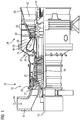
- FIG. 1 shows a stationary gas turbine 10 in a longitudinal partial section.
- the gas turbine 10 has inside a rotatably mounted about an axis of rotation 12 rotor 14, which is also referred to as a turbine runner.
- rotor 14 Along the rotor 14 follow one another an intake housing 16, a Axialturbover Noticer 18, a toroidal annular combustion chamber 20 with a plurality of rotationally symmetrically arranged burners 22, a turbine unit 24 and an exhaust housing 26.
- the gas turbine instead of an annular combustion chamber 20, the gas turbine with multiple tube combustion chambers with one or more Be equipped burners.
- the Axialturbover Noticer 18 includes a ring-shaped compressor duct 25 with successively cascaded compressor stages of blade and vane rings.
- the rotor blades 14 arranged on the blades 27 are opposed to an outer channel wall of the compressor passage 25.
- the compressor channel 25 opens via a compressor outlet diffuser 36 in a plenum 38.
- the combustion chamber 20 is provided with its combustion chamber 28, the communicates with an annular hot gas passage 30 of the turbine unit 24.
- four successive turbine stages 32 are arranged.
- a generator or a working machine (each not shown) is coupled. However, the number of turbine stages 32 is irrelevant to the invention.
- the axial turbocharger 18 draws in ambient air 34 through the intake housing 16 as a medium to be compressed and compresses it.
- the compressed air is guided through the compressor outlet diffuser 36 into the plenum 38, from where it flows into the burner 22.
- Fuel also passes into the combustion space 28 via the burners 22.
- the fuel is burned to a hot gas M with the addition of the compressed air.
- the hot gas M then flows into the hot gas duct 30, where it relaxes to perform work on the turbine blades of the turbine unit 24.
- the energy released during this time is absorbed by the rotor 14 and used on the one hand to drive the axial turbocharger 18 and on the other hand to drive a working machine or electric generator.
- the rotor 14 of the gas turbine 10 is supported on the housing 26 at its turbine-side end via a plurality of bearing struts 42 distributed along the circumference.
- a hydraulic bearing 44 is located in the center of the bearing struts 42 according to the embodiment.
- the hydraulic bearing 44 is provided as a radial bearing with corresponding bearing shells, in which the rotor 14 is hydrodynamically slidingly supported by means of the hydraulic oil.
- the bearing shells are in the interior of a bearing body 46 ( FIG. 2 ), wherein the bearing body 46 forms an oil sump 48 in its lower region relative to a horizontal plane 49. In other words, the oil pan 48 is part of the bearing body 46.
- this is used to lift the rotor 14 and to hydrodynamically support the rotor 14 during operation of the gas turbine 10 between the bearing shells and a rotor tread collected pressed in hydraulic oil.
- a circular discharge opening 50 is arranged, to which a vertical - so the foundation leading - drain line 52 is arranged.
- the outflow line 52 is set slightly inclined relative to a radial direction of the gas turbine and extends through a bearing strut 42 (not in FIG. 1) arranged in the lower half of the gas turbine 10 FIG. 2 shown).
- an insert 55 is provided.
- the insert 55 is in FIG. 2 merely schematically illustrated and comprises a disk-shaped plate 56 with a central opening 58 and a pipe 60 leading away from the opening.
- the pipe 60 extends down into the drainage pipe 52.
- the insert 55 and its components are in FIG. 2 only shown in longitudinal section.
- FIG. 3 The construction of the oil sump 48 with the insert 55 arranged on or in the discharge opening 50 is in FIG FIG. 3 shown schematically.
- the hydraulic oil used for lubricating the hydraulic bearing 44 must be reliably removed from the hydraulic bearing 44 after its use.
- two agents causing this are provided by means of the insert 55.
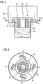
- the supports are designed as guide elements 54. They prevent hydraulic fluid flowing out mainly from flowing radially onto the circular discharge opening 50.
- the guide elements 54 direct outflowing hydraulic oil tangentially ( FIG. 4 . FIG. 5 ) in the drain opening 50, so that the hydraulic oil in after the drain line 52 flows with swirl. This causes the hydraulic oil to be applied to the wall of the drain line 52.
- a central air column can form in the center 62 of the drainage line 52, which connects the oil sump 48 with a drainage adjoining the drainage line 52.
- the formation of a central air column is also achieved or supported by the provision of the tube 60. This means also prevents a flow of hydraulic fluid completely flowing through the outflow line 52 in the center of the outflow opening 50, which if necessary leads to the formation of recurring oil plugs with a temporarily lower outflow quantity.
- the guide elements 54 according to the embodiment according to FIG. 5 differ from the guide elements 54 according to the embodiment FIG. 4 only in that they are not aligned obliquely, but parallel or perpendicular to Cartesian coordinate axes and offset at the same time. Even with such means, an annular outflow flow can be achieved with a tangential flow component.
- the guide elements 54 have a height H which is greater than the maximum expected in the oil pan 48 during operation oil level. This ensures that the hydraulic oil can not flow through the central, arranged in the plate 56 opening 58 and then flow through the pipe 60 into the drain line 52. It is also possible for the tube 60 to extend farther up into the room as illustrated. With such a tube extending through the plate 56, drainage of the hydraulic oil through the tube is particularly effectively prevented.
- the guide elements 54 may also be designed as struts with which the tube 60 arranged coaxially with the discharge line 52 can be fastened via the annular plate 56.
- the invention relates to a hydraulic bearing with an oil pan 48, in which a drain for hydraulic oil is provided, wherein the drain comprises a arranged in the oil pan 48 drain port 50 and a subsequent to the drain port 50 drain line 52.
- a drain for hydraulic oil is provided, wherein the drain comprises a arranged in the oil pan 48 drain port 50 and a subsequent to the drain port 50 drain line 52.
- means are provided which drain hydraulic oil in the outflow line 52 as a ring flow with a central air column.
Landscapes
- Engineering & Computer Science (AREA)
- General Engineering & Computer Science (AREA)
- Mechanical Engineering (AREA)
- Chemical & Material Sciences (AREA)
- Oil, Petroleum & Natural Gas (AREA)
- Hydraulic Turbines (AREA)
- Magnetic Bearings And Hydrostatic Bearings (AREA)
- Combustion & Propulsion (AREA)
- Support Of The Bearing (AREA)
- Sliding-Contact Bearings (AREA)
- Supercharger (AREA)
Description
- Die Erfindung betrifft ein Hydrauliklager für eine stationäre Gasturbine mit einer Ölwanne und mit einem Abfluss für Hydrauliköl.
- Ein gattungsgemäßes Hydrauliklager für eine Gasturbine ist beispielsweise aus der
WO 02/02913 A1 - Um einen kontinuierlichen Abfluss des Schmierfluids zu erreichen, ist aus der
EP 2 163 733 A3 bekannt, das Schmierfluid tangential in das Abflussrohr einströmen zu lassen. Jedoch erfordert diese Konstruktion eine vergleichsweise massive Ölwanne, was als nachteilig angesehen wird. - Aufgabe der Erfindung ist die Bereitstellung eines alternativen Hydrauliklagers für eine stationäre Gasturbine, welches ebenfalls bei kompakter Bauweise und unabhängig vom Betriebszustand der Gasturbine und von inneren Lagerdrücken einen zuverlässigen Abfluss von Hydrauliköl eines Anhebe- und/oder Schmierölsystems stets gewährleistet.
- Die der Erfindung zugrundeliegende Aufgabe wird mit einem Hydrauliklager gemäß den Merkmalen des Patentanspruchs 1 gelöst. Vorteilhafte Ausgestaltungen des Hydrauliklagers sind in den abhängigen Ansprüchen angegeben.
- Erfindungsgemäß ist vorgesehen, dass ein gattungsgemäßes Hydrauliklager mit Mitteln ausgestattet ist, die bei abfließendem Hydrauliköl in der Abflussleitung eine Ringströmung mit zentraler Luftsäule hervorrufen. Mit anderen Worten: die Mittel bewirken, dass das Hydrauliköl mit Drall entlang der Wand der Abflussleitung strömt, so dass sich im Inneren der Abflussleitung eine zentrale Luftsäule ausbilden kann, die ein diskontinuierliches Abfließen und das Bilden von wiederkehrenden Ölpfropfen in der Abflussleitung zuverlässig verhindert. Hierdurch kann ein Luftaustausch zwischen der Ölwanne und der nachgeordneten Drainage des Hydrauliklagers erfolgen, was zuverlässig einen vom Betriebsdruck bzw. Lagerinnendruck der Gasturbine unabhängigen und kontinuierlichen Abfluss von Hydrauliköl mit größerer Geschwindigkeit gewährleistet. Üblicherweise ist dabei die Abflussleitung zumindest ölwannenseitig als zur Horizontalebene nahezu senkrechtes Fallrohr ausgebildet, so dass die auf das Hydrauliköl einwirkende Schwerkraft das Abfließen bewirkt. Eine Vergrößerung des Querschnitts der Abflussleitung ist aufgrund der Erfindung nicht erforderlich.
- Gemäß einer ersten vorteilhaften Weiterbildung des Hydrauliklagers umfasst das Mittel um die Abflussöffnung herum angeordnete Leitelemente, die schräg zur Radialrichtung der Abflussöffnung angeordnet sind. Die Leitelemente behindern bzw. verhindern bestenfalls eine senkrecht auf die Abflussöffnung zuströmende Hydraulikölströmung. Sie erzwingen eine tangentiale Einströmung des Hydrauliköls in die Abflussöffnung und führen zu einer drallbehafteten Einströmung des Hydrauliköls nach Art eines Strudels. Die Leitelemente bilden mithin einen Drallkörper, der dem abfließenden Hydrauliköl die beschriebene tangentiale Geschwindigkeitskomponente aufprägt. Wegen der damit verbundenen Fliehkraft strömt das abfließende Hydrauliköl bevorzugt an der Wand der Abflussleitung, so dass sich in dessen Zentrum die zentrale Luftsäule für den Druckausgleich ausbilden kann. Die Luftsäule lässt somit das stoßweise Abfließen des Hydrauliköls nicht auftreten. Gleiches wird erreicht, wenn das Mittel alternativ versetzte Blockierungen umfasst.
- Gemäß einer weiteren vorteilhaften Ausgestaltung sind die Leitelemente an einer Unterseite einer scheibenförmigen Platte befestigt. Dadurch sind die Leitelemente zueinander stets in identischer Weise ausgerichtet und gegen Relativverschiebungen gesichert. Ein zuverlässiger Dauerbetrieb ist damit gewährleistet. Die Leitelemente und die Platte sind dann Teile eines Einsatzes, der wannenseitig in bestehende Hydrauliklager eingesetzt werden kann. Dies erleichtert das Nachrüsten bestehender Hydrauliklager.
- Besonders vorteilhaft ist die Ausgestaltung, bei der das Mittel ein sich in die Abflussleitung hinein erstreckendes, zur Abflussleitung koaxiales Rohr umfasst. Dieses Rohr bildet eine Hohlnabe, die immer eine Verbindung zwischen der Luft in einer Ölrücklaufleitung und der Luft in der Ölwanne herstellt. Auch dies verhindert die Bildung von wiederkehrenden Ölpfropfen und des damit einhergehenden diskontinuierlichen Abfließens in der bzw. durch die Abflussleitung.
- Besonders bevorzugt ist die Ausgestaltung, bei der die scheibenförmige Platte eine zentrale Öffnung aufweist, von dem aus sich das Rohr in die Abflussleitung erstreckt. Der so gebildete Einsatz lässt sich auch einfach in bestehende Hydrauliklager nachrüsten.
- Wenn die kreisförmige Abflussöffnung in einem ebenen Boden der Ölwanne angeordnet ist und die Abflussleitung sich von dort aus sich anfänglich nach unten erstreckt, kann ein kompaktes Hydrauliklager mit einem lokalen Sammelbereich angegeben werden.
- Zweckmäßigerweise ist die Ölwanne Teil eines Lagerkörpers, welcher zur Aufnahme und Lagerung eines Rotors der Gasturbine dient. Besonders bevorzugt ist die Verwendung des Hydrauliklagers in einer stationären Gasturbine, bei der sich die Abflussleitung durch eine Lagerstrebe erstreckt.
- Weitere Vorteile und Merkmale der Erfindung werden anhand der nachfolgenden Zeichnungen erläutert. Dabei zeigen:
- FIG 1
- eine Gasturbine durch einen Längsteilquerschnitt,
- FIG 2
- einen Ausschnitt aus dem Längsschnitt durch das Hydrauliklager der Gasturbine,
- FIG 3
- schematisch einen Längsschnitt durch eine Ölwanne des Hydrauliklagers mit in eine Abflussöffnung eingesetzten Einsatz,
- FIG 4
- den Querschnitt durch den Einsatz gemäß Schnittlinien IV-IV aus
FIG 3 und - FIG 5
- den Querschnitt analog zu
FIG 4 , nur mit einer geänderten Anordnung von Leitelementen. -
FIG 1 zeigt eine stationäre Gasturbine 10 in einem Längsteilschnitt. Die Gasturbine 10 weist im Innern einen um eine Rotationsachse 12 drehgelagerten Rotor 14 auf, der auch als Turbinenläufer bezeichnet wird. Entlang des Rotors 14 folgen aufeinander ein Ansauggehäuse 16, ein Axialturboverdichter 18, eine torusartige Ringbrennkammer 20 mit mehreren rotationssymmetrisch zueinander angeordneten Brennern 22, eine Turbineneinheit 24 und ein Abgasgehäuse 26. Anstelle mit einer Ringbrennkammer 20 kann die Gasturbine auch mit mehreren Rohrbrennkammern mit ein oder mehreren Brennern ausgestattet sein. - Der Axialturboverdichter 18 umfasst einen ringförmig ausgebildeten Verdichterkanal 25 mit darin kaskadisch aufeinanderfolgenden Verdichterstufen aus Laufschaufel- und Leitschaufelkränzen. Die am Rotor 14 angeordneten Laufschaufeln 27 liegen mit einer äußeren Kanalwand des Verdichterkanals 25 gegenüber. Der Verdichterkanal 25 mündet über einen Verdichterausgangsdiffusor 36 in einem Plenum 38. Darin ist die Brennkammer 20 mit ihrem Verbrennungsraum 28 vorgesehen, der mit einem ringförmigen Heißgaskanal 30 der Turbineneinheit 24 kommuniziert. In der Turbineneinheit 24 sind vier hintereinander geschaltete Turbinenstufen 32 angeordnet. Am Rotor 14 ist ein Generator oder eine Arbeitsmaschine (jeweils nicht dargestellt) angekoppelt. Die Anzahl der Turbinenstufen 32 ist jedoch für die Erfindung unerheblich.
- Im Betrieb der Gasturbine 10 saugt der Axialturboverdichter 18 durch das Ansauggehäuse 16 als zu verdichtendes Medium Umgebungsluft 34 an und verdichtet diese. Die verdichtete Luft wird durch den Verdichterausgangsdiffusor 36 in das Plenum 38 geführt, von wo aus es in die Brenner 22 einströmt. Über die Brenner 22 gelangt auch Brennstoff in den Verbrennungsraum 28. Dort wird der Brennstoff unter Zugabe der verdichteten Luft zu einem Heißgas M verbrannt. Das Heißgas M strömt anschließend in den Heißgaskanal 30, wo es sich arbeitsleistend an den Turbinenschaufeln der Turbineneinheit 24 entspannt. Die währenddessen freigesetzte Energie wird vom Rotor 14 aufgenommen und einerseits zum Antrieb des Axialturboverdichters 18 und andererseits zum Antrieb einer Arbeitsmaschine oder elektrischen Generators genutzt.
- Der Rotor 14 der Gasturbine 10 ist an seinem turbinenseitigen Ende über mehrere entlang des Umfangs verteilte Lagerstreben 42 am Gehäuse 26 abgestützt. Dazu ist gemäß dem Ausführungsbeispiel ein Hydrauliklager 44 im Zentrum der Lagerstreben 42 angesiedelt. Das Hydrauliklager 44 ist als Radiallager mit entsprechenden Lagerschalen ausgestattet, in denen der Rotor 14 hydrodynamisch mit Hilfe des Hydrauliköls gleitgelagert ist. Die Lagerschalen sind im Innern eines Lagerkörpers 46 (
FIG 2 ) angeordnet, wobei der Lagerkörper 46 in seinem - bezogen auf eine Horizontalebene 49 - unteren Bereich eine Ölwanne 48 bildet. Mit anderen Worten: die Ölwanne 48 ist Teil des Lagerkörpers 46. - In der Ölwanne 48 wird das zum Anheben des Rotors 14 und zur hydrodynamischen Lagerung des Rotors 14 während des Betriebs der Gasturbine 10 zwischen den Lagerschalen und einer Rotorlauffläche hineingepresste Hydrauliköl gesammelt. Dabei läuft das Hydrauliköl aufgrund der auf sie einwirkenden Gewichtskräfte in die Ölwanne 48. Im Boden 47 der Ölwanne 48 ist eine kreisförmige Abflussöffnung 50 angeordnet, an die eine vertikale - also zum Fundament hin führende - Abflussleitung 52 angeordnet ist. Im gezeigten Ausführungsbeispiel ist die Abflussleitung 52 gegenüber einer Radialrichtung der Gasturbine geringfügig geneigt angestellt und durchstreckt sich durch eine in der unteren Hälfte der Gasturbine 10 angeordneten Lagerstrebe 42 (nicht in
FIG 2 gezeigt). - Um die Bildung von wiederkehrenden Ölpfropfen in der Abflussleitung 52 und dem damit einhergehenden unstetigen Ölablauf zu vermeiden, ist ein Einsatz 55 vorgesehen. Der Einsatz 55 ist in
FIG 2 lediglich schematisch dargestellt und umfasst eine scheibenförmige Platte 56 mit einer zentralen Öffnung 58 und ein von der Öffnung wegführendes Rohr 60. Das Rohr 60 erstreckt sich nach unten bis in die Abflussleitung 52 hinein. Zudem umfasst der Einsatz 55 an der Unterseite der Platte 56 - also auf der der Abflussöffnung 50 zugewandten Seite der Platte 56 - über den Umfang der Abflussöffnung 50 gleichmäßig verteilte Stützen (FIG 4 ), die auf dem Wannenboden 47 aufsitzen. Auch der Einsatz 55 sowie dessen Bestandteile sind inFIG 2 lediglich im Längsschnitt dargestellt. - Der Aufbau der Ölwanne 48 mit dem am bzw. in der Abflussöffnung 50 angeordneten Einsatz 55 ist in
FIG 3 schematisch dargestellt. Das zur Schmierung des Hydrauliklagers 44 eingesetzte Hydrauliköl muss nach dessen Verwendung zuverlässig aus dem Hydrauliklager 44 abgeführt werden. Um einen kontinuierlichen Abfluss von Hydrauliköl aus der Ölwanne 48 mit erhöhtem Durchsatz zu gewährleisten, sind mit Hilfe des Einsatzes 55 zwei dies bewirkende Mittel vorgesehen. Zum einen sind die Stützen als Leitelemente 54 ausgebildet. Sie verhindern, dass abfließendes Hydrauliköl hauptsächlich radial auf die kreisrunde Abflussöffnung 50 zuströmt. Die Leitelemente 54 leiten abfließendes Hydrauliköl tangential (FIG 4 ,FIG 5 ) in die Abflussöffnung 50 ein, so dass das Hydrauliköl danach in der Abflussleitung 52 mit Drall abfließt. Dies führt dazu, dass das Hydrauliköl sich an die Wand der Abflussleitung 52 anlegt. Aufgrund dessen kann sich im Zentrum 62 der Abflussleitung 52 eine zentrale Luftsäule ausbilden, die die Ölwanne 48 mit einer sich an die Abflussleitung 52 anschließende Drainage verbindet. Die Ausbildung einer zentralen Luftsäule wird zum anderen auch durch das Vorsehen des Rohrs 60 erreicht bzw. unterstützt. Auch dieses Mittel verhindert, dass sich im Zentrum der Abflussöffnung 50 eine die Abflussleitung 52 vollständig durchströmende Hydraulikölströmung einstellt, die ggf. zur Bildung von wiederkehrenden Ölpfropfen mit zeitweise geringerer Abflussmenge führt. - Die Leitelemente 54 gemäß der Ausgestaltung nach
FIG 5 unterscheiden sich von den Leitelementen 54 gemäß der Ausgestaltung nachFIG 4 lediglich darin, dass diese nicht schräg, sondern parallel bzw. senkrecht zu kartesischen Koordinatenachsen und zugleich versetzt ausgerichtet sind. Auch mit derartigen Mitteln lässt sich eine ringförmige Abflussströmung mit einer tangentialen Strömungskomponente erreichen. - Die Leitelemente 54 weisen eine Höhe H auf, die größer ist als der in der Ölwanne 48 während des Betriebs maximal zu erwartende Ölstand. Dadurch ist gewährleistet, dass das Hydrauliköl nicht durch die zentrale, in der Platte 56 angeordnete Öffnung 58 einströmen und anschließend durch das Rohr 60 in die Abflussleitung 52 abfließen kann. Auch ist es möglich, dass das Rohr 60 weiter als dargestellt sich nach oben in den Raum erstrecken kann. Mit einem solchen, sich durch die Platte 56 hindurch erstreckendem Rohr wird das Abfließen des Hydrauliköls durch das Rohr besonders wirksam verhindert.
- Gleichzeitig können die Leitelemente 54 auch als Streben ausgebildet sein, mit denen das koaxial zur Abflussleitung 52 angeordnete Rohr 60 über die ringförmige Platte 56 befestigt werden kann.
- Insbesondere durch die gleichzeitige Verwendung der beiden Mittel zur Ausbildung einer Ringströmung aus Hydrauliköl mit einer zentralen Luftsäule in der Abflussleitung 52 eines Hydrauliklagers 44 wird besonders zuverlässig erreicht, dass unabhängig von dem Betriebszustand der Gasturbine 10 und unabhängig von Druckdifferenzen zwischen Lagerinnenraum und der Drainage des Ölsystems bei einem vertikalen Ölablauf der erforderliche Durchsatz an Hydrauliköl stets gewährleistet ist.
- Insgesamt betrifft die Erfindung ein Hydrauliklager mit einer Ölwanne 48, in der ein Abfluss für Hydrauliköl vorgesehen ist, wobei der Abfluss eine in der Ölwanne 48 angeordnete Abflussöffnung 50 und eine sich an die Abflussöffnung 50 anschließende Abflussleitung 52 umfasst. Um einen zuverlässigen und allein durch die Gewichtskraft bewerkstelligten Abfluss von Hydrauliköl zu ermöglichen, sind Mittel vorgesehen, die in der Abflussleitung 52 Hydrauliköl als Ringströmung mit zentraler Luftsäule abfließen lassen.
Claims (11)
- Hydrauliklager (44) für eine stationäre Gasturbine (10), mit einer Ölwanne (48), in der ein Abfluss für Hydrauliköl vorgesehen ist,
wobei der Abfluss eine in der Ölwanne (48) angeordnete Abflussöffnung (50) und eine sich an die Abflussöffnung (50) anschließende Abflussleitung (52) umfasst,
dadurch gekennzeichnet,
dass Mittel vorgesehen sind, die bei abfließendem Hydrauliköl in der Abflussleitung (52) eine Ringströmung mit zentraler Luftsäule bewirken. - Hydrauliklager (44) nach Anspruch 1,
bei der die Ringströmung eine tangentiale Strömungskomponente aufweist. - Hydrauliklager (44) nach Anspruch 1 oder 2,
bei der das Mittel um die Abflussöffnung (50) herum angeordnete Leitelemente (54) umfasst, die schräg zur Radialrichtung der Abflussöffnung (50) angeordnet sind. - Hydrauliklager (44) nach Anspruch 3,
bei dem die Leitelemente (54) an einer Unterseite einer scheibenförmigen Platte (56) angeordnet sind. - Hydrauliklager (44) nach Anspruch 1 oder 2,
bei der das Mittel alternativ versetzte Blockierungen umfasst. - Hydrauliklager (44) nach einem der vorangehenden Ansprüche,
bei dem das Mittel ein sich in die Abflussleitung (52) hineinstreckendes, zur Abflussleitung (52) koaxiales Rohr (60) umfasst. - Hydrauliklager (44) nach Anspruch 4 und 6,
bei dem die scheibenförmige Platte (56) eine zentrale Öffnung (58) aufweist, an dem sich das Rohr (60) anschließt. - Hydrauliklager (44) nach Anspruch 6 und 7,
bei dem das Rohr (60) sich durch die Platte (56) hindurch erstreckt. - Hydrauliklager (44) nach einem der Ansprüche 1 bis 8,
bei dem die Ölwanne (48) Teil eines Lagerkörpers ist, welcher zur Aufnahme und Lagerung eines Rotors (14) der Gasturbine (10) dient. - Hydrauliklager (44) nach einem der Ansprüche 1 bis 9
bei dem die Abflussöffnung (50) kreisförmig ausgestaltet und in einem Boden (47) der Ölwanne (48) angeordnet ist, wobei die sich an die Abflussöffnung (50) anschließende Abflussleitung (52) sich nach unten erstreckt. - Gasturbine (10) mit einem Hydrauliklager (44) nach einem der vorangehenden Ansprüche,
bei der der Abfluss sich durch eine Lagerstrebe (42) erstreckt.
Priority Applications (1)
| Application Number | Priority Date | Filing Date | Title |
|---|---|---|---|
| EP12728441.2A EP2699769B1 (de) | 2011-07-06 | 2012-06-11 | Hydrauliklager für eine stationäre gasturbine |
Applications Claiming Priority (3)
| Application Number | Priority Date | Filing Date | Title |
|---|---|---|---|
| EP11172856A EP2543832A1 (de) | 2011-07-06 | 2011-07-06 | Hydrauliklager für eine stationäre Gasturbine |
| PCT/EP2012/060970 WO2013004451A1 (de) | 2011-07-06 | 2012-06-11 | Hydrauliklager für eine stationäre gasturbine |
| EP12728441.2A EP2699769B1 (de) | 2011-07-06 | 2012-06-11 | Hydrauliklager für eine stationäre gasturbine |
Publications (2)
| Publication Number | Publication Date |
|---|---|
| EP2699769A1 EP2699769A1 (de) | 2014-02-26 |
| EP2699769B1 true EP2699769B1 (de) | 2016-04-27 |
Family
ID=46320911
Family Applications (2)
| Application Number | Title | Priority Date | Filing Date |
|---|---|---|---|
| EP11172856A Withdrawn EP2543832A1 (de) | 2011-07-06 | 2011-07-06 | Hydrauliklager für eine stationäre Gasturbine |
| EP12728441.2A Not-in-force EP2699769B1 (de) | 2011-07-06 | 2012-06-11 | Hydrauliklager für eine stationäre gasturbine |
Family Applications Before (1)
| Application Number | Title | Priority Date | Filing Date |
|---|---|---|---|
| EP11172856A Withdrawn EP2543832A1 (de) | 2011-07-06 | 2011-07-06 | Hydrauliklager für eine stationäre Gasturbine |
Country Status (6)
| Country | Link |
|---|---|
| US (1) | US9523288B2 (de) |
| EP (2) | EP2543832A1 (de) |
| JP (1) | JP5745173B2 (de) |
| CN (1) | CN103649478B (de) |
| RU (1) | RU2598498C2 (de) |
| WO (1) | WO2013004451A1 (de) |
Families Citing this family (1)
| Publication number | Priority date | Publication date | Assignee | Title |
|---|---|---|---|---|
| EP2853759A1 (de) | 2013-09-30 | 2015-04-01 | Siemens Aktiengesellschaft | Öllager mit Ölabflusssystem, Gasturbine mit einem solchen Öllager |
Family Cites Families (13)
| Publication number | Priority date | Publication date | Assignee | Title |
|---|---|---|---|---|
| US2616662A (en) * | 1949-01-05 | 1952-11-04 | Westinghouse Electric Corp | Turbine bearing support structure |
| SU832237A1 (ru) * | 1978-08-29 | 1981-05-23 | Уральский Филиал Всесоюзного Дваждыордена Трудового Красного Знаменитеплотехнического Научно-Исследо-Вательского Института Им. Ф.Э.Дзержинского | Система маслоснабжени узловТРЕНи и иСпОлНиТЕльНыХ МЕХАНизМОВ |
| DE3047719C2 (de) * | 1980-12-18 | 1983-10-27 | MTU Motoren- und Turbinen-Union München GmbH, 8000 München | Einrichtung zur Entlüftung eines Flüssigkeitsbehälters, insbesondere eines Schmiermittelbehälters für Flugzeuge bei extremen Fluglagen und -bedingungen |
| US4947963A (en) * | 1989-05-11 | 1990-08-14 | United Technologies Corporation | Oil supply reservoir |
| JPH0397512A (ja) | 1989-09-12 | 1991-04-23 | Bando Chem Ind Ltd | 電気絶縁軸受用外輪の製造方法 |
| JPH0397512U (de) * | 1990-01-25 | 1991-10-08 | ||
| CZ283260B6 (cs) | 1992-07-07 | 1998-02-18 | Siemens Aktiengesellschaft | Zařízení pro odvádění kapalného maziva z ložiskové sestavy |
| IT1319409B1 (it) | 2000-07-03 | 2003-10-10 | Nuovo Pignone Spa | Sistema di scarico per cuscini portanti di turbine a gas |
| DE10145478B4 (de) * | 2001-09-14 | 2007-01-18 | Erich Teufl | Hubkolbenmaschine mit umlaufendem Zylinder |
| US6996968B2 (en) * | 2003-12-17 | 2006-02-14 | United Technologies Corporation | Bifurcated oil scavenge system for a gas turbine engine |
| US7591631B2 (en) * | 2006-06-30 | 2009-09-22 | United Technologies Corporation | Flow delivery system for seals |
| US7878303B2 (en) * | 2006-11-14 | 2011-02-01 | Rolls-Royce Corporation | Lubrication scavenge system |
| GB0816562D0 (en) | 2008-09-11 | 2008-10-15 | Rolls Royce Plc | Lubricant scavenge arrangement |
-
2011
- 2011-07-06 EP EP11172856A patent/EP2543832A1/de not_active Withdrawn
-
2012
- 2012-06-11 US US14/129,953 patent/US9523288B2/en not_active Expired - Fee Related
- 2012-06-11 WO PCT/EP2012/060970 patent/WO2013004451A1/de not_active Ceased
- 2012-06-11 EP EP12728441.2A patent/EP2699769B1/de not_active Not-in-force
- 2012-06-11 CN CN201280033611.5A patent/CN103649478B/zh not_active Expired - Fee Related
- 2012-06-11 RU RU2014104032/06A patent/RU2598498C2/ru not_active IP Right Cessation
- 2012-06-11 JP JP2014517566A patent/JP5745173B2/ja not_active Expired - Fee Related
Also Published As
| Publication number | Publication date |
|---|---|
| CN103649478A (zh) | 2014-03-19 |
| US9523288B2 (en) | 2016-12-20 |
| EP2543832A1 (de) | 2013-01-09 |
| JP2014518350A (ja) | 2014-07-28 |
| WO2013004451A1 (de) | 2013-01-10 |
| EP2699769A1 (de) | 2014-02-26 |
| US20140147258A1 (en) | 2014-05-29 |
| RU2598498C2 (ru) | 2016-09-27 |
| JP5745173B2 (ja) | 2015-07-08 |
| CN103649478B (zh) | 2016-03-09 |
| RU2014104032A (ru) | 2015-08-20 |
Similar Documents
| Publication | Publication Date | Title |
|---|---|---|
| EP2024606B1 (de) | Ringförmiger strömungskanal für eine in axialrichtung von einem hauptstrom durchströmbare strömungsmaschine | |
| EP0924386B1 (de) | Verfahren und Vorrichtung zum berührungsfreien Abdichten eines zwischen einem Rotor und einem Stator ausgebildeten Trennspalts | |
| EP2123860B1 (de) | Kombinierter Wirbelgleichrichter | |
| EP3456945A1 (de) | Getriebe mit einem ölverteilungssystem | |
| EP2593643B1 (de) | Abgasdiffusor für eine gasturbine und verfahren zum betreiben einer gasturbine mit einem solchen abgasdiffusor | |
| DE4422700A1 (de) | Diffusor für Turbomaschine | |
| EP0834646A1 (de) | Berstschutzvorrichtung für Radialturbinen von Turboladern | |
| EP2685054B1 (de) | Diffusor einer abgasturbine | |
| WO2010063583A1 (de) | Ringdiffusor für eine axialturbomaschine | |
| EP1706597B1 (de) | Strömungsmaschine mit einem axial verschiebbaren rotor | |
| EP3064706A1 (de) | Leitschaufelreihe für eine axial durchströmte Strömungsmaschine | |
| EP2054587B1 (de) | Turbinengehäuse | |
| EP2561187A1 (de) | Abgasdiffusor einer gasturbine | |
| DE102010064025A1 (de) | Berstschutz | |
| DE10125250C1 (de) | Axialturbine eines Abgastruboladers mit internem Berstschutz | |
| EP2987967B1 (de) | Verdichtergehäuse für eine Gasturbine | |
| EP3164578B1 (de) | Abströmbereich einer turbine eines abgasturboladers | |
| EP2730744B1 (de) | Abgasturbolader | |
| EP2543832A1 (de) | Hydrauliklager für eine stationäre Gasturbine | |
| DE605003C (de) | Brennkraftturbine mit zwei gleichachsigen Wellen | |
| EP1687512B1 (de) | Turbolader mit einer reinigungsvorrichtung | |
| DE602005004432T2 (de) | Gasturbine | |
| EP1574667B1 (de) | Verdichterdiffusor | |
| EP2792855B1 (de) | Inneres Lagergehäuse eines Abgasturboladers | |
| DE102011005105B4 (de) | Austrittssammelgehäuse für einen Radialverdichter |
Legal Events
| Date | Code | Title | Description |
|---|---|---|---|
| PUAI | Public reference made under article 153(3) epc to a published international application that has entered the european phase |
Free format text: ORIGINAL CODE: 0009012 |
|
| 17P | Request for examination filed |
Effective date: 20131121 |
|
| AK | Designated contracting states |
Kind code of ref document: A1 Designated state(s): AL AT BE BG CH CY CZ DE DK EE ES FI FR GB GR HR HU IE IS IT LI LT LU LV MC MK MT NL NO PL PT RO RS SE SI SK SM TR |
|
| DAX | Request for extension of the european patent (deleted) | ||
| GRAP | Despatch of communication of intention to grant a patent |
Free format text: ORIGINAL CODE: EPIDOSNIGR1 |
|
| INTG | Intention to grant announced |
Effective date: 20151106 |
|
| GRAS | Grant fee paid |
Free format text: ORIGINAL CODE: EPIDOSNIGR3 |
|
| GRAA | (expected) grant |
Free format text: ORIGINAL CODE: 0009210 |
|
| AK | Designated contracting states |
Kind code of ref document: B1 Designated state(s): AL AT BE BG CH CY CZ DE DK EE ES FI FR GB GR HR HU IE IS IT LI LT LU LV MC MK MT NL NO PL PT RO RS SE SI SK SM TR |
|
| REG | Reference to a national code |
Ref country code: GB Ref legal event code: FG4D Free format text: NOT ENGLISH |
|
| REG | Reference to a national code |
Ref country code: CH Ref legal event code: EP |
|
| REG | Reference to a national code |
Ref country code: AT Ref legal event code: REF Ref document number: 795063 Country of ref document: AT Kind code of ref document: T Effective date: 20160515 |
|
| REG | Reference to a national code |
Ref country code: IE Ref legal event code: FG4D Free format text: LANGUAGE OF EP DOCUMENT: GERMAN |
|
| REG | Reference to a national code |
Ref country code: CH Ref legal event code: NV Representative=s name: SIEMENS SCHWEIZ AG, CH |
|
| REG | Reference to a national code |
Ref country code: DE Ref legal event code: R096 Ref document number: 502012006913 Country of ref document: DE |
|
| REG | Reference to a national code |
Ref country code: FR Ref legal event code: PLFP Year of fee payment: 5 |
|
| REG | Reference to a national code |
Ref country code: LT Ref legal event code: MG4D |
|
| REG | Reference to a national code |
Ref country code: NL Ref legal event code: MP Effective date: 20160427 |
|
| PG25 | Lapsed in a contracting state [announced via postgrant information from national office to epo] |
Ref country code: NL Free format text: LAPSE BECAUSE OF FAILURE TO SUBMIT A TRANSLATION OF THE DESCRIPTION OR TO PAY THE FEE WITHIN THE PRESCRIBED TIME-LIMIT Effective date: 20160427 |
|
| PG25 | Lapsed in a contracting state [announced via postgrant information from national office to epo] |
Ref country code: LT Free format text: LAPSE BECAUSE OF FAILURE TO SUBMIT A TRANSLATION OF THE DESCRIPTION OR TO PAY THE FEE WITHIN THE PRESCRIBED TIME-LIMIT Effective date: 20160427 Ref country code: NO Free format text: LAPSE BECAUSE OF FAILURE TO SUBMIT A TRANSLATION OF THE DESCRIPTION OR TO PAY THE FEE WITHIN THE PRESCRIBED TIME-LIMIT Effective date: 20160727 Ref country code: PL Free format text: LAPSE BECAUSE OF FAILURE TO SUBMIT A TRANSLATION OF THE DESCRIPTION OR TO PAY THE FEE WITHIN THE PRESCRIBED TIME-LIMIT Effective date: 20160427 Ref country code: FI Free format text: LAPSE BECAUSE OF FAILURE TO SUBMIT A TRANSLATION OF THE DESCRIPTION OR TO PAY THE FEE WITHIN THE PRESCRIBED TIME-LIMIT Effective date: 20160427 |
|
| PG25 | Lapsed in a contracting state [announced via postgrant information from national office to epo] |
Ref country code: SE Free format text: LAPSE BECAUSE OF FAILURE TO SUBMIT A TRANSLATION OF THE DESCRIPTION OR TO PAY THE FEE WITHIN THE PRESCRIBED TIME-LIMIT Effective date: 20160427 Ref country code: PT Free format text: LAPSE BECAUSE OF FAILURE TO SUBMIT A TRANSLATION OF THE DESCRIPTION OR TO PAY THE FEE WITHIN THE PRESCRIBED TIME-LIMIT Effective date: 20160829 Ref country code: ES Free format text: LAPSE BECAUSE OF FAILURE TO SUBMIT A TRANSLATION OF THE DESCRIPTION OR TO PAY THE FEE WITHIN THE PRESCRIBED TIME-LIMIT Effective date: 20160427 Ref country code: GR Free format text: LAPSE BECAUSE OF FAILURE TO SUBMIT A TRANSLATION OF THE DESCRIPTION OR TO PAY THE FEE WITHIN THE PRESCRIBED TIME-LIMIT Effective date: 20160728 Ref country code: RS Free format text: LAPSE BECAUSE OF FAILURE TO SUBMIT A TRANSLATION OF THE DESCRIPTION OR TO PAY THE FEE WITHIN THE PRESCRIBED TIME-LIMIT Effective date: 20160427 Ref country code: HR Free format text: LAPSE BECAUSE OF FAILURE TO SUBMIT A TRANSLATION OF THE DESCRIPTION OR TO PAY THE FEE WITHIN THE PRESCRIBED TIME-LIMIT Effective date: 20160427 Ref country code: LV Free format text: LAPSE BECAUSE OF FAILURE TO SUBMIT A TRANSLATION OF THE DESCRIPTION OR TO PAY THE FEE WITHIN THE PRESCRIBED TIME-LIMIT Effective date: 20160427 |
|
| PG25 | Lapsed in a contracting state [announced via postgrant information from national office to epo] |
Ref country code: BE Free format text: LAPSE BECAUSE OF NON-PAYMENT OF DUE FEES Effective date: 20160630 |
|
| REG | Reference to a national code |
Ref country code: DE Ref legal event code: R097 Ref document number: 502012006913 Country of ref document: DE |
|
| PG25 | Lapsed in a contracting state [announced via postgrant information from national office to epo] |
Ref country code: RO Free format text: LAPSE BECAUSE OF FAILURE TO SUBMIT A TRANSLATION OF THE DESCRIPTION OR TO PAY THE FEE WITHIN THE PRESCRIBED TIME-LIMIT Effective date: 20160427 Ref country code: CZ Free format text: LAPSE BECAUSE OF FAILURE TO SUBMIT A TRANSLATION OF THE DESCRIPTION OR TO PAY THE FEE WITHIN THE PRESCRIBED TIME-LIMIT Effective date: 20160427 Ref country code: MC Free format text: LAPSE BECAUSE OF FAILURE TO SUBMIT A TRANSLATION OF THE DESCRIPTION OR TO PAY THE FEE WITHIN THE PRESCRIBED TIME-LIMIT Effective date: 20160427 Ref country code: DK Free format text: LAPSE BECAUSE OF FAILURE TO SUBMIT A TRANSLATION OF THE DESCRIPTION OR TO PAY THE FEE WITHIN THE PRESCRIBED TIME-LIMIT Effective date: 20160427 Ref country code: EE Free format text: LAPSE BECAUSE OF FAILURE TO SUBMIT A TRANSLATION OF THE DESCRIPTION OR TO PAY THE FEE WITHIN THE PRESCRIBED TIME-LIMIT Effective date: 20160427 Ref country code: SK Free format text: LAPSE BECAUSE OF FAILURE TO SUBMIT A TRANSLATION OF THE DESCRIPTION OR TO PAY THE FEE WITHIN THE PRESCRIBED TIME-LIMIT Effective date: 20160427 |
|
| PG25 | Lapsed in a contracting state [announced via postgrant information from national office to epo] |
Ref country code: SM Free format text: LAPSE BECAUSE OF FAILURE TO SUBMIT A TRANSLATION OF THE DESCRIPTION OR TO PAY THE FEE WITHIN THE PRESCRIBED TIME-LIMIT Effective date: 20160427 |
|
| PLBE | No opposition filed within time limit |
Free format text: ORIGINAL CODE: 0009261 |
|
| STAA | Information on the status of an ep patent application or granted ep patent |
Free format text: STATUS: NO OPPOSITION FILED WITHIN TIME LIMIT |
|
| REG | Reference to a national code |
Ref country code: IE Ref legal event code: MM4A |
|
| 26N | No opposition filed |
Effective date: 20170130 |
|
| PG25 | Lapsed in a contracting state [announced via postgrant information from national office to epo] |
Ref country code: SI Free format text: LAPSE BECAUSE OF FAILURE TO SUBMIT A TRANSLATION OF THE DESCRIPTION OR TO PAY THE FEE WITHIN THE PRESCRIBED TIME-LIMIT Effective date: 20160427 Ref country code: IE Free format text: LAPSE BECAUSE OF NON-PAYMENT OF DUE FEES Effective date: 20160611 |
|
| REG | Reference to a national code |
Ref country code: FR Ref legal event code: PLFP Year of fee payment: 6 |
|
| REG | Reference to a national code |
Ref country code: CH Ref legal event code: PCOW Free format text: NEW ADDRESS: WERNER-VON-SIEMENS-STRASSE 1, 80333 MUENCHEN (DE) |
|
| PG25 | Lapsed in a contracting state [announced via postgrant information from national office to epo] |
Ref country code: HU Free format text: LAPSE BECAUSE OF FAILURE TO SUBMIT A TRANSLATION OF THE DESCRIPTION OR TO PAY THE FEE WITHIN THE PRESCRIBED TIME-LIMIT; INVALID AB INITIO Effective date: 20120611 Ref country code: CY Free format text: LAPSE BECAUSE OF FAILURE TO SUBMIT A TRANSLATION OF THE DESCRIPTION OR TO PAY THE FEE WITHIN THE PRESCRIBED TIME-LIMIT Effective date: 20160427 |
|
| REG | Reference to a national code |
Ref country code: FR Ref legal event code: PLFP Year of fee payment: 7 |
|
| PG25 | Lapsed in a contracting state [announced via postgrant information from national office to epo] |
Ref country code: LU Free format text: LAPSE BECAUSE OF NON-PAYMENT OF DUE FEES Effective date: 20160611 Ref country code: TR Free format text: LAPSE BECAUSE OF FAILURE TO SUBMIT A TRANSLATION OF THE DESCRIPTION OR TO PAY THE FEE WITHIN THE PRESCRIBED TIME-LIMIT Effective date: 20160427 Ref country code: MK Free format text: LAPSE BECAUSE OF FAILURE TO SUBMIT A TRANSLATION OF THE DESCRIPTION OR TO PAY THE FEE WITHIN THE PRESCRIBED TIME-LIMIT Effective date: 20160427 Ref country code: IS Free format text: LAPSE BECAUSE OF FAILURE TO SUBMIT A TRANSLATION OF THE DESCRIPTION OR TO PAY THE FEE WITHIN THE PRESCRIBED TIME-LIMIT Effective date: 20160427 Ref country code: MT Free format text: LAPSE BECAUSE OF FAILURE TO SUBMIT A TRANSLATION OF THE DESCRIPTION OR TO PAY THE FEE WITHIN THE PRESCRIBED TIME-LIMIT Effective date: 20160427 |
|
| PG25 | Lapsed in a contracting state [announced via postgrant information from national office to epo] |
Ref country code: BG Free format text: LAPSE BECAUSE OF FAILURE TO SUBMIT A TRANSLATION OF THE DESCRIPTION OR TO PAY THE FEE WITHIN THE PRESCRIBED TIME-LIMIT Effective date: 20160427 |
|
| REG | Reference to a national code |
Ref country code: AT Ref legal event code: MM01 Ref document number: 795063 Country of ref document: AT Kind code of ref document: T Effective date: 20170611 |
|
| PGFP | Annual fee paid to national office [announced via postgrant information from national office to epo] |
Ref country code: FR Payment date: 20180614 Year of fee payment: 7 |
|
| PG25 | Lapsed in a contracting state [announced via postgrant information from national office to epo] |
Ref country code: AL Free format text: LAPSE BECAUSE OF FAILURE TO SUBMIT A TRANSLATION OF THE DESCRIPTION OR TO PAY THE FEE WITHIN THE PRESCRIBED TIME-LIMIT Effective date: 20160427 |
|
| PGFP | Annual fee paid to national office [announced via postgrant information from national office to epo] |
Ref country code: DE Payment date: 20180820 Year of fee payment: 7 Ref country code: IT Payment date: 20180627 Year of fee payment: 7 Ref country code: GB Payment date: 20180614 Year of fee payment: 7 |
|
| PG25 | Lapsed in a contracting state [announced via postgrant information from national office to epo] |
Ref country code: AT Free format text: LAPSE BECAUSE OF NON-PAYMENT OF DUE FEES Effective date: 20170611 |
|
| PGFP | Annual fee paid to national office [announced via postgrant information from national office to epo] |
Ref country code: CH Payment date: 20180910 Year of fee payment: 7 |
|
| REG | Reference to a national code |
Ref country code: DE Ref legal event code: R119 Ref document number: 502012006913 Country of ref document: DE |
|
| REG | Reference to a national code |
Ref country code: CH Ref legal event code: PL |
|
| GBPC | Gb: european patent ceased through non-payment of renewal fee |
Effective date: 20190611 |
|
| PG25 | Lapsed in a contracting state [announced via postgrant information from national office to epo] |
Ref country code: DE Free format text: LAPSE BECAUSE OF NON-PAYMENT OF DUE FEES Effective date: 20200101 Ref country code: GB Free format text: LAPSE BECAUSE OF NON-PAYMENT OF DUE FEES Effective date: 20190611 Ref country code: IT Free format text: LAPSE BECAUSE OF NON-PAYMENT OF DUE FEES Effective date: 20190611 |
|
| PG25 | Lapsed in a contracting state [announced via postgrant information from national office to epo] |
Ref country code: LI Free format text: LAPSE BECAUSE OF NON-PAYMENT OF DUE FEES Effective date: 20190630 Ref country code: CH Free format text: LAPSE BECAUSE OF NON-PAYMENT OF DUE FEES Effective date: 20190630 |
|
| PG25 | Lapsed in a contracting state [announced via postgrant information from national office to epo] |
Ref country code: FR Free format text: LAPSE BECAUSE OF NON-PAYMENT OF DUE FEES Effective date: 20190630 |