EP2698552B1 - Fixation antivol avec fonction de verrouillage - Google Patents
Fixation antivol avec fonction de verrouillage Download PDFInfo
- Publication number
- EP2698552B1 EP2698552B1 EP13178660.0A EP13178660A EP2698552B1 EP 2698552 B1 EP2698552 B1 EP 2698552B1 EP 13178660 A EP13178660 A EP 13178660A EP 2698552 B1 EP2698552 B1 EP 2698552B1
- Authority
- EP
- European Patent Office
- Prior art keywords
- nut
- casing
- disposed
- lock
- hole
- Prior art date
- Legal status (The legal status is an assumption and is not a legal conclusion. Google has not performed a legal analysis and makes no representation as to the accuracy of the status listed.)
- Not-in-force
Links
- 238000004891 communication Methods 0.000 claims description 3
- 238000000034 method Methods 0.000 description 3
- 230000003466 anti-cipated effect Effects 0.000 description 1
- 239000000428 dust Substances 0.000 description 1
- 238000002474 experimental method Methods 0.000 description 1
- 238000012986 modification Methods 0.000 description 1
- 230000004048 modification Effects 0.000 description 1
- 238000009877 rendering Methods 0.000 description 1
- 238000011160 research Methods 0.000 description 1
Images


Classifications
-
- F—MECHANICAL ENGINEERING; LIGHTING; HEATING; WEAPONS; BLASTING
- F16—ENGINEERING ELEMENTS AND UNITS; GENERAL MEASURES FOR PRODUCING AND MAINTAINING EFFECTIVE FUNCTIONING OF MACHINES OR INSTALLATIONS; THERMAL INSULATION IN GENERAL
- F16B—DEVICES FOR FASTENING OR SECURING CONSTRUCTIONAL ELEMENTS OR MACHINE PARTS TOGETHER, e.g. NAILS, BOLTS, CIRCLIPS, CLAMPS, CLIPS OR WEDGES; JOINTS OR JOINTING
- F16B41/00—Measures against loss of bolts, nuts, or pins; Measures against unauthorised operation of bolts, nuts or pins
- F16B41/005—Measures against unauthorised operation of bolts, nuts or pins
-
- B—PERFORMING OPERATIONS; TRANSPORTING
- B62—LAND VEHICLES FOR TRAVELLING OTHERWISE THAN ON RAILS
- B62H—CYCLE STANDS; SUPPORTS OR HOLDERS FOR PARKING OR STORING CYCLES; APPLIANCES PREVENTING OR INDICATING UNAUTHORIZED USE OR THEFT OF CYCLES; LOCKS INTEGRAL WITH CYCLES; DEVICES FOR LEARNING TO RIDE CYCLES
- B62H5/00—Appliances preventing or indicating unauthorised use or theft of cycles; Locks integral with cycles
- B62H5/001—Preventing theft of parts or accessories used on cycles, e.g. lamp, dynamo
Definitions
- the present invention relates to anti-theft fastener with locking feature, particularly to a fastener with its' polygonal nut providing with locking feature therein a fastener so as to prevent the nut from being loosened and thereby to reach the purpose of anti-theft.
- the external wall surface of a nut which meshes with a bolt or a screw is usually hexagonal.
- the internal wall surface of the nut has an inner thread.
- a sleeve or a wrench is used to grip the hexagonal external wall surface of the nut to thereby fasten the nut to the bolt or the screw or unfasten the nut from the bolt or the screw.
- the nut typically lacks a locking feature, and thus in the situation where precious articles are fixed by a fastener in place, such as fastening the wheels to wheel axle of a bicycle, fastening hub to wheel rim of a vehicle's tire, or, fastening storage battery to a vehicle, the articles are targets to theft, as a conventional sleeve or wrench can be fitted around the nut to loosen or tighten it. In general, fastener cannot prevent from be stolen.
- the inventor of the present invention conducted extensive researches and experiments according to the inventor's years of experience in the related industry, and finally developed an anti-theft fastener with locking feature as disclosed in the present invention.
- GB 360 304 A discloses a device for securing articles by means of a nut or bolt comprising two main parts capable of being rendered rotatable independently of one another.
- the security against unauthorized unscrewing or screwing up of the operated part is obtained by rendering the two main parts independently of one another in only one of the directions of rotation, while allowing them to engage in the reverse direction of rotation.
- the objective of the present invention is to provide an anti-theft fastener with locking feature capable of being firmly fastened to a bolt or a screw and manifesting anti-theft.
- the anti-theft fastener with locking feature of the present invention is comprised of : a nut having therein a concave chamber and having an end provided with a flange, the concave chamber having therein an inner screw hole extending to and being in communication with an outer end of the flange, wherein at least a position-limiting hole is disposed on the external wall surface of the nut and communicates with the concave chamber of the nut, the at least a position-limiting hole having therein a positioning ball, wherein at least a receiving groove is disposed on an outer end side of the concave chamber of the nut, wherein a spring and an ejecting pin are disposed in the receiving groove of the nut; a ring disposed on the flange of the nut; a nut casing disposed outside the nut, the
- At least a positioning engaging passage is disposed on an end side of the lock casing to accommodate the ejecting pin of the nut.
- the lock and the lock casing are positioned inside the nut casing.
- the abutting portion of the lock no longer abuts against the positioning ball of the nut.
- the positioning ball of the nut is no longer embedded in the positioning engaging passage of the nut casing.
- the user only needs to turn the lock by using a key, such that the engaging ball of the lock casing falls into the curved groove of the lock, whereas the engaging ball exits the engaging groove of the nut casing, and thus the ejecting pin is pushed outward because of the resilient restoration of the spring.
- the lock casing is pushed outward by the ejecting pin, whereas the lock casing drives the lock to move outward together.
- the abutting portion of the lock pushes the positioning ball of the nut outward such that the positioning ball is embedded in the positioning engaging passage of the nut casing, thereby allowing the nut casing to drive the nut to rotate. Accordingly, the anti-theft fastener with locking feature can be unfastened from the bolt or the screw.
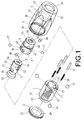
- an anti-theft fastener with locking feature essentially comprises a nut 1, a ring 2, a nut casing 3, a lock casing 4, and a lock 5.
- a flange 10 is disposed at one end of the nut 1.
- the nut 1 has therein a concave chamber 11.
- the concave chamber 11 has therein an inner thread hole 12 extending to and being in communication with the outside of the flange 10.
- At least a position-limiting hole 13 is disposed on the outer wall surface of the nut 1.
- the at least a position-limiting hole 13 extends to and communicates with the concave chamber 11.
- a positioning ball 14 is disposed inside the at least a position-limiting hole 13.
- At least a receiving groove 15 is disposed on the outer end side of the concave chamber 11 of the nut 1.
- the receiving groove 15 received therein a spring 16 and an ejecting pin 17.
- the ring 2 is disposed on the flange 10 of the nut 1.
- the ring 2 has a through hole 20.
- An outer thread 21 is disposed on the external wall surface of the ring 2.
- the nut casing 3 is disposed outside the nut 1.
- Polygonal facets 30 are disposed on the external wall surface of the nut casing 3.
- the nut casing 3 has therein a receiving chamber 31 and a receiving channel 32.
- An engaging groove 33 is disposed between the receiving chamber 31 and the receiving channel 32.
- An inner thread 34 is disposed at the outer end of the receiving chamber 31.
- the receiving chamber 31 has therein at least a positioning engaging passage 35.
- the positioning engaging passage 35 corresponds in position to the positioning ball 14 of the nut 1.
- a through hole 36 is disposed at the outer end of the receiving channel 32.
- the lock casing 4 is disposed inside the receiving channel 32 of the nut casing 3.
- a press portion 40 is disposed at one end of the lock casing 4.
- the lock casing 4 has therein a receiving chamber 41.
- the press portion 40 has a through hole 42 passing through the receiving chamber 41.
- a guide groove 43 is disposed on the inner wall surface of the receiving chamber 41.
- At least a pin hole 44 and at least a position-limiting hole 45 are disposed on the wall surface of the lock casing 4.
- a fixing pin 46 is disposed inside the pin hole 44.
- An engaging ball 47 is disposed inside the at least a position-limiting hole 45. At least a positioning engaging passage 48 is disposed on an end side of the lock casing 4.
- the lock 5 is disposed inside the receiving chamber 41 of the lock casing 4.
- a drilling-proof plate 50 is disposed at one end of the lock 5.
- the drilling-proof plate 50 has a keyhole 51.
- Plurality locking plates 52 are disposed inside the lock 5.
- At least a curved groove 53 is disposed on the wall surface of the lock 5.
- a guide strip 54 is disposed on the wall surface of the lock 5.
- the guide strip 54 is disposed inside the guide groove 43 of the lock casing 4.
- An abutting portion 55 is disposed at the other end of the lock 5.
- An annular groove 56 is disposed on the lock 5. Given the aforesaid structures and arrangement thereof, an anti-theft fastener with locking feature is formed.
- an assembly process involves putting the lock 5 into the receiving chamber 41 of the lock casing 4, putting the guide strip 54 of the lock 5 into the guide groove 43 of the lock casing 4, putting the fixing pin 46 into the pin hole 44 of the lock casing 4, putting the fixing pin 46 into the at least a curved groove 53 of the lock 5, positioning the lock 5 into the lock casing 4, putting the engaging ball 47 into the position-limiting hole 45 of the lock casing 4, positioning a portion of the engaging ball 47 inside the curved groove 53 of the lock 5, putting the lock casing 4 and the lock 5 which have been put together into the receiving channel 32 of the nut casing 3, protruding the press portion 40 of the lock casing 4 out of the through hole 36 of the nut casing 3, putting the spring 16 and the ejecting pin 17 in the receiving groove 15 of the nut 1 in sequence, protruding a portion of the ejecting pin 17 out of the receiving groove 15, putting the positioning ball 14 in the position-limiting hole 13 of the
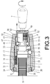
- a user's operation of the anti-theft fastener with locking feature is described as follows. As soon as the press portion 40 of the lock casing 4 protrudes outward to stick out of the nut casing 3, the abutting portion 55 of the lock 5 abuts against the positioning ball 14 inside the position-limiting hole 13 of the nut 1, such that the positioning ball 14 cannot retract but is firmly embedded in the positioning engaging passage 35 of the nut casing 3.
- the anti-theft fastener with locking feature is either fastened or unfastened as shown in FIG. 3 .
- the positioning ball 14 can move into the annular groove 56, and thus the positioning ball 14 is no longer embedded in the positioning engaging passage 35 of the nut casing 3. As a result, the nut casing 3 and the nut 1 are no longer engaged with each other. As soon as a sleeve or a wrench is fitted around the nut casing 3 and turned, the nut casing 3 fails to drive the nut 1 but starts idling; hence, the anti-theft fastener with locking feature of the present invention cannot be rotated and dismounted from the bolt 6 or a screw. In doing so, the anti-theft fastener with locking feature can be firmly locked to the bolt 6 or the screw of an article to thereby manifest anti-theft.
- the user inserts the key 7 into the keyhole 51 of the lock 5, and rotates the key 7 to drive the lock 5 to rotate until the curved groove 53 of the lock 5 faces the position-limiting hole 45 of the lock casing 4 squarely.
- the engaging ball 47 inside the position-limiting hole 45 moves into the curved groove 53 of the lock 5 and exits the engaging groove 33 of the nut casing 3, such that the engaging ball 47 is no longer embedded in the engaging groove 33 of the nut casing 3, whereas the spring 16 inside the receiving groove 15 of the nut 1 restores to its original state resiliently and pushes the ejecting pin 17 outward.
- the ejecting pin 17 pushes the lock casing 4 outward, whereas the lock casing 4 drives the lock 5 to move together; meanwhile, the press portion 40 the lock casing 4 protrudes outward once again, whereas the abutting portion 55 of the lock 5 pushes the positioning ball 14 outward once again, such that a portion of the positioning ball 14 is embedded in the positioning engaging passage 35 of the nut casing 3.
- the nut casing 3 drives the nut 1 to rotates, such that the anti-theft fastener with locking feature can be released from the bolt 6 or the screw to thereby finalize the dismounting operation.
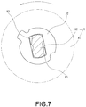
- FIG. 6 shows another embodiment of the present invention, which further comprises a dustproof cover 8 having a cover body 81 and an insert 82 connected to the cover body 81.
- the insert 82 is installed into the keyhole 51 of the lock 5, as shown in FIG. 7 , such that the cover body 81 conceals the keyhole 51 and prevents the keyhole 51 from being blocked by the slit/dust.
- the insert 82 of the dustproof cover 8 has notches 83 respectively disposed on the opposite corners thereof.
- the notches 83 are corresponding to one of the plurality of locking plates 52 of the lock 5, such that said one of the plurality of locking plates 52 is unaligned with another locking plate 52, as shown in FIG. 8 , when the dustproof cover 8 is rotated.
- the insert 82 of the dustproof cover 8 is stopped and positioned thereby and prevented from dropping out of the keyhole 51.
- the cover body 81 of the dustproof cover 8 further has a tool part 84 thereon for improving the ease of use. When the tool part 84 is joined with a handheld tool by the user, the dustproof cover 8 is driven to rotate.
- the present invention not only achieves the anticipated objectives and advantages, but is also more satisfactory and practical than the prior art.
- the aforesaid embodiment is illustrative of the present invention only, but should not be interpreted as restrictive of the scope of the present invention.
- all equivalent changes and modifications made to the aforesaid embodiment without departing from the technical solution disclosed in the present invention should fall within the scope of the present invention.
Landscapes
- Engineering & Computer Science (AREA)
- General Engineering & Computer Science (AREA)
- Mechanical Engineering (AREA)
- Snaps, Bayonet Connections, Set Pins, And Snap Rings (AREA)
- Transmission Devices (AREA)
Claims (2)
- Un système d'attache antivol avec une fonction de verrouillage, comprenant :un écrou (1) présentant à l'intérieur une chambre concave (11) et présentant une extrémité munie d'un rebord (10), la chambre concave (11) présentant à l'intérieur un trou de vis intérieur (12) se prolongeant vers et étant en communication avec une extrémité extérieure du rebord (10), caractérisé en ce qu'au moins un trou de limitation de position (13) est disposé sur la surface de la paroi extérieure de l'écrou (1) et communique avec la chambre concave (11) de l'écrou (1), au moins un trou de limitation de position (13) présentant à l'intérieur une boule de positionnement (14), dans lequel au moins une rainure de réception (15) est disposée sur un côté d'une extrémité extérieure de la chambre concave (11) de l'écrou (1), dans lequel un ressort (16) et une barrette d'éjection (17) sont disposés dans la rainure de réception (15) de l'écrou (1) ;un anneau (2) disposé autour du rebord (10) de l'écrou (1) ;un boîtier d'écrou (3) renfermant l'écrou (1), le boîtier d'écrou (3) présentant à l'intérieur une chambre de réception (31) et un canal de réception (32), dans lequel une rainure d'engagement (33) est disposée entre le canal de réception (32) et la chambre de réception (31) du boîtier d'écrou (3), dans lequel au moins un passage d'engagement de positionnement (35) est disposé dans la chambre de réception (31) du boîtier d'écrou (3) et correspond en position à la boule de positionnement (14) de l'écrou (1), dans lequel un trou traversant (36) est disposé à une extrémité extérieure du canal de réception (32) du boîtier d'écrou (3) ;un boîtier de verrou (4) disposé dans le canal de réception (32) du boîtier d'écrou (3), dans lequel une partie de presse (40) est disposée à une extrémité du boîtier de verrou (4) et insérée dans le trou traversant (36) du boîtier d'écrou (3), le boîtier de verrou (4) présentant à l'intérieur une chambre de réception (41), la partie de pression (40) présentant un trou traversant (42) passant à travers la chambre de réception (41) du boîtier de verrou (4), dans lequel une rainure de guidage (43) est disposée sur une surface de paroi interne de la chambre de réception (41) du boîtier de verrou (4), dans lequel au moins un trou de cheville (44) et au moins un trou de limitation de position (45) sont disposés sur une surface de paroi du boîtier de verrou (4), au moins un trou de cheville (44) présentant à l'intérieur une cheville de fixation (46), au moins un trou de limitation de position (45) présentant à l'intérieur une boule d'engagement (47) ; etun verrou (5) disposé dans la chambre de réception (41) du boîtier de verrou (4) et présentant une rainure annulaire (56), dans lequel une barre de guidage (54) et au moins une rainure courbée (53) sont disposées sur une surface de paroi du verrou (5), la barre de guidage (54) étant disposée dans la rainure de guidage (43) du boîtier de verrou (4), dans lequel une partie de butée (55) est disposée à une extrémité du verrou (5).
- Le système d'attache antivol selon la revendication 1, dans lequel au moins un passage d'engagement de positionnement (48) est disposé sur un côté d'extrémité du boîtier de verrou (4) pour loger la barrette d'éjection (17) de l'écrou (1).
Applications Claiming Priority (1)
| Application Number | Priority Date | Filing Date | Title |
|---|---|---|---|
| TW101129443A TW201407050A (zh) | 2012-08-14 | 2012-08-14 | 防盜螺件 |
Publications (2)
| Publication Number | Publication Date |
|---|---|
| EP2698552A1 EP2698552A1 (fr) | 2014-02-19 |
| EP2698552B1 true EP2698552B1 (fr) | 2016-04-27 |
Family
ID=48900835
Family Applications (1)
| Application Number | Title | Priority Date | Filing Date |
|---|---|---|---|
| EP13178660.0A Not-in-force EP2698552B1 (fr) | 2012-08-14 | 2013-07-31 | Fixation antivol avec fonction de verrouillage |
Country Status (2)
| Country | Link |
|---|---|
| EP (1) | EP2698552B1 (fr) |
| TW (1) | TW201407050A (fr) |
Families Citing this family (10)
| Publication number | Priority date | Publication date | Assignee | Title |
|---|---|---|---|---|
| CN104775691B (zh) * | 2015-04-14 | 2017-07-07 | 深圳市纽贝尔电子有限公司 | 一种螺钉电子锁装置 |
| CN108488194B (zh) * | 2018-06-09 | 2023-06-09 | 海盐卫士标准件有限公司 | 一种不易拧松的防盗螺母 |
| MX2019005377A (es) * | 2019-05-08 | 2019-10-07 | Gildardo Blanco Barrera Gudalupe | Dispositivo de seguridad para medios de rodamiento de vehiculos. |
| CN111457000B (zh) * | 2020-04-30 | 2024-05-24 | 宁波金海仪表有限公司 | 一种防盗螺母 |
| CN111636767B (zh) * | 2020-06-02 | 2024-08-02 | 厦门美科物联科技有限公司 | 一种锁具结构 |
| CN111669917A (zh) * | 2020-06-12 | 2020-09-15 | 杭州元朗智能科技有限公司 | 一种新能源电池充放维护仪 |
| CN111749968B (zh) * | 2020-07-03 | 2021-08-10 | 珠海优特电力科技股份有限公司 | 用于螺母闭锁的锁具及锁具组件 |
| CN113550665B (zh) * | 2021-07-09 | 2022-07-22 | 瑞尔工业股份有限公司 | 自行车锁 |
| TWI795941B (zh) * | 2021-10-08 | 2023-03-11 | 恒昌行精密工業有限公司 | 板對板定位裝置 |
| CN117553067B (zh) * | 2023-12-12 | 2026-01-09 | 广州时易中信息科技有限公司 | 防盗手拧螺母结构 |
Family Cites Families (6)
| Publication number | Priority date | Publication date | Assignee | Title |
|---|---|---|---|---|
| FR706469A (fr) * | 1930-02-24 | 1931-06-24 | écrou et serrure combinés en vue de rendre, à volonté, impossible le dévissage ou le vissage de l'écrou | |
| US5027628A (en) * | 1990-04-27 | 1991-07-02 | Omnilock Incorporated | Lockable quick-release mechanism |
| US5007260A (en) * | 1990-06-29 | 1991-04-16 | Harry Sharp | Bicycle locking system |
| JP4112138B2 (ja) * | 1999-11-24 | 2008-07-02 | 美和ロック株式会社 | 螺合具 |
| CN201209355Y (zh) * | 2008-05-28 | 2009-03-18 | 徐恩 | 嵌式车轮螺母防盗锁 |
| TWM382363U (en) * | 2009-11-13 | 2010-06-11 | Jing-Han Lv | Lock head-type anti-theft screw device |
-
2012
- 2012-08-14 TW TW101129443A patent/TW201407050A/zh not_active IP Right Cessation
-
2013
- 2013-07-31 EP EP13178660.0A patent/EP2698552B1/fr not_active Not-in-force
Also Published As
| Publication number | Publication date |
|---|---|
| TWI448625B (fr) | 2014-08-11 |
| TW201407050A (zh) | 2014-02-16 |
| EP2698552A1 (fr) | 2014-02-19 |
Similar Documents
| Publication | Publication Date | Title |
|---|---|---|
| EP2698552B1 (fr) | Fixation antivol avec fonction de verrouillage | |
| US8820126B2 (en) | Anti-theft fastener with locking feature | |
| US10486461B1 (en) | Wheel lock with central expander | |
| US6116700A (en) | Lockable automotive wheel with splined adapter | |
| US9051962B2 (en) | Fastener | |
| US20190234449A1 (en) | Wheel Lock for an Automobile | |
| US8099984B2 (en) | Tire lock | |
| CN112543705B (zh) | 具有中心膨胀件的轮锁 | |
| JP4730721B1 (ja) | 盗難防止用ボルト及び盗難防止用ボルトに用いられる治具 | |
| US6609401B1 (en) | Car wheel anti-theft device | |
| US5758523A (en) | Lock construction for automotive spare wheel winch | |
| CN103591113B (zh) | 防盗螺件 | |
| US8061169B2 (en) | Locking system with hidden keyed access | |
| TWI710487B (zh) | 輪胎鎖具 | |
| TW202128458A (zh) | 輪鎖定裝置 | |
| CN114379505B (zh) | 一种车轮锁 | |
| CA2463451A1 (fr) | Ensemble de protection d'ecrou antivol | |
| CN102059913A (zh) | 防盗轮毂 | |
| CA2622576C (fr) | Systeme de verrouillage a acces par cle cache | |
| JPS62175201A (ja) | 自動車用センタ−ロツク装置 | |
| JPS59190001A (ja) | センタ−ホイ−ルのロツク装置 | |
| JPS6141601Y2 (fr) | ||
| JPS6018401A (ja) | ホイ−ルロツク | |
| JPS6331901Y2 (fr) | ||
| JP3091948U (ja) | シリンダ錠用カラー構造 |
Legal Events
| Date | Code | Title | Description |
|---|---|---|---|
| AK | Designated contracting states |
Kind code of ref document: A1 Designated state(s): AL AT BE BG CH CY CZ DE DK EE ES FI FR GB GR HR HU IE IS IT LI LT LU LV MC MK MT NL NO PL PT RO RS SE SI SK SM TR |
|
| AX | Request for extension of the european patent |
Extension state: BA ME |
|
| PUAI | Public reference made under article 153(3) epc to a published international application that has entered the european phase |
Free format text: ORIGINAL CODE: 0009012 |
|
| 17P | Request for examination filed |
Effective date: 20140131 |
|
| RBV | Designated contracting states (corrected) |
Designated state(s): AL AT BE BG CH CY CZ DE DK EE ES FI FR GB GR HR HU IE IS IT LI LT LU LV MC MK MT NL NO PL PT RO RS SE SI SK SM TR |
|
| GRAP | Despatch of communication of intention to grant a patent |
Free format text: ORIGINAL CODE: EPIDOSNIGR1 |
|
| INTG | Intention to grant announced |
Effective date: 20151104 |
|
| GRAS | Grant fee paid |
Free format text: ORIGINAL CODE: EPIDOSNIGR3 |
|
| GRAA | (expected) grant |
Free format text: ORIGINAL CODE: 0009210 |
|
| AK | Designated contracting states |
Kind code of ref document: B1 Designated state(s): AL AT BE BG CH CY CZ DE DK EE ES FI FR GB GR HR HU IE IS IT LI LT LU LV MC MK MT NL NO PL PT RO RS SE SI SK SM TR |
|
| REG | Reference to a national code |
Ref country code: GB Ref legal event code: FG4D |
|
| REG | Reference to a national code |
Ref country code: CH Ref legal event code: EP |
|
| REG | Reference to a national code |
Ref country code: FR Ref legal event code: PLFP Year of fee payment: 4 |
|
| REG | Reference to a national code |
Ref country code: AT Ref legal event code: REF Ref document number: 795149 Country of ref document: AT Kind code of ref document: T Effective date: 20160515 |
|
| REG | Reference to a national code |
Ref country code: IE Ref legal event code: FG4D |
|
| REG | Reference to a national code |
Ref country code: DE Ref legal event code: R096 Ref document number: 602013006898 Country of ref document: DE |
|
| REG | Reference to a national code |
Ref country code: NL Ref legal event code: FP |
|
| REG | Reference to a national code |
Ref country code: LT Ref legal event code: MG4D |
|
| REG | Reference to a national code |
Ref country code: AT Ref legal event code: MK05 Ref document number: 795149 Country of ref document: AT Kind code of ref document: T Effective date: 20160427 |
|
| PG25 | Lapsed in a contracting state [announced via postgrant information from national office to epo] |
Ref country code: LT Free format text: LAPSE BECAUSE OF FAILURE TO SUBMIT A TRANSLATION OF THE DESCRIPTION OR TO PAY THE FEE WITHIN THE PRESCRIBED TIME-LIMIT Effective date: 20160427 Ref country code: FI Free format text: LAPSE BECAUSE OF FAILURE TO SUBMIT A TRANSLATION OF THE DESCRIPTION OR TO PAY THE FEE WITHIN THE PRESCRIBED TIME-LIMIT Effective date: 20160427 Ref country code: PL Free format text: LAPSE BECAUSE OF FAILURE TO SUBMIT A TRANSLATION OF THE DESCRIPTION OR TO PAY THE FEE WITHIN THE PRESCRIBED TIME-LIMIT Effective date: 20160427 Ref country code: NO Free format text: LAPSE BECAUSE OF FAILURE TO SUBMIT A TRANSLATION OF THE DESCRIPTION OR TO PAY THE FEE WITHIN THE PRESCRIBED TIME-LIMIT Effective date: 20160727 |
|
| PG25 | Lapsed in a contracting state [announced via postgrant information from national office to epo] |
Ref country code: LV Free format text: LAPSE BECAUSE OF FAILURE TO SUBMIT A TRANSLATION OF THE DESCRIPTION OR TO PAY THE FEE WITHIN THE PRESCRIBED TIME-LIMIT Effective date: 20160427 Ref country code: GR Free format text: LAPSE BECAUSE OF FAILURE TO SUBMIT A TRANSLATION OF THE DESCRIPTION OR TO PAY THE FEE WITHIN THE PRESCRIBED TIME-LIMIT Effective date: 20160728 Ref country code: AT Free format text: LAPSE BECAUSE OF FAILURE TO SUBMIT A TRANSLATION OF THE DESCRIPTION OR TO PAY THE FEE WITHIN THE PRESCRIBED TIME-LIMIT Effective date: 20160427 Ref country code: SE Free format text: LAPSE BECAUSE OF FAILURE TO SUBMIT A TRANSLATION OF THE DESCRIPTION OR TO PAY THE FEE WITHIN THE PRESCRIBED TIME-LIMIT Effective date: 20160427 Ref country code: RS Free format text: LAPSE BECAUSE OF FAILURE TO SUBMIT A TRANSLATION OF THE DESCRIPTION OR TO PAY THE FEE WITHIN THE PRESCRIBED TIME-LIMIT Effective date: 20160427 Ref country code: PT Free format text: LAPSE BECAUSE OF FAILURE TO SUBMIT A TRANSLATION OF THE DESCRIPTION OR TO PAY THE FEE WITHIN THE PRESCRIBED TIME-LIMIT Effective date: 20160829 Ref country code: HR Free format text: LAPSE BECAUSE OF FAILURE TO SUBMIT A TRANSLATION OF THE DESCRIPTION OR TO PAY THE FEE WITHIN THE PRESCRIBED TIME-LIMIT Effective date: 20160427 Ref country code: ES Free format text: LAPSE BECAUSE OF FAILURE TO SUBMIT A TRANSLATION OF THE DESCRIPTION OR TO PAY THE FEE WITHIN THE PRESCRIBED TIME-LIMIT Effective date: 20160427 |
|
| PG25 | Lapsed in a contracting state [announced via postgrant information from national office to epo] |
Ref country code: IT Free format text: LAPSE BECAUSE OF FAILURE TO SUBMIT A TRANSLATION OF THE DESCRIPTION OR TO PAY THE FEE WITHIN THE PRESCRIBED TIME-LIMIT Effective date: 20160427 Ref country code: BE Free format text: LAPSE BECAUSE OF FAILURE TO SUBMIT A TRANSLATION OF THE DESCRIPTION OR TO PAY THE FEE WITHIN THE PRESCRIBED TIME-LIMIT Effective date: 20160427 |
|
| REG | Reference to a national code |
Ref country code: DE Ref legal event code: R097 Ref document number: 602013006898 Country of ref document: DE |
|
| PG25 | Lapsed in a contracting state [announced via postgrant information from national office to epo] |
Ref country code: EE Free format text: LAPSE BECAUSE OF FAILURE TO SUBMIT A TRANSLATION OF THE DESCRIPTION OR TO PAY THE FEE WITHIN THE PRESCRIBED TIME-LIMIT Effective date: 20160427 Ref country code: CZ Free format text: LAPSE BECAUSE OF FAILURE TO SUBMIT A TRANSLATION OF THE DESCRIPTION OR TO PAY THE FEE WITHIN THE PRESCRIBED TIME-LIMIT Effective date: 20160427 Ref country code: DK Free format text: LAPSE BECAUSE OF FAILURE TO SUBMIT A TRANSLATION OF THE DESCRIPTION OR TO PAY THE FEE WITHIN THE PRESCRIBED TIME-LIMIT Effective date: 20160427 Ref country code: SK Free format text: LAPSE BECAUSE OF FAILURE TO SUBMIT A TRANSLATION OF THE DESCRIPTION OR TO PAY THE FEE WITHIN THE PRESCRIBED TIME-LIMIT Effective date: 20160427 Ref country code: RO Free format text: LAPSE BECAUSE OF FAILURE TO SUBMIT A TRANSLATION OF THE DESCRIPTION OR TO PAY THE FEE WITHIN THE PRESCRIBED TIME-LIMIT Effective date: 20160427 |
|
| PG25 | Lapsed in a contracting state [announced via postgrant information from national office to epo] |
Ref country code: SM Free format text: LAPSE BECAUSE OF FAILURE TO SUBMIT A TRANSLATION OF THE DESCRIPTION OR TO PAY THE FEE WITHIN THE PRESCRIBED TIME-LIMIT Effective date: 20160427 |
|
| REG | Reference to a national code |
Ref country code: CH Ref legal event code: PL |
|
| PLBE | No opposition filed within time limit |
Free format text: ORIGINAL CODE: 0009261 |
|
| STAA | Information on the status of an ep patent application or granted ep patent |
Free format text: STATUS: NO OPPOSITION FILED WITHIN TIME LIMIT |
|
| PG25 | Lapsed in a contracting state [announced via postgrant information from national office to epo] |
Ref country code: MC Free format text: LAPSE BECAUSE OF FAILURE TO SUBMIT A TRANSLATION OF THE DESCRIPTION OR TO PAY THE FEE WITHIN THE PRESCRIBED TIME-LIMIT Effective date: 20160427 |
|
| 26N | No opposition filed |
Effective date: 20170130 |
|
| PG25 | Lapsed in a contracting state [announced via postgrant information from national office to epo] |
Ref country code: LI Free format text: LAPSE BECAUSE OF NON-PAYMENT OF DUE FEES Effective date: 20160731 Ref country code: CH Free format text: LAPSE BECAUSE OF NON-PAYMENT OF DUE FEES Effective date: 20160731 |
|
| REG | Reference to a national code |
Ref country code: IE Ref legal event code: MM4A |
|
| PG25 | Lapsed in a contracting state [announced via postgrant information from national office to epo] |
Ref country code: SI Free format text: LAPSE BECAUSE OF FAILURE TO SUBMIT A TRANSLATION OF THE DESCRIPTION OR TO PAY THE FEE WITHIN THE PRESCRIBED TIME-LIMIT Effective date: 20160427 |
|
| REG | Reference to a national code |
Ref country code: FR Ref legal event code: PLFP Year of fee payment: 5 |
|
| PG25 | Lapsed in a contracting state [announced via postgrant information from national office to epo] |
Ref country code: IE Free format text: LAPSE BECAUSE OF NON-PAYMENT OF DUE FEES Effective date: 20160731 |
|
| PG25 | Lapsed in a contracting state [announced via postgrant information from national office to epo] |
Ref country code: LU Free format text: LAPSE BECAUSE OF NON-PAYMENT OF DUE FEES Effective date: 20160731 |
|
| PGFP | Annual fee paid to national office [announced via postgrant information from national office to epo] |
Ref country code: FR Payment date: 20170710 Year of fee payment: 5 |
|
| PG25 | Lapsed in a contracting state [announced via postgrant information from national office to epo] |
Ref country code: CY Free format text: LAPSE BECAUSE OF FAILURE TO SUBMIT A TRANSLATION OF THE DESCRIPTION OR TO PAY THE FEE WITHIN THE PRESCRIBED TIME-LIMIT Effective date: 20160427 Ref country code: HU Free format text: LAPSE BECAUSE OF FAILURE TO SUBMIT A TRANSLATION OF THE DESCRIPTION OR TO PAY THE FEE WITHIN THE PRESCRIBED TIME-LIMIT; INVALID AB INITIO Effective date: 20130731 |
|
| PG25 | Lapsed in a contracting state [announced via postgrant information from national office to epo] |
Ref country code: MT Free format text: LAPSE BECAUSE OF NON-PAYMENT OF DUE FEES Effective date: 20160731 Ref country code: IS Free format text: LAPSE BECAUSE OF FAILURE TO SUBMIT A TRANSLATION OF THE DESCRIPTION OR TO PAY THE FEE WITHIN THE PRESCRIBED TIME-LIMIT Effective date: 20160427 Ref country code: MK Free format text: LAPSE BECAUSE OF FAILURE TO SUBMIT A TRANSLATION OF THE DESCRIPTION OR TO PAY THE FEE WITHIN THE PRESCRIBED TIME-LIMIT Effective date: 20160427 Ref country code: TR Free format text: LAPSE BECAUSE OF FAILURE TO SUBMIT A TRANSLATION OF THE DESCRIPTION OR TO PAY THE FEE WITHIN THE PRESCRIBED TIME-LIMIT Effective date: 20160427 |
|
| PG25 | Lapsed in a contracting state [announced via postgrant information from national office to epo] |
Ref country code: BG Free format text: LAPSE BECAUSE OF FAILURE TO SUBMIT A TRANSLATION OF THE DESCRIPTION OR TO PAY THE FEE WITHIN THE PRESCRIBED TIME-LIMIT Effective date: 20160427 |
|
| PG25 | Lapsed in a contracting state [announced via postgrant information from national office to epo] |
Ref country code: AL Free format text: LAPSE BECAUSE OF FAILURE TO SUBMIT A TRANSLATION OF THE DESCRIPTION OR TO PAY THE FEE WITHIN THE PRESCRIBED TIME-LIMIT Effective date: 20160427 |
|
| PG25 | Lapsed in a contracting state [announced via postgrant information from national office to epo] |
Ref country code: FR Free format text: LAPSE BECAUSE OF NON-PAYMENT OF DUE FEES Effective date: 20180731 |
|
| PGFP | Annual fee paid to national office [announced via postgrant information from national office to epo] |
Ref country code: DE Payment date: 20190904 Year of fee payment: 7 |
|
| PGFP | Annual fee paid to national office [announced via postgrant information from national office to epo] |
Ref country code: NL Payment date: 20200722 Year of fee payment: 8 |
|
| PGFP | Annual fee paid to national office [announced via postgrant information from national office to epo] |
Ref country code: GB Payment date: 20200722 Year of fee payment: 8 |
|
| REG | Reference to a national code |
Ref country code: DE Ref legal event code: R119 Ref document number: 602013006898 Country of ref document: DE |
|
| PG25 | Lapsed in a contracting state [announced via postgrant information from national office to epo] |
Ref country code: DE Free format text: LAPSE BECAUSE OF NON-PAYMENT OF DUE FEES Effective date: 20210202 |
|
| REG | Reference to a national code |
Ref country code: NL Ref legal event code: MM Effective date: 20210801 |
|
| GBPC | Gb: european patent ceased through non-payment of renewal fee |
Effective date: 20210731 |
|
| PG25 | Lapsed in a contracting state [announced via postgrant information from national office to epo] |
Ref country code: GB Free format text: LAPSE BECAUSE OF NON-PAYMENT OF DUE FEES Effective date: 20210731 |
|
| PG25 | Lapsed in a contracting state [announced via postgrant information from national office to epo] |
Ref country code: NL Free format text: LAPSE BECAUSE OF NON-PAYMENT OF DUE FEES Effective date: 20210801 |