EP2698332A2 - Device for winding of a strip-like material on reels - Google Patents
Device for winding of a strip-like material on reels Download PDFInfo
- Publication number
- EP2698332A2 EP2698332A2 EP13003624.7A EP13003624A EP2698332A2 EP 2698332 A2 EP2698332 A2 EP 2698332A2 EP 13003624 A EP13003624 A EP 13003624A EP 2698332 A2 EP2698332 A2 EP 2698332A2
- Authority
- EP
- European Patent Office
- Prior art keywords
- rotary body
- rotary
- end position
- winding axis
- winding
- Prior art date
- Legal status (The legal status is an assumption and is not a legal conclusion. Google has not performed a legal analysis and makes no representation as to the accuracy of the status listed.)
- Granted
Links
- 238000004804 winding Methods 0.000 title claims description 32
- 239000000463 material Substances 0.000 title claims description 14
- 241000252254 Catostomidae Species 0.000 claims 3
- 244000085320 Opuntia triacanthos Species 0.000 description 10
- 230000008859 change Effects 0.000 description 4
- 230000008901 benefit Effects 0.000 description 3
- 238000004080 punching Methods 0.000 description 3
- 101100390736 Danio rerio fign gene Proteins 0.000 description 1
- 101100390738 Mus musculus Fign gene Proteins 0.000 description 1
- 240000001439 Opuntia Species 0.000 description 1
- 235000004727 Opuntia ficus indica Nutrition 0.000 description 1
- 238000010276 construction Methods 0.000 description 1
- 238000009826 distribution Methods 0.000 description 1
- 239000013013 elastic material Substances 0.000 description 1
- 238000004870 electrical engineering Methods 0.000 description 1
- 238000009713 electroplating Methods 0.000 description 1
- 230000006872 improvement Effects 0.000 description 1
- 235000015095 lager Nutrition 0.000 description 1
- 238000004519 manufacturing process Methods 0.000 description 1
- 230000007246 mechanism Effects 0.000 description 1
- 238000000034 method Methods 0.000 description 1
- 229920001296 polysiloxane Polymers 0.000 description 1
- 230000008569 process Effects 0.000 description 1
- 230000001360 synchronised effect Effects 0.000 description 1
Images


Classifications
-
- B—PERFORMING OPERATIONS; TRANSPORTING
- B65—CONVEYING; PACKING; STORING; HANDLING THIN OR FILAMENTARY MATERIAL
- B65H—HANDLING THIN OR FILAMENTARY MATERIAL, e.g. SHEETS, WEBS, CABLES
- B65H18/00—Winding webs
- B65H18/08—Web-winding mechanisms
-
- B—PERFORMING OPERATIONS; TRANSPORTING
- B65—CONVEYING; PACKING; STORING; HANDLING THIN OR FILAMENTARY MATERIAL
- B65H—HANDLING THIN OR FILAMENTARY MATERIAL, e.g. SHEETS, WEBS, CABLES
- B65H19/00—Changing the web roll
- B65H19/22—Changing the web roll in winding mechanisms or in connection with winding operations
- B65H19/2207—Changing the web roll in winding mechanisms or in connection with winding operations the web roll being driven by a winding mechanism of the centre or core drive type
-
- B—PERFORMING OPERATIONS; TRANSPORTING
- B65—CONVEYING; PACKING; STORING; HANDLING THIN OR FILAMENTARY MATERIAL
- B65H—HANDLING THIN OR FILAMENTARY MATERIAL, e.g. SHEETS, WEBS, CABLES
- B65H18/00—Winding webs
- B65H18/08—Web-winding mechanisms
- B65H18/10—Mechanisms in which power is applied to web-roll spindle
-
- B—PERFORMING OPERATIONS; TRANSPORTING
- B65—CONVEYING; PACKING; STORING; HANDLING THIN OR FILAMENTARY MATERIAL
- B65H—HANDLING THIN OR FILAMENTARY MATERIAL, e.g. SHEETS, WEBS, CABLES
- B65H19/00—Changing the web roll
- B65H19/22—Changing the web roll in winding mechanisms or in connection with winding operations
- B65H19/2207—Changing the web roll in winding mechanisms or in connection with winding operations the web roll being driven by a winding mechanism of the centre or core drive type
- B65H19/2215—Turret-type with two roll supports
-
- B—PERFORMING OPERATIONS; TRANSPORTING
- B65—CONVEYING; PACKING; STORING; HANDLING THIN OR FILAMENTARY MATERIAL
- B65H—HANDLING THIN OR FILAMENTARY MATERIAL, e.g. SHEETS, WEBS, CABLES
- B65H19/00—Changing the web roll
- B65H19/22—Changing the web roll in winding mechanisms or in connection with winding operations
- B65H19/2207—Changing the web roll in winding mechanisms or in connection with winding operations the web roll being driven by a winding mechanism of the centre or core drive type
- B65H19/223—Changing the web roll in winding mechanisms or in connection with winding operations the web roll being driven by a winding mechanism of the centre or core drive type with roll supports being independently displaceable along a common path
-
- B—PERFORMING OPERATIONS; TRANSPORTING
- B65—CONVEYING; PACKING; STORING; HANDLING THIN OR FILAMENTARY MATERIAL
- B65H—HANDLING THIN OR FILAMENTARY MATERIAL, e.g. SHEETS, WEBS, CABLES
- B65H2301/00—Handling processes for sheets or webs
- B65H2301/40—Type of handling process
- B65H2301/41—Winding, unwinding
- B65H2301/413—Supporting web roll
- B65H2301/4136—Mounting arrangements not otherwise provided for
- B65H2301/41368—Mounting arrangements not otherwise provided for one or two lateral flanges covering part of or entire web diameter
- B65H2301/413683—Mounting arrangements not otherwise provided for one or two lateral flanges covering part of or entire web diameter at least one flange transmitting driving force
-
- B—PERFORMING OPERATIONS; TRANSPORTING
- B65—CONVEYING; PACKING; STORING; HANDLING THIN OR FILAMENTARY MATERIAL
- B65H—HANDLING THIN OR FILAMENTARY MATERIAL, e.g. SHEETS, WEBS, CABLES
- B65H2701/00—Handled material; Storage means
- B65H2701/10—Handled articles or webs
- B65H2701/19—Specific article or web
- B65H2701/1942—Web supporting regularly spaced non-adhesive articles
Definitions
- the invention relates to a device for winding strip-shaped material according to claim 1.
- contact elements for electrical engineering are now produced in large quantities by punching.
- the contact elements leave the punching machine attached to at least one carrier strip so that a band-shaped material is present, which consists of the aforementioned at least one carrier strip and the stamped contact parts.
- the strip-shaped material is wound onto coils. Cardboard bobbins are often used for this purpose.
- cardboard spools have the advantage of a low price and a low weight, which keeps the transport costs low. They also have the advantage that they can be recycled immediately after use.
- Such a cardboard spool has a spool core and two circular side walls, which are held on the spool core and, ideally, extend parallel to one another.
- a device for winding the strip-like material on such a coil has in the simplest case a drive motor which can set a rotary body in rotation. From this rotary body extends a shaft on which the coil is attached. From the rotary body further extend, for example, mandrels, which drill in a side wall of such a cardboard spool, so that a temporary rotationally fixed connection between the rotary body and the cardboard spool is formed.
- the coils, when full, are changed by a person by hand.
- a problem that often occurs with the use of the above-mentioned cardboard reels is that the parallelism of the side walls is not ideally preserved, namely such that the side walls are slightly wavy, especially in the edge region. In the worst case, this can lead to the band-shaped material to be wound becoming caught on a side wall of the cardboard spool, which can lead to damage to the produced parts (usually contacts) or to a machine downtime because the winding up has to be interrupted.
- the present invention has the object to provide a device for winding tape-shaped material available, which works well even if the used cardboard spools have side walls with bumps.
- the device according to the invention has at least one first rotary body which can be rotated about a winding axis and a second rotary body which can be rotated about the winding axis. From one of these two rotary body preferably extends a shaft.
- the second rotary body is axially movable with respect to the winding axis from a first end position to a second end position, wherein the second rotary body is closer to the first rotary body in the first end position than in the second end position.
- At least one rotary drive is provided, by means of which the two rotary bodies can at least then be set in rotation together about the winding axis when the second rotary body is in its second end position.
- a coil in particular a cardboard spool, held and positioned between the two rotating bodies.
- At least one of the two rotary bodies - preferably both - carries holding elements for pulling in each case a side wall of a coil, for which purpose the holding elements each have a holding side, which is movable relative to the rotary body.
- At least one side wall of a coil can be pulled from outside into a defined position.
- This position can either be such that the side walls are completely parallel to each other, or even such that the distance between the two side walls defined increases from inside to outside, which can additionally facilitate the shrinkage of the strip-shaped material.
- This defined influencing of the shape of the side walls of the coils is preferably carried out fully automatically.
- the holding elements are, as already mentioned, preferably designed as pneumatic suckers, wherein these are further preferably designed such that they have a greater length in a state in which they are not subjected to negative pressure than in a state, in which they are subjected to negative pressure.
- pneumatic suckers are known in the art and are available as a standard component on the market.
- each first rotary body 10a, 10b carries a plurality of pneumatic suckers 32, which serve as holding elements.
- this pneumatic sucker 32 will be later with reference to the FIGS. 17 and 18 received.
- These pneumatic suckers 32 extend in a longitudinal direction parallel to the shafts 14a, 14b.
- the device further has a movable arm 28, which has a rotatable about the winding axis S second rotary body 20. This can be offset by a drive motor 26 in a corresponding rotational movement.
- This second rotary body has, just like the two first rotary bodies 10a, 10b, a thickened hub region 22 and pneumatic suction pads 32 serving as holding elements. Each rotary body preferably carries in symmetrical distribution four to eight such pneumatic suction pads 32, wherein in the FIG. 1 only two are shown.
- the second rotary body 20 has no waves but a recess 23 which is coaxial with the winding axis.
- the movable arm 28 (and thus also the second rotary body 20) is movable parallel to the winding axis S from a first to a second end position, wherein in FIG. 1 the second end position is shown, in which the second rotary body 20 has its maximum distance from the first rotary bodies.
- the drive mechanism for the movable arm 28 is in FIG. 1 not shown.
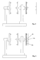
- FIG. 1 schematically shown a coil 50. This consists of a coil core 52 and two circular disk-shaped side walls 54 held on the coil core 52.
- the material of the coil 50 is, as already mentioned, cardboard.
- FIGS. 17 to 19 show schematic sectional views of a pneumatic cleaner 32, as it is preferably used in the present invention.
- the pneumatic sucker 32 is made of an elastic material such as rubber or silicone.
- the pneumatic sucker 32 extends along an axial direction (this is parallel to the winding axis during winding; the pneumatic suckers of the second rotating body always extend parallel to the winding axis) from a connection side 34 to a suction side 36.
- the middle section 38 extending therebetween formed in the form of a bellows.
- the suction side 36 is completely open or has at least one hole.
- the connection side 34 is fixedly connected to the respective rotary body.
- the suction side 36 in contact with a substantially planar object (this is the outer surface of a side wall 54 of a coil 50 in the inventive device) and the connection side 34 is connected to a suction pump, it is due to the fact that the hole the suction side 36 is closed by the object, within the pneumatic suction 32 to a negative pressure, whereby this exerts a force in the direction F on the substantially planar object. If the corresponding object can move in this direction, the middle section 38 contracts and pulls the object in the direction F. The suction side 36 thus forms the holding side of the pneumatic suction device.
- FIG. 1 the pneumatic suckers 32 are shown in a state in which they have their maximum length, in which they extend slightly beyond the thickened hub regions 12a, 12b, 22 in the axial direction.
- FIG. 2 shows the same as that FIG. 1 namely a state in which no coil 50 is arranged on a rotary body.
- This state can occur, for example, when the punching machine that delivers the strip-shaped material that is to be wound up on reels 50 starts fresh after a production interruption.
- at least one coil is always arranged on a first rotary body, as will be seen later.
- a coil 50 is attached to the shaft 14b of the first rotary body 10b, which faces away from the second rotary body 20. This is in FIG. 3 shown.
- the vertical arm rotates by 180 ° and brings the first rotary body 10b in the FIG. 4 shown position in which it is opposite to the second rotary body 20.
- the two shafts 14a, 14b are of course not coaxial with the winding axis, after reaching the in FIG. 4 However, this condition is fulfilled again.
- the second rotary body 20 moved by means of its movable arm 28 in its first end position, in which the Spool core 52 is clamped between the hub portions 12b and 22 is held and all pneumatic suction pads 32 are lightly pressed against the side walls 54 of the held between the rotating bodies 10b, 20 coil 50.
- the shaft 14b extends into the recess 23. This makes it possible to use coils of different thickness.
- the pneumatic suckers are now operated (ie supplied with negative pressure), so that they are trapped on the outer sides of the side walls 54 and pull them outwards, so that the in FIG. 6 shown state occurs.
- the curvature of the side walls 54 to the outside is exaggerated strong here.
- the first rotary body 10b and the second rotary body 20 are now rotated about the winding axis, wherein in the illustrated embodiment, the two drive motors 16b and 26 are used, which are synchronized to each other.
- the two drive motors 16b and 26 are used, which are synchronized to each other.
- the band-shaped material is now wound on the spool core 52 (see FIGS. 7 and 8th ), so that a winding 60 is formed.
- a new spool 50 ' is provided and mounted on the shaft 14a of the outwardly facing first rotating body 10a. If the coil 50 is full, the drive motors 16b and 26 are stopped and the second rotary body 20 is moved back to its second end position, so that the in FIG. 9 shown condition prevails.
- the vertical arm 18 is now again pivoted by 180 ° about its vertical pivot axis S, so that the empty coil 50 'is now in a state corresponding to FIG. 4 located. It begins now a new cycle.
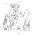
- FIGS. 12 to 15 Now, a second embodiment of the invention will be described.
- the basic structure is identical to the same described embodiment; Similar components are therefore provided with the same reference numerals as in the first embodiment.
- the drive unit for the movable arm 28, namely in the form of a screw 29a and a motor 29b recognize.
- the Indian FIG. 12 shown state corresponds to the state of FIG. 5 but no coil is shown.
- the main difference from the first exemplary embodiment is that the surfaces of the rotary bodies 10a, b and 20 facing the coils are completely flat here, ie have no thickened hub areas. This ensures that the side walls of the coils 54 are brought into a completely flat and mutually parallel position.
- the rotary bodies 10a, b and 20 have openings 30 through which the pneumatic suckers 32 protrude. This one can in particular the FIG. 15 remove.
- a coil is now located between a first rotary body 10a or 10b and the second rotary body 20 and the pneumatic suckers 32 are activated (ie subjected to negative pressure), they suck the side walls 54 of a coil until they are in each case flat against the inward facing Abut surfaces of the rotating body.
- FIG. 16 shows again the device of the second embodiment, which is mounted on a table, which additionally carries a robot 40 for bobbin change.
- the winding axis runs in each case horizontally. However, this is not mandatory: There are also other embodiments possible, in particular those with vertically extending winding axis.
Landscapes
- Replacement Of Web Rolls (AREA)
- Manipulator (AREA)
- Winding Of Webs (AREA)
Abstract
Description
Die Erfindung betrifft eine Vorrichtung zum Aufwickeln von bandförmigem Material nach Anspruch 1.The invention relates to a device for winding strip-shaped material according to claim 1.
Insbesondere Kontaktelemente für die Elektrotechnik werden heutzutage in großen Stückzahlen durch Stanzen hergestellt. Hierbei verlassen die Kontaktelemente an wenigstens einem Trägerstreifen anhängend die Stanzmaschine, so dass ein bandförmiges Material vorliegt, welches aus dem eben genannten wenigstens einen Trägerstreifen und den gestanzten Kontaktteilen besteht. Um dieses bandförmige Material zu einem weiteren Bearbeitungsschritt, beispielsweise dem Galvanisieren, transportieren zu können, wird das bandförmige Material auf Spulen aufgespult. Hierzu werden häufig Pappspulen verwendet.In particular, contact elements for electrical engineering are now produced in large quantities by punching. In this case, the contact elements leave the punching machine attached to at least one carrier strip so that a band-shaped material is present, which consists of the aforementioned at least one carrier strip and the stamped contact parts. In order to be able to transport this strip-shaped material to a further processing step, for example electroplating, the strip-shaped material is wound onto coils. Cardboard bobbins are often used for this purpose.
Diese Pappspulen haben den Vorteil eines geringen Preises und eines geringen Gewichtes, was die Transportkosten niedrig hält. Sie haben weiterhin den Vorteil, dass sie nach Gebrauch unmittelbar dem Recycling zugeführt werden können. Eine solche Pappspule weist einen Spulenkern und zwei kreisförmige Seitenwände auf, welche am Spulenkern gehalten sind und sich - idealerweise - parallel zueinander erstrecken.These cardboard spools have the advantage of a low price and a low weight, which keeps the transport costs low. They also have the advantage that they can be recycled immediately after use. Such a cardboard spool has a spool core and two circular side walls, which are held on the spool core and, ideally, extend parallel to one another.
Eine Vorrichtung zum Aufwickeln des bandförmigen Materials auf eine solche Spule weist im einfachsten Fall einen Antriebsmotor auf, welcher einen Drehkörper in Rotation versetzen kann. Von diesem Drehkörper erstreckt sich eine Welle, auf welche die Spule aufgesteckt wird. Vom Drehkörper erstrecken sich weiterhin beispielsweise Dorne, welche sich in eine Seitenwand einer solchen Pappspule bohren, so dass eine vorübergehende drehfeste Verbindung zwischen dem Drehkörper und der Pappspule gebildet wird. Im einfachsten Fall werden die Spulen, wenn sie voll sind, von einer Person von Hand gewechselt.A device for winding the strip-like material on such a coil has in the simplest case a drive motor which can set a rotary body in rotation. From this rotary body extends a shaft on which the coil is attached. From the rotary body further extend, for example, mandrels, which drill in a side wall of such a cardboard spool, so that a temporary rotationally fixed connection between the rotary body and the cardboard spool is formed. In the simplest case, the coils, when full, are changed by a person by hand.
Es sind in der Technik jedoch auch aufwendigere derartige Vorrichtungen bekannt gewordenen, bei denen der Spulenwechsel automatisch oder halbautomatisch erfolgt.However, more complex such devices have become known in the art, in which the bobbin change is automatic or semi-automatic.
Ein Problem, welches bei der Verwendung der oben genannten Pappspulen häufig auftritt, ist, dass die Parallelität der Seitenwände nicht ideal gewahrt ist, nämlich derart, dass die Seitenwände leicht wellig sind, insbesondere im Randbereich. Dies kann im schlimmsten Fall dazu führen, dass das aufzuwickelnde bandförmige Material an einer Seitenwand der Pappspule hängen bleibt, was zu einer Beschädigung der produzierten Teile (meist Kontakte) oder zu einem Maschinenstillstand führen kann, weil das Aufwickeln unterbrochen werden muss.A problem that often occurs with the use of the above-mentioned cardboard reels is that the parallelism of the side walls is not ideally preserved, namely such that the side walls are slightly wavy, especially in the edge region. In the worst case, this can lead to the band-shaped material to be wound becoming caught on a side wall of the cardboard spool, which can lead to damage to the produced parts (usually contacts) or to a machine downtime because the winding up has to be interrupted.
Hiervon ausgehend stellt sich die vorliegende Erfindung die Aufgabe, eine Vorrichtung zum Aufwickeln von bandförmigem Material zur Verfügung zu stellen, welche auch dann einwandfrei funktioniert, wenn die verwendeten Pappspulen Seitenwände mit Unebenheiten aufweisen.On this basis, the present invention has the object to provide a device for winding tape-shaped material available, which works well even if the used cardboard spools have side walls with bumps.
Diese Aufgabe wird durch eine Vorrichtung mit den Merkmalen des Anspruchs 1 gelöst.This object is achieved by a device having the features of claim 1.
Die erfindungsgemäße Vorrichtung weist wenigstens einen um eine Spulachse drehbaren ersten Drehkörper und einen um die Spulachse drehbaren zweiten Drehkörper auf. Von einem dieser beiden Drehkörper erstreckt sich vorzugsweise eine Welle. Der zweite Drehkörper ist bezüglich der Spulachse von einer ersten Endstellung in eine zweite Endstellung axial bewegbar, wobei sich der zweite Drehkörper in der ersten Endstellung näher am ersten Drehkörper befindet als in der zweiten Endstellung. Es ist wenigstens ein Drehantrieb vorgesehen, mittels welchem sich die beiden Drehkörper zumindest dann gemeinsam in Rotation um die Spulachse versetzten lassen, wenn sich der zweite Drehkörper in seiner zweiten Endstellung befindet. In einer Wickelposition sind somit die beiden Drehkörper zueinander benachbart und gemeinsam um die Spulachse drehbar, wobei die Welle koaxial zur Spulachse ist. In diesem Zustand ist bei Betrieb der Vorrichtung eine Spule, insbesondere eine Pappspule, zwischen den beiden Drehkörpern gehalten und positioniert. Wenigstens einer der beiden Drehkörper - vorzugsweise beide - trägt Halteelemente zum Ziehen jeweils einer Seitenwand einer Spule, wozu die Halteelemente jeweils eine Halteseite aufweisen, welche relativ zum Drehkörper beweglich ist.The device according to the invention has at least one first rotary body which can be rotated about a winding axis and a second rotary body which can be rotated about the winding axis. From one of these two rotary body preferably extends a shaft. The second rotary body is axially movable with respect to the winding axis from a first end position to a second end position, wherein the second rotary body is closer to the first rotary body in the first end position than in the second end position. At least one rotary drive is provided, by means of which the two rotary bodies can at least then be set in rotation together about the winding axis when the second rotary body is in its second end position. In a winding position thus the two rotary bodies are adjacent to each other and rotatable together about the winding axis, wherein the shaft is coaxial with the winding axis. In this state is at Operation of the device, a coil, in particular a cardboard spool, held and positioned between the two rotating bodies. At least one of the two rotary bodies - preferably both - carries holding elements for pulling in each case a side wall of a coil, for which purpose the holding elements each have a holding side, which is movable relative to the rotary body.
Mittels der bevorzugt als Pneumatik-Sauger ausgebildeten Halteelemente kann wenigstens eine Seitenwand einer Spule, vorzugsweise beide Seitenwände, von außen in eine definierte Stellung gezogen werden. Diese Stellung kann entweder derart sein, dass die Seitenwände vollständig parallel zueinander sind, oder auch derart, dass der Abstand der beiden Seitenwände von innen nach außen definiert zunimmt, was das Einlaufen des bandförmigen Materials zusätzlich erleichtern kann. Diese definierte Beeinflussung der Form der Seitenwände der Spulen erfolgt vorzugsweise vollautomatisch.By means of the holding elements, preferably designed as pneumatic suckers, at least one side wall of a coil, preferably both side walls, can be pulled from outside into a defined position. This position can either be such that the side walls are completely parallel to each other, or even such that the distance between the two side walls defined increases from inside to outside, which can additionally facilitate the shrinkage of the strip-shaped material. This defined influencing of the shape of the side walls of the coils is preferably carried out fully automatically.
Da durch die erfindungsgemäße Verbesserung der Vorrichtung ein Hängenbleiben des bandförmigen Materials bei Einlauf auf die Spule ausgeschlossen werden kann, benötigt dieser Vorgang insbesondere kein Bedienpersonal. Hierdurch eröffnet sich die Möglichkeit einer vollautomatisch arbeitenden Vorrichtung, welche mit hoher Geschwindigkeit arbeiten kann, wozu diese in einer bevorzugten Ausführungsform zwei erste Drehkörper aufweist, die, beispielsweise durch eine Dreh- oder Schwenkbewegung, ihre Position wechseln können.As can be excluded by the inventive improvement of the device snagging of the band-shaped material at the inlet to the coil, this process requires in particular no operating personnel. This opens up the possibility of a fully automatic working device, which can operate at high speed, including in a preferred embodiment, two first rotary body, which can change their position, for example by a rotary or pivoting movement.
Die Halteelemente sind, wie dies bereits erwähnt wurde, vorzugsweise als Pneumatik-Sauger ausgebildet, wobei diese weiter vorzugsweise so ausgebildet sind, dass sie in einem Zustand, in dem sie nicht mit Unterdruck beaufschlagt werden, eine größere Länge aufweisen, als in einem Zustand, in dem sie mit Unterdruck beaufschlagt werden. Derartige Pneumatik-Sauger sind im Stand der Technik bekannt und sind als Standardbauteil auf dem Markt erhältlich.The holding elements are, as already mentioned, preferably designed as pneumatic suckers, wherein these are further preferably designed such that they have a greater length in a state in which they are not subjected to negative pressure than in a state, in which they are subjected to negative pressure. Such pneumatic suckers are known in the art and are available as a standard component on the market.
Weitere bevorzugte Ausführungsformen und Vorteile ergeben sich aus den weiteren Unteransprüchen sowie aus den nun mit Bezug auf die Figuren näher dargestellten Ausführungsbeispielen. Hierbei zeigen:
- Figur 1
- ein erstes Ausführungsbeispiel der Erfindung, sowie eine Pappspule in einer stark schematisierten Seitenansicht,
- Figur 2
- das in
Figur 1 Gezeigte in einer ersten Arbeitsposition, - Fign. 3 - 11
- einen vollständigen Zyklus in der
Figur 2 entsprechenden Darstellungen, - Figur 12
- ein zweites Ausführungsbeispiel der Erfindung in einer im Wesentlichen der
Figur 5 entsprechenden Seitenansicht, jedoch mit größerer Detailfülle und ohne eine Spule, - Figur 13
- das Ausführungsbeispiel der
Figur 12 in einer perspektivischen Ansicht, - Figur 14
- einen Ausschnitt aus dem in
Figur 13 Gezeigten, - Figur 15
- eine Detailansicht der in den
Figuren 13 und14 gezeigten Vorrichtung, - Figur 16
- die Vorrichtung der
Figuren 12 bis 15 , welche auf einem Tisch montiert ist, der einen Roboter zum Spulenwechsel trägt, - Figur 17
- einen Pneumatik-Sauger in einer ersten Arbeitsstellung im Querschnitt,
Figur 18- den Pneumatik-Sauger aus
Figur 17 , wobei seine Saugseite in Anlage mit einem im wesentlichen ebenen Gegenstand ist, und Figur 19- den Pneumatik-Sauger aus
Figur 18
- FIG. 1
- A first embodiment of the invention, and a cardboard spool in a highly schematic side view,
- FIG. 2
- this in
FIG. 1 Shown in a first working position, - FIGS. 3 - 11
- a complete cycle in the
FIG. 2 corresponding representations, - FIG. 12
- A second embodiment of the invention in a substantially the
FIG. 5 corresponding side view, but with greater detail and without a coil, - FIG. 13
- the embodiment of
FIG. 12 in a perspective view, - FIG. 14
- a section of the in
FIG. 13 shown, - FIG. 15
- a detailed view of the in the
Figures 13 and14 shown device, - FIG. 16
- the device of
FIGS. 12 to 15 which is mounted on a table carrying a robot for bobbin change, - FIG. 17
- a pneumatic cleaner in a first working position in cross section,
- FIG. 18
- the pneumatic suction device off
FIG. 17 with its suction side in contact with a substantially flat object, and - FIG. 19
- the pneumatic suction device off
FIG. 18 in a second job.
Die wesentlichen Bestandteile und die Funktionsweise der Erfindung werden nun anhand eines in den
- Die Vorrichtung weist einen vertikal verlaufenden
Arm 18 auf, welcher um die Vertikalachse V schwenkbar ist. Für diese Schwenkbewegung ist ein Antrieb in Form einesMotors 19 vorgesehen.Dieser vertikale Arm 18 trägt zwei erste Drehkörper 10a, 10b, welche identisch aufgebaut sind, wobei jedoch der hiermit 10b gekennzeichnete, in derFigur 1 rechte, erste Drehkörper schraffiert dargestellt ist, damit man die beiden ersten Drehkörper 10a, 10b in der nachfolgenden Beschreibung der Arbeitsweise der Vorrichtung voneinander unterscheiden kann. Die beiden ersten Drehkörper 10a, 10b sind jeweils drehbar mitdem vertikalen Arm 18 verbunden, wozu im gezeigten ersten Ausführungsbeispiel jeweilsein Antriebsmotor dem vertikalen Arm 18 verbunden sind, also nicht unmittelbar angetrieben werden können. Zentrisch von den beiden ersten Drehkörpern 10a, 10b erstreckt sich jeweils eineWelle Wellen Figur 1 gezeigt ist, koaxial zu einer Spulachse S erstrecken. Im gezeigten Ausführungsbeispiel sind dieNabenbereiche
- The device has a vertically extending
arm 18, which is pivotable about the vertical axis V. For this pivoting movement, a drive in the form of amotor 19 is provided. Thisvertical arm 18 carries two firstrotary bodies FIG. 1 right, first rotary body is shown hatched so that one can distinguish the two firstrotary body rotary bodies vertical arm 18, for which purpose arespective drive motor rotary bodies vertical arm 18 only by means of a bearing, ie can not be driven directly. Ashaft rotary bodies shafts FIG. 1 is shown extending coaxially to a winding axis S. In the exemplary embodiment shown, thehub regions rotary bodies rotary bodies
In der Nähe des Randes trägt jeder erste Drehkörper 10a, 10b mehrere Pneumatik-Sauger 32, welche als Halteelemente dienen. Auf die bevorzugte Ausgestaltung dieser Pneumatik-Sauger 32 wird später mit Bezug auf die
Die Vorrichtung weist weiterhin einen verfahrbaren Arm 28 auf, welcher einen um die Spulachse S drehbaren zweiten Drehkörper 20 aufweist. Dieser kann über einen Antriebsmotor 26 in eine entsprechende Drehbewegung versetzt werden. Dieser zweite Drehkörper weist, ebenso wie die beiden ersten Drehkörper 10a, 10b einen verdickten Nabenbereich 22 und als Halteelemente dienende Pneumatik-Sauger 32 auf. Jeder Drehkörper trägt vorzugsweise in symmetrischer Verteilung vier bis acht solcher Pneumatik-Sauger 32, wobei in der
Im Gegensatz zu den beiden ersten Drehkörpern 10a, 10b weist der zweite Drehkörper 20 keine Wellen, sondern eine zur Spulachse koaxiale Ausnehmung 23 auf. Der verfahrbare Arm 28 (und somit auch der zweite Drehkörper 20) ist parallel zur Spulachse S von einer ersten in eine zweite Endstellung verfahrbar, wobei in
Die
Ist nun die Saugseite 36 in Kontakt mit einem im Wesentlichen ebenen Gegenstand (dies ist bei der erfindungsgemäßen Vorrichtung die Außenfläche einer Seitenwand 54 einer Spule 50) und wird die Anschlussseite 34 mit einer Saugpumpe verbunden, so baut sich auf Grund der Tatsache, dass das Loch der Saugseite 36 durch den Gegenstand verschlossen ist, innerhalb des Pneumatik-Saugers 32 ein Unterdruck auf, wodurch dieser auf den im Wesentlichen ebenen Gegenstand eine Kraft in Richtung F ausübt. Sofern sich der entsprechende Gegenstand in dieser Richtung bewegen kann, zieht sich der Mittelabschnitt 38 zusammen und zieht den Gegenstand in Richtung F. Die Saugseite 36 bildet somit die Halteseite des Pneumatik-Saugers.Now, if the
In
Mit Bezug auf die
Anschließend rotiert der vertikale Arm um 180° und bringt den ersten Drehkörper 10b in die in
In diesem Zustand werden nun der erste Drehkörper 10b und der zweite Drehkörper 20 um die Spulachse in Rotation versetzt, wobei im gezeigten Ausführungsbeispiel die beiden Antriebsmotoren 16b und 26 dienen, welche hierzu zueinander synchronisiert sind. Wie dies bereits kurz angedeutet wurde, wäre es jedoch auch möglich, auf die Antriebsmotoren 16a, 16b zu verzichten und nur den zweiten Antriebsmotor 26 dazu zu nutzen, den zweiten Drehkörper 20 und den jeweiligen ersten Drehkörper in gemeinsame Rotation zu versetzen, wozu beispielsweise eine drehfeste Verbindung zwischen Welle 14a, 14b und Ausnehmung 23 dienen könnte.In this state, the first
In diesem Zustand wird nun das bandförmige Material auf den Spulenkern 52 aufgewickelt (siehe
Mit Bezug auf die
Der Hauptunterschied zum ersten Ausführungsbeispiel ist, dass die den Spulen zugewandten Oberflächen der Drehkörper 10a, b und 20 hier vollkommen eben sind, also keine verdickten Nabenbereiche aufweisen. Hierdurch wird erreicht, dass die Seitenwände der Spulen 54 in eine vollständig ebene und zueinander parallele Stellung gebracht werden. Um dies erreichen zu können, weisen die Drehkörper 10a, b und 20 Durchbrechungen 30 auf, durch welche die Pneumatik-Sauger 32 ragen. Dies kann man insbesondere der
Die
In den gezeigten Ausführungsbeispielen verläuft die Spulachse jeweils horizontal. Dies ist jedoch nicht zwingend: Es sind auch andere Ausführungsformen möglich, insbesondere solche mit vertikal verlaufender Spulachse.In the exemplary embodiments shown, the winding axis runs in each case horizontally. However, this is not mandatory: There are also other embodiments possible, in particular those with vertically extending winding axis.
- 10a,b10a, b
- erster Drehkörperfirst rotary body
- 12a,b12a, b
- Nabenbereichhub area
- 14a,b14a, b
- Wellewave
- 16a,b16a, b
- Antriebsmotordrive motor
- 1818
- vertikaler Armvertical arm
- 1919
- Motorengine
- 2020
- zweiter Drehkörpersecond rotary body
- 2222
- Nabenbereichhub area
- 2323
- Ausnehmungrecess
- 2626
- Antriebsmotordrive motor
- 2828
- verfahrbarer Armmovable arm
- 29a29a
- Schneckeslug
- 29b29b
- Motorengine
- 3030
- Durchbrechungperforation
- 3232
- Pneumatik-SaugerPneumatic vacuum cleaner
- 3434
- Anschluss-SeiteTerminal side
- 3636
- Saugseitesuction
- 3838
- Mittelabschnittmidsection
- 4040
- Roboterrobot
- 50, 50'50, 50 '
- SpuleKitchen sink
- 5252
- SpulenkernPlunger
- 5454
- SeitenwandSide wall
- 6060
- Wickelreel
Claims (12)
Applications Claiming Priority (1)
| Application Number | Priority Date | Filing Date | Title |
|---|---|---|---|
| DE102012016479.3A DE102012016479B4 (en) | 2012-08-17 | 2012-08-17 | Device for winding strip-shaped material onto bobbins |
Publications (3)
| Publication Number | Publication Date |
|---|---|
| EP2698332A2 true EP2698332A2 (en) | 2014-02-19 |
| EP2698332A3 EP2698332A3 (en) | 2017-09-27 |
| EP2698332B1 EP2698332B1 (en) | 2018-09-12 |
Family
ID=48874752
Family Applications (1)
| Application Number | Title | Priority Date | Filing Date |
|---|---|---|---|
| EP13003624.7A Active EP2698332B1 (en) | 2012-08-17 | 2013-07-18 | Device for winding of a strip-like material on reels |
Country Status (4)
| Country | Link |
|---|---|
| US (1) | US9517909B2 (en) |
| EP (1) | EP2698332B1 (en) |
| DE (1) | DE102012016479B4 (en) |
| ES (1) | ES2694751T3 (en) |
Families Citing this family (5)
| Publication number | Priority date | Publication date | Assignee | Title |
|---|---|---|---|---|
| CN104925554B (en) * | 2014-01-23 | 2018-02-02 | 弗斯伯股份公司 | For unwinding the unwinding equipment of sheet material volume |
| DE102014222756A1 (en) | 2014-11-07 | 2016-05-12 | Leicht Stanzautomation Gmbh | Device for winding strip-shaped material |
| CN112897134A (en) * | 2021-02-23 | 2021-06-04 | 重庆鼎盛印务股份有限公司 | Automatic film winding device |
| CN115072447A (en) * | 2021-03-11 | 2022-09-20 | 泰科电子(上海)有限公司 | Material belt processing system |
| US20230416035A1 (en) * | 2022-06-24 | 2023-12-28 | Te Connectivity Solutions Gmbh | Reel handling machine |
Family Cites Families (17)
| Publication number | Priority date | Publication date | Assignee | Title |
|---|---|---|---|---|
| USRE23450E (en) * | 1952-01-15 | Sheetsxsheet i | ||
| FR466777A (en) * | 1913-12-23 | 1914-05-23 | Francon Et Pleynet Soc | Universal device for folding lace, ribbons, laces, etc. |
| US2327906A (en) * | 1941-04-02 | 1943-08-24 | Streine Tool And Mfg Company | Strip coil handling |
| US2332576A (en) * | 1941-10-30 | 1943-10-26 | Mesta Machine Co | Reel mechanism |
| US2567670A (en) * | 1947-06-14 | 1951-09-11 | Mesta Machine Co | Feed reel |
| US3478974A (en) * | 1968-01-02 | 1969-11-18 | Fmc Corp | Roll stand for converting equipment |
| DE1933926A1 (en) * | 1969-07-04 | 1971-01-14 | Georg Heckel Gmbh | Device for winding strangfoermigem material on spools of large dimensions |
| GB1514782A (en) * | 1975-09-03 | 1978-06-21 | Shakespeare K | Paper-winding units |
| JPS60186271A (en) * | 1984-02-15 | 1985-09-21 | 日本たばこ産業株式会社 | Stocker in reel supply apparatus |
| DE3432753A1 (en) * | 1984-09-06 | 1986-03-13 | Benninger Ag, Uzwil | Winding machine for the winding and/or unwinding of material guided in web form |
| DE8908818U1 (en) * | 1989-07-20 | 1989-09-07 | Bauer, Heinz, 7531 Neulingen | Feeding device for forming tapes to a winding device |
| IT1253272B (en) * | 1991-10-10 | 1995-07-14 | Gd Spa | DEVICE FOR THE REPLACEMENT OF SPOOLS OF TAPE MATERIAL IN AN OPERATING MACHINE |
| US6015114A (en) * | 1997-03-27 | 2000-01-18 | Axis Usa, Inc. | Method and apparatus for expeditiously providing a reel of insulation material to an insulating machine |
| DE10025848A1 (en) * | 2000-05-25 | 2001-11-29 | Topack Verpacktech Gmbh | Device for handling bobbins |
| DE20112879U1 (en) * | 2001-08-02 | 2002-02-21 | Weger, Manfred, 87437 Kempten | Combined crank device |
| US7281677B2 (en) * | 2005-01-10 | 2007-10-16 | National Carpet Equipment, Inc. | Strip winding machine |
| JP5665353B2 (en) * | 2010-04-23 | 2015-02-04 | キヤノン株式会社 | SUPPORT DEVICE, PRINTING DEVICE, SUPPORT METHOD, AND LOADING METHOD |
-
2012
- 2012-08-17 DE DE102012016479.3A patent/DE102012016479B4/en not_active Expired - Fee Related
-
2013
- 2013-07-18 EP EP13003624.7A patent/EP2698332B1/en active Active
- 2013-07-18 ES ES13003624.7T patent/ES2694751T3/en active Active
- 2013-08-14 US US13/966,810 patent/US9517909B2/en active Active
Non-Patent Citations (1)
| Title |
|---|
| None |
Also Published As
| Publication number | Publication date |
|---|---|
| US20140048642A1 (en) | 2014-02-20 |
| ES2694751T3 (en) | 2018-12-27 |
| EP2698332A3 (en) | 2017-09-27 |
| EP2698332B1 (en) | 2018-09-12 |
| DE102012016479B4 (en) | 2016-11-03 |
| DE102012016479A1 (en) | 2014-02-20 |
| US9517909B2 (en) | 2016-12-13 |
Similar Documents
| Publication | Publication Date | Title |
|---|---|---|
| EP2698332B1 (en) | Device for winding of a strip-like material on reels | |
| DE10035894B4 (en) | Winding device for strip material | |
| DE102011007089B4 (en) | Rotary conveying device and method for conveying articles of the tobacco processing industry | |
| DE1805389A1 (en) | Tape take-up device | |
| DE68901660T2 (en) | METHOD AND DEVICE FOR POSITIONING ELECTRICAL COMPONENTS. | |
| DE102022105161A1 (en) | Material strip processing system | |
| DE112013006306B4 (en) | jig | |
| DE102014019506A1 (en) | Apparatus and method for producing filament bundles | |
| EP0030402B1 (en) | Device for winding cut strips | |
| DE4037813A1 (en) | PIPE CENTERING DEVICE | |
| DE202005007176U1 (en) | Device for constricting a filled with filling tube | |
| EP3643458A2 (en) | Gripping device for gripping sheet metal | |
| EP0365912A2 (en) | Device for winding webs onto reel cores | |
| DE3922816C1 (en) | ||
| EP2803609B1 (en) | Machine for winding sheet-like materials | |
| DE2410439A1 (en) | ALIGNMENT MACHINE FOR METAL PROFILES | |
| DE4119290A1 (en) | DEVICE FOR REPLACING REELS IN A MACHINE PROCESSING TAPE MATERIAL | |
| DE102015201180B4 (en) | Unwinding device for unwinding coils of a web-shaped material | |
| EP3261967B1 (en) | Device and method for handling a wound thread strand | |
| DE2906177A1 (en) | Automatic plastic tubing cutter - heats tubing on one pin and is moved out on coaxial pin after cutting | |
| EP2998258A1 (en) | Film coiling device for a packaging machine | |
| DE69409266T2 (en) | Device for gripping and transporting a cylinder arranged horizontally on a bearing block | |
| DE102019203346A1 (en) | Web alignment device and alignment method for a flexible material web | |
| DE2624168C3 (en) | Method and device for catching a thread when changing the bobbin | |
| EP1636124A1 (en) | Winding device comprising electrostatic charging means and method for fixing a multi-layered film |
Legal Events
| Date | Code | Title | Description |
|---|---|---|---|
| AK | Designated contracting states |
Kind code of ref document: A2 Designated state(s): AL AT BE BG CH CY CZ DE DK EE ES FI FR GB GR HR HU IE IS IT LI LT LU LV MC MK MT NL NO PL PT RO RS SE SI SK SM TR |
|
| AX | Request for extension of the european patent |
Extension state: BA ME |
|
| PUAI | Public reference made under article 153(3) epc to a published international application that has entered the european phase |
Free format text: ORIGINAL CODE: 0009012 |
|
| PUAL | Search report despatched |
Free format text: ORIGINAL CODE: 0009013 |
|
| AK | Designated contracting states |
Kind code of ref document: A3 Designated state(s): AL AT BE BG CH CY CZ DE DK EE ES FI FR GB GR HR HU IE IS IT LI LT LU LV MC MK MT NL NO PL PT RO RS SE SI SK SM TR |
|
| AX | Request for extension of the european patent |
Extension state: BA ME |
|
| RIC1 | Information provided on ipc code assigned before grant |
Ipc: B65H 19/22 20060101AFI20170818BHEP Ipc: B65H 18/10 20060101ALI20170818BHEP |
|
| RIC1 | Information provided on ipc code assigned before grant |
Ipc: B65H 19/22 20060101AFI20170906BHEP Ipc: B65H 18/10 20060101ALI20170906BHEP |
|
| STAA | Information on the status of an ep patent application or granted ep patent |
Free format text: STATUS: REQUEST FOR EXAMINATION WAS MADE |
|
| 17P | Request for examination filed |
Effective date: 20171012 |
|
| RBV | Designated contracting states (corrected) |
Designated state(s): AL AT BE BG CH CY CZ DE DK EE ES FI FR GB GR HR HU IE IS IT LI LT LU LV MC MK MT NL NO PL PT RO RS SE SI SK SM TR |
|
| GRAP | Despatch of communication of intention to grant a patent |
Free format text: ORIGINAL CODE: EPIDOSNIGR1 |
|
| STAA | Information on the status of an ep patent application or granted ep patent |
Free format text: STATUS: GRANT OF PATENT IS INTENDED |
|
| INTG | Intention to grant announced |
Effective date: 20180410 |
|
| GRAS | Grant fee paid |
Free format text: ORIGINAL CODE: EPIDOSNIGR3 |
|
| GRAA | (expected) grant |
Free format text: ORIGINAL CODE: 0009210 |
|
| STAA | Information on the status of an ep patent application or granted ep patent |
Free format text: STATUS: THE PATENT HAS BEEN GRANTED |
|
| AK | Designated contracting states |
Kind code of ref document: B1 Designated state(s): AL AT BE BG CH CY CZ DE DK EE ES FI FR GB GR HR HU IE IS IT LI LT LU LV MC MK MT NL NO PL PT RO RS SE SI SK SM TR |
|
| REG | Reference to a national code |
Ref country code: GB Ref legal event code: FG4D Free format text: NOT ENGLISH |
|
| REG | Reference to a national code |
Ref country code: CH Ref legal event code: EP |
|
| REG | Reference to a national code |
Ref country code: IE Ref legal event code: FG4D Free format text: LANGUAGE OF EP DOCUMENT: GERMAN |
|
| REG | Reference to a national code |
Ref country code: DE Ref legal event code: R096 Ref document number: 502013011041 Country of ref document: DE |
|
| REG | Reference to a national code |
Ref country code: AT Ref legal event code: REF Ref document number: 1040296 Country of ref document: AT Kind code of ref document: T Effective date: 20181015 |
|
| REG | Reference to a national code |
Ref country code: NL Ref legal event code: MP Effective date: 20180912 |
|
| REG | Reference to a national code |
Ref country code: LT Ref legal event code: MG4D |
|
| PG25 | Lapsed in a contracting state [announced via postgrant information from national office to epo] |
Ref country code: BG Free format text: LAPSE BECAUSE OF FAILURE TO SUBMIT A TRANSLATION OF THE DESCRIPTION OR TO PAY THE FEE WITHIN THE PRESCRIBED TIME-LIMIT Effective date: 20181212 Ref country code: LT Free format text: LAPSE BECAUSE OF FAILURE TO SUBMIT A TRANSLATION OF THE DESCRIPTION OR TO PAY THE FEE WITHIN THE PRESCRIBED TIME-LIMIT Effective date: 20180912 Ref country code: NO Free format text: LAPSE BECAUSE OF FAILURE TO SUBMIT A TRANSLATION OF THE DESCRIPTION OR TO PAY THE FEE WITHIN THE PRESCRIBED TIME-LIMIT Effective date: 20181212 Ref country code: SE Free format text: LAPSE BECAUSE OF FAILURE TO SUBMIT A TRANSLATION OF THE DESCRIPTION OR TO PAY THE FEE WITHIN THE PRESCRIBED TIME-LIMIT Effective date: 20180912 Ref country code: GR Free format text: LAPSE BECAUSE OF FAILURE TO SUBMIT A TRANSLATION OF THE DESCRIPTION OR TO PAY THE FEE WITHIN THE PRESCRIBED TIME-LIMIT Effective date: 20181213 Ref country code: RS Free format text: LAPSE BECAUSE OF FAILURE TO SUBMIT A TRANSLATION OF THE DESCRIPTION OR TO PAY THE FEE WITHIN THE PRESCRIBED TIME-LIMIT Effective date: 20180912 Ref country code: FI Free format text: LAPSE BECAUSE OF FAILURE TO SUBMIT A TRANSLATION OF THE DESCRIPTION OR TO PAY THE FEE WITHIN THE PRESCRIBED TIME-LIMIT Effective date: 20180912 |
|
| PG25 | Lapsed in a contracting state [announced via postgrant information from national office to epo] |
Ref country code: AL Free format text: LAPSE BECAUSE OF FAILURE TO SUBMIT A TRANSLATION OF THE DESCRIPTION OR TO PAY THE FEE WITHIN THE PRESCRIBED TIME-LIMIT Effective date: 20180912 Ref country code: LV Free format text: LAPSE BECAUSE OF FAILURE TO SUBMIT A TRANSLATION OF THE DESCRIPTION OR TO PAY THE FEE WITHIN THE PRESCRIBED TIME-LIMIT Effective date: 20180912 Ref country code: HR Free format text: LAPSE BECAUSE OF FAILURE TO SUBMIT A TRANSLATION OF THE DESCRIPTION OR TO PAY THE FEE WITHIN THE PRESCRIBED TIME-LIMIT Effective date: 20180912 |
|
| PG25 | Lapsed in a contracting state [announced via postgrant information from national office to epo] |
Ref country code: PL Free format text: LAPSE BECAUSE OF FAILURE TO SUBMIT A TRANSLATION OF THE DESCRIPTION OR TO PAY THE FEE WITHIN THE PRESCRIBED TIME-LIMIT Effective date: 20180912 Ref country code: EE Free format text: LAPSE BECAUSE OF FAILURE TO SUBMIT A TRANSLATION OF THE DESCRIPTION OR TO PAY THE FEE WITHIN THE PRESCRIBED TIME-LIMIT Effective date: 20180912 Ref country code: NL Free format text: LAPSE BECAUSE OF FAILURE TO SUBMIT A TRANSLATION OF THE DESCRIPTION OR TO PAY THE FEE WITHIN THE PRESCRIBED TIME-LIMIT Effective date: 20180912 Ref country code: IS Free format text: LAPSE BECAUSE OF FAILURE TO SUBMIT A TRANSLATION OF THE DESCRIPTION OR TO PAY THE FEE WITHIN THE PRESCRIBED TIME-LIMIT Effective date: 20190112 Ref country code: RO Free format text: LAPSE BECAUSE OF FAILURE TO SUBMIT A TRANSLATION OF THE DESCRIPTION OR TO PAY THE FEE WITHIN THE PRESCRIBED TIME-LIMIT Effective date: 20180912 |
|
| PG25 | Lapsed in a contracting state [announced via postgrant information from national office to epo] |
Ref country code: SK Free format text: LAPSE BECAUSE OF FAILURE TO SUBMIT A TRANSLATION OF THE DESCRIPTION OR TO PAY THE FEE WITHIN THE PRESCRIBED TIME-LIMIT Effective date: 20180912 Ref country code: PT Free format text: LAPSE BECAUSE OF FAILURE TO SUBMIT A TRANSLATION OF THE DESCRIPTION OR TO PAY THE FEE WITHIN THE PRESCRIBED TIME-LIMIT Effective date: 20190112 Ref country code: SM Free format text: LAPSE BECAUSE OF FAILURE TO SUBMIT A TRANSLATION OF THE DESCRIPTION OR TO PAY THE FEE WITHIN THE PRESCRIBED TIME-LIMIT Effective date: 20180912 |
|
| REG | Reference to a national code |
Ref country code: DE Ref legal event code: R097 Ref document number: 502013011041 Country of ref document: DE |
|
| PLBE | No opposition filed within time limit |
Free format text: ORIGINAL CODE: 0009261 |
|
| STAA | Information on the status of an ep patent application or granted ep patent |
Free format text: STATUS: NO OPPOSITION FILED WITHIN TIME LIMIT |
|
| PG25 | Lapsed in a contracting state [announced via postgrant information from national office to epo] |
Ref country code: DK Free format text: LAPSE BECAUSE OF FAILURE TO SUBMIT A TRANSLATION OF THE DESCRIPTION OR TO PAY THE FEE WITHIN THE PRESCRIBED TIME-LIMIT Effective date: 20180912 |
|
| 26N | No opposition filed |
Effective date: 20190613 |
|
| PG25 | Lapsed in a contracting state [announced via postgrant information from national office to epo] |
Ref country code: SI Free format text: LAPSE BECAUSE OF FAILURE TO SUBMIT A TRANSLATION OF THE DESCRIPTION OR TO PAY THE FEE WITHIN THE PRESCRIBED TIME-LIMIT Effective date: 20180912 |
|
| PG25 | Lapsed in a contracting state [announced via postgrant information from national office to epo] |
Ref country code: MC Free format text: LAPSE BECAUSE OF FAILURE TO SUBMIT A TRANSLATION OF THE DESCRIPTION OR TO PAY THE FEE WITHIN THE PRESCRIBED TIME-LIMIT Effective date: 20180912 |
|
| GBPC | Gb: european patent ceased through non-payment of renewal fee |
Effective date: 20190718 |
|
| PG25 | Lapsed in a contracting state [announced via postgrant information from national office to epo] |
Ref country code: TR Free format text: LAPSE BECAUSE OF FAILURE TO SUBMIT A TRANSLATION OF THE DESCRIPTION OR TO PAY THE FEE WITHIN THE PRESCRIBED TIME-LIMIT Effective date: 20180912 |
|
| PG25 | Lapsed in a contracting state [announced via postgrant information from national office to epo] |
Ref country code: GB Free format text: LAPSE BECAUSE OF NON-PAYMENT OF DUE FEES Effective date: 20190718 |
|
| PG25 | Lapsed in a contracting state [announced via postgrant information from national office to epo] |
Ref country code: LU Free format text: LAPSE BECAUSE OF NON-PAYMENT OF DUE FEES Effective date: 20190718 |
|
| PG25 | Lapsed in a contracting state [announced via postgrant information from national office to epo] |
Ref country code: IE Free format text: LAPSE BECAUSE OF NON-PAYMENT OF DUE FEES Effective date: 20190718 |
|
| PG25 | Lapsed in a contracting state [announced via postgrant information from national office to epo] |
Ref country code: CY Free format text: LAPSE BECAUSE OF FAILURE TO SUBMIT A TRANSLATION OF THE DESCRIPTION OR TO PAY THE FEE WITHIN THE PRESCRIBED TIME-LIMIT Effective date: 20180912 |
|
| PG25 | Lapsed in a contracting state [announced via postgrant information from national office to epo] |
Ref country code: MT Free format text: LAPSE BECAUSE OF FAILURE TO SUBMIT A TRANSLATION OF THE DESCRIPTION OR TO PAY THE FEE WITHIN THE PRESCRIBED TIME-LIMIT Effective date: 20180912 Ref country code: HU Free format text: LAPSE BECAUSE OF FAILURE TO SUBMIT A TRANSLATION OF THE DESCRIPTION OR TO PAY THE FEE WITHIN THE PRESCRIBED TIME-LIMIT; INVALID AB INITIO Effective date: 20130718 |
|
| PG25 | Lapsed in a contracting state [announced via postgrant information from national office to epo] |
Ref country code: MK Free format text: LAPSE BECAUSE OF FAILURE TO SUBMIT A TRANSLATION OF THE DESCRIPTION OR TO PAY THE FEE WITHIN THE PRESCRIBED TIME-LIMIT Effective date: 20180912 |
|
| P01 | Opt-out of the competence of the unified patent court (upc) registered |
Effective date: 20230523 |
|
| PGFP | Annual fee paid to national office [announced via postgrant information from national office to epo] |
Ref country code: IT Payment date: 20230731 Year of fee payment: 11 Ref country code: ES Payment date: 20230821 Year of fee payment: 11 Ref country code: CZ Payment date: 20230707 Year of fee payment: 11 Ref country code: CH Payment date: 20230801 Year of fee payment: 11 Ref country code: AT Payment date: 20230718 Year of fee payment: 11 |
|
| PGFP | Annual fee paid to national office [announced via postgrant information from national office to epo] |
Ref country code: FR Payment date: 20230724 Year of fee payment: 11 Ref country code: DE Payment date: 20230920 Year of fee payment: 11 Ref country code: BE Payment date: 20230719 Year of fee payment: 11 |