EP2697019B1 - Apparatus and method for cutting products - Google Patents
Apparatus and method for cutting products Download PDFInfo
- Publication number
- EP2697019B1 EP2697019B1 EP12719608.7A EP12719608A EP2697019B1 EP 2697019 B1 EP2697019 B1 EP 2697019B1 EP 12719608 A EP12719608 A EP 12719608A EP 2697019 B1 EP2697019 B1 EP 2697019B1
- Authority
- EP
- European Patent Office
- Prior art keywords
- cutting
- impeller
- cutting head
- rotational speed
- product
- Prior art date
- Legal status (The legal status is an assumption and is not a legal conclusion. Google has not performed a legal analysis and makes no representation as to the accuracy of the status listed.)
- Active
Links
Images


Classifications
-
- B—PERFORMING OPERATIONS; TRANSPORTING
- B26—HAND CUTTING TOOLS; CUTTING; SEVERING
- B26D—CUTTING; DETAILS COMMON TO MACHINES FOR PERFORATING, PUNCHING, CUTTING-OUT, STAMPING-OUT OR SEVERING
- B26D7/00—Details of apparatus for cutting, cutting-out, stamping-out, punching, perforating, or severing by means other than cutting
- B26D7/06—Arrangements for feeding or delivering work of other than sheet, web, or filamentary form
- B26D7/0691—Arrangements for feeding or delivering work of other than sheet, web, or filamentary form by centrifugal force
-
- B—PERFORMING OPERATIONS; TRANSPORTING
- B26—HAND CUTTING TOOLS; CUTTING; SEVERING
- B26D—CUTTING; DETAILS COMMON TO MACHINES FOR PERFORATING, PUNCHING, CUTTING-OUT, STAMPING-OUT OR SEVERING
- B26D1/00—Cutting through work characterised by the nature or movement of the cutting member or particular materials not otherwise provided for; Apparatus or machines therefor; Cutting members therefor
- B26D1/01—Cutting through work characterised by the nature or movement of the cutting member or particular materials not otherwise provided for; Apparatus or machines therefor; Cutting members therefor involving a cutting member which does not travel with the work
- B26D1/12—Cutting through work characterised by the nature or movement of the cutting member or particular materials not otherwise provided for; Apparatus or machines therefor; Cutting members therefor involving a cutting member which does not travel with the work having a cutting member moving about an axis
- B26D1/25—Cutting through work characterised by the nature or movement of the cutting member or particular materials not otherwise provided for; Apparatus or machines therefor; Cutting members therefor involving a cutting member which does not travel with the work having a cutting member moving about an axis with a non-circular cutting member
- B26D1/34—Cutting through work characterised by the nature or movement of the cutting member or particular materials not otherwise provided for; Apparatus or machines therefor; Cutting members therefor involving a cutting member which does not travel with the work having a cutting member moving about an axis with a non-circular cutting member moving about an axis parallel to the line of cut
- B26D1/36—Cutting through work characterised by the nature or movement of the cutting member or particular materials not otherwise provided for; Apparatus or machines therefor; Cutting members therefor involving a cutting member which does not travel with the work having a cutting member moving about an axis with a non-circular cutting member moving about an axis parallel to the line of cut and rotating continuously in one direction during cutting, e.g. mounted on a rotary cylinder
-
- B—PERFORMING OPERATIONS; TRANSPORTING
- B26—HAND CUTTING TOOLS; CUTTING; SEVERING
- B26D—CUTTING; DETAILS COMMON TO MACHINES FOR PERFORATING, PUNCHING, CUTTING-OUT, STAMPING-OUT OR SEVERING
- B26D1/00—Cutting through work characterised by the nature or movement of the cutting member or particular materials not otherwise provided for; Apparatus or machines therefor; Cutting members therefor
- B26D1/01—Cutting through work characterised by the nature or movement of the cutting member or particular materials not otherwise provided for; Apparatus or machines therefor; Cutting members therefor involving a cutting member which does not travel with the work
- B26D1/12—Cutting through work characterised by the nature or movement of the cutting member or particular materials not otherwise provided for; Apparatus or machines therefor; Cutting members therefor involving a cutting member which does not travel with the work having a cutting member moving about an axis
- B26D1/25—Cutting through work characterised by the nature or movement of the cutting member or particular materials not otherwise provided for; Apparatus or machines therefor; Cutting members therefor involving a cutting member which does not travel with the work having a cutting member moving about an axis with a non-circular cutting member
- B26D1/34—Cutting through work characterised by the nature or movement of the cutting member or particular materials not otherwise provided for; Apparatus or machines therefor; Cutting members therefor involving a cutting member which does not travel with the work having a cutting member moving about an axis with a non-circular cutting member moving about an axis parallel to the line of cut
- B26D1/40—Cutting through work characterised by the nature or movement of the cutting member or particular materials not otherwise provided for; Apparatus or machines therefor; Cutting members therefor involving a cutting member which does not travel with the work having a cutting member moving about an axis with a non-circular cutting member moving about an axis parallel to the line of cut and coacting with a rotary member
-
- B—PERFORMING OPERATIONS; TRANSPORTING
- B26—HAND CUTTING TOOLS; CUTTING; SEVERING
- B26D—CUTTING; DETAILS COMMON TO MACHINES FOR PERFORATING, PUNCHING, CUTTING-OUT, STAMPING-OUT OR SEVERING
- B26D5/00—Arrangements for operating and controlling machines or devices for cutting, cutting-out, stamping-out, punching, perforating, or severing by means other than cutting
- B26D5/08—Means for actuating the cutting member to effect the cut
-
- B—PERFORMING OPERATIONS; TRANSPORTING
- B26—HAND CUTTING TOOLS; CUTTING; SEVERING
- B26D—CUTTING; DETAILS COMMON TO MACHINES FOR PERFORATING, PUNCHING, CUTTING-OUT, STAMPING-OUT OR SEVERING
- B26D7/00—Details of apparatus for cutting, cutting-out, stamping-out, punching, perforating, or severing by means other than cutting
- B26D7/06—Arrangements for feeding or delivering work of other than sheet, web, or filamentary form
-
- B—PERFORMING OPERATIONS; TRANSPORTING
- B26—HAND CUTTING TOOLS; CUTTING; SEVERING
- B26D—CUTTING; DETAILS COMMON TO MACHINES FOR PERFORATING, PUNCHING, CUTTING-OUT, STAMPING-OUT OR SEVERING
- B26D2210/00—Machines or methods used for cutting special materials
- B26D2210/02—Machines or methods used for cutting special materials for cutting food products, e.g. food slicers
-
- Y—GENERAL TAGGING OF NEW TECHNOLOGICAL DEVELOPMENTS; GENERAL TAGGING OF CROSS-SECTIONAL TECHNOLOGIES SPANNING OVER SEVERAL SECTIONS OF THE IPC; TECHNICAL SUBJECTS COVERED BY FORMER USPC CROSS-REFERENCE ART COLLECTIONS [XRACs] AND DIGESTS
- Y10—TECHNICAL SUBJECTS COVERED BY FORMER USPC
- Y10T—TECHNICAL SUBJECTS COVERED BY FORMER US CLASSIFICATION
- Y10T83/00—Cutting
- Y10T83/04—Processes
-
- Y—GENERAL TAGGING OF NEW TECHNOLOGICAL DEVELOPMENTS; GENERAL TAGGING OF CROSS-SECTIONAL TECHNOLOGIES SPANNING OVER SEVERAL SECTIONS OF THE IPC; TECHNICAL SUBJECTS COVERED BY FORMER USPC CROSS-REFERENCE ART COLLECTIONS [XRACs] AND DIGESTS
- Y10—TECHNICAL SUBJECTS COVERED BY FORMER USPC
- Y10T—TECHNICAL SUBJECTS COVERED BY FORMER US CLASSIFICATION
- Y10T83/00—Cutting
- Y10T83/141—With means to monitor and control operation [e.g., self-regulating means]
- Y10T83/148—Including means to correct the sensed operation
-
- Y—GENERAL TAGGING OF NEW TECHNOLOGICAL DEVELOPMENTS; GENERAL TAGGING OF CROSS-SECTIONAL TECHNOLOGIES SPANNING OVER SEVERAL SECTIONS OF THE IPC; TECHNICAL SUBJECTS COVERED BY FORMER USPC CROSS-REFERENCE ART COLLECTIONS [XRACs] AND DIGESTS
- Y10—TECHNICAL SUBJECTS COVERED BY FORMER USPC
- Y10T—TECHNICAL SUBJECTS COVERED BY FORMER US CLASSIFICATION
- Y10T83/00—Cutting
- Y10T83/647—With means to convey work relative to tool station
- Y10T83/6473—Centrifugal feed to tangential tool [e.g., "Beria" type]
Definitions
- the present invention relates to an apparatus for cutting products, such as for example food products or ingredients for pharmaceuticals or the like, comprising an impeller which can rotate concentrically within a cutting head to impart centrifugal force to the products to be cut.
- the present invention further relates to a method for cutting a product in which the product is fed to a cutting head in which an impeller rotates concentrically to impart centrifugal force to the product.
- An apparatus for cutting food products of the type comprising an impeller rotating inside a cutting head is known for example from US-A-6968765 .
- the cutting head is a stationary drum which is fitted with multiple cutting stations.
- Products cut with this technology include potato chips, cheese shreds, vegetable slicing, nut slicing and countless others.
- Centrifugal force is required to apply pressure to the product for stability when it passes the blades in the cutting stations.
- the centrifugal force is specific to the product, but it is known that too high centrifugal force can produce excess friction and compression on the product and that too low centrifugal force can cause poor knife engagement resulting in damage of the product.
- the desired cutting velocity is also specific for a given product.
- the cutting velocity is directly related to centrifugal force as both depend directly on the rotational speed of the impeller.
- the optimal impeller rotational speed from a viewpoint of centrifugal force is often different from the optimal impeller rotational speed from a viewpoint of cutting velocity.
- a trade-off has to be made between more optimal centrifugal force and more optimal cutting velocity.
- US4604925A discloses an apparatus for cutting products according to the preamble of claim 1 and a method for cutting a product according to the preamble of claim 11.
- this document presents a centrifugal centrifugal slicer having an impeller rotating within a cylindrical slicing head having one or more slicing knives, the slicing head being rotated in the same direction as the impeller but at a rotational speed less than that of the impeller.
- US4796818A relates to a mechanism for slicing oversize wood chips including a housing, a cylindrical drum rotatable within the housing, an anvil rotor rotatable within the drum and having a plurality of arms with a blade mounted on each of the arms to move chips along the inner surface of the wall of the drum.
- US4301846A relates to a machine for producing thin shavings from chopped cellulose chips, in which the shavings are cut substantially in the fiber direction and have a large surface area relative to their thickness.
- the machine comprises a first part provided with at least one knife means and a second part provided with at least one anvil surface for the chips, the first and second parts being arranged for rotation relative to one another.
- US2859784A relates to a machine having a easing into which whole peeled potatoes are discharged, the casing having potato propelling means mounted therein and having a discharge gap carrying a knife blade which cuts the potatoes into slabs and discharges them through the gap as the casing and the propelling means are rotated in opposite directions, the slabs of potatoes being forced through the casing gap into a position adjacent an annular stationary ring of radially extending knives and the external walls of the casing being configured in such manner that as it rotates the slabs are forced between the knives and cut into frying size pieces.
- rotational speed is intended to mean the speed at which an object rotates around a given axis, i.e. how many rotations the object completes per time unit.
- a synonym of rotational speed is speed of revolution. Rotational speed is commonly expressed in RPM (revolutions per minute).
- cutting velocity is intended to mean the speed at which a cutting element cuts through a product or alternatively states the speed at which a product passes a cutting element. Cutting velocity is commonly expressed in m/sec.
- a "cutting element” is intended to mean any element which is configured for cutting a particle or a piece from an object or otherwise reducing the size of the object, such as for example a knife, a blade, a grating surface, a cutting edge, a milling element, a comminuting element, a cutting element having multiple blades, etc., the foregoing being non-limiting examples.
- the impeller is rotated by means of a first drive mechanism at a first rotational speed, which sets the centrifugal force imparted to the product.
- the cutting head is no longer stationary as in the prior art document US-A-6968765 but can be rotated by means of a second drive mechanism at a second rotational speed.
- the second rotational speed is determined such with respect to the first rotational speed that the product is cut by the at least one cutting element at a predetermined cutting velocity.
- the cutting velocity is set. For example, if the cutting head and the impeller rotate in the same direction, the cutting velocity is proportional to the first rotational speed minus the second rotational speed. For example, if the cutting head and the impeller rotate in opposite directions, the cutting velocity is proportional to the sum of the absolute values of the rotation speeds.
- the centrifugal force and the cutting velocity may be independent from each other.
- the centrifugal force is still proportional to the first rotational speed of the impeller like in the prior art, but the cutting velocity is now dependent on the first rotational speed of the impeller and the second rotational speed of the cutting head.
- both the centrifugal force and the cutting velocity can be optimized for the product which is to be cut and the need for making a trade-off like in the prior art can be avoided.
- the first and second drive mechanisms are provided with controls for adjusting the first and second rotational speeds within respectively a first range and a second range.
- the controls are provided for being adjusted by means of another device, such as for example a PLC which takes a feedback input from sensors which sense for example temperature, product density, or other parameters, and on the basis thereof adjusts the rotational speeds.
- Another example is the use of the apparatus for cutting potato chips in combination with a fryer for frying the potato chips. In this case the controls can be adjusted on the basis of fryer requirements.
- the first drive mechanism comprises a first drive shaft by which the impeller is driven and the second drive mechanism comprises a second drive shaft by which the cutting head is driven, the second drive shaft being hollow and the first drive shaft being rotatably mounted within the second drive shaft.
- the first and second drive mechanisms can have separate motors, so that the rotation of the impeller is entirely independent from the rotation of the cutting head. This has the advantage that the cutting velocity is totally independent of the centrifugal force.
- the impeller is directly driven by the first motor of the first drive mechanism and the cutting head is directly driven by the second motor of the second drive mechanism.
- the base comprises a post with a first arm carrying the first motor with the impeller and a second arm carrying the second motor with the cutting head, the second arm being movably mounted to the post in such a way that the cutting head can be removed from around the impeller.
- the rotation of the impeller inside the cutting head is stabilised by means of a spring-loaded pin on the impeller which fits into a tapered hole in the centre of the cutting head, or vice versa.
- the first and second drive mechanisms can have a shared motor, which drives the rotation of both the impeller and the cutting head, and a gearbox, by means of which the difference between the first rotational speed of the impeller and the second rotational speed of the cutting head can be set.
- the gearbox can have multiple gears, so that different ratios between the first and second rotational speeds can be set.
- the cutting head and the impeller can be oriented to rotate around a vertical axis or a horizontal axis. However, other angles with respect to horizontal are also possible.
- the cutting head and the impeller are mounted on a tiltable part of the base, by means of which the rotation axis of the cutting head and the impeller can be tilted to different angles. In this way, the orientation of the rotation axis can be adapted.
- the cutting head comprises a releasable locking mechanism for releasably fixing the cutting head to the base without using tools.
- the cutting head can be made stationary if desired, for example for use in conjunction with a dicing unit which is mounted at the outside of the cutting head.
- top, bottom, over, under and the like in the description and the claims are used for descriptive purposes and not necessarily for describing relative positions. The terms so used are interchangeable under appropriate circumstances and the embodiments of the invention described herein can operate in other orientations than described or illustrated herein.
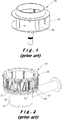
- FIGS 1-3 respectively show a prior art impeller 30 and cutting head 20.
- the impeller 30 has a bottom plate 35 which is releasably fixed to a drive shaft of a prior art cutting apparatus for rotation inside the cutting head 20.
- the cutting head 20 is a cylindrical assembly comprising a top ring 26, a bottom ring 29 and a plurality of cutting stations 27 held between these rings, each comprising one cutting element 28. The assembly is held together by a number of bolts and fixed to the frame base 10 of the machine.
- the cutting stations 27 are tiltable for adjusting the gap between the cutting element 28 and an opposite part at the rear of the subsequent cutting station, i.e. for adjusting the thickness of the part which is cut off.
- the top sides of the cutting head 20 and impeller 30 are open.
- product to be cut is supplied into the cutting head from this open top side, lands on the bottom plate 35 of the impeller and is moved towards the cutting elements 28 firstly by centrifugal force, which is imparted to the product by the rotation of the impeller 30, and secondly by the paddles 34 of the impeller.
- the cutting head 20 is stationary.
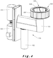
- the cutting apparatus shown in figures 4-8 is a first embodiment of a cutting apparatus according to the invention. It comprises a base 100 which carries a rotatable cutting head 200 and an impeller 300, adapted for rotating concentrically within the cutting head.
- a first drive mechanism which is constituted by a first drive shaft 301, drive belt 302 and motor 303, is provided for driving the rotation of the impeller 300.
- a second drive mechanism which is constituted by a second drive shaft 201, drive belt 202 and motor 203, is provided for driving the rotation of the cutting head.
- the first and second drive shafts are concentrical.
- the second drive shaft 201 which drives the cutting head 200 is rotatably mounted by means of bearings 104, 105 inside a stationary outer bearing housing 103, which forms part of the base 100.
- the first drive shaft 301 which drives the impeller is rotatably mounted by means of bearings 106, 107 inside the first drive shaft 201.
- these bearings 104-107 are tapered roller bearings, slanting in opposite directions, which is preferred in view of withstanding the forces which occur during operation of the apparatus.
- angular contact bearings could be used, or any other bearings deemed suitable by the person skilled in the art.
- the base 100 comprises an arm 101, which is rotatably mounted on a post 102, so that the cutting head 200 and impeller 300 can be rotated away from the cutting position for cleaning, maintenance, replacement etc.
- FIGS 6-8 respectively show the impeller 300 and cutting head 200 fitted on the apparatus of figures 4-5 .
- the impeller 300 is releasably fixed to the first drive shaft 301 for rotation inside the cutting head 200.
- the cutting head 200 is a cylindrical assembly comprising a top ring 206, a bottom plate 205 and a plurality of cutting stations 207 held between these two parts, each comprising one cutting element 208.
- the assembly is held together by a number of bolts and releasably fixed to the second drive shaft 201.
- the cutting stations 207 are tiltable for adjusting the gap between the cutting element 208 and an opposite part at the rear of the subsequent cutting station, i.e. for adjusting the thickness of the part which is cut off.
- the top sides of the cutting head 200 and impeller 300 are open.
- product to be cut is supplied into the cutting head from this open top side, lands on the bottom plate 305 of the impeller and is moved towards the cutting elements 208 firstly by centrifugal force, which is imparted to the product by the rotation of the impeller 300, and secondly by the paddles 304 of the impeller.
- the cutting head 200 is fitted with cutting elements 208, for example blades which make straight cuts in the product, for example to make potato chips.
- cutting elements 208 for example blades which make straight cuts in the product, for example to make potato chips.
- corrugated cutting elements could be fitted in order to make for example crinkle cut potato chips or shreds.
- FIG 9 shows an alternative embodiment of a cutting head 400 with an adapted impeller 410 which is also capable of being used on the apparatus of figures 4-5 .
- the cutting head and impeller again are both rotatable and are driven by means of concentrical shafts in the same way as described above.
- the cutting stations 401 in this embodiment comprise each a larger blade 402 and a number of smaller, so-called julienne tabs 403 extending at an angle thereto, in particular substantially perpendicular thereto.
- the julienne tabs 403 are welded onto the larger blades 402, but they could also be removably fixed thereto.
- the julienne tabs 403 are fixed to and extend perpendicular to the bevel of the larger blades 402, but they could also be fixed to the larger blades 402 behind the bevel.
- the front cutting edges of the julienne tabs 403 are slightly behind the front cutting edge of the larger blade 402, all at the same distance. Alternatively, they could also be located at varying distances from the front cutting edge of the larger blade 402, for example in a staggered or alternating configuration.
- the julienne tabs 403 are stabilised by means of slots 404 in the subsequent cutting station, so that during operation stresses can be relieved and the desired cut can be better maintained.
- the slots 404 extend a given distance into the rear end of the cutting stations 401 to accommodate for the variable positions of the julienne tabs 403 upon pivoting the cutting stations 401 for varying the gap.
- this cutting head 400 the product is cut in two directions at once. It can for example be used to cut French fries from potatoes or to cut lettuce.
- cutting stations can be used with cutting edges for milling or comminuting products (e.g. salt, spices) or viscous liquids (e.g. butters, spreads).
- products e.g. salt, spices
- viscous liquids e.g. butters, spreads.
- the apparatus can also be used for manufacturing pharmaceutical products like for example ointments.
- cutting stations can be used with grating surfaces for making grated cheese, or with any other cutting elements known to the person skilled in the art.
- the cutting apparatus of figures 4-5 can even be used with the prior art cutting head and impeller of figures 1-3 .
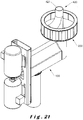
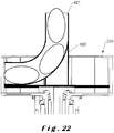
- FIGs 21 and 22 show an alternative embodiment of an impeller 420 which can be used on the apparatus of figures 4-5 with the same cutting head 200.
- the impeller 420 comprises a feed tube 421 which starts vertically in the centre of the impeller and bends towards the cutting head 200.
- This impeller 420 is intended for products for which it is desired to feed them towards the cutting head 200 in a directed way, such as, for example, products with an elongated shape of which it is desired their shorter sides face the cutting elements 208 and they are cut into chips having a more circular shape.
- the mouth of the feed tube can also be oriented at an angle with respect to the cutting elements 208, so that the products are cut into chips having a more oval shape.
- the impeller 420 is for example highly suitable for cutting larger, elongated potatoes into circular chips or for cutting onions into onion rings.
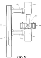
- the cutting apparatus shown in figures 10-14 has many features in common with the cutting apparatus shown in figures 4-5 . As a result, only the differences will be explained in detail.
- the cutting apparatus shown in figures 10-14 is mainly different in the driving mechanisms used to drive the impeller 500 and the cutting head 600.
- an in line drive mechanism is used, i.e. the impeller 500 is directly fixed to the shaft of the motor 503 and the cutting head 600 is directly fixed to the shaft of the motor 603.
- This has the advantage that any intermediate drive components, such as the driving belts 202, 302 and the concentric shafts 201, 202 of the apparatus of figures 4-5 are avoided, which simplifies the construction.
- the concentric rotation of the impeller 500 inside the cutting head 600 is stabilised by means of a spring-loaded pin 501 which fits into a tapered hole 601 in the centre of the cutting head 600.
- the cutting head 600 is in this embodiment an assembly of a top ring 606, cutting stations 607 and a spider support 609 at the bottom.
- the cutting stations 607 are held between the top ring 606 and the spider support 609 like in the above described embodiment.
- the spider support 609 is used instead of a full bottom plate in order to save weight.
- the spider support can be connected to the shaft of the motor 603 by means of notches which are engaged by pins on the shaft. This can be a quick release engagement which can be fixed/loosened by for example turning the spider support 609 over +57-5° with respect to the motor shaft.
- the spider support 609 could also be bolted to the motor shaft, or releasably fixed by any other means known to the person skilled in the art.
- the base 110 comprises a vertical post 111 with a fixed top arm 112 on which the impeller motor 503 is mounted with the shaft pointing downwards.
- the cutting head motor 603 is mounted on the post 111 with the shaft pointing upwards by means of a vertically movable and horizontally rotatable arm 113.
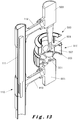
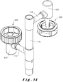
- the cutting head 600 can be removed from the impeller 500 for maintenance, replacement, etc. by subsequently moving the arm 113 downwards ( fig. 13 ) and rotating it in a horizontal plane ( fig. 14 ).
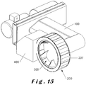
- the cutting apparatus shown in figure 15 is the same as the one of figures 4-5 , but the cutting head 200 and the impeller 300 are oriented for rotation around a horizontal axis and are mounted adjacent a dicing unit 430.
- the cutting head 200 can here be locked to the base 100 by means of a releasable locking mechanism (not shown) to make it stationary.
- the cutting stations 207 can all be tilted to a non-cutting position (zero gap) except for the one located at the dicing unit 430.
- a dicing unit is otherwise known in the art and therefore needs no further description here. So in this embodiment, the apparatus is convertible between a first mode of operation, namely with a stationary cutting head adjacent a dicing unit, and a second mode of operation with a rotating cutting head.
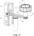
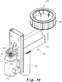
- the cutting apparatus shown in figure 16 is similar to that of figures 4-5 in that it has the same cutting head 200 and impeller 300 with concentrical drive shafts, mounted on a base 100 comprising an arm 101 which is rotatably mounted on a post 102.
- the drive mechanisms for the cutting head and the impeller are however different in the aspect that they comprise a shared motor 120 with two shafts: a first shaft 121 running the drive belt 302 for the impeller 300 and a second shaft 122 running the drive belt 202 for the cutting head 200.
- These shafts 121, 122 are internally coupled to each other by means of a gear mechanism which sets a predetermined ratio of the rotational speeds of the shafts and the rotational relationship, i.e. whether the cutting head and the impeller rotate in the same direction or not. So in this embodiment there is a fixed ratio between the first rotational speed of the impeller 300 and the second rotational speed of the cutting head 200, which means that this apparatus is configured for always cutting the same product or at least products for which the fixed ratio is optimal.
- the cutting apparatus shown in figure 17 is similar to that of figures 4-5 in that it has the same cutting head 200 and impeller 300 with concentrical drive shafts, mounted on a top part 131 of a base 130 which is tiltably fixed on a vertical post 132. In this way, the top part 131 carrying the cutting head 200 and impeller 300 can be tilted as a whole, so that the angle at which the cutting head 200 and the impeller 300 rotate is adaptable to the situation.
- the cutting elements 208 of the cutting head 200 are oriented to impart cutting action in counterclockwise direction, i.e. the cutting elements cut through the product in counterclockwise direction or, alternatively stated, the product passes the cutting elements in clockwise direction.
- This is the mode of operation which is used in the art (with stationary cutting heads), but it is evident that the orientation of the cutting elements can be turned around to impart cutting action in clockwise direction.
- the arrows V CH and V IMP on these figures respectively represent the rotational speed of the cutting head and the rotational speed of the impeller.
- the impeller 300 and the cutting head 200 rotate in the same direction, namely both clockwise. They rotate at different rotational speeds, i.e. the cutting head is not stationary with respect to the impeller.
- the first rotational speed V IMP of the impeller 300 is greater than the second rotational speed V CH of the cutting head 200, so that the paddles 304 of the impeller move the product towards the cutting elements 208.
- the first rotational speed of the impeller 300 sets the centrifugal force exerted on the product, i.e. the force with which the product is pressed against the interior of the cutting stations 207.
- the difference in rotational speed sets the cutting velocity with which the cutting elements 208 cut through the product, which is pushed towards them by means of the paddles of the impeller 304.
- the impeller 300 and the cutting head 200 rotate in opposite directions, namely the impeller 300 rotates clockwise and the cutting head 200 rotates counterclockwise.
- the first and second rotational speeds V IMP and V CH can be equal or different in absolute value.
- the first rotational speed V IMP of the impeller 300 sets the centrifugal force.
- the cutting velocity is related to the sum of the absolute values of the rotational speeds V CH and V IMP , as their direction is opposite.
- the impeller 300 and the cutting head 200 rotate in the same direction, namely both counterclockwise, with the impeller 300 at a smaller rotational speed than the cutting head 200.
- the first rotational speed V IMP of the impeller 300 sets the centrifugal force.
- the cutting elements 208 move towards the paddles 304, so towards the product to be cut.
- the cutting velocity is determined by the difference between the first and second rotational speeds.
- Table 1 shows the relationship between the impeller rotational speed for a 178 mm radius and the centrifugal force experienced by potatoes of different weights.
- the cetrifugal acceleration (g-force) is 131.95 m/s 2 ( ⁇ 13 g) which corresponds to the centrifugal forces in the second column for the weights given in the first column;
- the cetrifugal acceleration (g-force) is 103.26 m/s 2 ( ⁇ 10 g) which corresponds to the centrifugal forces in the third column for the weights given in the first column.
- the cutting velocity is preferably in the range of 3 to 4.8 m/s, more preferably in the lower half of this range.
- the cutting velocity is preferably in the range of .3 to 5.5 m/s.
- the centrifugal force can be reduced with respect to the prior art with a stationary cutting head.
- the impeller when cutting cheese products the impeller is rotated at a relatively high speed (e.g. 400 RPM) in order to obtain the desired cutting velocity, but at such speeds the cheese products may be undesirably compressed against the interior of the cutting head.
- the cheese product needed to be cooled to a temperature of -4°C to harden the product and avoid compression.
- the centrifugal force can be reduced and the cutting velocity set independently therefrom, so that the cutting operation can occur at higher temperatures, i.e. temperatures of -3°C or above, e.g. at 10°C, reducing the extent of cooling needed prior to cutting.
- Examples of other products which can be cut in a more advantageous way with the apparatus and method of the invention are nut products, e.g. almonds, peanuts (e.g. to manufacture peanut butter) or other nuts; root products, e.g. ginger, garlic, or other; and also other products such as e.g. orange peel.
- nut products e.g. almonds, peanuts (e.g. to manufacture peanut butter) or other nuts
- root products e.g. ginger, garlic, or other
- other products such as e.g. orange peel.
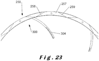
- FIG 23 shows a further alternative embodiment of a cutting head 250 which can be used on apparatuses according to the invention, for example together with the same impeller 300 described above.
- the cutting head 250 comprises cutting stations 257 which have cutting elements 258, 259 at both ends. These cutting stations 257 are tiltable for setting the gap and also for setting the direction in which the cutting head cuts, i.e. in clockwise or counterclockwise directions. In other words, this cutting head 257 is capable of cutting products by rotation in either direction, provided that the cutting stations are correctly set.
- the impeller drive shaft could also be made hollow, for example for accommodating a large bolt with which the impeller is fixed to the impeller drive shaft, or for connecting a liquid supply and supplying a liquid (e.g. water) to the cutting head from the bottom side through the impeller drive shaft, or both, in which case the bolt would also be hollow.
- a liquid e.g. water
Landscapes
- Life Sciences & Earth Sciences (AREA)
- Forests & Forestry (AREA)
- Engineering & Computer Science (AREA)
- Mechanical Engineering (AREA)
- Food-Manufacturing Devices (AREA)
- Crushing And Pulverization Processes (AREA)
- Finish Polishing, Edge Sharpening, And Grinding By Specific Grinding Devices (AREA)
- Apparatuses For Bulk Treatment Of Fruits And Vegetables And Apparatuses For Preparing Feeds (AREA)
- Preparation Of Fruits And Vegetables (AREA)
Applications Claiming Priority (3)
| Application Number | Priority Date | Filing Date | Title |
|---|---|---|---|
| US201161473826P | 2011-04-11 | 2011-04-11 | |
| BE2011/0295A BE1019977A3 (nl) | 2011-04-11 | 2011-05-16 | Inrichting en werkwijze voor het snijden van producten. |
| PCT/EP2012/056401 WO2012139988A1 (en) | 2011-04-11 | 2012-04-10 | Apparatus and method for cutting products |
Publications (2)
| Publication Number | Publication Date |
|---|---|
| EP2697019A1 EP2697019A1 (en) | 2014-02-19 |
| EP2697019B1 true EP2697019B1 (en) | 2020-07-08 |
Family
ID=47008846
Family Applications (2)
| Application Number | Title | Priority Date | Filing Date |
|---|---|---|---|
| EP12719608.7A Active EP2697019B1 (en) | 2011-04-11 | 2012-04-10 | Apparatus and method for cutting products |
| EP12719609.5A Active EP2697020B1 (en) | 2011-04-11 | 2012-04-10 | Apparatus and method for cutting products |
Family Applications After (1)
| Application Number | Title | Priority Date | Filing Date |
|---|---|---|---|
| EP12719609.5A Active EP2697020B1 (en) | 2011-04-11 | 2012-04-10 | Apparatus and method for cutting products |
Country Status (15)
| Country | Link |
|---|---|
| US (3) | US10427314B2 (https=) |
| EP (2) | EP2697019B1 (https=) |
| JP (1) | JP6053753B2 (https=) |
| KR (1) | KR102013794B1 (https=) |
| CN (1) | CN103459105B (https=) |
| AU (1) | AU2012241950B2 (https=) |
| BE (1) | BE1019977A3 (https=) |
| BR (1) | BR112013025857B1 (https=) |
| CA (1) | CA2833065C (https=) |
| ES (2) | ES2809874T3 (https=) |
| MX (1) | MX339250B (https=) |
| PL (1) | PL2697020T3 (https=) |
| RU (1) | RU2606138C2 (https=) |
| WO (2) | WO2012139991A1 (https=) |
| ZA (1) | ZA201308237B (https=) |
Families Citing this family (24)
| Publication number | Priority date | Publication date | Assignee | Title |
|---|---|---|---|---|
| US9855668B2 (en) | 2011-04-11 | 2018-01-02 | Fam | System for cutting products, controller therefor, method for cutting products and computer program product implementing same |
| BE1022743B1 (nl) | 2013-11-21 | 2016-08-26 | Fam | Messamenstel voor vlak meslemmet en hiermee uitgerust snijsysteem |
| ES2813375T3 (es) | 2014-03-10 | 2021-03-23 | Fam | Conjunto de cabezal de corte para un aparato de corte centrífugo y aparato centrífugo equipado con este |
| BR112017019808A2 (pt) * | 2015-03-19 | 2018-05-29 | K S Premier Products Co Ltd | máquina para cortar mandioca |
| ES2930454T3 (es) | 2015-06-12 | 2022-12-13 | Urschel Laboratories Inc | Máquinas y métodos para el corte de productos |
| SG11201803233QA (en) * | 2015-10-19 | 2018-05-30 | Olanrewaju Aluko | Device and method for peeling beans |
| CN106313164B (zh) * | 2016-09-06 | 2018-06-12 | 河海大学常州校区 | 切菜机装置及切菜方法 |
| US11052561B2 (en) | 2017-06-30 | 2021-07-06 | J.R. Simplot Company | Cut food denester |
| ES2833923T3 (es) | 2017-12-04 | 2021-06-16 | Fam | Rodete, aparato de corte centrífugo que lo comprende y su método de funcionamiento |
| CN208388721U (zh) * | 2017-12-08 | 2019-01-18 | 宁波希佳电器有限公司 | 一种能吸脚皮灰尘的磨脚器 |
| EP3527342A1 (en) | 2018-02-20 | 2019-08-21 | Fam | Knife assembly and cutting system equipped with same |
| US11606911B2 (en) * | 2018-03-27 | 2023-03-21 | Eteros Technologies Usa, Inc. | Plant material trimming device |
| CN112674360B (zh) * | 2020-12-12 | 2021-12-28 | 临泉县超杰蔬菜脱水有限公司 | 一种集清洗分选分切为一体的蒜瓣加工设备 |
| CN112604969B (zh) * | 2020-12-12 | 2021-12-24 | 临泉县超杰蔬菜脱水有限公司 | 一种蒜瓣清洗后自动分选及多工位切割加工工艺 |
| USD1022327S1 (en) | 2020-12-23 | 2024-04-09 | International Edge, Inc. | Foot file |
| USD1017136S1 (en) | 2020-12-23 | 2024-03-05 | Telebrands Corp. | Abrasive skin treatment device |
| USD1005504S1 (en) | 2020-12-23 | 2023-11-21 | Telebrands Corp. | Abrasive skin treatment device |
| US12128579B2 (en) * | 2021-02-12 | 2024-10-29 | Urschel Laboratories, Inc. | Impellers for cutting machines and cutting machines equipped therewith |
| USD969449S1 (en) | 2021-03-29 | 2022-11-15 | Urschel Laboratories, Inc. | Food product |
| USD1023468S1 (en) | 2021-03-29 | 2024-04-16 | Telebrands Corp. | Foot file |
| USD979178S1 (en) | 2021-03-29 | 2023-02-28 | Urschel Laboratories, Inc. | Food product |
| USD969570S1 (en) | 2021-03-29 | 2022-11-15 | Urschel Laboratories, Inc. | Knife |
| EP4215321B1 (en) * | 2022-01-25 | 2024-12-18 | The Procter & Gamble Company | Apparatus and method for cutting a substrate |
| CN114770624A (zh) * | 2022-04-29 | 2022-07-22 | 青岛精诚旺电子设备有限公司 | 一种旋转切切管机 |
Family Cites Families (27)
| Publication number | Priority date | Publication date | Assignee | Title |
|---|---|---|---|---|
| US3123114A (en) * | 1964-03-03 | Richard a | ||
| US2660208A (en) | 1950-03-11 | 1953-11-24 | Williams | Pitting structure |
| US2859784A (en) * | 1956-10-23 | 1958-11-11 | F B Pease Company | Potato slicing machine |
| JPS4510592Y1 (https=) | 1966-12-06 | 1970-05-14 | ||
| DE2651568C3 (de) * | 1976-11-12 | 1979-04-05 | Gerdes Gmbh & Co, 5830 Schwelm | Schneidvorrichtung zum Zerkleinern von Gartenfrüchten, sogenannter Zwiebelschneider |
| SE425953B (sv) * | 1979-03-27 | 1982-11-29 | Berggren Torsten L | Maskin for framstellning av span ur flis |
| US4406603A (en) * | 1982-04-16 | 1983-09-27 | Cuisinarts Research & Development, Inc. | Pasta extruder apparatus for attachment to a food processor or similar appliance |
| JPS60153796U (ja) * | 1984-03-23 | 1985-10-14 | カルビ−株式会社 | 食品材料用カツタ |
| US4648296A (en) | 1984-11-26 | 1987-03-10 | Frito-Lay Inc. | Method and apparatus for feeding slicers |
| US4604925A (en) * | 1985-05-24 | 1986-08-12 | Frito-Lay, Inc. | Method and apparatus for slicing produce |
| US4796818A (en) * | 1987-07-30 | 1989-01-10 | Beloit Corporation | Chip slicer improvement |
| US4972888A (en) * | 1989-11-14 | 1990-11-27 | Acrowood Corporation | Blade-carrying drum assembly for chip slicing machines |
| JP3049084B2 (ja) | 1990-11-20 | 2000-06-05 | ヒート アンド コントロール インコーポレーテッド | バッチフライド食品の調理方法及び装置 |
| US5694824A (en) * | 1994-04-18 | 1997-12-09 | Urschel Laboratories Incorporated | Cutting head for slicing a food product |
| FR2735412B1 (fr) * | 1995-06-19 | 1997-08-22 | Unir Ultra Propre Nutrition In | Dispositif de decoupage par ultrasons |
| DE50004302D1 (de) * | 1999-02-11 | 2003-12-11 | Bucher Guyer Ag Masch | Vorrichtung zum zerreissen von früchten |
| DE19914707A1 (de) * | 1999-03-31 | 2000-10-05 | Biforce Anstalt Vaduz | Verfahren und Vorrichtung zum Aufschneiden von Lebensmittelprodukten |
| JP4183363B2 (ja) | 2000-03-30 | 2008-11-19 | 三洋電機株式会社 | 太陽電池モジュールの製造方法 |
| US6536691B2 (en) * | 2001-02-23 | 2003-03-25 | Leprino Foods Company | Apparatus for and method of shredding a product |
| WO2004106015A2 (en) | 2003-05-29 | 2004-12-09 | Urschel Laboratories, Inc. | Cutting head for cutting a food product |
| RU39296U1 (ru) * | 2004-03-19 | 2004-07-27 | Погосян Юрий Гургенович | Устройство для измельчения продуктов |
| ATE365611T1 (de) * | 2004-04-09 | 2007-07-15 | Fam | Schneidrad zum schneiden von nahrungsmitteln |
| KR100770641B1 (ko) * | 2006-05-26 | 2007-10-30 | 김홍배 | 간접 가열 방식의 조리 장치 |
| CN201613557U (zh) * | 2009-10-13 | 2010-10-27 | 盐城市坤鹏机械厂 | 电脑控制全自动捆条机 |
| US8408108B2 (en) * | 2010-02-12 | 2013-04-02 | Kraft Foods Group Brands Llc | Systems and methods for slicing food products |
| CN201603903U (zh) * | 2010-03-09 | 2010-10-13 | 成都市猎户座科技有限责任公司 | 一种plc控制坡口机 |
| CN101961874B (zh) * | 2010-09-19 | 2012-12-19 | 哈尔滨工业大学 | 一种基于plc控制的全自动试样切割机及其切割方法 |
-
2011
- 2011-05-16 BE BE2011/0295A patent/BE1019977A3/nl active
-
2012
- 2012-04-10 US US14/111,410 patent/US10427314B2/en active Active
- 2012-04-10 US US14/111,443 patent/US9643332B2/en active Active
- 2012-04-10 RU RU2013148635A patent/RU2606138C2/ru active
- 2012-04-10 CN CN201280017591.2A patent/CN103459105B/zh active Active
- 2012-04-10 ES ES12719609T patent/ES2809874T3/es active Active
- 2012-04-10 EP EP12719608.7A patent/EP2697019B1/en active Active
- 2012-04-10 JP JP2014504271A patent/JP6053753B2/ja active Active
- 2012-04-10 CA CA2833065A patent/CA2833065C/en active Active
- 2012-04-10 WO PCT/EP2012/056404 patent/WO2012139991A1/en not_active Ceased
- 2012-04-10 EP EP12719609.5A patent/EP2697020B1/en active Active
- 2012-04-10 PL PL12719609T patent/PL2697020T3/pl unknown
- 2012-04-10 ES ES12719608T patent/ES2817884T3/es active Active
- 2012-04-10 BR BR112013025857-8A patent/BR112013025857B1/pt not_active IP Right Cessation
- 2012-04-10 KR KR1020137029253A patent/KR102013794B1/ko active Active
- 2012-04-10 MX MX2013011844A patent/MX339250B/es active IP Right Grant
- 2012-04-10 AU AU2012241950A patent/AU2012241950B2/en active Active
- 2012-04-10 WO PCT/EP2012/056401 patent/WO2012139988A1/en not_active Ceased
-
2013
- 2013-11-04 ZA ZA2013/08237A patent/ZA201308237B/en unknown
-
2016
- 2016-12-28 US US15/393,124 patent/US10213935B2/en active Active
Non-Patent Citations (1)
| Title |
|---|
| None * |
Also Published As
| Publication number | Publication date |
|---|---|
| KR20140022865A (ko) | 2014-02-25 |
| MX2013011844A (es) | 2014-02-11 |
| PL2697020T3 (pl) | 2021-04-06 |
| US20140030396A1 (en) | 2014-01-30 |
| BR112013025857A2 (pt) | 2020-06-02 |
| US9643332B2 (en) | 2017-05-09 |
| CN103459105A (zh) | 2013-12-18 |
| RU2013148635A (ru) | 2015-05-20 |
| JP6053753B2 (ja) | 2016-12-27 |
| EP2697020A1 (en) | 2014-02-19 |
| WO2012139991A1 (en) | 2012-10-18 |
| US10213935B2 (en) | 2019-02-26 |
| MX339250B (es) | 2016-05-17 |
| ES2817884T3 (es) | 2021-04-08 |
| CA2833065C (en) | 2019-02-26 |
| US10427314B2 (en) | 2019-10-01 |
| EP2697019A1 (en) | 2014-02-19 |
| ES2809874T3 (es) | 2021-03-08 |
| CA2833065A1 (en) | 2012-10-18 |
| US20140083266A1 (en) | 2014-03-27 |
| US20170106556A1 (en) | 2017-04-20 |
| EP2697020B1 (en) | 2020-05-20 |
| BE1019977A3 (nl) | 2013-03-05 |
| RU2606138C2 (ru) | 2017-01-10 |
| AU2012241950A1 (en) | 2013-10-17 |
| BR112013025857B1 (pt) | 2021-04-20 |
| CN103459105B (zh) | 2017-04-12 |
| JP2014511773A (ja) | 2014-05-19 |
| AU2012241950B2 (en) | 2017-01-19 |
| KR102013794B1 (ko) | 2019-08-23 |
| ZA201308237B (en) | 2014-06-25 |
| WO2012139988A1 (en) | 2012-10-18 |
Similar Documents
| Publication | Publication Date | Title |
|---|---|---|
| EP2697019B1 (en) | Apparatus and method for cutting products | |
| EP3307499B1 (en) | Machines and methods for cutting products | |
| US9855668B2 (en) | System for cutting products, controller therefor, method for cutting products and computer program product implementing same | |
| EP2760648B1 (en) | Impeller for centrifugal food cutting apparatus and centrifugal food cutting apparatus comprising same | |
| EP2760649B1 (en) | Cutting head assembly for centrifugal cutting apparatus and centrifugal apparatus equipped with same | |
| HUE033320T2 (en) | Crusher for crushing the product | |
| EP3116694B1 (en) | Dicing machines and methods of use | |
| CN210791178U (zh) | 一种v型皮带切菜机 | |
| US11273571B2 (en) | Cutting head assembly for centrifugal cutting apparatus and centrifugal apparatus equipped |
Legal Events
| Date | Code | Title | Description |
|---|---|---|---|
| PUAI | Public reference made under article 153(3) epc to a published international application that has entered the european phase |
Free format text: ORIGINAL CODE: 0009012 |
|
| 17P | Request for examination filed |
Effective date: 20131021 |
|
| AK | Designated contracting states |
Kind code of ref document: A1 Designated state(s): AL AT BE BG CH CY CZ DE DK EE ES FI FR GB GR HR HU IE IS IT LI LT LU LV MC MK MT NL NO PL PT RO RS SE SI SK SM TR |
|
| DAX | Request for extension of the european patent (deleted) | ||
| STAA | Information on the status of an ep patent application or granted ep patent |
Free format text: STATUS: EXAMINATION IS IN PROGRESS |
|
| 17Q | First examination report despatched |
Effective date: 20180912 |
|
| GRAP | Despatch of communication of intention to grant a patent |
Free format text: ORIGINAL CODE: EPIDOSNIGR1 |
|
| STAA | Information on the status of an ep patent application or granted ep patent |
Free format text: STATUS: GRANT OF PATENT IS INTENDED |
|
| INTG | Intention to grant announced |
Effective date: 20190510 |
|
| GRAJ | Information related to disapproval of communication of intention to grant by the applicant or resumption of examination proceedings by the epo deleted |
Free format text: ORIGINAL CODE: EPIDOSDIGR1 |
|
| STAA | Information on the status of an ep patent application or granted ep patent |
Free format text: STATUS: EXAMINATION IS IN PROGRESS |
|
| INTC | Intention to grant announced (deleted) | ||
| GRAP | Despatch of communication of intention to grant a patent |
Free format text: ORIGINAL CODE: EPIDOSNIGR1 |
|
| STAA | Information on the status of an ep patent application or granted ep patent |
Free format text: STATUS: GRANT OF PATENT IS INTENDED |
|
| INTG | Intention to grant announced |
Effective date: 20200226 |
|
| GRAS | Grant fee paid |
Free format text: ORIGINAL CODE: EPIDOSNIGR3 |
|
| GRAA | (expected) grant |
Free format text: ORIGINAL CODE: 0009210 |
|
| STAA | Information on the status of an ep patent application or granted ep patent |
Free format text: STATUS: THE PATENT HAS BEEN GRANTED |
|
| AK | Designated contracting states |
Kind code of ref document: B1 Designated state(s): AL AT BE BG CH CY CZ DE DK EE ES FI FR GB GR HR HU IE IS IT LI LT LU LV MC MK MT NL NO PL PT RO RS SE SI SK SM TR |
|
| REG | Reference to a national code |
Ref country code: GB Ref legal event code: FG4D |
|
| REG | Reference to a national code |
Ref country code: CH Ref legal event code: EP Ref country code: AT Ref legal event code: REF Ref document number: 1287959 Country of ref document: AT Kind code of ref document: T Effective date: 20200715 |
|
| REG | Reference to a national code |
Ref country code: DE Ref legal event code: R096 Ref document number: 602012071125 Country of ref document: DE |
|
| REG | Reference to a national code |
Ref country code: IE Ref legal event code: FG4D |
|
| REG | Reference to a national code |
Ref country code: SE Ref legal event code: TRGR |
|
| REG | Reference to a national code |
Ref country code: NL Ref legal event code: FP |
|
| REG | Reference to a national code |
Ref country code: LT Ref legal event code: MG4D |
|
| REG | Reference to a national code |
Ref country code: AT Ref legal event code: MK05 Ref document number: 1287959 Country of ref document: AT Kind code of ref document: T Effective date: 20200708 |
|
| PG25 | Lapsed in a contracting state [announced via postgrant information from national office to epo] |
Ref country code: FI Free format text: LAPSE BECAUSE OF FAILURE TO SUBMIT A TRANSLATION OF THE DESCRIPTION OR TO PAY THE FEE WITHIN THE PRESCRIBED TIME-LIMIT Effective date: 20200708 Ref country code: HR Free format text: LAPSE BECAUSE OF FAILURE TO SUBMIT A TRANSLATION OF THE DESCRIPTION OR TO PAY THE FEE WITHIN THE PRESCRIBED TIME-LIMIT Effective date: 20200708 Ref country code: LT Free format text: LAPSE BECAUSE OF FAILURE TO SUBMIT A TRANSLATION OF THE DESCRIPTION OR TO PAY THE FEE WITHIN THE PRESCRIBED TIME-LIMIT Effective date: 20200708 Ref country code: GR Free format text: LAPSE BECAUSE OF FAILURE TO SUBMIT A TRANSLATION OF THE DESCRIPTION OR TO PAY THE FEE WITHIN THE PRESCRIBED TIME-LIMIT Effective date: 20201009 Ref country code: PT Free format text: LAPSE BECAUSE OF FAILURE TO SUBMIT A TRANSLATION OF THE DESCRIPTION OR TO PAY THE FEE WITHIN THE PRESCRIBED TIME-LIMIT Effective date: 20201109 Ref country code: BG Free format text: LAPSE BECAUSE OF FAILURE TO SUBMIT A TRANSLATION OF THE DESCRIPTION OR TO PAY THE FEE WITHIN THE PRESCRIBED TIME-LIMIT Effective date: 20201008 Ref country code: AT Free format text: LAPSE BECAUSE OF FAILURE TO SUBMIT A TRANSLATION OF THE DESCRIPTION OR TO PAY THE FEE WITHIN THE PRESCRIBED TIME-LIMIT Effective date: 20200708 Ref country code: NO Free format text: LAPSE BECAUSE OF FAILURE TO SUBMIT A TRANSLATION OF THE DESCRIPTION OR TO PAY THE FEE WITHIN THE PRESCRIBED TIME-LIMIT Effective date: 20201008 |
|
| PG25 | Lapsed in a contracting state [announced via postgrant information from national office to epo] |
Ref country code: RS Free format text: LAPSE BECAUSE OF FAILURE TO SUBMIT A TRANSLATION OF THE DESCRIPTION OR TO PAY THE FEE WITHIN THE PRESCRIBED TIME-LIMIT Effective date: 20200708 Ref country code: LV Free format text: LAPSE BECAUSE OF FAILURE TO SUBMIT A TRANSLATION OF THE DESCRIPTION OR TO PAY THE FEE WITHIN THE PRESCRIBED TIME-LIMIT Effective date: 20200708 Ref country code: PL Free format text: LAPSE BECAUSE OF FAILURE TO SUBMIT A TRANSLATION OF THE DESCRIPTION OR TO PAY THE FEE WITHIN THE PRESCRIBED TIME-LIMIT Effective date: 20200708 Ref country code: IS Free format text: LAPSE BECAUSE OF FAILURE TO SUBMIT A TRANSLATION OF THE DESCRIPTION OR TO PAY THE FEE WITHIN THE PRESCRIBED TIME-LIMIT Effective date: 20201108 |
|
| REG | Reference to a national code |
Ref country code: ES Ref legal event code: FG2A Ref document number: 2817884 Country of ref document: ES Kind code of ref document: T3 Effective date: 20210408 |
|
| REG | Reference to a national code |
Ref country code: DE Ref legal event code: R097 Ref document number: 602012071125 Country of ref document: DE |
|
| PG25 | Lapsed in a contracting state [announced via postgrant information from national office to epo] |
Ref country code: SM Free format text: LAPSE BECAUSE OF FAILURE TO SUBMIT A TRANSLATION OF THE DESCRIPTION OR TO PAY THE FEE WITHIN THE PRESCRIBED TIME-LIMIT Effective date: 20200708 Ref country code: RO Free format text: LAPSE BECAUSE OF FAILURE TO SUBMIT A TRANSLATION OF THE DESCRIPTION OR TO PAY THE FEE WITHIN THE PRESCRIBED TIME-LIMIT Effective date: 20200708 Ref country code: CZ Free format text: LAPSE BECAUSE OF FAILURE TO SUBMIT A TRANSLATION OF THE DESCRIPTION OR TO PAY THE FEE WITHIN THE PRESCRIBED TIME-LIMIT Effective date: 20200708 Ref country code: DK Free format text: LAPSE BECAUSE OF FAILURE TO SUBMIT A TRANSLATION OF THE DESCRIPTION OR TO PAY THE FEE WITHIN THE PRESCRIBED TIME-LIMIT Effective date: 20200708 Ref country code: EE Free format text: LAPSE BECAUSE OF FAILURE TO SUBMIT A TRANSLATION OF THE DESCRIPTION OR TO PAY THE FEE WITHIN THE PRESCRIBED TIME-LIMIT Effective date: 20200708 |
|
| PLBE | No opposition filed within time limit |
Free format text: ORIGINAL CODE: 0009261 |
|
| STAA | Information on the status of an ep patent application or granted ep patent |
Free format text: STATUS: NO OPPOSITION FILED WITHIN TIME LIMIT |
|
| PG25 | Lapsed in a contracting state [announced via postgrant information from national office to epo] |
Ref country code: AL Free format text: LAPSE BECAUSE OF FAILURE TO SUBMIT A TRANSLATION OF THE DESCRIPTION OR TO PAY THE FEE WITHIN THE PRESCRIBED TIME-LIMIT Effective date: 20200708 |
|
| 26N | No opposition filed |
Effective date: 20210409 |
|
| PG25 | Lapsed in a contracting state [announced via postgrant information from national office to epo] |
Ref country code: SK Free format text: LAPSE BECAUSE OF FAILURE TO SUBMIT A TRANSLATION OF THE DESCRIPTION OR TO PAY THE FEE WITHIN THE PRESCRIBED TIME-LIMIT Effective date: 20200708 |
|
| PG25 | Lapsed in a contracting state [announced via postgrant information from national office to epo] |
Ref country code: SI Free format text: LAPSE BECAUSE OF FAILURE TO SUBMIT A TRANSLATION OF THE DESCRIPTION OR TO PAY THE FEE WITHIN THE PRESCRIBED TIME-LIMIT Effective date: 20200708 |
|
| PG25 | Lapsed in a contracting state [announced via postgrant information from national office to epo] |
Ref country code: MC Free format text: LAPSE BECAUSE OF FAILURE TO SUBMIT A TRANSLATION OF THE DESCRIPTION OR TO PAY THE FEE WITHIN THE PRESCRIBED TIME-LIMIT Effective date: 20200708 |
|
| PG25 | Lapsed in a contracting state [announced via postgrant information from national office to epo] |
Ref country code: LU Free format text: LAPSE BECAUSE OF NON-PAYMENT OF DUE FEES Effective date: 20210410 |
|
| PG25 | Lapsed in a contracting state [announced via postgrant information from national office to epo] |
Ref country code: IE Free format text: LAPSE BECAUSE OF NON-PAYMENT OF DUE FEES Effective date: 20210410 |
|
| PG25 | Lapsed in a contracting state [announced via postgrant information from national office to epo] |
Ref country code: IS Free format text: LAPSE BECAUSE OF FAILURE TO SUBMIT A TRANSLATION OF THE DESCRIPTION OR TO PAY THE FEE WITHIN THE PRESCRIBED TIME-LIMIT Effective date: 20201108 |
|
| PG25 | Lapsed in a contracting state [announced via postgrant information from national office to epo] |
Ref country code: HU Free format text: LAPSE BECAUSE OF FAILURE TO SUBMIT A TRANSLATION OF THE DESCRIPTION OR TO PAY THE FEE WITHIN THE PRESCRIBED TIME-LIMIT; INVALID AB INITIO Effective date: 20120410 Ref country code: CY Free format text: LAPSE BECAUSE OF FAILURE TO SUBMIT A TRANSLATION OF THE DESCRIPTION OR TO PAY THE FEE WITHIN THE PRESCRIBED TIME-LIMIT Effective date: 20200708 |
|
| P01 | Opt-out of the competence of the unified patent court (upc) registered |
Effective date: 20230520 |
|
| PG25 | Lapsed in a contracting state [announced via postgrant information from national office to epo] |
Ref country code: MK Free format text: LAPSE BECAUSE OF FAILURE TO SUBMIT A TRANSLATION OF THE DESCRIPTION OR TO PAY THE FEE WITHIN THE PRESCRIBED TIME-LIMIT Effective date: 20200708 |
|
| PG25 | Lapsed in a contracting state [announced via postgrant information from national office to epo] |
Ref country code: MT Free format text: LAPSE BECAUSE OF FAILURE TO SUBMIT A TRANSLATION OF THE DESCRIPTION OR TO PAY THE FEE WITHIN THE PRESCRIBED TIME-LIMIT Effective date: 20200708 |
|
| PGFP | Annual fee paid to national office [announced via postgrant information from national office to epo] |
Ref country code: NL Payment date: 20250427 Year of fee payment: 14 |
|
| PGFP | Annual fee paid to national office [announced via postgrant information from national office to epo] |
Ref country code: DE Payment date: 20250429 Year of fee payment: 14 |
|
| PGFP | Annual fee paid to national office [announced via postgrant information from national office to epo] |
Ref country code: GB Payment date: 20250428 Year of fee payment: 14 Ref country code: ES Payment date: 20250505 Year of fee payment: 14 |
|
| PGFP | Annual fee paid to national office [announced via postgrant information from national office to epo] |
Ref country code: BE Payment date: 20250428 Year of fee payment: 14 Ref country code: IT Payment date: 20250422 Year of fee payment: 14 |
|
| PGFP | Annual fee paid to national office [announced via postgrant information from national office to epo] |
Ref country code: FR Payment date: 20250425 Year of fee payment: 14 |
|
| PGFP | Annual fee paid to national office [announced via postgrant information from national office to epo] |
Ref country code: CH Payment date: 20250501 Year of fee payment: 14 |
|
| PGFP | Annual fee paid to national office [announced via postgrant information from national office to epo] |
Ref country code: SE Payment date: 20250507 Year of fee payment: 14 |
|
| PG25 | Lapsed in a contracting state [announced via postgrant information from national office to epo] |
Ref country code: TR Free format text: LAPSE BECAUSE OF FAILURE TO SUBMIT A TRANSLATION OF THE DESCRIPTION OR TO PAY THE FEE WITHIN THE PRESCRIBED TIME-LIMIT Effective date: 20200708 |