EP2696550A1 - Appareil de génération de paramètres radio, émetteur et récepteur - Google Patents
Appareil de génération de paramètres radio, émetteur et récepteur Download PDFInfo
- Publication number
- EP2696550A1 EP2696550A1 EP13191358.4A EP13191358A EP2696550A1 EP 2696550 A1 EP2696550 A1 EP 2696550A1 EP 13191358 A EP13191358 A EP 13191358A EP 2696550 A1 EP2696550 A1 EP 2696550A1
- Authority
- EP
- European Patent Office
- Prior art keywords
- symbol
- parameters
- period
- guard interval
- symbols
- Prior art date
- Legal status (The legal status is an assumption and is not a legal conclusion. Google has not performed a legal analysis and makes no representation as to the accuracy of the status listed.)
- Withdrawn
Links
Images


Classifications
-
- H—ELECTRICITY
- H04—ELECTRIC COMMUNICATION TECHNIQUE
- H04L—TRANSMISSION OF DIGITAL INFORMATION, e.g. TELEGRAPHIC COMMUNICATION
- H04L27/00—Modulated-carrier systems
- H04L27/26—Systems using multi-frequency codes
- H04L27/2601—Multicarrier modulation systems
- H04L27/2602—Signal structure
-
- H—ELECTRICITY
- H04—ELECTRIC COMMUNICATION TECHNIQUE
- H04L—TRANSMISSION OF DIGITAL INFORMATION, e.g. TELEGRAPHIC COMMUNICATION
- H04L1/00—Arrangements for detecting or preventing errors in the information received
- H04L1/0001—Systems modifying transmission characteristics according to link quality, e.g. power backoff
- H04L1/0006—Systems modifying transmission characteristics according to link quality, e.g. power backoff by adapting the transmission format
- H04L1/0007—Systems modifying transmission characteristics according to link quality, e.g. power backoff by adapting the transmission format by modifying the frame length
-
- H—ELECTRICITY
- H04—ELECTRIC COMMUNICATION TECHNIQUE
- H04L—TRANSMISSION OF DIGITAL INFORMATION, e.g. TELEGRAPHIC COMMUNICATION
- H04L5/00—Arrangements affording multiple use of the transmission path
- H04L5/0001—Arrangements for dividing the transmission path
- H04L5/0003—Two-dimensional division
- H04L5/0005—Time-frequency
- H04L5/0007—Time-frequency the frequencies being orthogonal, e.g. OFDM(A), DMT
-
- H—ELECTRICITY
- H04—ELECTRIC COMMUNICATION TECHNIQUE
- H04W—WIRELESS COMMUNICATION NETWORKS
- H04W84/00—Network topologies
- H04W84/02—Hierarchically pre-organised networks, e.g. paging networks, cellular networks, WLAN [Wireless Local Area Network] or WLL [Wireless Local Loop]
- H04W84/04—Large scale networks; Deep hierarchical networks
- H04W84/042—Public Land Mobile systems, e.g. cellular systems
-
- H—ELECTRICITY
- H04—ELECTRIC COMMUNICATION TECHNIQUE
- H04L—TRANSMISSION OF DIGITAL INFORMATION, e.g. TELEGRAPHIC COMMUNICATION
- H04L1/00—Arrangements for detecting or preventing errors in the information received
- H04L1/0001—Systems modifying transmission characteristics according to link quality, e.g. power backoff
- H04L1/0002—Systems modifying transmission characteristics according to link quality, e.g. power backoff by adapting the transmission rate
- H04L1/0003—Systems modifying transmission characteristics according to link quality, e.g. power backoff by adapting the transmission rate by switching between different modulation schemes
-
- H—ELECTRICITY
- H04—ELECTRIC COMMUNICATION TECHNIQUE
- H04L—TRANSMISSION OF DIGITAL INFORMATION, e.g. TELEGRAPHIC COMMUNICATION
- H04L1/00—Arrangements for detecting or preventing errors in the information received
- H04L1/0001—Systems modifying transmission characteristics according to link quality, e.g. power backoff
- H04L1/0009—Systems modifying transmission characteristics according to link quality, e.g. power backoff by adapting the channel coding
-
- H—ELECTRICITY
- H04—ELECTRIC COMMUNICATION TECHNIQUE
- H04L—TRANSMISSION OF DIGITAL INFORMATION, e.g. TELEGRAPHIC COMMUNICATION
- H04L27/00—Modulated-carrier systems
- H04L27/26—Systems using multi-frequency codes
- H04L27/2601—Multicarrier modulation systems
- H04L27/2602—Signal structure
- H04L27/2603—Signal structure ensuring backward compatibility with legacy system
-
- H—ELECTRICITY
- H04—ELECTRIC COMMUNICATION TECHNIQUE
- H04L—TRANSMISSION OF DIGITAL INFORMATION, e.g. TELEGRAPHIC COMMUNICATION
- H04L27/00—Modulated-carrier systems
- H04L27/26—Systems using multi-frequency codes
- H04L27/2601—Multicarrier modulation systems
- H04L27/2602—Signal structure
- H04L27/2605—Symbol extensions, e.g. Zero Tail, Unique Word [UW]
- H04L27/2607—Cyclic extensions
Definitions
- the present invention relates to an apparatus for generating a set of radio parameters, a transmitter, and a receiver.
- Non-Patent Reference 1 for an outlook of future communication systems.
- an OFDM (Orthogonal Frequency Division Multiplexing) system is promising as a next generation communication system.
- a single symbol is generated by attaching a guard interval to an effective symbol including information to be transmitted, and multiple symbols are transmitted during a predetermined transmission time interval (TTI).
- TTI transmission time interval
- the guard interval consists of part of information within the effective symbol.
- the guard interval may be also called a cyclic prefix (CP) or overhead.
- a receiver receives data on paths with various propagation delays.
- the OFDM system if the amount of propagation delay falls within the period of the guard interval, intersymbol interference can be effectively reduced.
- a relatively large guard interval allows delay waves to be advantageously combined. This is advantageous particularly in communications with an extremely large cell radius and in simultaneous transmission of the same information from different cells to a mobile station in accordance with the multicast scheme.
- the guard interval includes only part of the effective symbol, and thus a larger period of the guard interval is not preferable from the viewpoint of information transmission efficiency.
- satisfactory communication quality may be maintained under environments with relatively short propagation delay such as urban areas and indoor areas or environments available for the unicast scheme by setting a relatively short guard interval.
- the aforementioned transmission time interval controls various parameters for information transmission. For example, parameters such as a unit of packet transmission, a frequency of updating a data modulation scheme and a channel coding rate in the case of MCS (Modulation and Coding Scheme), a unit of error correction coding, a unit of retransmission in the case of ARQ (Automatic Repeat reQuest), and a unit of packet scheduling are determined by the TTI. Because a control channel, which includes control information such as MCS information, retransmission information, and scheduling information, is used for demodulating a data channel, the control channel has to be used along with the data channel during each TTI. On the other hand, a user can transmit information during one or more TTIs, depending on the contents of information to be transmitted.
- MCS Modulation and Coding Scheme
- ARQ Automatic Repeat reQuest
- control channels for the respective TTIs are multiplexed for transmission.
- the control channel may not be always necessary for each TTI, because it is not necessary to change radio parameters for each TTI.
- the situation where the control channel is used for transmission during each TTI is not preferable from the viewpoint of data transmission efficiency.
- An OFDM mobile communication system is under discussion, where a wide frequency band is divided into multiple frequency blocks and a unit of information transmission in the frequency direction is defined by the frequency block.
- the frequency block is also referred to as a chunk (or a resource block), and a single frequency block includes one or more subcarriers.
- a user can transmit information with one or more frequency blocks.
- multiple control channels for the respective frequency blocks are multiplexed for transmission, because the data channel is used for transmission for each frequency block.
- These control channels may include information about frequency block allocation in addition to the aforementioned MCS information and so on.
- the control channel may not be always necessary for each frequency block. The situation where the control channel is used for transmission for each frequency block is not preferable from the viewpoint of data transmission efficiency.
- the present invention addresses at least one of the aforementioned problems. It is a general object of the present invention to provide a transmitter, a receiver, and an apparatus for generating a radio parameter, which can improve information transmission efficiency in an OFDM mobile transmission system.
- an OFDM transmitter which includes:
- a transmission time interval is adjusted depending on communication conditions.
- a control channel is multiplexed with a data channel for each TTI.
- the control channel may be multiplexed into part of subcarriers. Increasing a unit of information transmission in the time direction and/or the frequency direction depending on communication conditions can reduce a frequency of inserting (allocating) the control channel, and can improve data transmission efficiency.
- the control channel may include information about a modulation level and a channel coding rate.
- the transmitter may store two or more sets of parameters, each of which defines a symbol including a guard interval with a different period and an effective symbol with the same period.
- the transmitter can determine a symbol format depending on communication conditions without delay.
- an apparatus for generating a set of radio parameters used for an OFDM mobile communication system which transmits and receives multiple symbols for each transmission time interval, each of the multiple symbols including a guard interval and an effective symbol.
- the apparatus includes a first deriving unit configured to derive a second set of symbol parameters, so that a period of an effective symbol defined by a first set of symbol parameters is equal to a period of an effective symbol defined by the second set of symbol parameters, and a period of a guard interval defined by the first set of symbol parameters is different from a period of a guard interval defined by the second set of symbol parameters.
- the apparatus also includes a second deriving unit configured to derive a third set of symbol parameters, so that a share of a guard interval in a symbol defined by the first set of symbol parameters is equal to a share of a guard interval in a symbol defined by the third set of symbol parameters, and a length of the symbol defined by the first set of symbol parameters is different from a length of the symbol defined by the third set of symbol parameters.
- a length of the transmission time interval, a length of the symbol, or both a length of the transmission time interval and a length of the symbol is adjusted so that an integral number of symbols are transmitted during a single transmission time interval.
- the apparatus can effectively derive a set of radio parameters which has a desired number of subcarriers to be used, a desired loss rate (a share of a guard interval in a symbol), and a desired number of symbols within one or more TTIs. For example, assuming that periods of effective symbols are mutually equal (i.e. subcarrier intervals are mutually equal), any radio communication device can always use the same signal processing for OFDM modulation and demodulation (Inverse Fast Fourier Transform and Fast Fourier Transform) even if any set of symbol parameters is used. Also assuming that the loss rate is kept constant, data transmission efficiency can be also kept constant even if any set of symbol parameters is used.
- a set of symbol parameters is derived so that the subcarrier interval and the loss rate have desired values.
- the number of subcarriers defined by a certain set of symbol parameters may be determined to be an integral multiple of the number of subcarriers defined by another set of symbol parameters.
- a set of symbol parameters with a significantly different period of the guard interval can be derived while controlling the subcarrier interval and the loss rate.
- the number of symbols for each transmission time interval can be adjusted to be an integer by extending the transmission time interval. Such an adjustment is preferable from the viewpoint of simplified signal processing.
- OFDM Orthogonal Frequency Division Multiplexing
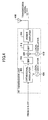
- Fig. 3 shows a (first) block diagram for illustrating a transmitter in accordance with one embodiment of the present invention.
- a base station includes N D data channel processing units 302-1 to 302-N D , a control channel processing unit 304, a multiplexing unit (MUX) 306, an Inverse Fast Fourier Transform (IFFT) unit 308, a guard interval insertion unit 310, a digital to analog (D/A) conversion unit 312, a symbol parameter adjusting unit 320, and a TTI adjusting unit 321.
- the N D data channel processing units 302-1 to 302-N D mutually have the same configuration and function, and the data channel processing unit 302-1 is representatively described hereinafter.
- the data channel processing unit 302-1 includes a turbo coder 322, a data modulator 324, an interleaver 326, and a serial to parallel (S/P) conversion unit 328.
- the control channel processing unit 304 includes a convolution coder 342, a QPSK modulator 344, an interleaver 346, and a serial to parallel (S/P) conversion unit 348.
- the N D data channel processing units 302-1 to 302-N D perform baseband processing for transmitting traffic information data in the OFDM system.
- the turbo coder 322 performs encoding for enhancing error tolerance of the traffic information data.
- the data modulator 324 modulates the traffic information data in accordance with a proper modulation scheme such as QPSK, 16QAM and 64QAM. In the case of adaptive modulation and coding (AMC), this modulation scheme is modified if needed.
- the interleaver 326 sorts the traffic information data in accordance with a predetermined pattern.
- the serial to parallel (S/P) conversion unit 328 converts a serial signal sequence (stream) into parallel signal sequences. The number of parallel signal sequences may be determined based on the number of subcarriers.
- the data channel processing units 302-1 to 302-N D perform the aforementioned operations for each transmission time interval supplied by the TTI adjusting unit 321.
- the control channel processing unit 304 performs baseband processing for transmitting control information data in OFDM system.
- the convolution coder 342 performs encoding for enhancing error tolerance of the control information data.
- the QPSK modulator 344 modulates the control information data in accordance with the QPSK modulation scheme. Any other proper modulation scheme may be employed, however, the QPSK modulation scheme with a lower number of modulation levels is employed in this embodiment due to the lesser amount of control information data.
- the interleaver 346 sorts the control information data in accordance with a predetermined pattern.
- the serial to parallel (S/P) conversion unit 348 converts a serial signal sequence into parallel signal sequences. The number of parallel signal sequences may be determined based on the number of subcarriers.
- the multiplexing unit (MUX) 306 multiplexes the processed (modulated, encoded, etc.) traffic information data and the processed control information data.
- a pilot channel (reference signal) may be input into the multiplexing unit 306 and multiplexed.
- a pilot channel may be input into the serial to parallel conversion unit 348 and multiplexed in the frequency direction, as shown by the dotted line in Fig. 3 .
- the multiplexing may be any scheme of time multiplexing, frequency multiplexing, or both time and frequency multiplexing.
- the Inverse Fast Fourier Transform unit 308 performs Inverse Fast Fourier Transform for an input signal, and then performs OFDM modulation.
- the guard interval insertion unit 310 generates a symbol in compliance with the OFDM system by adding a guard interval to the modulated signal.
- the guard interval is generated by duplicating part of the head or tail of the symbol to be transmitted.
- the digital to analog (D/A) conversion unit 312 converts a baseband digital signal into an analog signal.
- the symbol parameter adjusting unit 320 adjusts symbol parameters for use in communications.
- the symbol parameters include some information for defining the format of the OFDM symbols, and include a set of information items for defining values such as the period T GI of the guard interval, the period of the effective symbol, the share of the guard interval in a single symbol, and the subcarrier interval ⁇ f. It should be noted that the period of the effective symbol is equal to the reciprocal of the subcarrier interval 1/ ⁇ f.
- the symbol parameter adjusting unit 320 determines a proper set of symbol parameters depending on communication conditions or instructions from other devices. For example, the symbol parameter adjusting unit 320 may selectively use a different set of symbol parameters based on whether communications are carried out in accordance with the multicast scheme.
- a set of symbol parameters for defining the guard interval with a shorter period may be employed in the unicast scheme, whereas a set of symbol parameters for defining the guard interval with a longer period may be employed in the multicast scheme.
- the symbol parameter adjusting unit 320 may compute and derive a proper set of symbol parameters on a case-by-case basis.
- the symbol parameter adjusting unit 320 may store multiple sets of symbol parameters in a memory in advance and may select one of the sets of symbol parameters if needed. The manner of deriving the set of symbol parameters will be described below.
- the TTI adjusting unit 321 determines the length of the transmission time interval (TTI), and supplies the determined length of the transmission time interval to each data channel processing unit 302-1 to 302-N D , the multiplexing unit 306, and the symbol parameter adjusting unit 320.
- the length of the TTI may be determined based on information determined by an application such as a traffic size, information about the base station such as a frequency bandwidth, and/or information about a service type such as multicasting, unicasting, and broadcasting.
- the transmitter may notify the receiver of the determined length of the transmission time interval by means of some control signals. For example, the length of the transmission time interval may be determined when a call is connected.
- Fig. 4 shows a (second) block diagram for illustrating a transmitter in accordance with one embodiment of the present invention.
- the RF transmission unit includes an orthogonal modulator 402, a local oscillator 404, a bandpass filter 406, a mixer 408, a local oscillator 410, a bandpass filter 412, and a power amplifier 414.
- the orthogonal modulator 402 generates an in-phase component (I) and a quadrature component (Q) of an intermediate frequency from an input signal.
- the bandpass filter 406 removes a frequency component unnecessary for the intermediate frequency band.
- the mixer 408 uses the local oscillator 410 to convert (up-convert) the intermediate frequency signal into a high frequency signal.
- the bandpass filter 412 removes an unnecessary frequency component.
- the power amplifier 414 amplifies signal power for radio transmission from an antenna 416.
- Traffic information data input into the data channel processing unit in Fig. 3 is encoded by the turbo coder 322, is modulated by the data modulation unit 324, is sorted by the interleaver 326, and is made parallel by the serial to parallel converter 328.
- control information data is encoded, modulated, interleaved, and made parallel.
- Data channels and control channels are multiplexed for each subcarrier and for each transmission time interval by the multiplexing unit 306, and are OFDM modulated by the Inverse Fast Fourier Transform unit 308. Then, a guard interval is added to the modulated signal for outputting baseband OFDM symbols.
- the baseband signal is converted into an analog signal.
- the converted signal is orthogonally modulated by the orthogonal modulator 402 in the RF processing unit in Fig. 4 . After band-limiting, the modulated signal is properly amplified and transmitted.
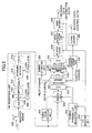
- Fig. 5 shows a block diagram for illustrating a receiver in accordance with one embodiment of the present invention.
- the receiver includes an antenna 502, a low noise amplifier 504, a mixer 506, a local oscillator 508, a bandpass filter 510, an automatic gain control unit 512, an orthogonal detector 514, a local oscillator 516, an analog to digital conversion unit 518, a symbol timing detection unit 520, a guard interval removal unit 522, a Fast Fourier Transform unit 524, a demultiplexer 526, a channel estimation unit 528, a channel compensation unit 530, a parallel to serial (P/S) conversion unit 532, a channel compensation unit 534, a deinterleaver 536, a data demodulation unit 537, a turbo decoder 538, a Viterbi decoder 540, a symbol parameter adjusting unit 542, and a TTI adjusting unit 544
- P/S parallel to serial
- the low noise amplifier 504 properly amplifies a signal received via the antenna 502.
- the amplified signal is converted (down-converted) into an intermediate frequency by the mixer 506 and the local oscillator 508.
- the bandpass filter 510 removes an unnecessary frequency component.
- the automatic gain control unit 512 controls the gain of the amplifier so as to properly maintain the signal level.
- the orthogonal detector 514 uses the local oscillator 516 to perform orthogonal demodulation based on an in-phase component (I) and a quadrature component (Q) of the received signal.
- the analog to digital conversion unit 518 converts an analog signal into a digital signal.
- the symbol timing detection unit 520 detects timing of symbols (symbol boundary) based on the digital signal.
- the guard interval removal unit 522 removes a portion corresponding to the guard interval from the received signal.
- the Fast Fourier Transform unit 524 performs Fast Fourier Transform for an input signal, and then performs OFDM demodulation.
- the demultiplexer 526 extracts pilot channels, control channels, and data channels multiplexed into a received signal. This extraction is performed corresponding to multiplexing at the transmitter (operations in the multiplexing unit 306 in Fig. 3 ).
- the channel estimation unit 528 uses the pilot channels to estimate conditions of the propagation path, and outputs a control signal for adjusting the amplitude and phase to compensate for the channel fluctuations. This control signal is output for each subcarrier.
- the channel compensation unit 530 adjusts the amplitude and phase of the data channels for each subcarrier based on information input from the channel estimation unit 528.
- the parallel to serial (P/S) conversion unit 532 converts parallel signal sequences into a serial signal sequence.
- the channel compensation unit 534 adjusts the amplitude and phase of the control channels for each subcarrier based on information input from the channel estimation unit 528.
- the deinterleaver 536 sorts signals in accordance with a predetermined pattern.
- the predetermined pattern corresponds to the inverse pattern for sorting in the interleaver (326 in Fig. 3 ) in the transmitter.
- the data demodulation unit 537 performs demodulation for the received signal for each transmission time interval, corresponding to the modulation scheme in the transmitter.
- the turbo coder 538 and the Viterbi decoder 540 decode traffic information data and control information data, respectively.
- the symbol parameter adjusting unit 542 determines symbol parameters for use in communications as is the case with the symbol parameter adjusting unit 320 in Fig. 3 .
- the symbol parameter adjusting unit 542 may compute and derive a proper set of symbol parameters on a case-by-case basis.
- the symbol parameter adjusting unit 542 may store multiple sets of symbol parameters in a memory in advance and access them if needed. The manner of deriving the set of symbol parameters will be described below.
- the TTI adjusting unit 544 determines the length of the transmission time interval, and supplies the determined length of the transmission time interval to the demultiplexer 526, the deinterleaver 536, the data demodulation unit 537, the turbo decoder 538, and the symbolparameter adjusting unit 542.
- the transmitter may notify the receiver of the determined length of the transmission time interval by means of some control signals. For example, the length of the transmission time interval may be determined when a call is connected.
- a signal received via an antenna is converted into a digital signal after amplification, frequency conversion, band-limiting, and orthogonal demodulation in the RF reception unit.
- the Fast Fourier Transform unit 524 performs an OFDM demodulation for a signal without a guard interval.
- the demodulated signal is demultiplexed into pilot channels, control channels, and data channels in the demultiplexer 526.
- the pilot channels are input to the channel estimation unit 528, and a compensation signal for compensating for channel fluctuations is output from the channel estimation unit 528 for each subcarrier.
- the data channels are compensated for by means of the compensation signal for each subcarrier and are converted into a serial signal.
- the converted signal is sorted by the deinterleaver 526 in accordance with the inverse pattern for sorting in the interleaver and is decoded in the turbo decoder 538.
- the control channels are also compensated for by means of the compensation signal and are decoded in the Viterbi decoder 540. Afterward, signal processing is carried out with use of the decoded data and control channels.
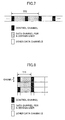
- Fig. 6 shows data transmission in accordance with the present embodiment.
- the transmission time interval TTI
- the transmission time interval TTI
- two types of TTI a long TTI and a short TTI
- the length of the frame is kept constant in order to meet the requirement for ensuring backward compatibility with existing communication systems.
- the long transmission time interval is twice longer than the short transmission time interval.
- the length of the frame is equal to 10 ms
- the length of the short TTI is equal to 0.5 ms
- the length of the long TTI is equal to 1.0 ms.
- a single frame includes 20 TTIs, whereas in the case of the long TTI, a single frame includes only 10 TTIs.
- two types of TTI are provided in Fig. 6 for ease of explanation, more types of TTI may be provided.
- the TTI controls various parameters for information transmission. For example, parameters such as a unit of packet transmission, a frequency of updating a data modulation scheme and a channel coding rate in the case of MCS, a unit of error correction coding, a unit of retransmission in the case of ARQ (Automatic Repeat reQuest), and a unit of packet scheduling are determined by the TTI. Because a control channel, which includes control information such as MCS information, retransmission information, and scheduling information, is used for demodulating a data channel, the control channel has to be used along with the data channel during each TTI. A longer TTI can reduce a frequency of inserting (allocating) the control channel, and can improve information transmission efficiency (see Fig. 7 ).
- This embodiment is also applicable to the case where a wide frequency band is divided into multiple frequency blocks (or chunks) and a unit of information transmission in the frequency direction is defined by the frequency block.
- the control channel may not be used for transmission for every chunk, but may be used for transmission only for a single chunk (see Fig. 8 ).
- Flexibly changing a unit of information transmission in the time direction and/or the frequency direction can prevent a frequency of inserting (allocating) the control channel from unnecessarily increasing, and can improve information transmission efficiency. Adjusting the length of the TTI is advantageous particularly in the case of a relatively narrow frequency band, because transmission efficiency is directly related to transmission delay when an available frequency band is narrow as shown in Fig. 7 .
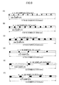
- the set of symbol parameters defines the subcarrier interval, the sampling frequency, the period of the effective symbol, the period of the guard interval, the number of symbols in a single TTI, and so on. It should be noted that all of the parameters cannot be determined independently. For example, the subcarrier interval and the period of the effective symbol have a reciprocal relationship with each other. Also, the period of a single TTI is derived by multiplying the period of one symbol (total period of the guard interval and the effective symbol) with the number of symbols. Three methods of deriving a second set of symbol parameters from a first set of symbol parameters are described below.
- the loss rate means a share of the guard interval in one symbol.
- the guard interval is a redundant portion from the viewpoint of improved data transmission efficiency.
- a first method of deriving a set of symbol parameters decreases the number of symbols in a single TTI and increases the period of the guard interval while keeping the subcarrier interval constant. For example, if a first set of symbol parameters now includes 10 symbols in a single TTI, the number of symbols is reduced to 9. Then, the period corresponding to the reduced one symbol (288 samples) is equally divided into 9 portions, each of which is assigned to the guard interval. As a result, as shown in Fig. 9(B) , while the period of the effective symbol (256 samples) is kept equal, the single TTI includes 9 symbols with longer periods of the guard interval.
- a second set of symbol parameters derived in this manner has the parameter values as follows.
- the second set of symbol parameters has the parameter values as follow ( Fig. 9(C) ).
- the period of the effective symbol is always kept constant, and thus the subcarrier interval can also be kept constant.
- the period of the guard interval and the number of symbols vary depending on the set of symbol parameters.
- a second method of deriving a set of symbol parameters changes the number of symbols in a single TTI while maintaining a constant loss rate.
- the share of the guard interval and the effective symbol has to be kept constant so as to fulfill the constant loss rate.
- the first set of symbol parameters as shown in Fig. 9(D) , the periods of the guard interval and the effective symbol are doubled respectively, and accordingly the number of symbols in one TTI can be reduced to 5 symbols.
- the second set of symbol parameters has the parameter values as follows.
- the second set of symbol parameters has the parameter values as follows.
- the period of a single TTI be extended from 0.5 ms to 1.0 ms, for example, so that an integral number of symbols are included in the single TTI.
- the constant loss rate can be maintained, and thus it is possible to derive sets of symbol parameters with equal data transmission efficiency.
- the loss rate increases accordingly.
- a third method of deriving a set of symbol parameters is configured as a combination of the first method and the second method.
- the first method may be applied to a first set of symbol parameters to derive a second set of symbol parameters
- the second method may be applied to the second set of symbol parameters to derive a third set of symbol parameters.
- the number of symbols is modified while maintaining the constant loss rate. For example, if the periods of the guard interval and the effective symbol are duplicated respectively, the third set of symbol parameters has the parameter values as follows ( Fig. 9(F) ).
- the period of a single TTI be extended to 1.0 ms, for example, so that an integral number of symbols are included in the single TTI.
- the third set of symbol parameters derived in this manner includes the same loss rate (20 %) as the set of symbol parameters shown in Fig. 9(B) , and includes the same subcarrier interval (11.25 kHz) as the set of symbol parameters shown in Fig. 9(D) .
- the period of the guard interval (128 samples) for the third set of symbol parameters is longer than any ones (64 samples) shown in Figs. 9(B) and 9(D) .
- all of the sets of symbol parameters are prepared for the same sampling frequency, it is not necessary to change clock frequency for each of the sets of parameters.
- 8 sets of symbol parameters can be derived by applying the first method and/or the second method to the first set of symbol parameters.
- new sets of symbol parameters have been derived in such a manner that the subcarrier interval and the number of symbols can be reduced from those of the reference set of symbol parameters.
- such new sets of symbol parameters may be derived in such a manner that the subcarrier interval and the number of symbols can be increased from those of the reference set of symbol parameters.
- the length of the transmission time interval is adjusted.
- the length of the guard interval and/or the effective symbol is modified.
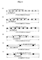
- Fig. 11(A) assume that the first set of symbol parameters is determined as follows. These parameter values are the same as those in Fig. 9(A) , except that the period of one TTI is extended from 0.5 ms to 1.0 ms.
- a first method of deriving a set of symbol parameters extends the period of the TTI, decreases the number of symbols in the single TTI, and increases the period of the guard interval while keeping the subcarrier interval constant. For example, if a first set of symbol parameters now includes 20 symbols in a single TTI, the number of symbols is reduced to 19. Then, the period corresponding to the reduced one symbol (288 samples) is equally divided into 19 portions, each of which is assigned to the guard interval. As a result, as shown in Fig. 11(B) , while the period of the effective symbol (256 samples) is kept equal, the single TTI includes 19 symbols with longer periods of the guard interval.
- a second set of symbol parameters derived in this manner has the parameter values as follows.
- the second set of symbol parameters has the parameter values as follow ( Fig. 11(C) ).
- the period of the effective symbol is always kept constant, and thus the subcarrier interval can also be kept constant.
- the period of the guard interval and the number of symbols vary depending on the set of symbol parameters.
- the number of symbols in one TTI is reduced by one symbol or two symbols, and the period corresponding to the reduced symbol(s) is equally divided into the guard intervals in the remaining symbols.
- the period corresponding to the reduced symbol(s) is equally divided into the guard intervals in the remaining symbols.
- the transmission time interval is extended twice as the transmission time interval in the examples shown Fig. 9 .
- the loss rate is equal to 20 % in the example shown in Fig. 9(B)
- the loss rate is reduced to 15.5 % in the example shown in Fig. 11(C) .
- the loss rate is equal to 28.9 % in the example shown in Fig. 9(C)
- the loss rate is reduced to 20.0 % in the example shown in Fig. 11(C) . Extending the length of the TTI in this manner can improve the loss rate, when the first method of the second embodiment is used.
- a second method of deriving a set of symbol parameters extends the period of the TTI, and changes the number of symbols in the single TTI while maintaining a constant loss rate.
- the share of the guard interval and the effective symbol has to be kept constant so as to fulfill the constant loss rate.
- the first set of symbol parameters as shown in Fig. 11(D)
- the periods of the guard interval and the effective symbol are doubled respectively, and accordingly the number of symbols in one TTI can be reduced to 10 symbols.
- the second set of symbol parameters has the parameter values as follows.
- the second set of symbol parameters has the parameter values as follows.
- the constant loss rate can be maintained, and thus it is possible to derive sets of symbol parameters with equal data transmission efficiency.
- the loss rate increases accordingly.
- the number of symbols in one TTI is equal to 2.5 symbols in the example shown in Fig. 9(E)
- the number of symbols is equal to 5 symbols in Fig. 11(E) .
- extending the length of the TTI allows the number of symbols in the single TTI to be adjusted to be an integer.
- a third method of deriving a set of symbol parameters is configured as a combination of the first method and the second method while extending the period of the TTI.
- the first method may be applied to a first set of symbol parameters to derive a second set of symbol parameters
- the second method may be applied to the second set of symbol parameters to derive a third set of symbol parameters.
- the loss rate is equal to 15.5 % for the second set of symbol parameters.
- the number of symbols is modified while maintaining the constant loss rate. For example, if the periods of the guard interval and the effective symbol are duplicated respectively, the third set of symbol parameters has the parameter values as follows ( Fig. 11(F) ).
- the third set of symbol parameters derived in this manner includes the same loss rate (15.5 %) as the set of symbol parameters shown in Fig. 11(B) , and includes the same subcarrier interval (11.25 kHz) as the set of symbol parameters shown in Fig. 11(D) .
- the period of the guard interval (94.3 samples) for the third set of symbol parameters is longer than any ones shown in Figs. 11(B) and 11(D) .
- the third method it is possible to efficiently derive a set of symbol parameters with a predetermined relationship between the subcarrier interval and the loss rate.
- the number of symbols included in the single TTI can be adjusted to be an integer.
Applications Claiming Priority (2)
| Application Number | Priority Date | Filing Date | Title |
|---|---|---|---|
| JP2005174396A JP4732808B2 (ja) | 2005-06-14 | 2005-06-14 | 無線パラメータ群を生成する装置 |
| EP06766507.5A EP1892866A4 (fr) | 2005-06-14 | 2006-06-08 | Recepteur, emetteur, appareil de generation de groupe de parametres radio |
Related Parent Applications (1)
| Application Number | Title | Priority Date | Filing Date |
|---|---|---|---|
| EP06766507.5A Division EP1892866A4 (fr) | 2005-06-14 | 2006-06-08 | Recepteur, emetteur, appareil de generation de groupe de parametres radio |
Publications (1)
| Publication Number | Publication Date |
|---|---|
| EP2696550A1 true EP2696550A1 (fr) | 2014-02-12 |
Family
ID=37532192
Family Applications (2)
| Application Number | Title | Priority Date | Filing Date |
|---|---|---|---|
| EP13191358.4A Withdrawn EP2696550A1 (fr) | 2005-06-14 | 2006-06-08 | Appareil de génération de paramètres radio, émetteur et récepteur |
| EP06766507.5A Withdrawn EP1892866A4 (fr) | 2005-06-14 | 2006-06-08 | Recepteur, emetteur, appareil de generation de groupe de parametres radio |
Family Applications After (1)
| Application Number | Title | Priority Date | Filing Date |
|---|---|---|---|
| EP06766507.5A Withdrawn EP1892866A4 (fr) | 2005-06-14 | 2006-06-08 | Recepteur, emetteur, appareil de generation de groupe de parametres radio |
Country Status (9)
| Country | Link |
|---|---|
| US (2) | US20090296833A1 (fr) |
| EP (2) | EP2696550A1 (fr) |
| JP (1) | JP4732808B2 (fr) |
| KR (1) | KR101242592B1 (fr) |
| CN (2) | CN101223721A (fr) |
| BR (1) | BRPI0612294A2 (fr) |
| RU (1) | RU2430475C2 (fr) |
| TW (1) | TW200705914A (fr) |
| WO (1) | WO2006134830A1 (fr) |
Cited By (2)
| Publication number | Priority date | Publication date | Assignee | Title |
|---|---|---|---|---|
| US8995563B2 (en) | 2007-04-27 | 2015-03-31 | Samsung Electronics Co., Ltd | Method and apparatus for transmitting and receiving uplink channel sounding reference signals in a wireless communication system |
| WO2017026594A1 (fr) * | 2015-08-13 | 2017-02-16 | 엘지전자 주식회사 | Procédé et appareil de commande de puissance dans un système de communication sans fil |
Families Citing this family (47)
| Publication number | Priority date | Publication date | Assignee | Title |
|---|---|---|---|---|
| JP4463723B2 (ja) | 2005-04-28 | 2010-05-19 | 株式会社エヌ・ティ・ティ・ドコモ | 送信機及び送信方法 |
| US7894818B2 (en) * | 2005-06-15 | 2011-02-22 | Samsung Electronics Co., Ltd. | Apparatus and method for multiplexing broadcast and unicast traffic in a multi-carrier wireless network |
| US8737313B2 (en) * | 2006-08-07 | 2014-05-27 | Qualcomm Incorporated | Transmit time segments for asynchronous wireless communication |
| US8310996B2 (en) * | 2006-08-07 | 2012-11-13 | Qualcomm Incorporated | Conditional scheduling for asynchronous wireless communication |
| US8416762B2 (en) * | 2006-08-07 | 2013-04-09 | Qualcomm Incorporated | Message exchange scheme for asynchronous wireless communication |
| US8340027B2 (en) * | 2006-08-07 | 2012-12-25 | Qualcomm Incorporated | Monitor period for asynchronous wireless communication |
| US9008002B2 (en) | 2006-08-07 | 2015-04-14 | Qualcomm Incorporated | Conditional requests for asynchronous wireless communication |
| JP2008193414A (ja) | 2007-02-05 | 2008-08-21 | Nec Corp | 無線通信システム、その上りリンクにおけるデータ送信方法、基地局装置及び移動局装置 |
| JP2008252315A (ja) * | 2007-03-29 | 2008-10-16 | Kddi Corp | 無線装置 |
| JP4940115B2 (ja) * | 2007-07-13 | 2012-05-30 | 株式会社日立製作所 | 無線通信システム、無線端末および無線基地局 |
| JP5195906B2 (ja) * | 2008-04-08 | 2013-05-15 | 日本電気株式会社 | 無線通信システム、無線通信装置、無線通信方法、プログラム |
| CN101572905B (zh) * | 2008-04-30 | 2014-06-04 | 华为技术有限公司 | 传输时间间隔的调整方法和装置 |
| CN102017448B (zh) * | 2008-04-30 | 2015-07-29 | 皇家飞利浦电子股份有限公司 | 用于向无线电站用信令告知资源的方法及用于此的无线电站 |
| KR101507850B1 (ko) * | 2008-05-29 | 2015-04-07 | 엘지전자 주식회사 | 이동 통신 시스템에서 제어 정보를 상향 전송하는 방법 |
| US8494065B2 (en) | 2008-06-09 | 2013-07-23 | Qualcomm Incorporated | Interference reduction between OFDM carriers by frequency offset optimization |
| CN101932101B (zh) * | 2009-06-19 | 2015-03-11 | 华为技术有限公司 | 传输时间间隔的调整方法和网络设备 |
| JP4733200B2 (ja) * | 2009-08-20 | 2011-07-27 | 株式会社エヌ・ティ・ティ・ドコモ | 受信装置 |
| MX2012003399A (es) * | 2009-09-30 | 2012-04-10 | Ericsson Telefon Ab L M | Reconfiguracion de conjunto de portadores de componente activo en sistemas inalambricos de portadores multiples. |
| CN102065046B (zh) * | 2009-11-11 | 2013-10-09 | 北京泰美世纪科技有限公司 | 一种ofdm系统的信息传输方法及信号生成装置 |
| GB2495473A (en) * | 2011-10-03 | 2013-04-17 | Renesas Mobile Corp | Modifying transmission time interval (tti) allocation using high speed shared control channel (hs-scch) order |
| ITTO20120242A1 (it) * | 2012-03-19 | 2013-09-20 | Rai Radiotelevisione Italiana | Metodo per generare un segnale di tipo vcm o acm a trama perfezionata |
| WO2014060010A1 (fr) * | 2012-10-15 | 2014-04-24 | Nokia Solutions And Networks Oy | Structure de trame flexible |
| WO2014158205A1 (fr) * | 2013-03-26 | 2014-10-02 | Empire Technology Development, Llc | Allocation spectrale prédictive dans des réseaux mobiles |
| WO2014200512A1 (fr) | 2013-06-11 | 2014-12-18 | Empire Technology Development, Llc | Transition progressive entre attribution spectrale prédictive et assistée par les mobiles |
| EP3136644A4 (fr) * | 2014-05-15 | 2017-05-10 | Huawei Technologies Co., Ltd. | Appareils et procédés de transmission de données |
| CN106664187A (zh) | 2014-06-02 | 2017-05-10 | 马维尔国际贸易有限公司 | 高效正交频分复用(ofdm)物理层(phy) |
| US9980257B2 (en) * | 2014-09-26 | 2018-05-22 | Qualcomm Incorporated | Ultra-low latency LTE reference signal transmission |
| US9955462B2 (en) | 2014-09-26 | 2018-04-24 | Qualcomm Incorporated | Ultra-low latency LTE control data communication |
| WO2016064039A1 (fr) * | 2014-10-21 | 2016-04-28 | 엘지전자(주) | Procédé d'émission/réception de données dans un système de communication sans fil qui supporte un faible temps de latence, et appareil correspondant |
| US10455503B2 (en) | 2014-10-21 | 2019-10-22 | Lg Electronics Inc. | Method for monitoring downlink control channel in wireless communication system and apparatus for the same |
| US10939454B2 (en) * | 2014-12-11 | 2021-03-02 | Qualcomm Incorporated | Prioritizing colliding transmissions in LTE and ultra-low latency LTE communications |
| WO2016142978A1 (fr) * | 2015-03-06 | 2016-09-15 | 日本電気株式会社 | Station sans fil, dispositif terminal sans fil, et procédé correspondant |
| EP3793294A1 (fr) | 2015-03-06 | 2021-03-17 | NEC Corporation | Configuration pour intervalle de temps de transmission court |
| CN107432020B (zh) * | 2015-03-12 | 2021-06-08 | Lg 电子株式会社 | 在短tti中减少用于控制信道的传输资源的方法和设备 |
| US10547415B2 (en) * | 2015-03-15 | 2020-01-28 | Qualcomm Incorporated | Scalable TTI with advanced pilot and control |
| WO2016175596A1 (fr) * | 2015-04-29 | 2016-11-03 | Lg Electronics Inc. | Procédé et appareil de réception d'informations système et de radiomessagerie dans un tti court, dans un système de communication sans fil |
| US10383105B2 (en) | 2015-07-12 | 2019-08-13 | Lg Electronics Inc. | Method and device for transmitting control information in wireless communication system |
| US20180206232A1 (en) * | 2015-07-17 | 2018-07-19 | Ntt Docomo, Inc. | User terminal, radio base station, and radio communication method |
| CN107852313B (zh) * | 2015-07-24 | 2021-08-03 | Lg 电子株式会社 | 下行链路控制信息接收方法和用户设备以及下行链路控制信息发送方法和基站 |
| CA2990488A1 (fr) | 2015-09-16 | 2017-03-23 | Guangdong Oppo Mobile Telecommunications Corp., Ltd. | Procede et dispositif pour regler des parametres de communication |
| EP3313133A4 (fr) | 2015-10-31 | 2019-01-23 | Guangdong Oppo Mobile Telecommunications Corp., Ltd. | Procédé d'indication de ressource, station de base et terminal |
| CN107925670B (zh) * | 2015-11-27 | 2020-06-16 | 华为技术有限公司 | 一种信道调整方法、对应装置及系统 |
| WO2017115609A1 (fr) * | 2015-12-28 | 2017-07-06 | ソニー株式会社 | Dispositif et procédé |
| US10440729B2 (en) | 2016-07-28 | 2019-10-08 | Qualcomm Incorporated | Transmission of Ultra-Reliable Low-Latency Communications (URLLC) over Time Division Duplex (TDD) using a URLLC configuration for a TDD subframe |
| US10129058B2 (en) * | 2016-09-16 | 2018-11-13 | Nokia Solutions And Networks Oy | Demodulation reference signal based automatic gain control |
| CN116506260A (zh) * | 2016-09-29 | 2023-07-28 | 松下电器(美国)知识产权公司 | 通信方法、通信装置和通信系统 |
| US11323966B2 (en) * | 2016-10-28 | 2022-05-03 | Qualcomm Incorporated | Uplink transmission techniques in low latency wireless communication systems |
Citations (3)
| Publication number | Priority date | Publication date | Assignee | Title |
|---|---|---|---|---|
| EP1298948A1 (fr) * | 2001-05-16 | 2003-04-02 | Matsushita Electric Industrial Co., Ltd. | Station de base radio et terminal de communication |
| WO2006105005A2 (fr) * | 2005-03-30 | 2006-10-05 | Motorola, Inc. | Procede et appareil destines a reduire le temps d'attente d'aller-retour et le surdebit dans un systeme de communication |
| EP1881628A1 (fr) * | 2005-04-28 | 2008-01-23 | NTT DoCoMo Inc. | Appareil de creation de groupes de parametres radio, transmetteur et recepteur |
Family Cites Families (21)
| Publication number | Priority date | Publication date | Assignee | Title |
|---|---|---|---|---|
| DE4425713C1 (de) * | 1994-07-20 | 1995-04-20 | Inst Rundfunktechnik Gmbh | Verfahren zur Vielträger Modulation und Demodulation von digital codierten Daten |
| JP2852295B2 (ja) * | 1997-05-26 | 1999-01-27 | 株式会社次世代デジタルテレビジョン放送システム研究所 | Ofdm信号復調装置 |
| JP3421671B2 (ja) * | 1999-09-30 | 2003-06-30 | 独立行政法人通信総合研究所 | 通信システム、選択装置、送信装置、受信装置、選択方法、送信方法、受信方法、および、情報記録媒体 |
| JP3581072B2 (ja) * | 2000-01-24 | 2004-10-27 | 株式会社エヌ・ティ・ティ・ドコモ | チャネル構成方法及びその方法を利用する基地局 |
| US6721569B1 (en) * | 2000-09-29 | 2004-04-13 | Nortel Networks Limited | Dynamic sub-carrier assignment in OFDM systems |
| US7023933B2 (en) * | 2000-10-20 | 2006-04-04 | Matsushita Electric Industrial Co., Ltd. | Radio communication apparatus |
| JP3746048B2 (ja) * | 2000-11-06 | 2006-02-15 | 松下電器産業株式会社 | 無線通信装置 |
| DE60104113T2 (de) * | 2001-08-22 | 2004-10-28 | Matsushita Electric Industrial Co., Ltd., Kadoma | Übertragungsverfahren und Übertragungsgerät mit Mehrkanal-ARQ |
| US20040081131A1 (en) * | 2002-10-25 | 2004-04-29 | Walton Jay Rod | OFDM communication system with multiple OFDM symbol sizes |
| JP2004214961A (ja) * | 2002-12-27 | 2004-07-29 | Sony Corp | Ofdm復調装置 |
| KR100510861B1 (ko) * | 2003-01-18 | 2005-08-31 | 디지피아(주) | 직교 주파수 분할 다중 전송 시스템에서의 훈련 신호 결정방법 및 그 훈련 신호를 이용한 직교 주파수 분할 다중수신기와 수신 방법 |
| KR100584431B1 (ko) * | 2003-02-14 | 2006-05-26 | 삼성전자주식회사 | 부호 분할 다중 접속 통신 시스템에서 역방향 데이터재전송 시스템 및 방법 |
| US7203245B1 (en) * | 2003-03-31 | 2007-04-10 | 3Com Corporation | Symbol boundary detector method and device for OFDM systems |
| EP1489773A1 (fr) * | 2003-06-16 | 2004-12-22 | Mitsubishi Electric Information Technology Centre Europe B.V. | Procédé de cadencement avec demande de répétition arrêt et pause |
| KR101009861B1 (ko) * | 2003-08-19 | 2011-01-19 | 삼성전자주식회사 | 이동통신 시스템에서의 데이터 전송 방법과 전송률 할당 방법 및 이를 위한 장치 |
| JP2005117579A (ja) * | 2003-10-10 | 2005-04-28 | Fujitsu Ltd | 無線送信装置,無線受信装置,移動通信システムおよび無線リソース制御方法 |
| JP4291674B2 (ja) * | 2003-11-11 | 2009-07-08 | 株式会社エヌ・ティ・ティ・ドコモ | Ofdm送信機及びofdm受信機 |
| US7570953B2 (en) * | 2004-01-12 | 2009-08-04 | Intel Corporation | Multicarrier communication system and methods for link adaptation using uniform bit loading and subcarrier puncturing |
| ES2774204T3 (es) * | 2004-04-01 | 2020-07-17 | Optis Wireless Technology Llc | Limitación de interferencia para las retransmisiones |
| KR100735346B1 (ko) * | 2004-05-04 | 2007-07-04 | 삼성전자주식회사 | 향상된 상향 링크 전용 채널에서 harq 동작을 고려한tti 변경 방법 및 장치 |
| KR101089526B1 (ko) * | 2006-01-11 | 2011-12-05 | 퀄컴 인코포레이티드 | 피어-투-피어 통신 시스템에서 파라미터 선택 |
-
2005
- 2005-06-14 JP JP2005174396A patent/JP4732808B2/ja active Active
-
2006
- 2006-06-08 US US11/917,734 patent/US20090296833A1/en not_active Abandoned
- 2006-06-08 EP EP13191358.4A patent/EP2696550A1/fr not_active Withdrawn
- 2006-06-08 EP EP06766507.5A patent/EP1892866A4/fr not_active Withdrawn
- 2006-06-08 BR BRPI0612294-9A patent/BRPI0612294A2/pt not_active Application Discontinuation
- 2006-06-08 RU RU2008100083/09A patent/RU2430475C2/ru not_active IP Right Cessation
- 2006-06-08 WO PCT/JP2006/311545 patent/WO2006134830A1/fr active Application Filing
- 2006-06-08 CN CNA2006800261630A patent/CN101223721A/zh active Pending
- 2006-06-08 CN CN201310043529.7A patent/CN103152306B/zh active Active
- 2006-06-08 KR KR1020087000766A patent/KR101242592B1/ko active IP Right Grant
- 2006-06-13 TW TW095120962A patent/TW200705914A/zh unknown
-
2011
- 2011-12-27 US US13/337,613 patent/US8483043B2/en active Active
Patent Citations (3)
| Publication number | Priority date | Publication date | Assignee | Title |
|---|---|---|---|---|
| EP1298948A1 (fr) * | 2001-05-16 | 2003-04-02 | Matsushita Electric Industrial Co., Ltd. | Station de base radio et terminal de communication |
| WO2006105005A2 (fr) * | 2005-03-30 | 2006-10-05 | Motorola, Inc. | Procede et appareil destines a reduire le temps d'attente d'aller-retour et le surdebit dans un systeme de communication |
| EP1881628A1 (fr) * | 2005-04-28 | 2008-01-23 | NTT DoCoMo Inc. | Appareil de creation de groupes de parametres radio, transmetteur et recepteur |
Non-Patent Citations (2)
| Title |
|---|
| NTT DOCOMO: "Physical Channel Structures for Evolved UTRA", 3GPP DRAFT; R1-050464_PHYSICAL CHANNEL, 3RD GENERATION PARTNERSHIP PROJECT (3GPP), MOBILE COMPETENCE CENTRE ; 650, ROUTE DES LUCIOLES ; F-06921 SOPHIA-ANTIPOLIS CEDEX ; FRANCE, vol. RAN WG1, no. Athens, Greece; 20050503, 3 May 2005 (2005-05-03), XP050100152 * |
| OHTSU: "Systems beyond IMT-2000", ITU JOURNAL, vol. 33, no. 3, March 2000 (2000-03-01), pages 26 - 30 |
Cited By (5)
| Publication number | Priority date | Publication date | Assignee | Title |
|---|---|---|---|---|
| US8995563B2 (en) | 2007-04-27 | 2015-03-31 | Samsung Electronics Co., Ltd | Method and apparatus for transmitting and receiving uplink channel sounding reference signals in a wireless communication system |
| US9986538B2 (en) | 2007-04-27 | 2018-05-29 | Samsung Electronics Co., Ltd | Method and apparatus for transmitting and receiving uplink channel sounding reference signals in a wireless communication system |
| US11051281B2 (en) | 2007-04-27 | 2021-06-29 | Samsung Electronics Co., Ltd | Method and apparatus for transmitting and receiving uplink channel sounding reference signals in a wireless communication system |
| WO2017026594A1 (fr) * | 2015-08-13 | 2017-02-16 | 엘지전자 주식회사 | Procédé et appareil de commande de puissance dans un système de communication sans fil |
| US10440662B2 (en) | 2015-08-13 | 2019-10-08 | Lg Electronics Inc. | Method and apparatus for controlling power in wireless communication system |
Also Published As
| Publication number | Publication date |
|---|---|
| KR20080021775A (ko) | 2008-03-07 |
| CN103152306A (zh) | 2013-06-12 |
| TWI312629B (fr) | 2009-07-21 |
| EP1892866A4 (fr) | 2013-09-04 |
| TW200705914A (en) | 2007-02-01 |
| US20090296833A1 (en) | 2009-12-03 |
| US20120093257A1 (en) | 2012-04-19 |
| RU2430475C2 (ru) | 2011-09-27 |
| US8483043B2 (en) | 2013-07-09 |
| JP2006352379A (ja) | 2006-12-28 |
| CN103152306B (zh) | 2016-06-29 |
| RU2008100083A (ru) | 2009-07-20 |
| EP1892866A1 (fr) | 2008-02-27 |
| KR101242592B1 (ko) | 2013-03-19 |
| JP4732808B2 (ja) | 2011-07-27 |
| CN101223721A (zh) | 2008-07-16 |
| WO2006134830A1 (fr) | 2006-12-21 |
| BRPI0612294A2 (pt) | 2010-11-03 |
Similar Documents
| Publication | Publication Date | Title |
|---|---|---|
| US8483043B2 (en) | Apparatus for generating a set of radio parameters, a transmitter and a receiver | |
| EP1881628B1 (fr) | Appareil de création de groupes de paramètres radio, transmetteur et récepteur | |
| RU2421916C2 (ru) | Передающее устройство и способ передачи данных | |
| CN101507222B (zh) | 在无线通信系统中包括dc子载波的资源分配 | |
| JP4733200B2 (ja) | 受信装置 | |
| JP4782220B2 (ja) | 受信機及び受信方法 | |
| JP4782229B2 (ja) | 送信機及び送信方法、移動通信システム |
Legal Events
| Date | Code | Title | Description |
|---|---|---|---|
| 17P | Request for examination filed |
Effective date: 20131104 |
|
| AC | Divisional application: reference to earlier application |
Ref document number: 1892866 Country of ref document: EP Kind code of ref document: P |
|
| AK | Designated contracting states |
Kind code of ref document: A1 Designated state(s): AT BE BG CH CY CZ DE DK EE ES FI FR GB GR HU IE IS IT LI LT LU LV MC NL PL PT RO SE SI SK TR |
|
| PUAI | Public reference made under article 153(3) epc to a published international application that has entered the european phase |
Free format text: ORIGINAL CODE: 0009012 |
|
| 17Q | First examination report despatched |
Effective date: 20150708 |
|
| GRAP | Despatch of communication of intention to grant a patent |
Free format text: ORIGINAL CODE: EPIDOSNIGR1 |
|
| INTG | Intention to grant announced |
Effective date: 20160808 |
|
| 18D | Application deemed to be withdrawn |
Effective date: 20161220 |
|
| STAA | Information on the status of an ep patent application or granted ep patent |
Free format text: STATUS: THE APPLICATION IS DEEMED TO BE WITHDRAWN |