EP2696184A2 - Verfahren zur Identifikation lokaler Werkstoffdämpfung in Verbund-Strukturen - Google Patents
Verfahren zur Identifikation lokaler Werkstoffdämpfung in Verbund-Strukturen Download PDFInfo
- Publication number
- EP2696184A2 EP2696184A2 EP13002859.0A EP13002859A EP2696184A2 EP 2696184 A2 EP2696184 A2 EP 2696184A2 EP 13002859 A EP13002859 A EP 13002859A EP 2696184 A2 EP2696184 A2 EP 2696184A2
- Authority
- EP
- European Patent Office
- Prior art keywords
- damping
- sensor
- attenuation
- vibration
- lightweight component
- Prior art date
- Legal status (The legal status is an assumption and is not a legal conclusion. Google has not performed a legal analysis and makes no representation as to the accuracy of the status listed.)
- Granted
Links
- 238000013016 damping Methods 0.000 title claims abstract description 32
- 238000000034 method Methods 0.000 title claims abstract description 24
- 239000002131 composite material Substances 0.000 title abstract description 6
- 239000000463 material Substances 0.000 claims abstract description 42
- 238000007689 inspection Methods 0.000 claims abstract description 4
- 238000012423 maintenance Methods 0.000 claims abstract description 4
- 230000010355 oscillation Effects 0.000 claims description 6
- 239000004033 plastic Substances 0.000 claims 2
- 229920003023 plastic Polymers 0.000 claims 2
- 239000004918 carbon fiber reinforced polymer Substances 0.000 claims 1
- 239000011152 fibreglass Substances 0.000 claims 1
- 230000007547 defect Effects 0.000 description 5
- 239000003365 glass fiber Substances 0.000 description 5
- 239000011159 matrix material Substances 0.000 description 4
- 238000005259 measurement Methods 0.000 description 3
- 230000001902 propagating effect Effects 0.000 description 3
- 238000009827 uniform distribution Methods 0.000 description 3
- 230000001419 dependent effect Effects 0.000 description 2
- 238000001514 detection method Methods 0.000 description 2
- 238000010586 diagram Methods 0.000 description 2
- 239000000835 fiber Substances 0.000 description 2
- 229920000642 polymer Polymers 0.000 description 2
- 230000002123 temporal effect Effects 0.000 description 2
- 229920000049 Carbon (fiber) Polymers 0.000 description 1
- 210000001015 abdomen Anatomy 0.000 description 1
- 230000003044 adaptive effect Effects 0.000 description 1
- 239000004917 carbon fiber Substances 0.000 description 1
- 230000001066 destructive effect Effects 0.000 description 1
- 238000003745 diagnosis Methods 0.000 description 1
- 239000006185 dispersion Substances 0.000 description 1
- 230000000694 effects Effects 0.000 description 1
- 210000004177 elastic tissue Anatomy 0.000 description 1
- 230000005684 electric field Effects 0.000 description 1
- 239000002657 fibrous material Substances 0.000 description 1
- 238000004519 manufacturing process Methods 0.000 description 1
- 238000000691 measurement method Methods 0.000 description 1
- 230000007246 mechanism Effects 0.000 description 1
- 238000012544 monitoring process Methods 0.000 description 1
- 230000021715 photosynthesis, light harvesting Effects 0.000 description 1
- 230000010287 polarization Effects 0.000 description 1
- 230000000750 progressive effect Effects 0.000 description 1
- 238000004513 sizing Methods 0.000 description 1
- 238000012360 testing method Methods 0.000 description 1
- 230000007704 transition Effects 0.000 description 1
- 238000012800 visualization Methods 0.000 description 1
Images

Classifications
-
- G—PHYSICS
- G01—MEASURING; TESTING
- G01M—TESTING STATIC OR DYNAMIC BALANCE OF MACHINES OR STRUCTURES; TESTING OF STRUCTURES OR APPARATUS, NOT OTHERWISE PROVIDED FOR
- G01M5/00—Investigating the elasticity of structures, e.g. deflection of bridges or air-craft wings
- G01M5/0016—Investigating the elasticity of structures, e.g. deflection of bridges or air-craft wings of aircraft wings or blades
-
- G—PHYSICS
- G01—MEASURING; TESTING
- G01M—TESTING STATIC OR DYNAMIC BALANCE OF MACHINES OR STRUCTURES; TESTING OF STRUCTURES OR APPARATUS, NOT OTHERWISE PROVIDED FOR
- G01M5/00—Investigating the elasticity of structures, e.g. deflection of bridges or air-craft wings
- G01M5/0033—Investigating the elasticity of structures, e.g. deflection of bridges or air-craft wings by determining damage, crack or wear
-
- G—PHYSICS
- G01—MEASURING; TESTING
- G01M—TESTING STATIC OR DYNAMIC BALANCE OF MACHINES OR STRUCTURES; TESTING OF STRUCTURES OR APPARATUS, NOT OTHERWISE PROVIDED FOR
- G01M5/00—Investigating the elasticity of structures, e.g. deflection of bridges or air-craft wings
- G01M5/0066—Investigating the elasticity of structures, e.g. deflection of bridges or air-craft wings by exciting or detecting vibration or acceleration
-
- G—PHYSICS
- G01—MEASURING; TESTING
- G01M—TESTING STATIC OR DYNAMIC BALANCE OF MACHINES OR STRUCTURES; TESTING OF STRUCTURES OR APPARATUS, NOT OTHERWISE PROVIDED FOR
- G01M7/00—Vibration-testing of structures; Shock-testing of structures
-
- G—PHYSICS
- G01—MEASURING; TESTING
- G01N—INVESTIGATING OR ANALYSING MATERIALS BY DETERMINING THEIR CHEMICAL OR PHYSICAL PROPERTIES
- G01N29/00—Investigating or analysing materials by the use of ultrasonic, sonic or infrasonic waves; Visualisation of the interior of objects by transmitting ultrasonic or sonic waves through the object
- G01N29/04—Analysing solids
- G01N29/043—Analysing solids in the interior, e.g. by shear waves
-
- G—PHYSICS
- G01—MEASURING; TESTING
- G01N—INVESTIGATING OR ANALYSING MATERIALS BY DETERMINING THEIR CHEMICAL OR PHYSICAL PROPERTIES
- G01N29/00—Investigating or analysing materials by the use of ultrasonic, sonic or infrasonic waves; Visualisation of the interior of objects by transmitting ultrasonic or sonic waves through the object
- G01N29/04—Analysing solids
- G01N29/11—Analysing solids by measuring attenuation of acoustic waves
-
- G—PHYSICS
- G01—MEASURING; TESTING
- G01N—INVESTIGATING OR ANALYSING MATERIALS BY DETERMINING THEIR CHEMICAL OR PHYSICAL PROPERTIES
- G01N29/00—Investigating or analysing materials by the use of ultrasonic, sonic or infrasonic waves; Visualisation of the interior of objects by transmitting ultrasonic or sonic waves through the object
- G01N29/22—Details, e.g. general constructional or apparatus details
- G01N29/24—Probes
- G01N29/2475—Embedded probes, i.e. probes incorporated in objects to be inspected
-
- G—PHYSICS
- G01—MEASURING; TESTING
- G01N—INVESTIGATING OR ANALYSING MATERIALS BY DETERMINING THEIR CHEMICAL OR PHYSICAL PROPERTIES
- G01N2291/00—Indexing codes associated with group G01N29/00
- G01N2291/02—Indexing codes associated with the analysed material
- G01N2291/023—Solids
- G01N2291/0231—Composite or layered materials
-
- G—PHYSICS
- G01—MEASURING; TESTING
- G01N—INVESTIGATING OR ANALYSING MATERIALS BY DETERMINING THEIR CHEMICAL OR PHYSICAL PROPERTIES
- G01N2291/00—Indexing codes associated with group G01N29/00
- G01N2291/26—Scanned objects
- G01N2291/269—Various geometry objects
- G01N2291/2694—Wings or other aircraft parts
Definitions
- the invention relates to a method for identifying locally distributed material damping in composite structures, which can be used in particular in the inspection, maintenance or servicing of lightweight components that have materials with high mechanical requirements, such as the outer skin of Flugkörpezn.
- the invention further relates to a method for the experimental determination of inhomogeneously distributed material damping.
- composites which are usually made of a viscoelastic matrix material and embedded fibers, such as carbon fibers or glass fibers, there are a variety of mechanisms and methods for determining the material damping.
- diagnostic systems For materials subject to high mechanical stresses, diagnostic systems are used which determine the damage based on condition-sensitive measurable quantities.
- the reliability of the diagnosis made depends strongly on the correct selection of damage-dependent input variables. As one of these state-sensitive variables, the determination of the material damping is well known.
- the operation-relevant damage-induced changes in the damping characteristic usually occur locally, which causes a local and anisotropic change in the material damping
- a disadvantage of the known solutions is the detection of local damping on the one hand by the change in the sensor position, the measurement procedure is very time and labor intensive because of the constant position change of the sensor.
- the detection of the local damping can be carried out further by equipping the test specimen with a plurality of sensors, the number of sensors influencing the attenuation value of the material to be measured and thus subjecting the measurement to a greater error.
- the object of the invention is therefore to further develop a method for measuring local material damping so that a determination of the local material damping permits can be used in a short time and under non-invasive conditions.
- the method is based on the use of a tunable, quasi-stationary mechanical vibration, which changes by a definable change in the position of the wave crest, the proportion of damping of selected material areas.
- An advantage of the method according to the invention is the uncomplicated, low-interference and associated with little time implementation of the measurement method at the same time high location and directionality.
- the damping properties in components, in particular made of composite materials should be assessed and determined. It must be qualitatively localized where and how much attenuation has taken place. Furthermore, the size of the attenuation is analyzed and the temporal change of the attenuation is measured. As a result, a progressive crack growth can be detected inside the component to be measured.
- the procedure ensures that a non-destructive identification of the components takes place.
- piezoelectric materials are well suited for embedding in fiber composites, that is for embedding in materials of bonded materials.
- a mechanical deformation can be generated by an electric field.
- different mechanical deformations can be generated or detected.
- Another advantage is the possibility of online monitoring.
- the body of the material to be measured can be tested online during its use for material changes. Time-consuming shutdowns for inspections or maintenance can be reduced or even avoided.
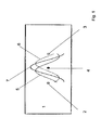
- a body 1 can be seen, which has actuators 2, 3 for the vibrations 5, 6 at two positions and between these actuators 2, 3, a sensor 4 is positioned. Each of the two actuators 2, 3 sends out a vibration 5, 6, the resulting standing wave 7 being measured by the sensor 4.
- a body 1 of embedded in a polymer matrix glass fibers are two positioned actuators 2 and 3 and a sensor 4 after Fig. 1 introduced, which emit a mechanical vibration 5 and 6 of the same amplitude and wavelength on the respective other actuator. Due to the interference of both waves 5 and 6 creates a standing wave 7 in the body.
- the defect is localized by computing the dissipated energy of the standing wave 7. From this information, an estimate of the damage state and the location of the damage to the body 1 can again be made.
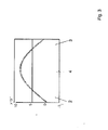
- Fig. 2 Based on Fig. 2 is a uniform distribution of damping along the route between the actuators 2 and 3 with the structure Fig. 1 seen.
- a body 1 of embedded in a polymer matrix glass fibers are two positioned actuators 2 and 3 and a sensor 4 after Fig. 1 introduced, which send out a mechanical vibration 5 and 6 on the respective other actuator.
- the initial phase and amplitude of the propagating vibrations 5 and 6 are changed steplessly, so that the position of the wave belly is at the level of the sensor 4.
Landscapes
- Physics & Mathematics (AREA)
- General Physics & Mathematics (AREA)
- Chemical & Material Sciences (AREA)
- Aviation & Aerospace Engineering (AREA)
- Health & Medical Sciences (AREA)
- Life Sciences & Earth Sciences (AREA)
- Engineering & Computer Science (AREA)
- Analytical Chemistry (AREA)
- Biochemistry (AREA)
- General Health & Medical Sciences (AREA)
- Immunology (AREA)
- Pathology (AREA)
- Acoustics & Sound (AREA)
- Investigating Or Analyzing Materials By The Use Of Ultrasonic Waves (AREA)
- Investigating Strength Of Materials By Application Of Mechanical Stress (AREA)
Abstract
Description
- Die Erfindung betrifft ein Verfahren zur Identifikation lokal verteilter Werkstoffdämpfung in Verbund-Strukturen, die insbesondere bei der Inspektion, Wartung oder Instand-haltung von Leichtbau-Komponenten, die Werkstoffe mit hohen mechanischen Anforderungen aufweisen, wie beispielsweise der Außenhaut von Flugkörpezn, eingesetzt werden kann.
- Die Erfindung betrifft des Weiteren ein Verfahren zur experimentellen Bestimmung inhomogen verteilter Werkstoffdämpfung. Speziell bei Verbundwerkstoffen, die in der Regel aus einem viskoelastischen Matrixmaterial und darin eingebetteten Fasern, wie beispielsweise Kohlenstofffasern oder Glasfasern bestehen, gibt es vielfältige Mechanismen und Verfahren zur Bestimmung der Werkstoffdämpfung.
- Unter Werkstoffdämpfung wird die durch örtlich und zeitlich bewirkte Energiedissipation im viskoseelastischen Matrixmaterial, im elastischen Fasermaterial und an den Materialgrenzen und Übergängen, die wiederum durch fertigungstechnische Besonderheiten wie Fehlstellen, Einschlüsse, Beugung und Schlichte gekennzeichnet sind. Darüber hinaus kommt es infolge der Bauteilbeanspruchung im Regalbetrieb und besonders bei lokalen Schadensereignissen, wie beispielsweise Stoßereignissen ohne Totalschaden, zu einer Veränderung der lokalen Werkstoffdämpfung.
- Bei Werkstoffen, die hohen mechanischen Belastungen ausgesetzt sind, werden diagnostische Systeme angewendet, die basierend auf zustandasensitive messbare Größen die Schädigung ermitteln,
- Die Zuverlässigkeit der getroffenen Diagnose hängt stark mit der richtigen Auswahl schädigungsabhängiger Eingangsgrößen zusammen. Als eine dieser zustandssensitiven Größen ist die Bestimmung der Werkstoffdämpfung allgemein bekannt.
- Die betriebsrelevanten schädigungsinduzierten Änderungen der Dämpfungscharakteristik treten meist lokal auf, welches eine lokale und anisotrope Veränderung der Werkstoff-dämpfung verursacht,
- Bei der Verwendung der lokalon Werkstoffdämpfung als dia-gnostische Eingangsgröße besteht das Hauptproblem in der Bestimmung der Werkstoffdämpfung mit ausreichender Orts-und Richtungsauflösung.
- Herkömmlich ist für die experimentelle Bestimmung nur eine Messmethode der ortsaufgelösten Werkstoffdämpfung bekannt. Diese Methode basiert auf dem Prinzip der Wellenausbreitung. Diese Methode ist weiter als "spatial attenuation" bekannt [Lindsay, R.; 1951; Spatial and Temporal Attenuation and Dispersion of Sound; The Journal of the Acoustical Society of America; 23, 628]. Dabei wird eine laufende harmonische Schwingung in einem langen Probekörper durch einen Aktuator erzeugt. Bei einer definierten Entfernung vom Aktuator wird die Amplitude der laufenden Welle mittels eines entsprechenden Sensors gemessen. Die aus der Werkstöffdämpfung resultierende Veränderung der Wellenamplitude wird gespeichert und entsprechend physikalisch gedeutet.
- Nachteilig bei den bekannten Lösungen ist die Erfassung der örtlichen Dämpfung zum einen durch die Veränderung der Sensorposition, wobei die Messprozedur wegen der ständigen Positionswechsel des Sensors sehr zeit- und arbeitsintensiv ist.
- Die Erfassung der örtlichen Dämpfung kann weiter durch die Bestückung des Probekörpers mit mehreren Sensoren erfolgen, wobei die Anzahl der Sensoren den Dämpfungswert des zu messenden Werkstoffs beeinflußt und damit die Messung einem größeren Fehler unterliegt,
- Darüberhinaus kommt es infolge der Bauteilbeanspruchung im Regelbetrieb und besonders bei lokalen Schadensereignissen, zum Beispiel bei Stoßereignissen ohne Totalschaden, zu einer Veränderung der lokalen Workstoffdämpfung.
- Aufgabe der Erfindung ist es deshalb, ein Verfahren zur Messung lokaler Werkstoffdämpfung so weiter zu bilden, dass eine Bestimmung der lokalen Werkstoffdämpfung permit-telt werden kann, die mit geringem Zeitaufwand und unter nicht-invasiven Bedingungen nutzbar ist.
- Erfindungsgemäß wird diese Aufgabe durch ein Verfahren entsprechend dem Patentanspruch 1 gelöst.
- Die Unteranspruch 2 bis 7 erläutern vorteilhafte Ausführungsformen der Erfindung.
- Das Verfahren basiert auf dem Einsatz einer verstimmbaren, quasi stehenden mechanischen Schwingung, die durch eine definierbare Veränderung der Position des Wellenberges, den Anteil der Dämpfung von ausgewählten Werkstoffbereichen verändert.
- Vorteilhaft an dem erfindungsgemäßen Verfahren ist die unkomplizierte, störungsarme und mit geringem Zeitaufwand verbundene Durchführung des Messverfahrens bei gleichzeitiger hoher Orts- und Richtungsabhängigkeit. Dabei sollen die Dämpfungseigenschaften in Bauteilen, insbesondere aus Verbundwerkstoffen eingeschätzt und bestimmt werden. Es muss qualitativ lokalisiert werden, wo und wie viel Dämpfung stattgefunden hat. Des weiteren wird die Größe der Dämpfung analysiert und die zeitliche Veränderung der Dämpfung gemessen. Dadurch kann ein progressives Rißwachstum im Inneren des zu messenden Bauteils festgestellt werden.
- Das Verfahren stellt sicher, dass eine zerstörungsfreie Identifikation der Bauteile erfolgt.
- Voraussetzung für die Energiedissipetion und damit für das "Sichtbarmachen" der Dämpfung sind zeitlich veränderliche Verformungen, in Form von Schwingungen beziehungsweise Wellen und die Messung relevanter physikalischer Größen, zum Beispiel die lokale Temperatur, Laufzeiten, Ausbreitungsgeschwindigkeit oder die lokale Schwingungsamplitude.
- Zur Erzeugung von Schwingungen können verschiedene Aktuatoren aus adaptiven Materialien verwendet werden. Insbesondere Piezomaterialien eignen sich gut zur Einbettung in Faserkomposite, das heißt zur Einbettung in Werkstoffe aus verbundenen Materialien.
- Mittels des piezoelektronischen Effektes kann eine mechanische Verformung durch ein elektrisches Feld erzeugt werden. Je nach Ausprägung und Polarisation können unterschiedliche mechanische Verformungen erzeugt oder detektiert werden.
- Weiterhin vorteilhaft ist die Möglichkeit der Online-Überwachung. Der Körper aus dem zu messenden Werkstoff kann online während seines Einsatzes auf Werkstoffänderungen geprüft werden. Zeitlich aufwändige Stillstände für Inspektionen oder Wartungen können vermindert oder sogar vermieden werden.
- Das erfindungsgemäße Verfahren soll. nachstehend an einigen Ausführungsbeispielen näher erläutert werden;
- Dabei zeigen in:
- Fig. 1
- den prinzipiellen Funktionsaufbau bei einem eindimensionalen Körper,
- Fig. 2
- das Dämpfungsprofil für eine gleichmäßige Verteilung der Dämpfung entlang der Strecke zwischen den zwei Aktuatoren,
- Fig. 3
- den Verlauf des Mittelwertes der aufgezeichneten Signale für das Dämpfungsprofil mit gleichmäßige Verteilung der Dämpfung entlang der Strecke zwischen den zwei Aktuatoren,
- Fig. 4 und
- das Dämpfungsprofil für eine lokal erhöhte Dämpfung entlang der Strecke zwischen den zwei Aktuatoren,
- Fig. 5
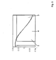
- den Verlauf des Mittelwertes der aufgezeichneten Signale für das Dämpfungsprofil für eine lokal erhöhte Dämpfung, entlang der Strecke zwischen den zwei Aktuatoren.
- Anhand von
Fig. 1 ist ein Körper 1 ersichtlich, der an zwei Positionen Aktuatoren 2, 3 für die Schwingungen 5, 6 aufweist und zwischen diesen Aktuatoren 2, 3 ein Sensor 4 positioniert ist. Beide Aktuatoren 2, 3 senden jeweils eine Schwingung 5, 6 aus, die dabei entstehende, stehende Welle 7 wird vom Sensor 4 gemessen. - In einem Körper 1 aus in einer Polymermatrix eingebetteten Glasfasern sind zwei positionierte Aktuatoren 2 und 3 und ein Sensor 4 nach
Fig. 1 eingebracht, die auf den jeweilig anderen Aktuator eine mechanische Schwingung 5 und 6 gleicher Amplitude und Wellenlänge aussenden. Durch die Interferenz beider Wellen 5 und 6 entsteht eine stehende Welle 7 im Körper 1. - Ist in dem Körper 1 wie in Beispiel 2 eine Fehlstelle vorhanden, ist ein Schaden an der Leichtbaukomponente permittelt. So reiben beispielsweise bei Einsatz von Glafaserwerkstoffen, die geprüft werden sollen, bei Schwingungen gebrochene Glasfasern aneinander, erzeugen damit Wärme und erhöhen die Dämpfung an dieser Fehlstelle. Damit verändert sich der Schwingungsverlauf von 5 und 6 und somit resultieren auch von 7. Die ankommenden Schwingungen werden vom Sensor 3 aufgenommen und verarbeitet.
- Anhand dieser Dämpfung wird die fehlstelle rechentechnisch lokalisiert, indem die dissipierte Energie der stehenden Welle 7 gewichtet wird. Aus dieser Angabe können wiederum eine Abschätzung des Schädigungszustandes und der Ort der Schädigung des Körpers 1 erfolgen.
- Anhand von
Fig. 2 wird eine gleichmäßige Verteilung der Dämpfung entlang der Strecke zwischen den Aktuatoren 2 und 3 mit dem Aufbau ausFig. 1 ersichtlich. - Zwei Schwingungen 5 und 6 werden von den Aktuatoren 2 und 3 angeregt, die Leichtbaukomponente weist keine Fehlstelle auf, die Dämpfung verläuft gleichmäßig, die aufgenommenen Signale des Sensors 4 werden im Diagramm der
Figur 3 dargestellt. - Anhand von
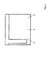
Fig. 4 wird eine lokal erhöhte Dämpfung entlang der Strecke zwischen den Aktuatoren 2 und 3 mit dem Aufbau ausFig. 1 ersichtlich. - Zwei Schwingungen 5 und 6 werden von den Aktuatoren, 2 und 3 angeregt, der Körper weist eine Fehlstelle auf, wodurch die lokale Dämpfung hervorgerufen wird. Die aufgenommenen Signale des Sensors 4 werden im Diagramm der
Figur 5 dargestellt. - In einem Körper 1 aus in einer Polymermatrix eingebetteten Glasfasern sind zwei positionierte Aktuatoren 2 und 3 und ein Sensor 4 nach
Fig. 1 eingebracht, die auf den jeweilig anderen Aktuator eine mechanische Schwingung 5 und 6 aussenden. Die Anfangsphase und -amplitude der propagierenden Schwingungen 5 und 6 werden stufenles verändert, so dass sich die Position des Wellenbauches auf Höhe des Sensors 4 befindet. -
- 1
- Leichtbaukomponente
- 2
- Aktuator
- 3
- Aktuator
- 4
- Sensor
- 5
- propagierende Schwingung ausgehend vom Aktuator 2
- 6
- propagierende Schwingung ausgehend vom Aktuator 3
- 7
- erzeugte stehende Welle
Claims (7)
- Verfahren zur Messung lokaler Werkstoffdämpfung, die insbesondere bei der Inspektion, Wartung oder Instand-haltung von Leichtbaukomponenten die Werkstoffe mit hohen mechanische Anforderungen aufweisen wie der Außenhaut von Flugkörpern, dadurch gekennzeichnet, dass mindestens eine Schwingung (5 oder 6) in einer Leichtbaukomponente (1) erzeugt, gemesson und eine Dämpfung im zu prüfenden Werkstoff mit Orts- und Richtungsauflösung bestimmt wird.
- Verfahren nach Anspruch 1, dadurch gekennzeichnet, dass zwei Schwingungen (5, 6) in einem Körper (1) erzeugt, gemessen und die Dämpfung im zu prüfenden Werkstoff der Leichtbaukomponente (1) mit Orts- und Richtungsauflösung bestimmt wird.
- Verfahren nach Anspruch 1 und 2, dadurch gekennzeichnet, dass als Werkstoff der Leichtbaukomponente (1) ein Kunststoffmaterial verwendet wird.
- Verfahren nach Anspruch 3, dadurch gekennzeichnet, dass als Kunststoffmaterial ein kohlenstofffaserverstärktes Kunststoffmaterial oder glasfaserverstärktes Kunststoff-material verwendet wird.
- Verfahren nach Anspruch 1 und wenigstens einem der An-sprüche 2 bis 4, dadurch gekennzeichnet, dass mindestens eine Schwingung (5 oder 6) von einem Sensor (4) in oder an der Leichtbaukomponente (1) gemessen wird und die mindestens eine erzeugte Schwingung (5 oder 6) so modifiziert wird, dass eine stehende Welle (7) entsteht, die der Sensor (4) misst.
- Verfahren nach Anspruch 1 und wenigstens einem der Ansprüche 2 bis 5, dadurch gekennzeichnet, dass eine rechentechnische Einrichtung einen Menswert des Sensors (4) auswertet und den Ort, die Richtung und/oder die Intensität einer Schädigung des zu prüfenden Werkstoffes in oder an der Leichtbaukomponente (1) errechnet.
- Verfahren nach Anspruch 1 und wenigstens einem der Ansprüche 2 bis 6, dadurch-gekennzeichnet, dass ein Sensor (4) örtlich zwischen Aktuatoren (2, 3) wirkt.
Applications Claiming Priority (1)
| Application Number | Priority Date | Filing Date | Title |
|---|---|---|---|
| DE102012011927 | 2012-06-13 |
Publications (3)
| Publication Number | Publication Date |
|---|---|
| EP2696184A2 true EP2696184A2 (de) | 2014-02-12 |
| EP2696184A3 EP2696184A3 (de) | 2016-11-02 |
| EP2696184B1 EP2696184B1 (de) | 2019-10-23 |
Family
ID=48672319
Family Applications (1)
| Application Number | Title | Priority Date | Filing Date |
|---|---|---|---|
| EP13002859.0A Active EP2696184B1 (de) | 2012-06-13 | 2013-06-04 | Verfahren zur Identifikation lokaler Werkstoffdämpfung in Verbund-Strukturen |
Country Status (3)
| Country | Link |
|---|---|
| EP (1) | EP2696184B1 (de) |
| DE (1) | DE102013009287A1 (de) |
| DK (1) | DK2696184T3 (de) |
Family Cites Families (3)
| Publication number | Priority date | Publication date | Assignee | Title |
|---|---|---|---|---|
| US5814729A (en) * | 1996-09-09 | 1998-09-29 | Mcdonnell Douglas Corporation | System for in-situ delamination detection in composites |
| EP2404135A4 (de) * | 2009-03-05 | 2013-10-09 | Purdue Research Foundation | Schadensnachweis mit laservibrometrie |
| GB2475225A (en) * | 2009-10-30 | 2011-05-18 | Wayne Rudd | A method for monitoring and/or maintaining the condition of a structure such as a pipeline |
-
2013
- 2013-06-04 DE DE102013009287.6A patent/DE102013009287A1/de not_active Ceased
- 2013-06-04 EP EP13002859.0A patent/EP2696184B1/de active Active
- 2013-06-04 DK DK13002859.0T patent/DK2696184T3/da active
Non-Patent Citations (1)
| Title |
|---|
| LINDSAY, R.: "Spatial and Temporal Attenua- tion and Dispersion of Sound", THE JOURNAL OF THE ACOUSTI- CAL SOCIETY OF AMERICA, vol. 23, 1951, pages 628 |
Also Published As
| Publication number | Publication date |
|---|---|
| DE102013009287A1 (de) | 2014-03-20 |
| EP2696184A3 (de) | 2016-11-02 |
| DK2696184T3 (da) | 2020-01-27 |
| EP2696184B1 (de) | 2019-10-23 |
Similar Documents
| Publication | Publication Date | Title |
|---|---|---|
| EP2265920B1 (de) | Vorrichtung und verfahren zum erkennen von schäden an einer arbeitsmaschine | |
| EP2730906B1 (de) | Vorrichtung und Verfahren zur Zustandsüberwachung eines Wälzlagers | |
| EP2478346B1 (de) | Verfahren und vorrichtung zur überwachung des fahrverhaltens eines schienenfahrzeugs | |
| EP1764589B1 (de) | Verfahren zur Prüfung eines Coriolis-Massendurchflussmessgeräts | |
| WO2011138027A1 (de) | Verfahren und vorrichtung zur zerstörungsfreien materialuntersuchung mittels ultraschall | |
| EP3899486B1 (de) | Vorrichtung und verfahren zur ermittlung mechanischer eigenschaften eines prüfkörpers | |
| EP3661829B1 (de) | Verfahren zum ermitteln einer stellkraft eines weichenantriebs basierend auf schallemissionsmessungen und weichenantriebssystem | |
| DE102020108182A1 (de) | Oberflächenmessgerät | |
| DE102018131948B4 (de) | Verfahren und Vorrichtung zum Detektieren eines Schlagereignisses sowie ein Fahrzeug hierzu | |
| DE102014103231B4 (de) | Kugel-Testvorrichtung und Verfahren zur Untersuchung von Schmierstoffen und/ oder von Reib- bzw. Verschleißprozessen | |
| DE102016202340A1 (de) | Messvorrichtung und Messverfahren | |
| DE102012000603A1 (de) | Verfahren zum Delektieren einer möglichen Beschädigung eines Kraftwagenbauteils | |
| EP2696184B1 (de) | Verfahren zur Identifikation lokaler Werkstoffdämpfung in Verbund-Strukturen | |
| DE102019209495A1 (de) | Verfahren zum Überprüfen einer Schaufel eines Triebwerks und Überprüfungsvorrichtung zum Überprüfen einer Schaufel eines Triebwerks | |
| EP2601490A1 (de) | VERFAHREN ZUR ÜBERWACHUNG VON ANTRIEBSKOMPONENTEN EINES GROßHYDRAULIKBAGGERS | |
| Figlus et al. | Evaluation of failure progress in glass-and jute-fibre reinforced polymer laminates by analysis of vibration and noise | |
| DE102015101942A1 (de) | Verfahren zur Prüfung eines aus einem Faserverbundwerkstoff hergestellten Bauteils | |
| EP2541541B1 (de) | Anordnung zur zerstörungsfreien Überwachung oder Prüfung von Bauteilen mittels Schallwellenanalyse | |
| DE10258335A1 (de) | Verfahren zur Untersuchung der Betriebsfestigkeit einer Kfz-Einrichtung auf einem Prüfstand | |
| DE102012109225A1 (de) | Laufrad zur Ermittlung des Schwingungsverhaltens von Laufradschaufeln, Prüfstand zur Ermittlung des Schwingungsverhaltens von Laufradschaufeln und ein Verfahren zur Ermittlung des Schwingungsverhaltens von Laufradschaufeln | |
| DE102020214594A1 (de) | Verfahren und Vorrichtung zur Ermittlung einer Werkstofffestigkeit eines Werkstoffs | |
| DE102019119820A1 (de) | Strukturbauteil aus faserverstärktem Kunststoff für ein Fahrzeug und Verfahren zur Schadensdiagnose eines solchen Strukturbauteils | |
| DE102014208681B4 (de) | Verfahren zur Überwachung eines Zustands eines in einem Fluid bewegten Rotorblatts | |
| DE102015114855A1 (de) | Verfahren zur Erfassung von Schädigungen eines Kunststoff-Metall- oder Metall-Metall-Verbundbauteils | |
| DE19647792A1 (de) | Vorrichtung und Verfahren zur Körperschall-Güteprüfung |
Legal Events
| Date | Code | Title | Description |
|---|---|---|---|
| AK | Designated contracting states |
Kind code of ref document: A2 Designated state(s): AL AT BE BG CH CY CZ DE DK EE ES FI FR GB GR HR HU IE IS IT LI LT LU LV MC MK MT NL NO PL PT RO RS SE SI SK SM TR |
|
| AX | Request for extension of the european patent |
Extension state: BA ME |
|
| PUAI | Public reference made under article 153(3) epc to a published international application that has entered the european phase |
Free format text: ORIGINAL CODE: 0009012 |
|
| PUAL | Search report despatched |
Free format text: ORIGINAL CODE: 0009013 |
|
| AK | Designated contracting states |
Kind code of ref document: A3 Designated state(s): AL AT BE BG CH CY CZ DE DK EE ES FI FR GB GR HR HU IE IS IT LI LT LU LV MC MK MT NL NO PL PT RO RS SE SI SK SM TR |
|
| AX | Request for extension of the european patent |
Extension state: BA ME |
|
| RIC1 | Information provided on ipc code assigned before grant |
Ipc: G01M 5/00 20060101AFI20160926BHEP Ipc: G01N 29/11 20060101ALI20160926BHEP Ipc: G01N 29/24 20060101ALI20160926BHEP Ipc: G01M 7/00 20060101ALI20160926BHEP Ipc: G01N 29/04 20060101ALI20160926BHEP |
|
| 17P | Request for examination filed |
Effective date: 20170428 |
|
| RBV | Designated contracting states (corrected) |
Designated state(s): AL AT BE BG CH CY CZ DE DK EE ES FI FR GB GR HR HU IE IS IT LI LT LU LV MC MK MT NL NO PL PT RO RS SE SI SK SM TR |
|
| STAA | Information on the status of an ep patent application or granted ep patent |
Free format text: STATUS: REQUEST FOR EXAMINATION WAS MADE |
|
| STAA | Information on the status of an ep patent application or granted ep patent |
Free format text: STATUS: EXAMINATION IS IN PROGRESS |
|
| 17Q | First examination report despatched |
Effective date: 20180208 |
|
| GRAP | Despatch of communication of intention to grant a patent |
Free format text: ORIGINAL CODE: EPIDOSNIGR1 |
|
| STAA | Information on the status of an ep patent application or granted ep patent |
Free format text: STATUS: GRANT OF PATENT IS INTENDED |
|
| INTG | Intention to grant announced |
Effective date: 20190529 |
|
| GRAS | Grant fee paid |
Free format text: ORIGINAL CODE: EPIDOSNIGR3 |
|
| GRAA | (expected) grant |
Free format text: ORIGINAL CODE: 0009210 |
|
| STAA | Information on the status of an ep patent application or granted ep patent |
Free format text: STATUS: THE PATENT HAS BEEN GRANTED |
|
| AK | Designated contracting states |
Kind code of ref document: B1 Designated state(s): AL AT BE BG CH CY CZ DE DK EE ES FI FR GB GR HR HU IE IS IT LI LT LU LV MC MK MT NL NO PL PT RO RS SE SI SK SM TR |
|
| REG | Reference to a national code |
Ref country code: GB Ref legal event code: FG4D Free format text: NOT ENGLISH |
|
| REG | Reference to a national code |
Ref country code: CH Ref legal event code: EP |
|
| REG | Reference to a national code |
Ref country code: IE Ref legal event code: FG4D Free format text: LANGUAGE OF EP DOCUMENT: GERMAN |
|
| REG | Reference to a national code |
Ref country code: DE Ref legal event code: R096 Ref document number: 502013013785 Country of ref document: DE |
|
| REG | Reference to a national code |
Ref country code: AT Ref legal event code: REF Ref document number: 1194186 Country of ref document: AT Kind code of ref document: T Effective date: 20191115 |
|
| REG | Reference to a national code |
Ref country code: DK Ref legal event code: T3 Effective date: 20200122 |
|
| REG | Reference to a national code |
Ref country code: NL Ref legal event code: MP Effective date: 20191023 |
|
| REG | Reference to a national code |
Ref country code: LT Ref legal event code: MG4D |
|
| PG25 | Lapsed in a contracting state [announced via postgrant information from national office to epo] |
Ref country code: SE Free format text: LAPSE BECAUSE OF FAILURE TO SUBMIT A TRANSLATION OF THE DESCRIPTION OR TO PAY THE FEE WITHIN THE PRESCRIBED TIME-LIMIT Effective date: 20191023 Ref country code: LV Free format text: LAPSE BECAUSE OF FAILURE TO SUBMIT A TRANSLATION OF THE DESCRIPTION OR TO PAY THE FEE WITHIN THE PRESCRIBED TIME-LIMIT Effective date: 20191023 Ref country code: NL Free format text: LAPSE BECAUSE OF FAILURE TO SUBMIT A TRANSLATION OF THE DESCRIPTION OR TO PAY THE FEE WITHIN THE PRESCRIBED TIME-LIMIT Effective date: 20191023 Ref country code: ES Free format text: LAPSE BECAUSE OF FAILURE TO SUBMIT A TRANSLATION OF THE DESCRIPTION OR TO PAY THE FEE WITHIN THE PRESCRIBED TIME-LIMIT Effective date: 20191023 Ref country code: LT Free format text: LAPSE BECAUSE OF FAILURE TO SUBMIT A TRANSLATION OF THE DESCRIPTION OR TO PAY THE FEE WITHIN THE PRESCRIBED TIME-LIMIT Effective date: 20191023 Ref country code: PT Free format text: LAPSE BECAUSE OF FAILURE TO SUBMIT A TRANSLATION OF THE DESCRIPTION OR TO PAY THE FEE WITHIN THE PRESCRIBED TIME-LIMIT Effective date: 20200224 Ref country code: FI Free format text: LAPSE BECAUSE OF FAILURE TO SUBMIT A TRANSLATION OF THE DESCRIPTION OR TO PAY THE FEE WITHIN THE PRESCRIBED TIME-LIMIT Effective date: 20191023 Ref country code: BG Free format text: LAPSE BECAUSE OF FAILURE TO SUBMIT A TRANSLATION OF THE DESCRIPTION OR TO PAY THE FEE WITHIN THE PRESCRIBED TIME-LIMIT Effective date: 20200123 Ref country code: GR Free format text: LAPSE BECAUSE OF FAILURE TO SUBMIT A TRANSLATION OF THE DESCRIPTION OR TO PAY THE FEE WITHIN THE PRESCRIBED TIME-LIMIT Effective date: 20200124 Ref country code: NO Free format text: LAPSE BECAUSE OF FAILURE TO SUBMIT A TRANSLATION OF THE DESCRIPTION OR TO PAY THE FEE WITHIN THE PRESCRIBED TIME-LIMIT Effective date: 20200123 Ref country code: PL Free format text: LAPSE BECAUSE OF FAILURE TO SUBMIT A TRANSLATION OF THE DESCRIPTION OR TO PAY THE FEE WITHIN THE PRESCRIBED TIME-LIMIT Effective date: 20191023 |
|
| PG25 | Lapsed in a contracting state [announced via postgrant information from national office to epo] |
Ref country code: IS Free format text: LAPSE BECAUSE OF FAILURE TO SUBMIT A TRANSLATION OF THE DESCRIPTION OR TO PAY THE FEE WITHIN THE PRESCRIBED TIME-LIMIT Effective date: 20200224 Ref country code: RS Free format text: LAPSE BECAUSE OF FAILURE TO SUBMIT A TRANSLATION OF THE DESCRIPTION OR TO PAY THE FEE WITHIN THE PRESCRIBED TIME-LIMIT Effective date: 20191023 Ref country code: HR Free format text: LAPSE BECAUSE OF FAILURE TO SUBMIT A TRANSLATION OF THE DESCRIPTION OR TO PAY THE FEE WITHIN THE PRESCRIBED TIME-LIMIT Effective date: 20191023 |
|
| PG25 | Lapsed in a contracting state [announced via postgrant information from national office to epo] |
Ref country code: AL Free format text: LAPSE BECAUSE OF FAILURE TO SUBMIT A TRANSLATION OF THE DESCRIPTION OR TO PAY THE FEE WITHIN THE PRESCRIBED TIME-LIMIT Effective date: 20191023 |
|
| REG | Reference to a national code |
Ref country code: DE Ref legal event code: R097 Ref document number: 502013013785 Country of ref document: DE |
|
| PG2D | Information on lapse in contracting state deleted |
Ref country code: IS |
|
| PG25 | Lapsed in a contracting state [announced via postgrant information from national office to epo] |
Ref country code: RO Free format text: LAPSE BECAUSE OF FAILURE TO SUBMIT A TRANSLATION OF THE DESCRIPTION OR TO PAY THE FEE WITHIN THE PRESCRIBED TIME-LIMIT Effective date: 20191023 Ref country code: CZ Free format text: LAPSE BECAUSE OF FAILURE TO SUBMIT A TRANSLATION OF THE DESCRIPTION OR TO PAY THE FEE WITHIN THE PRESCRIBED TIME-LIMIT Effective date: 20191023 Ref country code: EE Free format text: LAPSE BECAUSE OF FAILURE TO SUBMIT A TRANSLATION OF THE DESCRIPTION OR TO PAY THE FEE WITHIN THE PRESCRIBED TIME-LIMIT Effective date: 20191023 Ref country code: IS Free format text: LAPSE BECAUSE OF FAILURE TO SUBMIT A TRANSLATION OF THE DESCRIPTION OR TO PAY THE FEE WITHIN THE PRESCRIBED TIME-LIMIT Effective date: 20200223 |
|
| PGFP | Annual fee paid to national office [announced via postgrant information from national office to epo] |
Ref country code: FR Payment date: 20200623 Year of fee payment: 8 Ref country code: DK Payment date: 20200622 Year of fee payment: 8 Ref country code: DE Payment date: 20200623 Year of fee payment: 8 |
|
| PLBE | No opposition filed within time limit |
Free format text: ORIGINAL CODE: 0009261 |
|
| STAA | Information on the status of an ep patent application or granted ep patent |
Free format text: STATUS: NO OPPOSITION FILED WITHIN TIME LIMIT |
|
| PG25 | Lapsed in a contracting state [announced via postgrant information from national office to epo] |
Ref country code: IT Free format text: LAPSE BECAUSE OF FAILURE TO SUBMIT A TRANSLATION OF THE DESCRIPTION OR TO PAY THE FEE WITHIN THE PRESCRIBED TIME-LIMIT Effective date: 20191023 Ref country code: SK Free format text: LAPSE BECAUSE OF FAILURE TO SUBMIT A TRANSLATION OF THE DESCRIPTION OR TO PAY THE FEE WITHIN THE PRESCRIBED TIME-LIMIT Effective date: 20191023 Ref country code: SM Free format text: LAPSE BECAUSE OF FAILURE TO SUBMIT A TRANSLATION OF THE DESCRIPTION OR TO PAY THE FEE WITHIN THE PRESCRIBED TIME-LIMIT Effective date: 20191023 |
|
| 26N | No opposition filed |
Effective date: 20200724 |
|
| PGFP | Annual fee paid to national office [announced via postgrant information from national office to epo] |
Ref country code: AT Payment date: 20200618 Year of fee payment: 8 |
|
| PG25 | Lapsed in a contracting state [announced via postgrant information from national office to epo] |
Ref country code: SI Free format text: LAPSE BECAUSE OF FAILURE TO SUBMIT A TRANSLATION OF THE DESCRIPTION OR TO PAY THE FEE WITHIN THE PRESCRIBED TIME-LIMIT Effective date: 20191023 |
|
| PGFP | Annual fee paid to national office [announced via postgrant information from national office to epo] |
Ref country code: CH Payment date: 20200630 Year of fee payment: 8 |
|
| PG25 | Lapsed in a contracting state [announced via postgrant information from national office to epo] |
Ref country code: MC Free format text: LAPSE BECAUSE OF FAILURE TO SUBMIT A TRANSLATION OF THE DESCRIPTION OR TO PAY THE FEE WITHIN THE PRESCRIBED TIME-LIMIT Effective date: 20191023 |
|
| GBPC | Gb: european patent ceased through non-payment of renewal fee |
Effective date: 20200604 |
|
| PG25 | Lapsed in a contracting state [announced via postgrant information from national office to epo] |
Ref country code: LU Free format text: LAPSE BECAUSE OF NON-PAYMENT OF DUE FEES Effective date: 20200604 |
|
| REG | Reference to a national code |
Ref country code: BE Ref legal event code: MM Effective date: 20200630 |
|
| PG25 | Lapsed in a contracting state [announced via postgrant information from national office to epo] |
Ref country code: IE Free format text: LAPSE BECAUSE OF NON-PAYMENT OF DUE FEES Effective date: 20200604 Ref country code: GB Free format text: LAPSE BECAUSE OF NON-PAYMENT OF DUE FEES Effective date: 20200604 |
|
| PG25 | Lapsed in a contracting state [announced via postgrant information from national office to epo] |
Ref country code: BE Free format text: LAPSE BECAUSE OF NON-PAYMENT OF DUE FEES Effective date: 20200630 |
|
| REG | Reference to a national code |
Ref country code: DE Ref legal event code: R119 Ref document number: 502013013785 Country of ref document: DE |
|
| REG | Reference to a national code |
Ref country code: DK Ref legal event code: EBP Effective date: 20210630 |
|
| REG | Reference to a national code |
Ref country code: CH Ref legal event code: PL |
|
| REG | Reference to a national code |
Ref country code: AT Ref legal event code: MM01 Ref document number: 1194186 Country of ref document: AT Kind code of ref document: T Effective date: 20210604 |
|
| PG25 | Lapsed in a contracting state [announced via postgrant information from national office to epo] |
Ref country code: LI Free format text: LAPSE BECAUSE OF NON-PAYMENT OF DUE FEES Effective date: 20210630 Ref country code: DE Free format text: LAPSE BECAUSE OF NON-PAYMENT OF DUE FEES Effective date: 20220101 Ref country code: CH Free format text: LAPSE BECAUSE OF NON-PAYMENT OF DUE FEES Effective date: 20210630 Ref country code: AT Free format text: LAPSE BECAUSE OF NON-PAYMENT OF DUE FEES Effective date: 20210604 |
|
| PG25 | Lapsed in a contracting state [announced via postgrant information from national office to epo] |
Ref country code: TR Free format text: LAPSE BECAUSE OF FAILURE TO SUBMIT A TRANSLATION OF THE DESCRIPTION OR TO PAY THE FEE WITHIN THE PRESCRIBED TIME-LIMIT Effective date: 20191023 Ref country code: MT Free format text: LAPSE BECAUSE OF FAILURE TO SUBMIT A TRANSLATION OF THE DESCRIPTION OR TO PAY THE FEE WITHIN THE PRESCRIBED TIME-LIMIT Effective date: 20191023 Ref country code: FR Free format text: LAPSE BECAUSE OF NON-PAYMENT OF DUE FEES Effective date: 20210630 Ref country code: CY Free format text: LAPSE BECAUSE OF FAILURE TO SUBMIT A TRANSLATION OF THE DESCRIPTION OR TO PAY THE FEE WITHIN THE PRESCRIBED TIME-LIMIT Effective date: 20191023 |
|
| PG25 | Lapsed in a contracting state [announced via postgrant information from national office to epo] |
Ref country code: MK Free format text: LAPSE BECAUSE OF FAILURE TO SUBMIT A TRANSLATION OF THE DESCRIPTION OR TO PAY THE FEE WITHIN THE PRESCRIBED TIME-LIMIT Effective date: 20191023 |
|
| PG25 | Lapsed in a contracting state [announced via postgrant information from national office to epo] |
Ref country code: DK Free format text: LAPSE BECAUSE OF NON-PAYMENT OF DUE FEES Effective date: 20210630 |