EP2696159A1 - Échangeur thermique et procédé de mise en réseau d'échangeurs thermiques - Google Patents
Échangeur thermique et procédé de mise en réseau d'échangeurs thermiques Download PDFInfo
- Publication number
- EP2696159A1 EP2696159A1 EP13175842.7A EP13175842A EP2696159A1 EP 2696159 A1 EP2696159 A1 EP 2696159A1 EP 13175842 A EP13175842 A EP 13175842A EP 2696159 A1 EP2696159 A1 EP 2696159A1
- Authority
- EP
- European Patent Office
- Prior art keywords
- module
- heat exchanger
- wetting
- fluid medium
- wetting device
- Prior art date
- Legal status (The legal status is an assumption and is not a legal conclusion. Google has not performed a legal analysis and makes no representation as to the accuracy of the status listed.)
- Granted
Links
- 238000009736 wetting Methods 0.000 title claims abstract description 114
- 238000000034 method Methods 0.000 title claims abstract description 11
- XLYOFNOQVPJJNP-UHFFFAOYSA-N water Substances O XLYOFNOQVPJJNP-UHFFFAOYSA-N 0.000 claims abstract description 10
- 239000012530 fluid Substances 0.000 claims description 62
- 238000001816 cooling Methods 0.000 claims description 23
- 238000005057 refrigeration Methods 0.000 claims description 6
- 238000010438 heat treatment Methods 0.000 claims description 3
- 238000005507 spraying Methods 0.000 abstract description 7
- 230000000903 blocking effect Effects 0.000 abstract 3
- 238000012546 transfer Methods 0.000 description 28
- 239000003570 air Substances 0.000 description 26
- 239000007921 spray Substances 0.000 description 19
- 239000007788 liquid Substances 0.000 description 15
- 238000009423 ventilation Methods 0.000 description 6
- 229910052782 aluminium Inorganic materials 0.000 description 5
- XAGFODPZIPBFFR-UHFFFAOYSA-N aluminium Chemical compound [Al] XAGFODPZIPBFFR-UHFFFAOYSA-N 0.000 description 5
- 238000007710 freezing Methods 0.000 description 5
- 230000008014 freezing Effects 0.000 description 5
- 239000000463 material Substances 0.000 description 5
- 235000013305 food Nutrition 0.000 description 4
- 238000003860 storage Methods 0.000 description 4
- 239000012080 ambient air Substances 0.000 description 3
- 238000013459 approach Methods 0.000 description 3
- 238000010586 diagram Methods 0.000 description 3
- 230000001105 regulatory effect Effects 0.000 description 3
- 239000000126 substance Substances 0.000 description 3
- 229910000838 Al alloy Inorganic materials 0.000 description 2
- 241000446313 Lamella Species 0.000 description 2
- 239000004020 conductor Substances 0.000 description 2
- 238000010276 construction Methods 0.000 description 2
- 230000007797 corrosion Effects 0.000 description 2
- 238000005260 corrosion Methods 0.000 description 2
- 238000013461 design Methods 0.000 description 2
- 238000009826 distribution Methods 0.000 description 2
- 238000001704 evaporation Methods 0.000 description 2
- 230000005484 gravity Effects 0.000 description 2
- 230000007774 longterm Effects 0.000 description 2
- 238000012423 maintenance Methods 0.000 description 2
- 239000003507 refrigerant Substances 0.000 description 2
- 238000005476 soldering Methods 0.000 description 2
- 235000013311 vegetables Nutrition 0.000 description 2
- 241000251468 Actinopterygii Species 0.000 description 1
- RYGMFSIKBFXOCR-UHFFFAOYSA-N Copper Chemical compound [Cu] RYGMFSIKBFXOCR-UHFFFAOYSA-N 0.000 description 1
- 241000196324 Embryophyta Species 0.000 description 1
- 240000005561 Musa balbisiana Species 0.000 description 1
- 235000018290 Musa x paradisiaca Nutrition 0.000 description 1
- 239000004480 active ingredient Substances 0.000 description 1
- 235000015173 baked goods and baking mixes Nutrition 0.000 description 1
- 235000013361 beverage Nutrition 0.000 description 1
- 238000004140 cleaning Methods 0.000 description 1
- 239000012459 cleaning agent Substances 0.000 description 1
- 238000004891 communication Methods 0.000 description 1
- 235000009508 confectionery Nutrition 0.000 description 1
- 238000009749 continuous casting Methods 0.000 description 1
- 239000002826 coolant Substances 0.000 description 1
- 229910052802 copper Inorganic materials 0.000 description 1
- 239000010949 copper Substances 0.000 description 1
- 235000013365 dairy product Nutrition 0.000 description 1
- 230000001419 dependent effect Effects 0.000 description 1
- 235000013399 edible fruits Nutrition 0.000 description 1
- 230000000694 effects Effects 0.000 description 1
- 230000008020 evaporation Effects 0.000 description 1
- 238000004880 explosion Methods 0.000 description 1
- 235000019688 fish Nutrition 0.000 description 1
- 238000004108 freeze drying Methods 0.000 description 1
- 235000021022 fresh fruits Nutrition 0.000 description 1
- 238000012432 intermediate storage Methods 0.000 description 1
- 238000004519 manufacturing process Methods 0.000 description 1
- 235000013372 meat Nutrition 0.000 description 1
- 229910052751 metal Inorganic materials 0.000 description 1
- 239000002184 metal Substances 0.000 description 1
- 238000005457 optimization Methods 0.000 description 1
- 235000015927 pasta Nutrition 0.000 description 1
- 230000005070 ripening Effects 0.000 description 1
- 229910000679 solder Inorganic materials 0.000 description 1
Images


Classifications
-
- F—MECHANICAL ENGINEERING; LIGHTING; HEATING; WEAPONS; BLASTING
- F28—HEAT EXCHANGE IN GENERAL
- F28F—DETAILS OF HEAT-EXCHANGE AND HEAT-TRANSFER APPARATUS, OF GENERAL APPLICATION
- F28F1/00—Tubular elements; Assemblies of tubular elements
-
- F—MECHANICAL ENGINEERING; LIGHTING; HEATING; WEAPONS; BLASTING
- F28—HEAT EXCHANGE IN GENERAL
- F28F—DETAILS OF HEAT-EXCHANGE AND HEAT-TRANSFER APPARATUS, OF GENERAL APPLICATION
- F28F25/00—Component parts of trickle coolers
- F28F25/02—Component parts of trickle coolers for distributing, circulating, and accumulating liquid
-
- F—MECHANICAL ENGINEERING; LIGHTING; HEATING; WEAPONS; BLASTING
- F25—REFRIGERATION OR COOLING; COMBINED HEATING AND REFRIGERATION SYSTEMS; HEAT PUMP SYSTEMS; MANUFACTURE OR STORAGE OF ICE; LIQUEFACTION SOLIDIFICATION OF GASES
- F25B—REFRIGERATION MACHINES, PLANTS OR SYSTEMS; COMBINED HEATING AND REFRIGERATION SYSTEMS; HEAT PUMP SYSTEMS
- F25B2313/00—Compression machines, plants or systems with reversible cycle not otherwise provided for
- F25B2313/004—Outdoor unit with water as a heat sink or heat source
-
- F—MECHANICAL ENGINEERING; LIGHTING; HEATING; WEAPONS; BLASTING
- F25—REFRIGERATION OR COOLING; COMBINED HEATING AND REFRIGERATION SYSTEMS; HEAT PUMP SYSTEMS; MANUFACTURE OR STORAGE OF ICE; LIQUEFACTION SOLIDIFICATION OF GASES
- F25B—REFRIGERATION MACHINES, PLANTS OR SYSTEMS; COMBINED HEATING AND REFRIGERATION SYSTEMS; HEAT PUMP SYSTEMS
- F25B2339/00—Details of evaporators; Details of condensers
- F25B2339/04—Details of condensers
- F25B2339/041—Details of condensers of evaporative condensers
-
- F—MECHANICAL ENGINEERING; LIGHTING; HEATING; WEAPONS; BLASTING
- F28—HEAT EXCHANGE IN GENERAL
- F28D—HEAT-EXCHANGE APPARATUS, NOT PROVIDED FOR IN ANOTHER SUBCLASS, IN WHICH THE HEAT-EXCHANGE MEDIA DO NOT COME INTO DIRECT CONTACT
- F28D1/00—Heat-exchange apparatus having stationary conduit assemblies for one heat-exchange medium only, the media being in contact with different sides of the conduit wall, in which the other heat-exchange medium is a large body of fluid, e.g. domestic or motor car radiators
-
- F—MECHANICAL ENGINEERING; LIGHTING; HEATING; WEAPONS; BLASTING
- F28—HEAT EXCHANGE IN GENERAL
- F28D—HEAT-EXCHANGE APPARATUS, NOT PROVIDED FOR IN ANOTHER SUBCLASS, IN WHICH THE HEAT-EXCHANGE MEDIA DO NOT COME INTO DIRECT CONTACT
- F28D5/00—Heat-exchange apparatus having stationary conduit assemblies for one heat-exchange medium only, the media being in contact with different sides of the conduit wall, using the cooling effect of natural or forced evaporation
-
- F—MECHANICAL ENGINEERING; LIGHTING; HEATING; WEAPONS; BLASTING
- F28—HEAT EXCHANGE IN GENERAL
- F28F—DETAILS OF HEAT-EXCHANGE AND HEAT-TRANSFER APPARATUS, OF GENERAL APPLICATION
- F28F2250/00—Arrangements for modifying the flow of the heat exchange media, e.g. flow guiding means; Particular flow patterns
- F28F2250/08—Fluid driving means, e.g. pumps, fans
-
- F—MECHANICAL ENGINEERING; LIGHTING; HEATING; WEAPONS; BLASTING
- F28—HEAT EXCHANGE IN GENERAL
- F28F—DETAILS OF HEAT-EXCHANGE AND HEAT-TRANSFER APPARATUS, OF GENERAL APPLICATION
- F28F27/00—Control arrangements or safety devices specially adapted for heat-exchange or heat-transfer apparatus
- F28F27/02—Control arrangements or safety devices specially adapted for heat-exchange or heat-transfer apparatus for controlling the distribution of heat-exchange media between different channels
-
- Y—GENERAL TAGGING OF NEW TECHNOLOGICAL DEVELOPMENTS; GENERAL TAGGING OF CROSS-SECTIONAL TECHNOLOGIES SPANNING OVER SEVERAL SECTIONS OF THE IPC; TECHNICAL SUBJECTS COVERED BY FORMER USPC CROSS-REFERENCE ART COLLECTIONS [XRACs] AND DIGESTS
- Y02—TECHNOLOGIES OR APPLICATIONS FOR MITIGATION OR ADAPTATION AGAINST CLIMATE CHANGE
- Y02B—CLIMATE CHANGE MITIGATION TECHNOLOGIES RELATED TO BUILDINGS, e.g. HOUSING, HOUSE APPLIANCES OR RELATED END-USER APPLICATIONS
- Y02B30/00—Energy efficient heating, ventilation or air conditioning [HVAC]
- Y02B30/62—Absorption based systems
Definitions
- the invention relates to a heat exchanger comprising at least a first module and a second module for the heat exchange between a first fluid medium and a second fluid medium, wherein the first fluid medium through a closed channel system separately from the second fluid medium is feasible.
- the closed channel system can be flowed around by the second fluid medium, wherein the second fluid medium is gaseous.
- a wetting device is provided, by means of which the second fluid medium is wettable with a third fluid medium.
- the invention further relates to the use of a provided with a wetting device heat exchanger in a refrigeration system for room cooling or recooling.
- a heat exchanger can be used in the food industry, the chemical industry, the pharmaceutical industry or in the cooling or freezing of products.
- the invention also relates to a method for wetting a heat exchanger, comprising at least a first module and a second module for the heat exchange between a first fluid medium and a second fluid medium, wherein the first fluid medium is guided by a closed channel system separate from the second fluid medium , wherein the closed channel system is flowed around by the second fluid medium, wherein the second fluid medium is gaseous.
- a third fluid medium wets the second fluid medium or heat exchanger by means of a wetting device.
- a wetting of the heat exchanger can be provided, such as in W02010 / 040635 A1 is disclosed.
- This document shows a laminated heat exchanger, which in the simplest case consists of a tube for the passage of a heat transfer medium and a plurality of fins, which are connected to the tube and in operation are in communication with a second medium.
- This construction is particularly useful when the second medium is gaseous and, for example, consists of ambient air, since this is a comparatively low Has heat transfer coefficients, which can be compensated by a correspondingly large surface of the slats.
- the laminated heat exchanger may also contain a plurality of tubes for more than one heat transfer medium, or the tubes may be connected in parallel and / or in series as needed.
- the heat transfer rate and the efficiency are essentially determined by the temperature difference between the lamellae on the one hand and the one or more tubes.
- the temperature difference is the smaller, the greater the conductivity and the thickness of the lamella and the smaller the mutual distance of the tubes. Therefore, so-called microchannel heat transfer elements have been used for some years. These may for example be designed as an extruded profile, which is made of a material with good thermal conductivity, such as aluminum.
- the microchannel heat transfer elements include a plurality of channels having a diameter usually in the range of 0.5 to 3 mm for the heat transfer medium. Instead of small tubes, aluminum continuous casting profiles are preferably used in the microchannel heat transfer element.
- the object of the invention is to improve the efficiency of a heat exchanger comprising at least two modules.
- a heat exchanger comprising at least a first module (2) and a second module (12, 22, 32, 42, 52, 62, 72) for the heat exchange between a first fluid medium and a second fluid medium, wherein the first fluid medium separated by a closed channel system (3) from the second fluid Medium is feasible, wherein the closed channel system of the second fluid medium can flow around and the second fluid medium is gaseous.
- a first wetting device for the first module and a second wetting device for the second module is provided, by means of which the first module and the second module are wettable with a third fluid medium, wherein the first wetting device for the first module independently of the wetting device is operable for the second module.
- the second fluid medium or the heat exchanger or the closed channel system is wetted with a third fluid medium. Accordingly, if it is a spraying device, a third fluid medium can be sprayed into the second fluid medium or to the heat exchanger or the closed channel system.
- a third fluid medium can be sprayed into the second fluid medium or to the heat exchanger or the closed channel system.
- more than two modules can be provided. If a plurality of modules is provided, in particular at least 8 modules, it can also be provided that the wetting devices of two modules in each case are jointly controlled in pairs, that is to say that the supply of third medium to the modules connected in pairs takes place together.
- the heat exchangers according to the invention have the advantage that thanks to the wetting device, which can be separately or individually connected for each module, the cooling capacity can be specifically adapted to the requirements, so that exactly the required cooling capacity is delivered by means of a temperature control.
- the cooling capacity By wetting the cooling capacity is increased at a given total exchange area of the modules and at a given flow rate of the second medium, the cooling capacity compared to a heat exchanger without wetting device or reduced for a given cooling capacity, the total exchange area of all modules.
- the efficiency of the heat exchanger is thus increased by the wetting device and optimized by the ability to selectively control the wetting devices of each individual module.
- a major advantage of the heat exchanger according to the invention is the avoidance of a sudden increase in performance at the onset of wetting, just at the time when the wetting device is switched on.
- the heat exchanger is not wetted over the entire surface, for example sprayed, with the result that the performance as a result of wetting increases sharply, since the heat exchange over the total exchange area of all modules is increased simultaneously.
- the control of the heat exchanger can thus over the prior art be improved overall, because with the inventive solution, a higher precision of the control is possible, which was previously not possible for the solution according to the prior art.
- third medium ie in particular the spray liquid result.
- the in W02010 / 040635 A1 described solution can be saved up to 95% of the third medium, wherein the duration of wetting is the same.
- the selective use of wetting devices increases their service life and the life of the heat exchanger.
- wetting devices can lead to corrosion phenomena on the heat exchanger, which can lead to damage if the wetting device is operated for too long. Therefore, so far the annual service life of wetting devices has been limited. If the wetting devices can be connected independently of one another, in particular can be switched on sequentially, the annual service life can thus be extended overall.
- a module of the heat exchanger is understood to be a chamber detected by a ventilator.
- each module is sequential, that is, individual modules are wetted in succession with the third medium.
- the regulation ensures that the time period for each individual module is substantially the same length, that is, that the spraying time periods for each module are substantially the same length.
- the solution according to the invention can be used with advantage as long as the wetting devices can be controlled independently of one another for at least half of the modules. Interconnected modules then form so-called module groups. Modules can be advantageously combined into module groups if the total number of modules is greater than four.
- the first medium may be, for example, a liquid refrigerant or heat carrier or an evaporating or condensing heat medium.
- heat means is to be understood as meaning any fluid which can be advantageously used in a heat exchanger.
- heating means thus includes both the known refrigerant and any other suitable heat transfer medium, in particular a coolant.
- the second medium is the surrounding medium which is outside the closed channel system of the heat exchanger.
- This second medium may be in the liquid state, for example water, oil or else in the gaseous state, ie in particular ambient air or contained. Heat can be absorbed by the second medium or heat can be transferred to the second medium so that it cools or heats up.
- a first shut-off element for the first wetting device and a second shut-off element for the second wetting device is provided.
- the shut-off element may comprise at least one actuatable by a solenoid valve, a hydraulically actuated valve, a pneumatically actuated valve or a pump.
- a control system can be provided, by means of which the useful life of each of the shut-off elements can be detected, so that the shut-off elements can be activated based on data on the service life.
- the control system may comprise a memory unit in which the duration of the individual wetting is stored for each module, so that the total useful life and the sum of wetting per module can be calculated and is comparable to a total useful life. Maintenance intervals can also be programmed with this control system, so that maintenance of the heat exchanger or each of the modules can be carried out individually when a specific service life has been reached.
- the first wetting device can be switched over by a time period offset to the second wetting device.
- a time period offset to the second wetting device.
- the control system automatically adds the individual useful lives of each wetting device to a total useful life of the respective wetting device.
- the closed channel system may comprise at least one pipe system, a system of fins or a system of plates for receiving the first fluid medium.
- the closed channel system may be formed as a laminated tubular heat exchanger, which according to one example in the W02011 / 034444 A1 disclosed method is made.
- the slats are punched with a press and a special tool and put into packages.
- tubes are inserted between each two adjacent lamellae. These tubes are then widened mechanically or hydraulically, so that a very good contact and thus a good heat transfer between the tube and lamella arises.
- the tubes which traverse the lamellae are connected at their ends by arcs with each other or connected together by a collection and distribution pipe, for example by soldering.
- the first module and the second module of the heat exchanger are designed such that the closed channel system can be wetted directly by means of the first wetting device and / or the second wetting device.
- the channel system is arranged at an inclination angle to the vertical direction.
- a module with microchannel heat transfer elements has in the W02010 / 040635 A1 proposed arrangement in which a plurality of microchannel heat transfer elements and a plurality of heat exchange ribs are provided, which are thermally conductively connected together. Through the heat exchange ribs Air ducts are formed. The air in the air ducts is kept in motion by a ventilation device.
- This heat exchanger assembly comprises a wetting device for wetting the closed channel system comprising at least one pipe system, a system of fins or a system of plates for receiving the first fluid medium, in particular microchannel heat transfer elements and / or heat exchange fins, with liquid, for example water ,
- the modules are arranged at an angle of inclination with respect to the vertical, ie the vertical direction.
- the angle is determined by the fact that, in operation, gravity and / or inertial forces acting on droplets of liquid on or in a heat exchanger module are in equilibrium with the buoyancy forces of the airflow.
- the angle with respect to the vertical direction is in the range of at least 10 ° to and at 40 °, preferably in the range of at least 15 ° to and 30 °.
- the microchannel heat transfer elements may also be arranged in their longitudinal direction at an angle to the vertical direction. The angle may coincide with the angle of inclination of the heat exchanger module in which they are contained.
- the modules have a lower side and an upper side, in particular if they are inclined relative to the vertical direction.
- a ventilation device is provided to generate in the air ducts an air flow from the bottom to the top.
- the wetting device is provided to wet the microchannel heat transfer elements and / or the heat exchange fins from the bottom or the top.
- the wetting device may be configured such that the microchannel heat transfer elements and / or the heat exchange fins are wetted both from the bottom and from the top.
- the ventilation device can also generate an air flow from the top to the bottom in the air ducts.
- a temperature control may be provided for switching on each of the first or second wetting devices.
- the temperature control comprises a temperature measuring device, which detects the temperature of the second medium. If its temperature rises above a defined limit and if the second medium is to be cooled, one of the wetting devices is switched on by instructing the control system to open the corresponding shut-off element. If the temperature continues to increase, the control system issues the instruction to open another shut-off element for another module. Which of the shut-off is opened priority depends on the stored total useful life.
- the control system is preferably set such that first the shut-off element with the shortest total useful life is opened.
- the heat exchanger can additionally have a humidifying device arranged on the input side in the air flow for cooling the air and / or a drip catcher arranged on the output side in the air flow.
- a heat exchanger according to one of the preceding embodiments can be used in a refrigeration system for room cooling and / or recooling. Furthermore, a heat exchanger according to one of the preceding embodiments for cooling or freezing of products or for cooling of food, especially dairy products, beverages, baked goods, finished products, confectionery, vegetables, fruits or for freezing food, especially meat, fish, pasta or finished products or for freeze-drying.
- the storage of fresh fruits and vegetables requires a precise knowledge of the specific properties of the products.
- the requirements for temperature, humidity and air flow must be adapted to the product to be stored.
- the heat exchangers are used here for long-term storage, intermediate storage or for maturing processes, for example banana ripening plants.
- a heat exchanger can be used both in the production of food, chemical substances or pharmaceutical active ingredients for the cooling of the products but also for the room cooling.
- the heat exchanger can also be used for long-term storage, for transfer warehouse or fresh storage, with a particularly important for these applications a uniform temperature distribution, high reliability and low operating costs play an important role.
- chemical products explosion protection, corrosion protection and special hygienic regulations can be of importance, so that a certain room temperature must be kept as precisely as possible.
- the performance of such an industrial refrigeration system can be done by high air velocities by using fans with external pressure, by special fin spacing or by an adapted air flow.
- a method of wetting a heat exchanger comprising at least a first module and a second module for heat exchange between a first fluid medium and a second fluid medium, wherein the first fluid medium is passed through a closed channel system separate from the second fluid medium, the closed channel system flows around the second fluid medium, wherein the second fluid medium is gaseous. Furthermore, a first wetting device for the first module and a second wetting device for the second module are provided, by means of which the first module and the second module are wetted with a third fluid medium, wherein the first wetting device for the first module independently of the wetting device for the second module is actuated.
- the inventive method for wetting a heat exchanger has, according to the device already described the advantage that thanks to the separate or individually switchable wetting device for each module, the cooling capacity can be adjusted specifically to the needs, so that by means of a temperature control exactly the required cooling capacity is delivered.
- wetting the cooling capacity is increased at a given total exchange area of the modules and at a given flow rate of the second medium, the cooling capacity compared to a heat exchanger without wetting device or reduced for a given cooling capacity, the total exchange area of all modules.
- the efficiency of the heat exchanger is thus increased by the wetting device and optimized by the ability to selectively control the wetting devices of each individual module.
- the first wetting device can be actuated simultaneously or with a time offset to the second wetting device, so that a local and thus sequential wetting of the first module can take place independently of the second module.
- the outlet temperature of the first fluid medium is measured out of the heat exchanger and, depending on the outlet temperature, at least one of the wetting devices is switched on or off.
- the temperature of the second medium can also be measured and a connection of each of the wetting devices can be made individually if the temperature of the second medium exceeds the permissible maximum temperature.
- each of the wetting devices may be registered by a control system and each of the Wetting devices depending on the previous service life can be switched on as needed.
- the speed of the air flow can also be regulated in such a way that no or at most a fixed quantity of drops can be entrained by the third medium, ie the liquid, present on a module by the air flow.
- the amount of liquid supplied for wetting the microchannel heat transfer elements and / or the heat exchange fins and the velocity of the air flow may be regulated such that the gravitational and / or inertial forces acting on or in a module are at drops of the third Medium act, in balance with the buoyancy forces of the air flow.
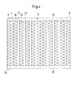
- the heat exchanger 1 according Fig. 1 has a wetting device.
- This heat exchanger 1 has a first module 2 and a second module to eighth module 12, 22, 32, 42, 52, 62, 72.
- Each of the modules is equipped with a ventilation device, such as a fan, to allow air to flow through the module.
- each module a heat exchange takes place between a first fluid medium and a second fluid medium.
- the first fluid medium is guided by a closed channel system 3 separate from the second fluid medium, so that the first medium does not come into contact with the second medium, which in Fig. 4 is shown.
- the closed channel system flows around the second fluid medium.
- the second fluid medium is gaseous.
- the closed channel system 3 contains a plurality of microchannel heat transfer elements 7, 17, 27 of which only three have been provided with reference numerals for the sake of clarity.
- the microchannel heat transfer elements 7, 17, 27 may for example be designed as flat tubes which are arranged parallel to one another.
- Adjacent microchannel heat transfer elements 7, 17, 27 are spaced apart and a plurality of heat exchange fins 8, 18, 28 are interposed and thermally conductively connected to the microchannel heat transfer elements 7, 17, 27, for example via a solder joint.
- the heat exchange ribs 8, 18, 28 air channels are formed in the in Fig. 2 shown module perpendicular to the image plane.
- the heat exchange fins are made from a folded sheet metal strip which may have a zigzag pattern.
- the microchannel heat transfer elements 7, 17, 27 may be designed as an extruded profile, which is made of a material with good thermal conductivity such as aluminum or an aluminum alloy.
- an inlet element 9 For supplying the second medium, an inlet element 9 is provided, which opens into an inlet collecting channel 10. From the inlet collection channel 10, the microchannel heat transfer elements 7, 17, 27 lead to the outlet collection channel 20, which opens into an outlet element 19.
- the individual parts of the module such as the microchannel heat transfer elements 7, 17, 27, the heat exchange ribs 8, 18, 28, the inlet and outlet collection channels 10, 20 and the inlet and outlet elements 9, 19 made of aluminum or an aluminum alloy and soldered the assembled parts together in a soldering oven.
- Fig. 1 shows a wetting apparatus 4 for the first module 2, and corresponding second to eighth wetting devices 14, 24, 34, 44, 54, 64, 74 for the second to eighth modules 12, 22, 32, 42, 52, 62, 72 all modules and all wetting devices are constructed substantially the same, is for the sake of simplicity only the wetting device 4 for the first module 2 are described in more detail, including on Fig. 5 should be referenced.
- Fig. 5 shows a section along the line AA of Fig. 1 ,
- the wetting device is equipped with spray nozzles 16 to wet the second fluid medium with a third fluid medium.
- the spray nozzle 16 may, for example, be a hollow cone nozzle, preferably a flat jet nozzle.
- the advantage of the flat jet nozzle is that they have a larger cross-section and thus fewer spray nozzles 16 are required.
- a more uniform spray pattern is produced by means of the flat jet nozzle than in hollow cone nozzles that prevents the complete evaporation of the water on the heat exchanger and thus the deposits form.
- the second medium is a gas, preferably ambient air.
- the third medium is preferably a liquid, in particular water.
- a first wetting device 4 is provided for the first module and a second wetting device 14 for the second module 12 and further wetting devices 24, 34, 44, 54, 64, 74 for each of the modules 22, 32, 42, 52, 62, 72.
- Each of the wetting devices for each module 2 is operable independently of the wetting device for each other module.
- modules are supplied in pairs by a wetting device, what in Fig. 5 is shown as a variant.
- Fig. 2 shows a wetting device according to the prior art.
- this heat exchanger 1 has a first module 2 and a second module to eighth module 12, 22, 32, 42, 52, 62, 72 on.
- Each of the modules is equipped with a ventilation device, such as a fan, to allow air to flow through the module.
- each module is equipped with a wetting device 4.
- this wetting device can only be controlled centrally by means of a single shut-off element 5. This means that in this case either all modules are sprayed or none of the modules.
- Fig. 3 shows a diagram in which the abscissa, the operating hours of the heat exchanger are plotted. On the ordinate the air temperature is plotted.
- the diagram illustrates the advantages of the invention in one embodiment. Due to the inventive solution, the dry design temperature of 31.2 ° C is lowered to 30.0 ° C, with the same conditions, the useful life of 50h / a is increased to 145 h / a.
- the general conditions were given as follows: 50h duration of spraying per module or 50 h duration of spraying per heat exchanger.
- Fig. 4 shows a possible construction of a module of a heat exchanger. On the subject of the Fig. 4 has already been discussed earlier.
- Fig. 5 shows a section through an arrangement of two opposite module pairs 2A, 2B of a module 2 of a heat exchanger 1, which shows various possibilities of arrangement of wetting devices 4, 4A, 4B, 4C, 4D.
- Each of the module pairs 2A, 2B may form an independent module, alternatively, the module 2 could be arranged in a ring around the centrally arranged air duct 11.
- a ventilation device 13 is provided, which sucks in air from the environment and passes through the air duct 11 therethrough.
- Each of the modules may be related to Fig. 4 described, be designed.
- each of the modules 2A and 2B includes an inclination angle to the vertical direction.
- This angle with respect to the vertical direction may be in the range of at least 10 ° to and at 40 °, preferably in the range of at least 15 ° to and 30 °.
- the angle is determined by the fact that, in operation, gravity and / or inertial forces acting on or in a module on drops of liquid forming the third medium are in equilibrium with the buoyancy forces of the air flow.
- the size and number of modules 2A, 3B is usually determined according to the required cooling capacity.
- the wetting device 4 consists of a conduit which feeds a plurality of spray nozzles 16 arranged one behind the other, of which only a single one is provided with a reference mark.
- the supply of liquid to the spray nozzles 16 can be prevented with the shut-off element 5.
- the wetting device 4A according to a in Fig. 5 variant shown, only a single spray nozzle 16 A can be arranged. The supply of liquid to the spray nozzle 16A can be prevented with the shut-off element 5A.
- a wetting device 4B with a spray nozzle 16B can accordingly be provided for the second module 2B, which can be regulated in the same way by means of the shutoff element 5B as is shown for the wetting device 4A.
- a wetting device 4C has, in analogy to the wetting device 4, a plurality of spray nozzles 16C, which are controllable together via the shut-off element 5C.
- the wetting device 4D can also be arranged in the air channel 11 between the two modules 2A and 2B.
- both module 2A and module 2B are simultaneously supplied with liquid by the spray nozzles 16D, 16E with the spray nozzles 16D directed toward module 2A and the spray nozzles 16E aligned toward module 2B.
- a shut-off element 5D controls the supply of liquid to both spray nozzles 16D and 16E together.
Landscapes
- Engineering & Computer Science (AREA)
- Physics & Mathematics (AREA)
- Thermal Sciences (AREA)
- Mechanical Engineering (AREA)
- General Engineering & Computer Science (AREA)
- Heat-Exchange Devices With Radiators And Conduit Assemblies (AREA)
Priority Applications (2)
| Application Number | Priority Date | Filing Date | Title |
|---|---|---|---|
| EP13175842.7A EP2696159B1 (fr) | 2012-08-09 | 2013-07-10 | Échangeur thermique et procédé de mise en réseau d'échangeurs thermiques |
| EP17172125.1A EP3249341B1 (fr) | 2012-08-09 | 2013-07-10 | Échangeur thermique et procédé de mise en réseau d'échangeurs thermiques |
Applications Claiming Priority (2)
| Application Number | Priority Date | Filing Date | Title |
|---|---|---|---|
| EP12179934 | 2012-08-09 | ||
| EP13175842.7A EP2696159B1 (fr) | 2012-08-09 | 2013-07-10 | Échangeur thermique et procédé de mise en réseau d'échangeurs thermiques |
Related Child Applications (2)
| Application Number | Title | Priority Date | Filing Date |
|---|---|---|---|
| EP17172125.1A Division EP3249341B1 (fr) | 2012-08-09 | 2013-07-10 | Échangeur thermique et procédé de mise en réseau d'échangeurs thermiques |
| EP17172125.1A Division-Into EP3249341B1 (fr) | 2012-08-09 | 2013-07-10 | Échangeur thermique et procédé de mise en réseau d'échangeurs thermiques |
Publications (2)
| Publication Number | Publication Date |
|---|---|
| EP2696159A1 true EP2696159A1 (fr) | 2014-02-12 |
| EP2696159B1 EP2696159B1 (fr) | 2017-08-30 |
Family
ID=46967914
Family Applications (2)
| Application Number | Title | Priority Date | Filing Date |
|---|---|---|---|
| EP13175842.7A Active EP2696159B1 (fr) | 2012-08-09 | 2013-07-10 | Échangeur thermique et procédé de mise en réseau d'échangeurs thermiques |
| EP17172125.1A Active EP3249341B1 (fr) | 2012-08-09 | 2013-07-10 | Échangeur thermique et procédé de mise en réseau d'échangeurs thermiques |
Family Applications After (1)
| Application Number | Title | Priority Date | Filing Date |
|---|---|---|---|
| EP17172125.1A Active EP3249341B1 (fr) | 2012-08-09 | 2013-07-10 | Échangeur thermique et procédé de mise en réseau d'échangeurs thermiques |
Country Status (5)
| Country | Link |
|---|---|
| US (2) | US10161689B2 (fr) |
| EP (2) | EP2696159B1 (fr) |
| DK (1) | DK2696159T3 (fr) |
| HU (1) | HUE035148T2 (fr) |
| MX (1) | MX345377B (fr) |
Cited By (2)
| Publication number | Priority date | Publication date | Assignee | Title |
|---|---|---|---|---|
| EP3671090B1 (fr) | 2018-12-17 | 2023-04-05 | Lu-Ve S.P.A. | Procédé de refroidissement amélioré et appareil pour la mise en uvre dudit procédé |
| WO2023214866A1 (fr) * | 2022-05-02 | 2023-11-09 | STRELITS-STRELE, Janis | Système de pré-refroidissement adiabatique pour échangeur de chaleur refroidi par air du type en v |
Families Citing this family (3)
| Publication number | Priority date | Publication date | Assignee | Title |
|---|---|---|---|---|
| PL3143358T3 (pl) | 2014-05-15 | 2021-08-02 | Frigel Firenze S.P.A. | Mieszany konwektor |
| US10365053B2 (en) * | 2016-04-11 | 2019-07-30 | Danny Billings | Apparatus and associated methods for cleaning HVAC systems |
| US20220390188A1 (en) * | 2021-06-08 | 2022-12-08 | Uniflair S.P.A. | Multi-stage water distribution system for cross-flow evaporative heat exchanger |
Citations (9)
| Publication number | Priority date | Publication date | Assignee | Title |
|---|---|---|---|---|
| US3384165A (en) * | 1966-02-03 | 1968-05-21 | Du Pont | Heat exchanger |
| GB1354607A (en) * | 1970-06-29 | 1974-06-05 | Baltimore Aircoil Co Inc | Injector type evaporative heat exchanger |
| DE2840317A1 (de) * | 1977-09-22 | 1979-04-05 | Munters Ab Carl | Einrichtung bei einem verdunstungskuehler |
| FR2724220A1 (fr) * | 1994-09-07 | 1996-03-08 | Electricite De France | Refrigerant atmospherique humide a dispositif antigel |
| CH693043A5 (de) * | 1998-05-11 | 2003-01-31 | Armin Schnetzler | Einrichtung zur Erhöhung der Kühlleistung eines Wärmetauschers. |
| WO2010040635A1 (fr) | 2008-10-08 | 2010-04-15 | A-Heat Allied Heat Exchange Technology Ag | Ensemble échangeur de chaleur et procédé pour faire fonctionner celui-ci |
| WO2011003444A1 (fr) | 2009-07-07 | 2011-01-13 | A-Heat Allied Heat Exchange Technology Ag | Système d'échange de chaleur et procédé d'utilisation d'un système d'échange de chaleur |
| WO2011034444A1 (fr) | 2009-09-17 | 2011-03-24 | Polygon (Nz) Limited | Formulations de tensioactifs herbicides |
| DE102010055449A1 (de) * | 2010-12-21 | 2012-06-21 | Linde Ag | Plattenwärmetauscher |
Family Cites Families (8)
| Publication number | Priority date | Publication date | Assignee | Title |
|---|---|---|---|---|
| SE311371B (fr) * | 1966-01-26 | 1969-06-09 | Munters C | |
| US4266406A (en) * | 1980-01-22 | 1981-05-12 | Frank Ellis | Cooling system for condenser coils |
| US4367787A (en) * | 1980-05-16 | 1983-01-11 | Haden Schweitzer Corporation | Air conditioning apparatus and method for paint spray booths |
| US5701748A (en) * | 1995-06-12 | 1997-12-30 | Phelps; Jack Leroy | Evaporative cooler for air conditioning condensing unit |
| US6070860A (en) * | 1998-08-14 | 2000-06-06 | The Marley Cooling Tower Company | Crossflow water cooling tower having structure allowing air flow through water distribution system |
| TW445360B (en) * | 2000-08-02 | 2001-07-11 | Nutec Electrical Eng Co Ltd | Air-conditioning apparatus with evaporative type condenser |
| US6823684B2 (en) * | 2002-02-08 | 2004-11-30 | Tim Allan Nygaard Jensen | System and method for cooling air |
| US7614613B2 (en) * | 2007-05-04 | 2009-11-10 | Equistar Chemicals, Lp | Method of operating a cooling fluid system |
-
2013
- 2013-07-10 EP EP13175842.7A patent/EP2696159B1/fr active Active
- 2013-07-10 HU HUE13175842A patent/HUE035148T2/en unknown
- 2013-07-10 DK DK13175842.7T patent/DK2696159T3/da active
- 2013-07-10 EP EP17172125.1A patent/EP3249341B1/fr active Active
- 2013-08-08 MX MX2013009156A patent/MX345377B/es active IP Right Grant
- 2013-08-09 US US13/964,029 patent/US10161689B2/en active Active
-
2018
- 2018-11-26 US US16/200,537 patent/US20190093961A1/en not_active Abandoned
Patent Citations (9)
| Publication number | Priority date | Publication date | Assignee | Title |
|---|---|---|---|---|
| US3384165A (en) * | 1966-02-03 | 1968-05-21 | Du Pont | Heat exchanger |
| GB1354607A (en) * | 1970-06-29 | 1974-06-05 | Baltimore Aircoil Co Inc | Injector type evaporative heat exchanger |
| DE2840317A1 (de) * | 1977-09-22 | 1979-04-05 | Munters Ab Carl | Einrichtung bei einem verdunstungskuehler |
| FR2724220A1 (fr) * | 1994-09-07 | 1996-03-08 | Electricite De France | Refrigerant atmospherique humide a dispositif antigel |
| CH693043A5 (de) * | 1998-05-11 | 2003-01-31 | Armin Schnetzler | Einrichtung zur Erhöhung der Kühlleistung eines Wärmetauschers. |
| WO2010040635A1 (fr) | 2008-10-08 | 2010-04-15 | A-Heat Allied Heat Exchange Technology Ag | Ensemble échangeur de chaleur et procédé pour faire fonctionner celui-ci |
| WO2011003444A1 (fr) | 2009-07-07 | 2011-01-13 | A-Heat Allied Heat Exchange Technology Ag | Système d'échange de chaleur et procédé d'utilisation d'un système d'échange de chaleur |
| WO2011034444A1 (fr) | 2009-09-17 | 2011-03-24 | Polygon (Nz) Limited | Formulations de tensioactifs herbicides |
| DE102010055449A1 (de) * | 2010-12-21 | 2012-06-21 | Linde Ag | Plattenwärmetauscher |
Cited By (3)
| Publication number | Priority date | Publication date | Assignee | Title |
|---|---|---|---|---|
| EP3671090B1 (fr) | 2018-12-17 | 2023-04-05 | Lu-Ve S.P.A. | Procédé de refroidissement amélioré et appareil pour la mise en uvre dudit procédé |
| WO2023214866A1 (fr) * | 2022-05-02 | 2023-11-09 | STRELITS-STRELE, Janis | Système de pré-refroidissement adiabatique pour échangeur de chaleur refroidi par air du type en v |
| LV15791A (lv) * | 2022-05-02 | 2023-11-20 | STRELITS-STRĒLE Jānis | Adiabātiska priekšdzesēšanas sistēma V-tipa gaisa dzeses siltummainim |
Also Published As
| Publication number | Publication date |
|---|---|
| US20190093961A1 (en) | 2019-03-28 |
| EP3249341A1 (fr) | 2017-11-29 |
| HUE035148T2 (en) | 2018-05-02 |
| US10161689B2 (en) | 2018-12-25 |
| EP2696159B1 (fr) | 2017-08-30 |
| DK2696159T3 (da) | 2017-11-20 |
| MX345377B (es) | 2017-01-27 |
| US20140041834A1 (en) | 2014-02-13 |
| MX2013009156A (es) | 2014-02-21 |
| EP3249341B1 (fr) | 2020-09-02 |
Similar Documents
| Publication | Publication Date | Title |
|---|---|---|
| EP2696159B1 (fr) | Échangeur thermique et procédé de mise en réseau d'échangeurs thermiques | |
| DE2206432C2 (de) | Wärmetauscher mit einer Anzahl von Wärmerohren | |
| DE1551489A1 (de) | Waermeaustauscher | |
| EP2225523A1 (fr) | Système d'échange de chaleur modulaire | |
| DE2040825B2 (de) | Verfahren und Vorrichtung zum Löten von Wärmetauscherblöcken aus Aluminium | |
| EP0521298A2 (fr) | Dispositif d'échange de chaleur pour séchoir par réfrigération dans les installations d'air comprimé et échangeur de chaleur à tubes et plaques pour cette application | |
| DE2232386B2 (de) | Vorrichtung zur Kältetrocknung von Gas, insbesondere Luft | |
| WO2010040635A1 (fr) | Ensemble échangeur de chaleur et procédé pour faire fonctionner celui-ci | |
| CH646512A5 (de) | Ringwaermetauscher. | |
| DE1401668C3 (de) | Verfahren zur Leistungsregelung eines luftgekühlten Oberflächenkühlers für Flüssigkeiten und Oberflächenkühler zur Durchführung des Verfahrens | |
| DE102007054703B4 (de) | Wärmetauscher | |
| DE20315267U1 (de) | Vorrichtung zur Abkühlung und Trocknung von Luft, insbesondere für Kältemitteltrockner von Druckluftanlagen | |
| EP0957326B1 (fr) | Procédé de refroidissement d'eau ou autre substance fluide et appareil correspondant | |
| EP3002530B1 (fr) | Échangeur thermique, dispositif d'échangeur thermique et procédé d'utilisation d'un échangeur thermique | |
| DE10213543A1 (de) | Wärmeübertrager für gasförmige Medien | |
| WO2013007813A1 (fr) | Procédé et dispositif de récupération de l'énergie calorifique émanant de bobines | |
| DE60016479T2 (de) | Vorrichtung zum Wärmetauschen mit einem flachen Produkt | |
| EP3988881A1 (fr) | Procédé de fonctionnement d'un agencement d'échangeur de chaleur | |
| DE4328930A1 (de) | Wärmeaustauschvorrichtung | |
| DE10150041B4 (de) | Austrag-Kühleinrichtung für eine Druckmaschine | |
| DE10203229C1 (de) | Wärmetauscher | |
| EP0918199A2 (fr) | Evaporateur | |
| DE3147378C2 (de) | Rieselfilm-Verdampferplatte für eine Kälteanlage | |
| DE19905936C1 (de) | Verfahren zum Kühlen von Flüssigkeiten sowie Vorrichtung dafür | |
| DE2219083B2 (de) | Absorptionskälteanlage |
Legal Events
| Date | Code | Title | Description |
|---|---|---|---|
| AK | Designated contracting states |
Kind code of ref document: A1 Designated state(s): AL AT BE BG CH CY CZ DE DK EE ES FI FR GB GR HR HU IE IS IT LI LT LU LV MC MK MT NL NO PL PT RO RS SE SI SK SM TR |
|
| AX | Request for extension of the european patent |
Extension state: BA ME |
|
| PUAI | Public reference made under article 153(3) epc to a published international application that has entered the european phase |
Free format text: ORIGINAL CODE: 0009012 |
|
| 17P | Request for examination filed |
Effective date: 20140812 |
|
| RBV | Designated contracting states (corrected) |
Designated state(s): AL AT BE BG CH CY CZ DE DK EE ES FI FR GB GR HR HU IE IS IT LI LT LU LV MC MK MT NL NO PL PT RO RS SE SI SK SM TR |
|
| GRAP | Despatch of communication of intention to grant a patent |
Free format text: ORIGINAL CODE: EPIDOSNIGR1 |
|
| STAA | Information on the status of an ep patent application or granted ep patent |
Free format text: STATUS: GRANT OF PATENT IS INTENDED |
|
| RIC1 | Information provided on ipc code assigned before grant |
Ipc: B05B 12/00 20060101ALI20170330BHEP Ipc: F28F 27/02 20060101ALN20170330BHEP Ipc: F28F 25/02 20060101AFI20170330BHEP |
|
| INTG | Intention to grant announced |
Effective date: 20170420 |
|
| GRAS | Grant fee paid |
Free format text: ORIGINAL CODE: EPIDOSNIGR3 |
|
| GRAA | (expected) grant |
Free format text: ORIGINAL CODE: 0009210 |
|
| STAA | Information on the status of an ep patent application or granted ep patent |
Free format text: STATUS: THE PATENT HAS BEEN GRANTED |
|
| AK | Designated contracting states |
Kind code of ref document: B1 Designated state(s): AL AT BE BG CH CY CZ DE DK EE ES FI FR GB GR HR HU IE IS IT LI LT LU LV MC MK MT NL NO PL PT RO RS SE SI SK SM TR |
|
| REG | Reference to a national code |
Ref country code: GB Ref legal event code: FG4D Free format text: NOT ENGLISH |
|
| REG | Reference to a national code |
Ref country code: CH Ref legal event code: EP |
|
| REG | Reference to a national code |
Ref country code: AT Ref legal event code: REF Ref document number: 923965 Country of ref document: AT Kind code of ref document: T Effective date: 20170915 Ref country code: CH Ref legal event code: NV Representative=s name: INTELLECTUAL PROPERTY SERVICES GMBH, CH |
|
| REG | Reference to a national code |
Ref country code: IE Ref legal event code: FG4D Free format text: LANGUAGE OF EP DOCUMENT: GERMAN |
|
| REG | Reference to a national code |
Ref country code: DE Ref legal event code: R096 Ref document number: 502013008185 Country of ref document: DE |
|
| REG | Reference to a national code |
Ref country code: DK Ref legal event code: T3 Effective date: 20171114 |
|
| REG | Reference to a national code |
Ref country code: SE Ref legal event code: TRGR |
|
| REG | Reference to a national code |
Ref country code: NL Ref legal event code: FP |
|
| REG | Reference to a national code |
Ref country code: LT Ref legal event code: MG4D |
|
| PG25 | Lapsed in a contracting state [announced via postgrant information from national office to epo] |
Ref country code: NO Free format text: LAPSE BECAUSE OF FAILURE TO SUBMIT A TRANSLATION OF THE DESCRIPTION OR TO PAY THE FEE WITHIN THE PRESCRIBED TIME-LIMIT Effective date: 20171130 Ref country code: HR Free format text: LAPSE BECAUSE OF FAILURE TO SUBMIT A TRANSLATION OF THE DESCRIPTION OR TO PAY THE FEE WITHIN THE PRESCRIBED TIME-LIMIT Effective date: 20170830 Ref country code: FI Free format text: LAPSE BECAUSE OF FAILURE TO SUBMIT A TRANSLATION OF THE DESCRIPTION OR TO PAY THE FEE WITHIN THE PRESCRIBED TIME-LIMIT Effective date: 20170830 Ref country code: LT Free format text: LAPSE BECAUSE OF FAILURE TO SUBMIT A TRANSLATION OF THE DESCRIPTION OR TO PAY THE FEE WITHIN THE PRESCRIBED TIME-LIMIT Effective date: 20170830 |
|
| PG25 | Lapsed in a contracting state [announced via postgrant information from national office to epo] |
Ref country code: IS Free format text: LAPSE BECAUSE OF FAILURE TO SUBMIT A TRANSLATION OF THE DESCRIPTION OR TO PAY THE FEE WITHIN THE PRESCRIBED TIME-LIMIT Effective date: 20171230 Ref country code: GR Free format text: LAPSE BECAUSE OF FAILURE TO SUBMIT A TRANSLATION OF THE DESCRIPTION OR TO PAY THE FEE WITHIN THE PRESCRIBED TIME-LIMIT Effective date: 20171201 Ref country code: RS Free format text: LAPSE BECAUSE OF FAILURE TO SUBMIT A TRANSLATION OF THE DESCRIPTION OR TO PAY THE FEE WITHIN THE PRESCRIBED TIME-LIMIT Effective date: 20170830 Ref country code: LV Free format text: LAPSE BECAUSE OF FAILURE TO SUBMIT A TRANSLATION OF THE DESCRIPTION OR TO PAY THE FEE WITHIN THE PRESCRIBED TIME-LIMIT Effective date: 20170830 Ref country code: BG Free format text: LAPSE BECAUSE OF FAILURE TO SUBMIT A TRANSLATION OF THE DESCRIPTION OR TO PAY THE FEE WITHIN THE PRESCRIBED TIME-LIMIT Effective date: 20171130 Ref country code: ES Free format text: LAPSE BECAUSE OF FAILURE TO SUBMIT A TRANSLATION OF THE DESCRIPTION OR TO PAY THE FEE WITHIN THE PRESCRIBED TIME-LIMIT Effective date: 20170830 |
|
| PG25 | Lapsed in a contracting state [announced via postgrant information from national office to epo] |
Ref country code: PL Free format text: LAPSE BECAUSE OF FAILURE TO SUBMIT A TRANSLATION OF THE DESCRIPTION OR TO PAY THE FEE WITHIN THE PRESCRIBED TIME-LIMIT Effective date: 20170830 Ref country code: CZ Free format text: LAPSE BECAUSE OF FAILURE TO SUBMIT A TRANSLATION OF THE DESCRIPTION OR TO PAY THE FEE WITHIN THE PRESCRIBED TIME-LIMIT Effective date: 20170830 Ref country code: RO Free format text: LAPSE BECAUSE OF FAILURE TO SUBMIT A TRANSLATION OF THE DESCRIPTION OR TO PAY THE FEE WITHIN THE PRESCRIBED TIME-LIMIT Effective date: 20170830 |
|
| REG | Reference to a national code |
Ref country code: HU Ref legal event code: AG4A Ref document number: E035148 Country of ref document: HU |
|
| PG25 | Lapsed in a contracting state [announced via postgrant information from national office to epo] |
Ref country code: EE Free format text: LAPSE BECAUSE OF FAILURE TO SUBMIT A TRANSLATION OF THE DESCRIPTION OR TO PAY THE FEE WITHIN THE PRESCRIBED TIME-LIMIT Effective date: 20170830 Ref country code: SM Free format text: LAPSE BECAUSE OF FAILURE TO SUBMIT A TRANSLATION OF THE DESCRIPTION OR TO PAY THE FEE WITHIN THE PRESCRIBED TIME-LIMIT Effective date: 20170830 Ref country code: SK Free format text: LAPSE BECAUSE OF FAILURE TO SUBMIT A TRANSLATION OF THE DESCRIPTION OR TO PAY THE FEE WITHIN THE PRESCRIBED TIME-LIMIT Effective date: 20170830 |
|
| REG | Reference to a national code |
Ref country code: DE Ref legal event code: R097 Ref document number: 502013008185 Country of ref document: DE |
|
| PLBE | No opposition filed within time limit |
Free format text: ORIGINAL CODE: 0009261 |
|
| STAA | Information on the status of an ep patent application or granted ep patent |
Free format text: STATUS: NO OPPOSITION FILED WITHIN TIME LIMIT |
|
| REG | Reference to a national code |
Ref country code: FR Ref legal event code: PLFP Year of fee payment: 6 |
|
| 26N | No opposition filed |
Effective date: 20180531 |
|
| PG25 | Lapsed in a contracting state [announced via postgrant information from national office to epo] |
Ref country code: SI Free format text: LAPSE BECAUSE OF FAILURE TO SUBMIT A TRANSLATION OF THE DESCRIPTION OR TO PAY THE FEE WITHIN THE PRESCRIBED TIME-LIMIT Effective date: 20170830 |
|
| PG25 | Lapsed in a contracting state [announced via postgrant information from national office to epo] |
Ref country code: MT Free format text: LAPSE BECAUSE OF FAILURE TO SUBMIT A TRANSLATION OF THE DESCRIPTION OR TO PAY THE FEE WITHIN THE PRESCRIBED TIME-LIMIT Effective date: 20170830 |
|
| PG25 | Lapsed in a contracting state [announced via postgrant information from national office to epo] |
Ref country code: LU Free format text: LAPSE BECAUSE OF NON-PAYMENT OF DUE FEES Effective date: 20180710 Ref country code: MC Free format text: LAPSE BECAUSE OF FAILURE TO SUBMIT A TRANSLATION OF THE DESCRIPTION OR TO PAY THE FEE WITHIN THE PRESCRIBED TIME-LIMIT Effective date: 20170830 |
|
| REG | Reference to a national code |
Ref country code: BE Ref legal event code: MM Effective date: 20180731 |
|
| REG | Reference to a national code |
Ref country code: IE Ref legal event code: MM4A |
|
| PG25 | Lapsed in a contracting state [announced via postgrant information from national office to epo] |
Ref country code: IE Free format text: LAPSE BECAUSE OF NON-PAYMENT OF DUE FEES Effective date: 20180710 |
|
| PG25 | Lapsed in a contracting state [announced via postgrant information from national office to epo] |
Ref country code: BE Free format text: LAPSE BECAUSE OF NON-PAYMENT OF DUE FEES Effective date: 20180731 |
|
| PG25 | Lapsed in a contracting state [announced via postgrant information from national office to epo] |
Ref country code: TR Free format text: LAPSE BECAUSE OF FAILURE TO SUBMIT A TRANSLATION OF THE DESCRIPTION OR TO PAY THE FEE WITHIN THE PRESCRIBED TIME-LIMIT Effective date: 20170830 |
|
| PG25 | Lapsed in a contracting state [announced via postgrant information from national office to epo] |
Ref country code: PT Free format text: LAPSE BECAUSE OF FAILURE TO SUBMIT A TRANSLATION OF THE DESCRIPTION OR TO PAY THE FEE WITHIN THE PRESCRIBED TIME-LIMIT Effective date: 20170830 |
|
| PG25 | Lapsed in a contracting state [announced via postgrant information from national office to epo] |
Ref country code: MK Free format text: LAPSE BECAUSE OF NON-PAYMENT OF DUE FEES Effective date: 20170830 Ref country code: CY Free format text: LAPSE BECAUSE OF FAILURE TO SUBMIT A TRANSLATION OF THE DESCRIPTION OR TO PAY THE FEE WITHIN THE PRESCRIBED TIME-LIMIT Effective date: 20170830 |
|
| PG25 | Lapsed in a contracting state [announced via postgrant information from national office to epo] |
Ref country code: AL Free format text: LAPSE BECAUSE OF FAILURE TO SUBMIT A TRANSLATION OF THE DESCRIPTION OR TO PAY THE FEE WITHIN THE PRESCRIBED TIME-LIMIT Effective date: 20170830 |
|
| P01 | Opt-out of the competence of the unified patent court (upc) registered |
Effective date: 20230505 |
|
| PGFP | Annual fee paid to national office [announced via postgrant information from national office to epo] |
Ref country code: NL Payment date: 20230719 Year of fee payment: 11 |
|
| PGFP | Annual fee paid to national office [announced via postgrant information from national office to epo] |
Ref country code: IT Payment date: 20230724 Year of fee payment: 11 Ref country code: GB Payment date: 20230720 Year of fee payment: 11 Ref country code: CH Payment date: 20230801 Year of fee payment: 11 Ref country code: AT Payment date: 20230720 Year of fee payment: 11 |
|
| PGFP | Annual fee paid to national office [announced via postgrant information from national office to epo] |
Ref country code: SE Payment date: 20230719 Year of fee payment: 11 Ref country code: HU Payment date: 20230721 Year of fee payment: 11 Ref country code: FR Payment date: 20230725 Year of fee payment: 11 Ref country code: DK Payment date: 20230721 Year of fee payment: 11 Ref country code: DE Payment date: 20230719 Year of fee payment: 11 |