EP2696014B1 - Serrure automatique - Google Patents
Serrure automatique Download PDFInfo
- Publication number
- EP2696014B1 EP2696014B1 EP13179233.5A EP13179233A EP2696014B1 EP 2696014 B1 EP2696014 B1 EP 2696014B1 EP 13179233 A EP13179233 A EP 13179233A EP 2696014 B1 EP2696014 B1 EP 2696014B1
- Authority
- EP
- European Patent Office
- Prior art keywords
- magnet
- guide part
- lock case
- lock
- release device
- Prior art date
- Legal status (The legal status is an assumption and is not a legal conclusion. Google has not performed a legal analysis and makes no representation as to the accuracy of the status listed.)
- Active
Links
- 239000004033 plastic Substances 0.000 claims description 11
- 239000000523 sample Substances 0.000 claims description 4
- 239000000696 magnetic material Substances 0.000 claims description 3
- 230000014759 maintenance of location Effects 0.000 claims 1
- 239000000463 material Substances 0.000 description 2
- 230000002028 premature Effects 0.000 description 2
- 239000004677 Nylon Substances 0.000 description 1
- 229910000831 Steel Inorganic materials 0.000 description 1
- 230000000903 blocking effect Effects 0.000 description 1
- 238000010276 construction Methods 0.000 description 1
- 230000000994 depressogenic effect Effects 0.000 description 1
- 230000005283 ground state Effects 0.000 description 1
- 239000002184 metal Substances 0.000 description 1
- 229920001778 nylon Polymers 0.000 description 1
- 230000000149 penetrating effect Effects 0.000 description 1
- 239000010959 steel Substances 0.000 description 1
- 230000001960 triggered effect Effects 0.000 description 1
Images


Classifications
-
- E—FIXED CONSTRUCTIONS
- E05—LOCKS; KEYS; WINDOW OR DOOR FITTINGS; SAFES
- E05B—LOCKS; ACCESSORIES THEREFOR; HANDCUFFS
- E05B63/00—Locks or fastenings with special structural characteristics
- E05B63/18—Locks or fastenings with special structural characteristics with arrangements independent of the locking mechanism for retaining the bolt or latch in the retracted position
- E05B63/20—Locks or fastenings with special structural characteristics with arrangements independent of the locking mechanism for retaining the bolt or latch in the retracted position released automatically when the wing is closed
-
- E—FIXED CONSTRUCTIONS
- E05—LOCKS; KEYS; WINDOW OR DOOR FITTINGS; SAFES
- E05B—LOCKS; ACCESSORIES THEREFOR; HANDCUFFS
- E05B15/00—Other details of locks; Parts for engagement by bolts of fastening devices
- E05B15/04—Spring arrangements in locks
-
- E—FIXED CONSTRUCTIONS
- E05—LOCKS; KEYS; WINDOW OR DOOR FITTINGS; SAFES
- E05C—BOLTS OR FASTENING DEVICES FOR WINGS, SPECIALLY FOR DOORS OR WINDOWS
- E05C9/00—Arrangements of simultaneously actuated bolts or other securing devices at well-separated positions on the same wing
- E05C9/18—Details of fastening means or of fixed retaining means for the ends of bars
- E05C9/1825—Fastening means
- E05C9/1875—Fastening means performing pivoting movements
Definitions
- the invention relates to an automatic lock with a lock case and a locking plate to be arranged opposite the lock plate, with a between an open position in the lock case in a protruding from the lock case locking position movable latch and with a movable out of the lock case button for detecting the position of the lock box the strike plate and with a triggers actuated by the button to release the movement of the bolt from the open position to the closed position, wherein the button has a movable guide plate in the direction of the closing plate of non-magnetic material.
- Such automatic locks allow independent locking of a door equipped with it when closing ⁇ en.
- Such an automatic lock is usually mounted with the lock case and thus with the button in a wing of the door and the strike plate in the frame. As the sash moves in the frame, the button is depressed and releases the movement of the latch.
- the button slides when closing the door on the strike plate and creates annoying sanding marks.
- a door lock which has actuatable auxiliary locking elements by an auxiliary trap.
- this auxiliary trap is inside the lock case arranged so that it runs flush with the front side of the castle cuff.
- the auxiliary trap is in this arrangement not mechanically, but by two permanent magnets of opposite polarity, one of which is a frame side and the other is located in the auxiliary trap, which are arranged according to each other, operated.
- a drive rod lock has become known in which a permanent magnet having a sensing arm facing a locking pin.
- the locking pin can be moved in a movement of the drive rod preventing blocking position.
- the sensing arm is slidably guided in the direction of the locking pin.
- vorverlagertem probe arm of the locking pin is moved to a release position to enable the movement of the drive rod.
- This design prevents grinding marks.
- this espagnolette requires two components facing each other in the wing and the frame of the door. The espagnolette lock thus requires a very high construction costs.
- the invention is based on the problem of further developing an automatic lock of the type mentioned at the beginning so that grinding marks are largely avoided and that the trigger is reliably actuated.
- the guide member is removed in the basic position of the strike plate and therefore can not produce any grinding marks.
- the magnet is attracted by the strike plate.
- the guide member is first taken during the movement of the magnet until the guide member abuts against the strike plate.
- the guide member ensures in the voltage applied to the strike plate position a defined distance of the magnet to the strike plate. This allows a defined and thus reliable control of the trigger by the magnet.
- the automatic lock designed according to another advantageous embodiment of the invention structurally particularly simple when the magnet faces the strike plate with an end face and when the guide member surrounds the magnet laterally.
- An abutment of the magnet to the strike plate can be reliable according to an advantageous embodiment of the invention Avoid when the magnet is at least partially enclosed in plastic and when the plastic protrudes slightly on the front side of the magnet.
- the magnet is encapsulated with plastic.
- the guide part is made of plastic.
- the plastic is preferably a material with high sliding properties such as nylon.
- the structural complexity for transmitting the movement of the magnet to the trigger can be kept particularly low according to another advantageous embodiment of the invention, when the magnet has an actuating element and when the movement of the actuating element is coupled to the trigger.
- a load of the magnet by acting on the trigger forces can be kept particularly low according to another advantageous embodiment of the invention, when an intermediate member for transmitting the movement of the magnet is disposed on the trigger between the magnet and the trigger, wherein the magnet, the trigger and the intermediate member are formed as separate components. This design allows the magnet to move freely.
- the intermediate member could for example be designed as a rocker and pivot the trigger during the movement of the magnet.
- different linear movements of the trigger and the magnet can be according to another advantageous embodiment of the invention, however, easily generated when the intermediate member each has a guide against the magnet and the trigger and when the guides are inclined to each other.
- the orientation of the magnet relative to the strike plate in a defined position for actuating the trigger is particularly simple according to an advantageous embodiment of the invention, when a spring element biases the magnet in a retracted position in the lock case and when the magnet in the retracted position at a stop of the guide part is applied.
- a spring element biases the magnet in a retracted position in the lock case and when the magnet in the retracted position at a stop of the guide part is applied.
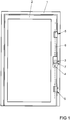
- the espagnolette lock 3 has a main lock 4 and a plurality of secondary locks formed as automatic locks 5.
- the main lock 4 is connected via a drive rod 6 with the automatic locks 5 and has a
- the drive device 7 may be a generally known handle, a lock cylinder and / or a motor drive.
- FIG. 2 shows one of the automatic locks 5 off FIG. 1 with a arranged in the wing 2 and shown open lock case 8.
- the lock case 8 opposite is in the frame 1, a strike plate 9 made of a magnetizable material, such as steel, arranged.
- the automatic lock 5 has a retracted into the lock case 8 pivotable latch 10 and a protruding from the lock case 8 and tightened on the strike plate 9 by a magnetic force button 12.
- a spring element 11 biases the button 12 against the magnetic force in a retracted position in the lock case 8 in front.
- a spring element for biasing the bolt 10 out of the lock case 8 is not shown to simplify the drawing.
- the button 12 controls a shutter 13 arranged in the lock case 8. On the trigger 13, a support arm 14 of the bolt 10 is supported.
- FIG. 3 shows greatly enlarged the button 12 of the automatic lock 5 off FIG. 2 ,
- the button 12 has a guide member 15 made of a non-magnetic material, such as plastic.
- a magnet 16 is guided perpendicular to the strike plate 9 slidably.
- the magnet 16 has a skirt 17 made of plastic.
- the plastic of the enclosure 17 is in the direction of the strike plate 9 with an edge 18 slightly above the magnet 16, so that a direct contact of the magnet 16 with the Striker plate 9 is avoided.
- the movement of the magnet 16 is transmitted to the trigger 13 via a movable intermediate member 19.
- the magnet 16 protruding, in guides 20 of the intermediate member 19 penetrating actuators 21.
- the intermediate member 19 also has adjusting elements 22, with which it penetrates into an elongated guide 23 of the trigger 13.
- the spring element 11 acts on the magnet 16.
- the range of movement of the magnet 16 in the guide member 15 is limited by a stop 25.
- FIG. 4 shows a sectional view through the button 12 FIG. 3 along the line IV - IV. It can be seen that the guides 20 of the adjusting elements 21 of the magnet 16 in the intermediate member 19 are inclined. Therefore, upon movement of the magnet 16 perpendicular to the in FIG. 3 shown striking plate 9, the intermediate member 19 laterally displaced.
- FIG. 5 shows a view of the button 12 from position 5 FIG. 3 , It can be seen that the adjusting elements 22 of the intermediate member 19 in the vertical to the in FIG. 3 shown guide plate 9 arranged guide 23 of the trigger 13 penetrate. The guides 20, 23 of the intermediate member 19 in the trigger 13 and with respect to the magnet 16 are thus inclined to each other. The adjusting elements 22 of the intermediate member 19 are guided in straight guides 24 of the guide member 15.
- the guide member 15 In the ground state of the automatic lock 5, in which the wing 2 is removed from the frame, the guide member 15 is located with the magnet 16 in a retracted position in the lock case 8. In this position, the guide member 15 is held with the magnet 16 of the spring element 11. The magnet 16 is supported on the stop 25 of the guide member 15 from. While closing the door and thus during the movement of the wing 2 against the frame 1 exceeds the magnetic force between the magnet 16 and the striking plate 9, the spring force of the spring element 11. First, the magnet 16 is held in its position in the guide member 15 due to frictional forces of the trigger 13, until the guide member 15 comes against the strike plate 9.
- the magnet 16 is in a defined position relative to the striking plate 9 and can thereby actuate the intermediate member 19 and the trigger 13 with a defined magnetic force.
- the magnet 16 could be magnetically held by a small, not shown, metal plate on the stop 25 and reset there with the door open.
- the spring 11 could then alternatively be articulated only on the guide member 15.
Landscapes
- Engineering & Computer Science (AREA)
- Mechanical Engineering (AREA)
- Structural Engineering (AREA)
- Lock And Its Accessories (AREA)
Claims (8)
- Serrure automatique (5) avec un boîtier de serrure (8) et avec une gâche (9) à disposer en face, avec un verrou (10) mobile entre une position ouverte se trouvant dans le boîtier de serrure (8) et une position fermée dépassant du boîtier de serrure (8) et avec un bouton (12) mobile hors du boîtier de serrure (8) pour la détection de la position du boîtier de serrure (8) par rapport à la gâche (9) et avec un déclencheur (13) contrôlé par le bouton (12) pour la libération du mouvement du verrou (10) de la position ouverte vers la position fermée, le bouton (12) comprenant une partie de guidage (15) en matériau non magnétique mobile en direction de la gâche (9), caractérisée en ce qu'un aimant (16) est guidé de manière coulissante perpendiculairement à la gâche (9) dans la partie de guidage (15) lorsque le boîtier (8) se trouve en face de la gâche (9) et est maintenu, de manière élastique, conjointement avec la partie de guidage (15), dans une position de base, dans une position rétractée et en ce que les mouvements du déclencheur (13) sont couplés avec l'aimant (16), les forces de retenue lors du mouvement de la partie de guidage (15) étant plus faibles que les forces d'actionnement du déclencheur (13).
- Serrure automatique selon la revendication 1, caractérisée en ce que l'aimant (16) est orienté, avec une face frontale, vers la gâche (9) et en ce que la partie de guidage (15) entoure latéralement l'aimant (16).
- Serrure automatique selon la revendication 1 ou 2, caractérisée en ce que l'aimant (16) est inséré au moins partiellement dans une matière plastique et en ce que la matière plastique est en léger porte-à-faux au niveau de la face frontale de l'aimant (16).
- Serrure automatique selon l'une des revendications 1 à 3, caractérisée en ce que la partie de guidage (15) est constituée de matière plastique.
- Serrure automatique selon l'une des revendications 1 à 4, caractérisée en ce que l'aimant (16) comprend un élément de réglage (21) et en ce que le mouvement de l'élément de réglage (21) est couplé avec le déclencheur (13).
- Serrure automatique selon l'une des revendications 1 à 5, caractérisée en ce que, entre l'aimant (16) et le déclencheur (13), est disposé un organe intermédiaire (19) pour la transmission du mouvement de l'aimant (16) au déclencheur (13), l'aimant (16), le déclencheur (13) et l'organe intermédiaire (19) étant conçus comme des composants séparés.
- Serrure automatique selon la revendication 6, caractérisée en ce que chaque organe intermédiaire (19) comprend un guidage (20, 24) par rapport à l'aimant (16) et à la partie de guidage (15) et en ce que les guidages (20, 24) sont inclinés les uns vers les autres.
- Serrure automatique selon l'une des revendications 1 à 7, caractérisée en ce qu'un élément à ressort (11) précontraint l'aimant (16) dans une position rétractée dans le boîtier de serrure (5) et en ce que l'aimant (16) s'appuie, dans la position rétractée, contre une butée (25) de la partie de guidage (15).
Applications Claiming Priority (1)
| Application Number | Priority Date | Filing Date | Title |
|---|---|---|---|
| DE201210213989 DE102012213989A1 (de) | 2012-08-07 | 2012-08-07 | Automatikschloss |
Publications (3)
| Publication Number | Publication Date |
|---|---|
| EP2696014A2 EP2696014A2 (fr) | 2014-02-12 |
| EP2696014A3 EP2696014A3 (fr) | 2017-11-22 |
| EP2696014B1 true EP2696014B1 (fr) | 2019-02-20 |
Family
ID=48917420
Family Applications (1)
| Application Number | Title | Priority Date | Filing Date |
|---|---|---|---|
| EP13179233.5A Active EP2696014B1 (fr) | 2012-08-07 | 2013-08-05 | Serrure automatique |
Country Status (2)
| Country | Link |
|---|---|
| EP (1) | EP2696014B1 (fr) |
| DE (1) | DE102012213989A1 (fr) |
Family Cites Families (4)
| Publication number | Priority date | Publication date | Assignee | Title |
|---|---|---|---|---|
| DE8704036U1 (de) * | 1987-03-18 | 1987-07-02 | BKS GmbH, 5620 Velbert | Türschloß mit Verriegelungselement und Hilfsfalle |
| FI20041698A (fi) * | 2004-12-31 | 2006-07-01 | Roca Finland Oy | Lukko |
| CN201232416Y (zh) * | 2008-07-01 | 2009-05-06 | 李建华 | 具有磁控锁舌弹出机构的自动门锁 |
| DE202009014455U1 (de) | 2009-10-26 | 2010-02-11 | Kfv Karl Fliether Gmbh & Co. Kg | Treibstangensperre |
-
2012
- 2012-08-07 DE DE201210213989 patent/DE102012213989A1/de not_active Withdrawn
-
2013
- 2013-08-05 EP EP13179233.5A patent/EP2696014B1/fr active Active
Also Published As
| Publication number | Publication date |
|---|---|
| EP2696014A3 (fr) | 2017-11-22 |
| DE102012213989A1 (de) | 2014-02-13 |
| EP2696014A2 (fr) | 2014-02-12 |
Similar Documents
| Publication | Publication Date | Title |
|---|---|---|
| EP2096241B1 (fr) | Verrou supplémentaire à verrouillage automatique | |
| EP1970505B1 (fr) | Serrure anti-panique | |
| EP2673435A1 (fr) | Système de serrure pour bloc-porte à deux vantaux à fonction anti-panique | |
| DE3801441C2 (fr) | ||
| EP2673434B1 (fr) | Serrure dotée d'un loquet et d'un loquet supplémentaire destiné à empêcher le déplacement d'un pêne | |
| EP3336287B1 (fr) | Dispositif de verrouillage pour une porte à deux battants | |
| EP2634333B1 (fr) | Serrure | |
| EP3208407B1 (fr) | Verrou dote d'un dispositif de securite | |
| EP3091151A1 (fr) | Verrouillage de tringle pour une serrure de tringle | |
| EP2696014B1 (fr) | Serrure automatique | |
| EP2634330B1 (fr) | Serrure automatique | |
| DE8704036U1 (de) | Türschloß mit Verriegelungselement und Hilfsfalle | |
| EP2696013B1 (fr) | Serrure automatique | |
| EP3249141B1 (fr) | Serrure comprenant un pêne et un pêne supplémentaire pour la sécurité d'écoulement | |
| EP2738324B1 (fr) | Serrure dotée d'une unité de rotation débloquable | |
| EP2634331B1 (fr) | Serrure automatique | |
| EP1555365B1 (fr) | Crémone-serrure | |
| EP3112564A1 (fr) | Serrure à loquet à verrouillage automatique | |
| EP3336289B1 (fr) | Dispositif de verrouillage pour une porte à deux battants | |
| EP1514987A2 (fr) | Crémone | |
| DE102016118101A1 (de) | Verriegelungsvorrichtung mit Ausgleichsschieber und Übertragungselement | |
| EP3029233A1 (fr) | Crémone-serrure | |
| EP1514986A2 (fr) | Crémone | |
| DE202015000106U1 (de) | Schloss | |
| DE202012005382U1 (de) | Vorrichtung zur gesicherten Fallenfeststellung |
Legal Events
| Date | Code | Title | Description |
|---|---|---|---|
| AK | Designated contracting states |
Kind code of ref document: A2 Designated state(s): AL AT BE BG CH CY CZ DE DK EE ES FI FR GB GR HR HU IE IS IT LI LT LU LV MC MK MT NL NO PL PT RO RS SE SI SK SM TR |
|
| AX | Request for extension of the european patent |
Extension state: BA ME |
|
| PUAI | Public reference made under article 153(3) epc to a published international application that has entered the european phase |
Free format text: ORIGINAL CODE: 0009012 |
|
| PUAL | Search report despatched |
Free format text: ORIGINAL CODE: 0009013 |
|
| AK | Designated contracting states |
Kind code of ref document: A3 Designated state(s): AL AT BE BG CH CY CZ DE DK EE ES FI FR GB GR HR HU IE IS IT LI LT LU LV MC MK MT NL NO PL PT RO RS SE SI SK SM TR |
|
| AX | Request for extension of the european patent |
Extension state: BA ME |
|
| RIC1 | Information provided on ipc code assigned before grant |
Ipc: E05B 47/00 20060101ALI20171017BHEP Ipc: E05C 9/18 20060101ALI20171017BHEP Ipc: E05B 63/20 20060101AFI20171017BHEP |
|
| STAA | Information on the status of an ep patent application or granted ep patent |
Free format text: STATUS: REQUEST FOR EXAMINATION WAS MADE |
|
| 17P | Request for examination filed |
Effective date: 20180418 |
|
| RBV | Designated contracting states (corrected) |
Designated state(s): AL AT BE BG CH CY CZ DE DK EE ES FI FR GB GR HR HU IE IS IT LI LT LU LV MC MK MT NL NO PL PT RO RS SE SI SK SM TR |
|
| REG | Reference to a national code |
Ref country code: DE Ref legal event code: R079 Ref document number: 502013012206 Country of ref document: DE Free format text: PREVIOUS MAIN CLASS: E05B0063200000 Ipc: E05B0015040000 |
|
| GRAP | Despatch of communication of intention to grant a patent |
Free format text: ORIGINAL CODE: EPIDOSNIGR1 |
|
| RIC1 | Information provided on ipc code assigned before grant |
Ipc: E05B 15/04 20060101AFI20180830BHEP |
|
| STAA | Information on the status of an ep patent application or granted ep patent |
Free format text: STATUS: GRANT OF PATENT IS INTENDED |
|
| INTG | Intention to grant announced |
Effective date: 20181004 |
|
| GRAS | Grant fee paid |
Free format text: ORIGINAL CODE: EPIDOSNIGR3 |
|
| GRAA | (expected) grant |
Free format text: ORIGINAL CODE: 0009210 |
|
| STAA | Information on the status of an ep patent application or granted ep patent |
Free format text: STATUS: THE PATENT HAS BEEN GRANTED |
|
| AK | Designated contracting states |
Kind code of ref document: B1 Designated state(s): AL AT BE BG CH CY CZ DE DK EE ES FI FR GB GR HR HU IE IS IT LI LT LU LV MC MK MT NL NO PL PT RO RS SE SI SK SM TR |
|
| REG | Reference to a national code |
Ref country code: GB Ref legal event code: FG4D Free format text: NOT ENGLISH |
|
| REG | Reference to a national code |
Ref country code: CH Ref legal event code: EP |
|
| REG | Reference to a national code |
Ref country code: DE Ref legal event code: R096 Ref document number: 502013012206 Country of ref document: DE |
|
| REG | Reference to a national code |
Ref country code: AT Ref legal event code: REF Ref document number: 1098374 Country of ref document: AT Kind code of ref document: T Effective date: 20190315 |
|
| REG | Reference to a national code |
Ref country code: IE Ref legal event code: FG4D Free format text: LANGUAGE OF EP DOCUMENT: GERMAN |
|
| REG | Reference to a national code |
Ref country code: NL Ref legal event code: FP |
|
| REG | Reference to a national code |
Ref country code: LT Ref legal event code: MG4D |
|
| PG25 | Lapsed in a contracting state [announced via postgrant information from national office to epo] |
Ref country code: LT Free format text: LAPSE BECAUSE OF FAILURE TO SUBMIT A TRANSLATION OF THE DESCRIPTION OR TO PAY THE FEE WITHIN THE PRESCRIBED TIME-LIMIT Effective date: 20190220 Ref country code: PT Free format text: LAPSE BECAUSE OF FAILURE TO SUBMIT A TRANSLATION OF THE DESCRIPTION OR TO PAY THE FEE WITHIN THE PRESCRIBED TIME-LIMIT Effective date: 20190620 Ref country code: FI Free format text: LAPSE BECAUSE OF FAILURE TO SUBMIT A TRANSLATION OF THE DESCRIPTION OR TO PAY THE FEE WITHIN THE PRESCRIBED TIME-LIMIT Effective date: 20190220 Ref country code: SE Free format text: LAPSE BECAUSE OF FAILURE TO SUBMIT A TRANSLATION OF THE DESCRIPTION OR TO PAY THE FEE WITHIN THE PRESCRIBED TIME-LIMIT Effective date: 20190220 Ref country code: NO Free format text: LAPSE BECAUSE OF FAILURE TO SUBMIT A TRANSLATION OF THE DESCRIPTION OR TO PAY THE FEE WITHIN THE PRESCRIBED TIME-LIMIT Effective date: 20190520 |
|
| PG25 | Lapsed in a contracting state [announced via postgrant information from national office to epo] |
Ref country code: HR Free format text: LAPSE BECAUSE OF FAILURE TO SUBMIT A TRANSLATION OF THE DESCRIPTION OR TO PAY THE FEE WITHIN THE PRESCRIBED TIME-LIMIT Effective date: 20190220 Ref country code: RS Free format text: LAPSE BECAUSE OF FAILURE TO SUBMIT A TRANSLATION OF THE DESCRIPTION OR TO PAY THE FEE WITHIN THE PRESCRIBED TIME-LIMIT Effective date: 20190220 Ref country code: BG Free format text: LAPSE BECAUSE OF FAILURE TO SUBMIT A TRANSLATION OF THE DESCRIPTION OR TO PAY THE FEE WITHIN THE PRESCRIBED TIME-LIMIT Effective date: 20190520 Ref country code: GR Free format text: LAPSE BECAUSE OF FAILURE TO SUBMIT A TRANSLATION OF THE DESCRIPTION OR TO PAY THE FEE WITHIN THE PRESCRIBED TIME-LIMIT Effective date: 20190521 Ref country code: LV Free format text: LAPSE BECAUSE OF FAILURE TO SUBMIT A TRANSLATION OF THE DESCRIPTION OR TO PAY THE FEE WITHIN THE PRESCRIBED TIME-LIMIT Effective date: 20190220 Ref country code: IS Free format text: LAPSE BECAUSE OF FAILURE TO SUBMIT A TRANSLATION OF THE DESCRIPTION OR TO PAY THE FEE WITHIN THE PRESCRIBED TIME-LIMIT Effective date: 20190620 |
|
| PG25 | Lapsed in a contracting state [announced via postgrant information from national office to epo] |
Ref country code: AL Free format text: LAPSE BECAUSE OF FAILURE TO SUBMIT A TRANSLATION OF THE DESCRIPTION OR TO PAY THE FEE WITHIN THE PRESCRIBED TIME-LIMIT Effective date: 20190220 Ref country code: IT Free format text: LAPSE BECAUSE OF FAILURE TO SUBMIT A TRANSLATION OF THE DESCRIPTION OR TO PAY THE FEE WITHIN THE PRESCRIBED TIME-LIMIT Effective date: 20190220 Ref country code: DK Free format text: LAPSE BECAUSE OF FAILURE TO SUBMIT A TRANSLATION OF THE DESCRIPTION OR TO PAY THE FEE WITHIN THE PRESCRIBED TIME-LIMIT Effective date: 20190220 Ref country code: EE Free format text: LAPSE BECAUSE OF FAILURE TO SUBMIT A TRANSLATION OF THE DESCRIPTION OR TO PAY THE FEE WITHIN THE PRESCRIBED TIME-LIMIT Effective date: 20190220 Ref country code: SK Free format text: LAPSE BECAUSE OF FAILURE TO SUBMIT A TRANSLATION OF THE DESCRIPTION OR TO PAY THE FEE WITHIN THE PRESCRIBED TIME-LIMIT Effective date: 20190220 Ref country code: RO Free format text: LAPSE BECAUSE OF FAILURE TO SUBMIT A TRANSLATION OF THE DESCRIPTION OR TO PAY THE FEE WITHIN THE PRESCRIBED TIME-LIMIT Effective date: 20190220 Ref country code: CZ Free format text: LAPSE BECAUSE OF FAILURE TO SUBMIT A TRANSLATION OF THE DESCRIPTION OR TO PAY THE FEE WITHIN THE PRESCRIBED TIME-LIMIT Effective date: 20190220 Ref country code: ES Free format text: LAPSE BECAUSE OF FAILURE TO SUBMIT A TRANSLATION OF THE DESCRIPTION OR TO PAY THE FEE WITHIN THE PRESCRIBED TIME-LIMIT Effective date: 20190220 |
|
| REG | Reference to a national code |
Ref country code: DE Ref legal event code: R097 Ref document number: 502013012206 Country of ref document: DE |
|
| PG25 | Lapsed in a contracting state [announced via postgrant information from national office to epo] |
Ref country code: SM Free format text: LAPSE BECAUSE OF FAILURE TO SUBMIT A TRANSLATION OF THE DESCRIPTION OR TO PAY THE FEE WITHIN THE PRESCRIBED TIME-LIMIT Effective date: 20190220 Ref country code: PL Free format text: LAPSE BECAUSE OF FAILURE TO SUBMIT A TRANSLATION OF THE DESCRIPTION OR TO PAY THE FEE WITHIN THE PRESCRIBED TIME-LIMIT Effective date: 20190220 |
|
| PLBE | No opposition filed within time limit |
Free format text: ORIGINAL CODE: 0009261 |
|
| STAA | Information on the status of an ep patent application or granted ep patent |
Free format text: STATUS: NO OPPOSITION FILED WITHIN TIME LIMIT |
|
| 26N | No opposition filed |
Effective date: 20191121 |
|
| PG25 | Lapsed in a contracting state [announced via postgrant information from national office to epo] |
Ref country code: SI Free format text: LAPSE BECAUSE OF FAILURE TO SUBMIT A TRANSLATION OF THE DESCRIPTION OR TO PAY THE FEE WITHIN THE PRESCRIBED TIME-LIMIT Effective date: 20190220 |
|
| PG25 | Lapsed in a contracting state [announced via postgrant information from national office to epo] |
Ref country code: TR Free format text: LAPSE BECAUSE OF FAILURE TO SUBMIT A TRANSLATION OF THE DESCRIPTION OR TO PAY THE FEE WITHIN THE PRESCRIBED TIME-LIMIT Effective date: 20190220 |
|
| PG25 | Lapsed in a contracting state [announced via postgrant information from national office to epo] |
Ref country code: MC Free format text: LAPSE BECAUSE OF FAILURE TO SUBMIT A TRANSLATION OF THE DESCRIPTION OR TO PAY THE FEE WITHIN THE PRESCRIBED TIME-LIMIT Effective date: 20190220 Ref country code: LI Free format text: LAPSE BECAUSE OF NON-PAYMENT OF DUE FEES Effective date: 20190831 Ref country code: CH Free format text: LAPSE BECAUSE OF NON-PAYMENT OF DUE FEES Effective date: 20190831 Ref country code: LU Free format text: LAPSE BECAUSE OF NON-PAYMENT OF DUE FEES Effective date: 20190805 |
|
| REG | Reference to a national code |
Ref country code: BE Ref legal event code: MM Effective date: 20190831 |
|
| PG25 | Lapsed in a contracting state [announced via postgrant information from national office to epo] |
Ref country code: IE Free format text: LAPSE BECAUSE OF NON-PAYMENT OF DUE FEES Effective date: 20190805 |
|
| PG25 | Lapsed in a contracting state [announced via postgrant information from national office to epo] |
Ref country code: BE Free format text: LAPSE BECAUSE OF NON-PAYMENT OF DUE FEES Effective date: 20190831 |
|
| PGFP | Annual fee paid to national office [announced via postgrant information from national office to epo] |
Ref country code: NL Payment date: 20200827 Year of fee payment: 8 |
|
| PG25 | Lapsed in a contracting state [announced via postgrant information from national office to epo] |
Ref country code: CY Free format text: LAPSE BECAUSE OF FAILURE TO SUBMIT A TRANSLATION OF THE DESCRIPTION OR TO PAY THE FEE WITHIN THE PRESCRIBED TIME-LIMIT Effective date: 20190220 |
|
| PG25 | Lapsed in a contracting state [announced via postgrant information from national office to epo] |
Ref country code: MT Free format text: LAPSE BECAUSE OF FAILURE TO SUBMIT A TRANSLATION OF THE DESCRIPTION OR TO PAY THE FEE WITHIN THE PRESCRIBED TIME-LIMIT Effective date: 20190220 Ref country code: HU Free format text: LAPSE BECAUSE OF FAILURE TO SUBMIT A TRANSLATION OF THE DESCRIPTION OR TO PAY THE FEE WITHIN THE PRESCRIBED TIME-LIMIT; INVALID AB INITIO Effective date: 20130805 |
|
| PGFP | Annual fee paid to national office [announced via postgrant information from national office to epo] |
Ref country code: AT Payment date: 20210819 Year of fee payment: 9 |
|
| REG | Reference to a national code |
Ref country code: NL Ref legal event code: MM Effective date: 20210901 |
|
| PG25 | Lapsed in a contracting state [announced via postgrant information from national office to epo] |
Ref country code: NL Free format text: LAPSE BECAUSE OF NON-PAYMENT OF DUE FEES Effective date: 20210901 Ref country code: MK Free format text: LAPSE BECAUSE OF FAILURE TO SUBMIT A TRANSLATION OF THE DESCRIPTION OR TO PAY THE FEE WITHIN THE PRESCRIBED TIME-LIMIT Effective date: 20190220 |
|
| PGFP | Annual fee paid to national office [announced via postgrant information from national office to epo] |
Ref country code: GB Payment date: 20220824 Year of fee payment: 10 |
|
| REG | Reference to a national code |
Ref country code: AT Ref legal event code: MM01 Ref document number: 1098374 Country of ref document: AT Kind code of ref document: T Effective date: 20220805 |
|
| PG25 | Lapsed in a contracting state [announced via postgrant information from national office to epo] |
Ref country code: AT Free format text: LAPSE BECAUSE OF NON-PAYMENT OF DUE FEES Effective date: 20220805 |
|
| P01 | Opt-out of the competence of the unified patent court (upc) registered |
Effective date: 20230512 |
|
| PGFP | Annual fee paid to national office [announced via postgrant information from national office to epo] |
Ref country code: FR Payment date: 20230821 Year of fee payment: 11 Ref country code: DE Payment date: 20230822 Year of fee payment: 11 |
|
| GBPC | Gb: european patent ceased through non-payment of renewal fee |
Effective date: 20230805 |
|
| PG25 | Lapsed in a contracting state [announced via postgrant information from national office to epo] |
Ref country code: GB Free format text: LAPSE BECAUSE OF NON-PAYMENT OF DUE FEES Effective date: 20230805 |
|
| PG25 | Lapsed in a contracting state [announced via postgrant information from national office to epo] |
Ref country code: GB Free format text: LAPSE BECAUSE OF NON-PAYMENT OF DUE FEES Effective date: 20230805 |