EP2695704A1 - Verfahren zur Herstellung eines TIAL-Leitschaufelkranzes für eine Gasturbine sowie ein entsprechender Leitschaufelkranz - Google Patents
Verfahren zur Herstellung eines TIAL-Leitschaufelkranzes für eine Gasturbine sowie ein entsprechender Leitschaufelkranz Download PDFInfo
- Publication number
- EP2695704A1 EP2695704A1 EP12179785.6A EP12179785A EP2695704A1 EP 2695704 A1 EP2695704 A1 EP 2695704A1 EP 12179785 A EP12179785 A EP 12179785A EP 2695704 A1 EP2695704 A1 EP 2695704A1
- Authority
- EP
- European Patent Office
- Prior art keywords
- blanks
- ring segment
- blade ring
- friction welding
- welding
- Prior art date
- Legal status (The legal status is an assumption and is not a legal conclusion. Google has not performed a legal analysis and makes no representation as to the accuracy of the status listed.)
- Granted
Links
- 238000000034 method Methods 0.000 title claims abstract description 44
- 238000004519 manufacturing process Methods 0.000 title claims description 12
- 238000003466 welding Methods 0.000 claims abstract description 37
- 239000000463 material Substances 0.000 claims abstract description 33
- 238000005304 joining Methods 0.000 claims abstract description 23
- 238000010438 heat treatment Methods 0.000 claims abstract description 11
- 238000012805 post-processing Methods 0.000 claims abstract description 10
- 238000010894 electron beam technology Methods 0.000 claims abstract description 7
- 238000005476 soldering Methods 0.000 claims abstract description 7
- 239000002131 composite material Substances 0.000 claims abstract description 4
- 230000007704 transition Effects 0.000 claims abstract description 4
- 230000001939 inductive effect Effects 0.000 claims abstract description 3
- 229910010038 TiAl Inorganic materials 0.000 claims description 20
- 238000005242 forging Methods 0.000 claims description 12
- 229910052759 nickel Inorganic materials 0.000 claims description 10
- 229910000679 solder Inorganic materials 0.000 claims description 9
- 229910052719 titanium Inorganic materials 0.000 claims description 6
- UQZIWOQVLUASCR-UHFFFAOYSA-N alumane;titanium Chemical compound [AlH3].[Ti] UQZIWOQVLUASCR-UHFFFAOYSA-N 0.000 abstract 6
- 238000005219 brazing Methods 0.000 abstract 2
- HZEWFHLRYVTOIW-UHFFFAOYSA-N [Ti].[Ni] Chemical compound [Ti].[Ni] HZEWFHLRYVTOIW-UHFFFAOYSA-N 0.000 abstract 1
- PXHVJJICTQNCMI-UHFFFAOYSA-N Nickel Chemical compound [Ni] PXHVJJICTQNCMI-UHFFFAOYSA-N 0.000 description 19
- XEEYBQQBJWHFJM-UHFFFAOYSA-N Iron Chemical compound [Fe] XEEYBQQBJWHFJM-UHFFFAOYSA-N 0.000 description 6
- 229910052710 silicon Inorganic materials 0.000 description 6
- 239000010703 silicon Substances 0.000 description 6
- ZOXJGFHDIHLPTG-UHFFFAOYSA-N Boron Chemical compound [B] ZOXJGFHDIHLPTG-UHFFFAOYSA-N 0.000 description 5
- RTAQQCXQSZGOHL-UHFFFAOYSA-N Titanium Chemical compound [Ti] RTAQQCXQSZGOHL-UHFFFAOYSA-N 0.000 description 5
- 229910052796 boron Inorganic materials 0.000 description 5
- 239000010936 titanium Substances 0.000 description 5
- VYZAMTAEIAYCRO-UHFFFAOYSA-N Chromium Chemical compound [Cr] VYZAMTAEIAYCRO-UHFFFAOYSA-N 0.000 description 4
- 229910052804 chromium Inorganic materials 0.000 description 4
- 239000011651 chromium Substances 0.000 description 4
- 229910052742 iron Inorganic materials 0.000 description 3
- 238000007493 shaping process Methods 0.000 description 3
- 239000000470 constituent Substances 0.000 description 2
- 238000005457 optimization Methods 0.000 description 2
- OKTJSMMVPCPJKN-UHFFFAOYSA-N Carbon Chemical compound [C] OKTJSMMVPCPJKN-UHFFFAOYSA-N 0.000 description 1
- ZOKXTWBITQBERF-UHFFFAOYSA-N Molybdenum Chemical compound [Mo] ZOKXTWBITQBERF-UHFFFAOYSA-N 0.000 description 1
- 238000002679 ablation Methods 0.000 description 1
- 238000005275 alloying Methods 0.000 description 1
- 229910021325 alpha 2-Ti3Al Inorganic materials 0.000 description 1
- XAGFODPZIPBFFR-UHFFFAOYSA-N aluminium Chemical compound [Al] XAGFODPZIPBFFR-UHFFFAOYSA-N 0.000 description 1
- 229910052782 aluminium Inorganic materials 0.000 description 1
- 230000015572 biosynthetic process Effects 0.000 description 1
- 229910052799 carbon Inorganic materials 0.000 description 1
- 230000006835 compression Effects 0.000 description 1
- 238000007906 compression Methods 0.000 description 1
- 238000005336 cracking Methods 0.000 description 1
- 230000006735 deficit Effects 0.000 description 1
- 230000001419 dependent effect Effects 0.000 description 1
- 238000013461 design Methods 0.000 description 1
- 238000006073 displacement reaction Methods 0.000 description 1
- 230000000694 effects Effects 0.000 description 1
- 230000002349 favourable effect Effects 0.000 description 1
- 239000012530 fluid Substances 0.000 description 1
- 239000007788 liquid Substances 0.000 description 1
- 238000003801 milling Methods 0.000 description 1
- 238000012986 modification Methods 0.000 description 1
- 230000004048 modification Effects 0.000 description 1
- 229910052750 molybdenum Inorganic materials 0.000 description 1
- 239000011733 molybdenum Substances 0.000 description 1
- 229910052758 niobium Inorganic materials 0.000 description 1
- 239000010955 niobium Substances 0.000 description 1
- GUCVJGMIXFAOAE-UHFFFAOYSA-N niobium atom Chemical compound [Nb] GUCVJGMIXFAOAE-UHFFFAOYSA-N 0.000 description 1
- 239000011148 porous material Substances 0.000 description 1
- 238000012546 transfer Methods 0.000 description 1
- 229910006281 γ-TiAl Inorganic materials 0.000 description 1
Images
Classifications
-
- F—MECHANICAL ENGINEERING; LIGHTING; HEATING; WEAPONS; BLASTING
- F01—MACHINES OR ENGINES IN GENERAL; ENGINE PLANTS IN GENERAL; STEAM ENGINES
- F01D—NON-POSITIVE DISPLACEMENT MACHINES OR ENGINES, e.g. STEAM TURBINES
- F01D5/00—Blades; Blade-carrying members; Heating, heat-insulating, cooling or antivibration means on the blades or the members
- F01D5/12—Blades
- F01D5/28—Selecting particular materials; Particular measures relating thereto; Measures against erosion or corrosion
-
- B—PERFORMING OPERATIONS; TRANSPORTING
- B23—MACHINE TOOLS; METAL-WORKING NOT OTHERWISE PROVIDED FOR
- B23P—METAL-WORKING NOT OTHERWISE PROVIDED FOR; COMBINED OPERATIONS; UNIVERSAL MACHINE TOOLS
- B23P15/00—Making specific metal objects by operations not covered by a single other subclass or a group in this subclass
- B23P15/006—Making specific metal objects by operations not covered by a single other subclass or a group in this subclass turbine wheels
-
- C—CHEMISTRY; METALLURGY
- C22—METALLURGY; FERROUS OR NON-FERROUS ALLOYS; TREATMENT OF ALLOYS OR NON-FERROUS METALS
- C22F—CHANGING THE PHYSICAL STRUCTURE OF NON-FERROUS METALS AND NON-FERROUS ALLOYS
- C22F1/00—Changing the physical structure of non-ferrous metals or alloys by heat treatment or by hot or cold working
- C22F1/16—Changing the physical structure of non-ferrous metals or alloys by heat treatment or by hot or cold working of other metals or alloys based thereon
- C22F1/18—High-melting or refractory metals or alloys based thereon
- C22F1/183—High-melting or refractory metals or alloys based thereon of titanium or alloys based thereon
-
- F—MECHANICAL ENGINEERING; LIGHTING; HEATING; WEAPONS; BLASTING
- F01—MACHINES OR ENGINES IN GENERAL; ENGINE PLANTS IN GENERAL; STEAM ENGINES
- F01D—NON-POSITIVE DISPLACEMENT MACHINES OR ENGINES, e.g. STEAM TURBINES
- F01D5/00—Blades; Blade-carrying members; Heating, heat-insulating, cooling or antivibration means on the blades or the members
- F01D5/02—Blade-carrying members, e.g. rotors
- F01D5/04—Blade-carrying members, e.g. rotors for radial-flow machines or engines
- F01D5/043—Blade-carrying members, e.g. rotors for radial-flow machines or engines of the axial inlet- radial outlet, or vice versa, type
- F01D5/048—Form or construction
-
- F—MECHANICAL ENGINEERING; LIGHTING; HEATING; WEAPONS; BLASTING
- F01—MACHINES OR ENGINES IN GENERAL; ENGINE PLANTS IN GENERAL; STEAM ENGINES
- F01D—NON-POSITIVE DISPLACEMENT MACHINES OR ENGINES, e.g. STEAM TURBINES
- F01D5/00—Blades; Blade-carrying members; Heating, heat-insulating, cooling or antivibration means on the blades or the members
- F01D5/12—Blades
- F01D5/14—Form or construction
- F01D5/141—Shape, i.e. outer, aerodynamic form
- F01D5/146—Shape, i.e. outer, aerodynamic form of blades with tandem configuration, split blades or slotted blades
-
- F—MECHANICAL ENGINEERING; LIGHTING; HEATING; WEAPONS; BLASTING
- F01—MACHINES OR ENGINES IN GENERAL; ENGINE PLANTS IN GENERAL; STEAM ENGINES
- F01D—NON-POSITIVE DISPLACEMENT MACHINES OR ENGINES, e.g. STEAM TURBINES
- F01D5/00—Blades; Blade-carrying members; Heating, heat-insulating, cooling or antivibration means on the blades or the members
- F01D5/12—Blades
- F01D5/22—Blade-to-blade connections, e.g. for damping vibrations
-
- F—MECHANICAL ENGINEERING; LIGHTING; HEATING; WEAPONS; BLASTING
- F01—MACHINES OR ENGINES IN GENERAL; ENGINE PLANTS IN GENERAL; STEAM ENGINES
- F01D—NON-POSITIVE DISPLACEMENT MACHINES OR ENGINES, e.g. STEAM TURBINES
- F01D5/00—Blades; Blade-carrying members; Heating, heat-insulating, cooling or antivibration means on the blades or the members
- F01D5/30—Fixing blades to rotors; Blade roots ; Blade spacers
-
- Y—GENERAL TAGGING OF NEW TECHNOLOGICAL DEVELOPMENTS; GENERAL TAGGING OF CROSS-SECTIONAL TECHNOLOGIES SPANNING OVER SEVERAL SECTIONS OF THE IPC; TECHNICAL SUBJECTS COVERED BY FORMER USPC CROSS-REFERENCE ART COLLECTIONS [XRACs] AND DIGESTS
- Y02—TECHNOLOGIES OR APPLICATIONS FOR MITIGATION OR ADAPTATION AGAINST CLIMATE CHANGE
- Y02T—CLIMATE CHANGE MITIGATION TECHNOLOGIES RELATED TO TRANSPORTATION
- Y02T50/00—Aeronautics or air transport
- Y02T50/60—Efficient propulsion technologies, e.g. for aircraft
-
- Y—GENERAL TAGGING OF NEW TECHNOLOGICAL DEVELOPMENTS; GENERAL TAGGING OF CROSS-SECTIONAL TECHNOLOGIES SPANNING OVER SEVERAL SECTIONS OF THE IPC; TECHNICAL SUBJECTS COVERED BY FORMER USPC CROSS-REFERENCE ART COLLECTIONS [XRACs] AND DIGESTS
- Y10—TECHNICAL SUBJECTS COVERED BY FORMER USPC
- Y10T—TECHNICAL SUBJECTS COVERED BY FORMER US CLASSIFICATION
- Y10T29/00—Metal working
- Y10T29/49—Method of mechanical manufacture
- Y10T29/49316—Impeller making
- Y10T29/49336—Blade making
Definitions
- the present invention relates to a method for producing a blade ring for a gas turbine, in particular for an aircraft engine and a corresponding blade ring segment.
- a method of manufacturing a vane ring is known in which vane blanks are made by forging, for example, to be welded together into a vane segment.
- a cost-effective method for producing a vane ring is to be created and it should displacements of adjacent blades against each other are avoided to achieve a fluid dynamics optimization.
- blade ring segments for example so-called blade twins, that is to say blade ring segments with two blade leaves, which have a common blade root.
- blade twins that is to say blade ring segments with two blade leaves, which have a common blade root.
- a corresponding method should thus be easy to carry out overall and provide reliable and reproducible results in the form of heavy-duty blade ring segments, in particular blade ring segments, with a low weight.
- a blade ring segment for a gas turbine in particular for an aircraft engine, and in particular a blade ring segment can be made of a TiAl material, wherein at least two adjacent blades have a single common blade root. Accordingly, according to another aspect of the present invention, protection for a corresponding blade ring segment is claimed independently and in combination with other aspects of the invention.
- the structure required for the mechanical properties of the TiAl material is adjusted by suitable shaping or forging, at least in a basic structure, which can then be optimized by subsequent heat treatment.
- suitable shaping or forging at least in a basic structure, which can then be optimized by subsequent heat treatment.
- by forming or forging the blanks can be given a shape that can range over a large range of non-conformed to the final shape basic shapes to close to final shape blanks.
- the post-processing of the joined blanks or the blade ring segment to form the final contour of the blade ring segment can be carried out by electrochemical ablation or by milling or by other suitable methods for material-removing shaping.
- the post-processing of the vane ring segment can be limited to fluidically relevant areas of the vane ring segment or carried out in this particularly intense or accurate. In this way, the fluidic properties of the blade ring segment can be improved.
- one or more heat treatments can be carried out between the step of joining and the post-processing by material-removing methods or after completion of the final contour in order to adjust the structure of the material so that the desired properties, such as strength properties, are achieved become.
- the joining methods used are geheschafonend, so have only a minor impact on the microstructure in the joining zone and / or a limited joining zone, single or multiple heat treatment steps both before the joining process, as well as after the joining process and before post-processing for the production of the final contour or even after completion of the final contour. It is particularly advantageous if many process steps for the blanks already joined together can be carried out so that a separate handling of the blanks is not required, which reduces the process costs.
- the joining can be done by laser beam welding, electron beam welding, high temperature soldering or friction welding, in particular orbital friction welding or multi-orbital friction welding and linear friction welding. These methods affect a microstructure state of the blanks set by a forging manufacturing process of the blanks only to a small extent, so that they are particularly suitable for the present method.
- the blanks can be preheated above the brittle-ductile transition temperature of the TiAl material to prevent cracking.
- the soldering can be carried out with only local heating of the blanks to be joined in the region of the joining surface, in particular an inductive heating of local areas can be provided.
- solders based on titanium or nickel can be used in particular for soldering.
- the solders include, for example, Ti-base solders, Ti60CuNi, Ti70CuNi, Ni-base solders, AMS47XX, AMS4775, AMS4776, AMS4777, AMS4778, AMS4779, and AMS4782.
- Ti-base solder is understood as meaning a solder which, for example Ti60CuNi or Ti70CuNi, has a predominant proportion of titanium or titanium represents the largest constituent. In the case of Ti60CuNi or Ti70CuNi, the proportion of titanium is 60 or 70% by weight.
- Ni - base solders can be used, in which nickel is the predominant component or the largest component.
- Known nickel solders are marketed with the designations AMS47XX, where XX is a wildcard for numbers between 1 and 9.
- Specific examples which are well suited to the present invention are AMS 4775 with 14 wt.% Chromium, 4.5 wt.% Iron, 4.5 wt.% Silicon, 3.1 wt.% Boron and 0.7 wt % Carbon and the balance nickel and AMS 4776 with 14% by weight chromium, 4.5% by weight iron, 4.5% by weight silicon, 3.1% by weight boron and the balance nickel, AMS 4777 with 7% by weight % Of chromium, 3% by weight of iron, 4.1% by weight of silicon, 3% by weight of boron and the balance nickel, AMS 4778 with 4.5% by weight of silicon, 2.9% by weight of boron and the remainder nickel , AMS 4779 with 3.5% by weight of silicon, 1.9% by weight of boro
- the blanks can already be joined at a very early stage of the production process or with a mold removed very far from the final contour, for example in the form of blocks.
- the blanks may preferably be formed in a simple basic shape, such as a cuboid, cylinder or the like, but additionally in the region of the intended joining zones adapted areas, such as projecting areas, so that only the necessary connection areas must be joined, while other areas, which are then removed anyway in the shaping by material removal, not need to be joined. This is particularly advantageous for the friction welding, as this can be kept low the necessary contact forces when connecting.
- TiAl materials is meant in the present invention, all materials that are made on the basis of TiAl, ie as constituents comprising the largest proportion of titanium and aluminum.
- these are materials that have intermetallic phases in the structure, such as ⁇ 2 -Ti 3 Al or ⁇ -TiAl.
- the TiAl materials can have a wide variety of alloying elements, such as niobium or molybdenum.
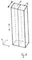
- the FIG. 1 shows in a perspective view two blanks 1 and 2 made of a TiAl material, which are formed as a cuboid.
- the blanks 1 and 2 are connected to each other fluidly along the adjacent side surfaces which extend in the z and ⁇ direction.
- the material-liquid bonding can be done for example by linear friction welding or orbital friction welding or multi-orbital friction welding.
- the surface pressures may be in the range between 20 and 200 MPa, preferably in the range between 40 and 100 MPa.
- the amplitude of movement in the linear friction welding can be in the range of 1 millimeter to 8 millimeters, preferably 2 millimeters to 4 millimeters, with a frequency of 15 1 / s to 150 1 / s, preferably 30 1 / s to 100 1 for the oscillating movement / s, can be adjusted.
- the possible relative movements of the blanks during friction welding are indicated by the double arrows.
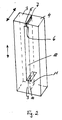
- FIG. 2 shows a second embodiment in which two compared to the embodiment of FIG. 1 differently shaped blanks 3.4 are joined together.
- the blanks 3, 4 in turn have a substantially cuboid base body, which however has lateral projections 5, 6 or 9, 10 at the ends, so that the blanks 3, 4 have a C shape.
- the blanks 3, 4 are arranged with the projections 5, 6 or 9, 10 against each other and joined to the resulting contact surfaces, so that the connecting regions can also be referred to as joining zones 7, 11.
- a gap 8 is formed between the blanks 3, 4 in a middle region, which gap already corresponds to a passage between two adjacent blade leaves in the finished blade ring segment.
- the blanks 3, 4 can preferably be connected to one another by friction welding, in particular linear friction welding, wherein the oscillating friction movement for the friction welding is again indicated by the double arrows.
- the gap 8 which is arranged between the blanks to be welded 3.4, the force required for the connection during friction welding, namely the so-called compression force, significantly reduced.
- the material removal and the corresponding effort for this purpose can be reduced because less material has to be removed through the gap 8.
- Friction welding also has the advantage that no pores and cracks occur in the joining zone, since the components to be joined are pressed together under pressure.
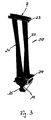
- FIG. 3 shows a correspondingly formed blade ring segment 20 with two blades 21 and 22, which are connected to each other via an outer shroud 23 and an inner shroud 24.
- the blade ring segment 20 further has a common blade root 25, which serves to arrange the blade ring segment in a disc of the gas turbine.
- a blade root for each blade or blade
- in the blade ring segment 20 according to the invention only a single blade root is provided, with which the blade ring segment is arranged in the disc.
- the joining zone runs through the middle or a central region of the foot, so that the material load is very low due to the strong formation of the foot, so that impairments of the structure by the joining have no effect.
Landscapes
- Engineering & Computer Science (AREA)
- Mechanical Engineering (AREA)
- General Engineering & Computer Science (AREA)
- Chemical & Material Sciences (AREA)
- Materials Engineering (AREA)
- Physics & Mathematics (AREA)
- Fluid Mechanics (AREA)
- Thermal Sciences (AREA)
- Crystallography & Structural Chemistry (AREA)
- Metallurgy (AREA)
- Organic Chemistry (AREA)
- Pressure Welding/Diffusion-Bonding (AREA)
Abstract
Description
- Die vorliegende Erfindung betrifft ein Verfahren zur Herstellung eines Schaufelkranzes für eine Gasturbine, insbesondere für ein Flugtriebwerk sowie einen entsprechendes Schaufelkranzsegment.
- Aus der
DE 10 2009 013 819 A1 ist ein Verfahren zur Herstellung eines Leitschaufelkranzes bekannt, bei dem Schaufelrohlinge beispielsweise schmiedetechnisch hergestellt werden, um anschließend zu einem Leitschaufelsegment zusammengeschweißt zu werden. Damit soll ein kostengünstiges Verfahren zur Herstellung eines Leitschaufelkranzes geschaffen werden und es sollen Versetzungen benachbarter Schaufeln gegeneinander vermieden werden, um eine strömungsmechanische Optimierung zu erzielen. - Die
DE 10 2009 013 819 A1 beschreibt jedoch nicht, dass mit dem vorgestellten Verfahren auch Laufschaufeln bzw. Laufschaufelkranzsegmente hergestellt werden könnten, die durch die Rotationsbewegung starken Fliehkräften ausgesetzt sind. - Gerade hier ergibt sich jedoch bei schnell drehenden Komponenten einer Gasturbine und insbesondere eines Flugtriebwerks die Notwendigkeit, eine geeignete Materialauswahl mit einem erforderlichen Design der Komponenten und einem effizienten und geeigneten Herstellungsverfahren zu kombinieren. So ist es beispielsweise für schnell drehende Niederdruckturbinenschaufeln vorteilhaft, diese aus einem TiAl-Werkstoff zu fertigen, da die TiAl-Werkstoffe ein niedriges spezifisches Gewicht und gleichzeitig die erforderlichen mechanischen Festigkeitswerte sowie eine ausreichende Beständigkeit gegenüber der in der Arbeitsumgebung herrschenden Atmosphäre aufweisen. Allerdings müssen die TiAl-Schaufeln, die hier eingesetzt werden, schmiedetechnisch hergestellt werden, um durch die geeigneten Schmiedeprozesse ein Werkstoffgefüge einzustellen, das den Festigkeitsanforderungen genügt. Gleichzeitig ist es jedoch vorteilhaft, Schaufelkranzsegmente, beispielsweise sogenannte Schaufelzwillinge, also Schaufelkranzsegmente mit zwei Schaufelblättern, einzusetzen, die einen gemeinsamen Schaufelfuß aufweisen. Dadurch ist eine strukturmechanische Optimierung möglich, die eine effiziente Anbindung der Schaufeln an eine drehende Scheibe einer Gasturbine ermöglicht und einen optimalen Lastabtrag gewährleistet.
- Allerdings sind die für die Eigenschaften einer TiAl-Schaufel erforderlichen Schmiedeprozesse für große Bauteile, wie Schaufelkranzsegmente, schwierig durchzuführen, wenn eine bestimmte Gefügeeinstellung erforderlich ist. Entsprechend ist es schwierig, eine schmiedetechnische Herstellung von TiAl - Schaufeln mit einer Kombination der Schaufeln zu Schaufelkranzsegmenten zu vereinbaren.
- Es ist deshalb Aufgabe der vorliegenden Erfindung, ein TiAl - Schaufelkranzsegment, insbesondere für Laufschaufeln einer Gasturbine und insbesondere eins Flugtriebwerks, bereitzustellen, bei dem sowohl die vorteilhaften Eigenschaften des TiAl - Werkstoffs mit niedrigem Gewicht, als auch die erforderliche Einstellung der Festigkeitswerte durch geeignete Schmiedeprozesse mit einer kostengünstigen Herstellung kombiniert werden können. Ein entsprechendes Verfahren soll somit insgesamt einfach durchführbar sein und zuverlässige und reproduzierbare Ergebnisse in Form von hochbelastbaren Schaufelkranzsegmenten, insbesondere Laufschaufelkranzsegmenten, mit einem niedrigen Gewicht bereit stellen.
- Diese Aufgabe wird gelöst durch ein Verfahren mit den Merkmalen des Anspruchs 1 sowie ein Schaufelkranzsegment mit den Merkmalen des Anspruchs 8. Vorteilhafte Ausgestaltungen sind Gegenstand der abhängigen Ansprüche.
- Gemäß der Erfindung wird das aus der
DE 10 2009 013 819 A1 für Leitschaufelkranzsegmente bekannte Verfahren auf Schaufelkranzsegmente allgemein und insbesondere Laufschaufelkranzsegmente übertragen, wobei sich überraschend herausgestellt hat, dass das Verfahren für den schwierig zu verarbeitenden Werkstoff TiAl bzw. darauf basierende Werkstoffe einsetzbar ist, ohne dass das erforderliche Gefüge, das durch Schmiedeprozesse hergestellt worden ist, in einer Weise beeinflusst wird, dass es für den Einsatz in hochbelasteten Turbinenteilen nicht mehr geeignet wäre. - Insbesondere hat sich herausgestellt, dass mit dem erfindungsgemäßen Verfahren ein Schaufelkranzsegment für eine Gasturbine, insbesondere für ein Flugtriebwerk, und insbesondere ein Laufschaufelkranzsegment aus einem TiAl-Werkstoff hergestellt werden kann, bei welchem mindestens zwei benachbarte Schaufelblätter einen einzigen gemeinsamen Schaufelfuß aufweisen. Entsprechend wird nach einem weiteren Aspekt der vorliedenden Erfindung unabhängig und in Kombination mit anderen Aspekten der Erfindung Schutz für ein entsprechendes Schaufelkranzsegment beansprucht.
- Das Verfahren umfasst die Verfahrensschritte:
- Schmieden von mindestens zwei Rohlingen aus einem TiAl-Werkstoff,
- Fügen der Rohlinge zu einem Schaufelkranz mittels eines Verfahrens zum stoffschlüssigen Verbinden und
- Nachbearbeitung des erhaltenen Rohlingverbundes durch materialabtragende Verfahren.
- Im ersten Schritt des Verfahrens wird durch geeignetes Umformen bzw. Schmieden das für die mechanischen Eigenschaften des TiAl - Werkstoffs erforderliche Gefüge eingestellt, und zwar zumindest in einer Grundstruktur, die dann durch nachfolgende Wärmebehandlung optimiert werden kann. Gleichzeitig kann durch das Umformen bzw. Schmieden den Rohlingen eine Form gegeben werden, die über einen großen Bereich von nicht an die Endform angepassten Grundformen bis zu endkonturnahen Rohlingen reichen kann.
- Die Nachbearbeitung der gefügten Rohlinge bzw. des Schaufelkranzsegments zur Ausbildung der Endkontur des Schaufelkranzsegments kann durch elektrochemisches Abtragen oder durch Fräsen oder durch sonstige geeignete Verfahren zur materialabtragenden Formgebung erfolgen. Die Nachbearbeitung des Schaufelkranzsegments kann beschränkt auf strömungsmechanisch relevante Bereiche des Schaufelkranzsegments erfolgen oder in diesen besonders intensiv oder genau durchgeführt werden. Auf diese Weise können die strömungsmechanischen Eigenschaften des Schaufelkranzsegments verbessert werden.
- Bei dem Verfahren zur Herstellung eines Schaufelkranzsegments können zwischen dem Schritt des Fügens und der Nachbearbeitung durch materialabtragende Verfahren bzw. nach Fertigstellung der Endkontur eine oder mehrere Wärmebehandlungen durchgeführt werden, um das Gefüge des Werkstoffs so einzustellen, dass die gewünschten Eigenschaften, wie beispielsweise Festigkeitseigenschaften, erreicht werden. Da die eingesetzten Fügeverfahren gefügeschonend sind, also nur einen geringen Einfluss auf die Gefügeausbildung in der Fügezone und/oder eine begrenzte Fügezone aufweisen, können einzelne oder mehrere Wärmebehandlungsschritte sowohl vor dem Fügeprozess, als auch nach dem Fügeprozess und vor der Nachbearbeitung zur Herstellung der Endkontur oder gar nach der Fertigstellung der Endkontur durchgeführt werden. Vorteilhaft ist insbesondere, wenn viele Verfahrensschritte für die bereits gefügten Rohlinge gemeinsam durchgeführt werden können, sodass eine separate Handhabung der Rohlinge nicht erforderlich ist, was die Prozesskosten senkt.
- Das Fügen kann durch Laserstrahlschweißen, Elektronenstrahlschweißen, Hochtemperaturlöten oder Reibschweißen, insbesondere Orbital-Reibschweißen oder Multiorbital-Reibschweißen sowie lineares Reibschweißen erfolgen. Diese Verfahren beeinträchtigen einen durch einen schmiedetechnischen Herstellungsprozess der Rohlinge eingestellten Gefügezustand der Rohlinge nur in einem geringen Maße, sodass sie für das vorliegende Verfahren besonders geeignet sind.
- Beim Laser- oder Elektronenstrahlschweißen können die Rohlinge über die Spröd - Duktil - Übergangstemperatur des TiAl-Werkstoffs vorgewärmt werden, um Rissbildung zu vermeiden.
- Das Löten kann bei einer nur lokalen Erwärmung der zu fügenden Rohlinge im Bereich der Fügefläche durchgeführt werden, wobei insbesondere eine induktive Erwärmung lokaler Bereiche vorgesehen werden kann.
- Für das Löten können insbesondere Lote auf Titan- oder Nickelbasis Verwendung finden. Die Lote umfassen beispielsweise Ti - Basis - Lote, Ti60CuNi, Ti70CuNi, Ni - Basis - Lote, AMS47XX, AMS4775, AMS 4776, AMS 4777, AMS 4778, AMS 4779 und AMS 4782.
- Unter Ti - Basis - Lot wird hierbei ein Lot verstanden, welches, wie beispielsweise Ti60CuNi oder Ti70CuNi, einen überwiegenden Anteil an Titan aufweist oder Titan den größten Bestandteil darstellt. Bei Ti60CuNi oder Ti70CuNi liegt der Anteil des Titan bei 60 bzw. 70 Gew.%.
- Darüber hinaus können Ni - Basis - Lote eingesetzt werden, bei denen wiederum Nickel den überwiegenden Anteil oder den größten Bestandteil darstellt. Bekannte Nickellote werden mit den Bezeichnungen AMS47XX, wobei XX als Platzhalter für Ziffern zwischen 1 und 9 steht, vertrieben. Besondere Beispiele, die gut für die vorliegende Erfindung geeignet sind, sind AMS 4775 mit 14 Gew.% Chrom, 4,5 Gew.% Eisen, 4,5 Gew.% Silizium, 3,1 Gew.% Bor und 0,7 Gew.% Kohlenstoff und dem Rest Nickel sowie AMS 4776 mit 14 Gew.% Chrom, 4,5 Gew.% Eisen, 4,5 Gew.% Silizium, 3,1 Gew.% Bor und dem Rest Nickel, AMS 4777 mit 7 Gew.% Chrom, 3 Gew.% Eisen, 4,1 Gew.% Silizium, 3 Gew.% Bor und dem Rest Nickel, AMS 4778 mit 4,5 Gew.% Silizium, 2,9 Gew.% Bor und dem Rest Nickel, AMS 4779 mit 3,5 Gew.% Silizium, 1,9 Gew.% Bor und dem Rest Nickel sowie AMS 4782 mit 19 Gew.% Chrom, 10 Gew.% Silizium und dem Rest Nickel.
- Wie bereits oben erwähnt können die Rohlinge bereits in einer sehr frühen Stufe des Herstellungsverfahrens bzw. mit einer sehr weit von der Endkontur entfernten Form gefügt werden, und zwar beispielsweise in Form von Quadern.
- Ferner können die Rohlinge vorzugsweise in einer einfach herzustellenden Grundform wie beispielsweise als Quader, Zylinder oder dergleichen ausgebildet werden, aber zusätzlich im Bereich der vorgesehenen Fügezonen angepasste Bereiche, wie z.B. hervorstehende Bereiche aufweisen, sodass lediglich die erforderlichen Verbindungsbereiche gefügt werden müssen, während andere Bereiche, die anschließend bei der Formgebung durch Materialabtrag sowieso wieder entfernt werden, nicht gefügt werden müssen. Dies ist insbesondere für das Reibschweißen vorteilhaft, da dadurch die erforderlichen Anpresskräfte beim Verbinden niedrig gehalten werden können.
- Unter TiAl-Werkstoffen sind bei der vorliegenden Erfindung alle Werkstoffe gemeint, die auf TiAl-Basis hergestellt sind, also als Bestandteile mit dem größten Anteil Titan und Aluminium umfassen. Insbesondere sind hierunter Werkstoffe zu verstehen, die intermetallische Phasen im Gefüge aufweisen, wie α2-Ti3Al oder γ-TiAl. Darüber hinaus können die TiAl-Werkstoffe verschiedenste Legierungselemente aufweisen, wie beispielsweise Niob oder Molybdän.
- Die beigefügten Zeichnungen zeigen in rein schematischer Weise in
-
Fig. 1 eine Darstellung von zwei Rohlingen zum bzw. beim Fügen; -
Fig. 2 eine Darstellung von zwei weiteren Rohlingen zum bzw. beim Fü- gen; und in -
Fig. 3 ein fertiges Schaufelkranzsegment, welches gemäß der vorliegen den Erfindung hergestellt worden ist. - Weitere Vorteile, Kennzeichen und Merkmale der vorliegenden Erfindung werden bei der nachfolgenden detaillierten Beschreibung von Ausführungsbeispielen anhand der beigefügten Zeichnungen deutlich. Die Erfindung ist jedoch nicht auf diese Ausführungsbeispiele beschränkt.
- Die
Figur 1 zeigt in einer perspektivischen Darstellung zwei Rohlinge 1 und 2 aus einem TiAl-Werkstoff, die als Quader ausgebildet sind. Die Rohlinge 1 und 2 werden entlang der benachbarten Seitenflächen, die sich in z- und γ-Richtung erstrecken, miteinander stoffflüssig verbunden. Das stoffflüssige Verbinden kann beispielsweise durch lineares Reibschweißen bzw. Orbital-Reibschweißen oder Multiorbital-Reibschweißen erfolgen. Die Flächenpressungen können beim Linear- bzw. Orbital-Reibschweißen im Bereich zwischen 20 und 200 MPa, vorzugsweise im Bereich zwischen 40 und 100 MPa liegen. Die Bewegungsamplitude beim linearen Reibschweißen kann im Bereich von 1 Millimeter bis 8 Millimeter, vorzugsweise 2 Millimeter bis 4 Millimeter, liegen, wobei für die oszillierende Bewegung eine Frequenz von 15 1/s bis 150 1/s, vorzugsweise 30 1/s bis 100 1/s, eingestellt werden kann. Die möglichen relativen Bewegungen der Rohlinge beim Reibschweißen sind durch die Doppelpfeile angezeigt. - Die
Figur 2 zeigt ein zweites Ausführungsbeispiel, bei dem zwei gegenüber dem Ausführungsbeispiel derFigur 1 unterschiedlich geformte Rohlinge 3,4 miteinander gefügt werden. Die Rohlinge 3,4 weisen wiederum einen im Wesentlichen quaderförmigen Grundkörper auf, der jedoch an den Enden jeweils seitliche Vorsprünge 5,6, bzw. 9,10 aufweist, sodass die Rohlinge 3,4 eine C-Form aufweisen. Die Rohlinge 3,4 werden mit den Vorsprüngen 5,6 bzw. 9,10 gegeneinander angeordnet und an den entstehenden Anlageflächen gefügt, sodass die Verbindungsbereiche auch als Fügezonen 7,11 bezeichnet werden können. - Zwischen den Rohlingen 3,4 ist in einem mittleren Bereich ein Spalt 8 ausgebildet, der bei dem fertig gestellten Schaufelkranzsegment bereits einem Durchlass zwischen zwei benachbarten Schaufelblättern entspricht.
- Ähnlich der Ausführungsform der
Figur 1 können die Rohlinge 3,4 vorzugsweise durch Reibschweißen, insbesondere lineares Reibschweißen, miteinander verbunden werden, wobei wiederum die oszillierende Reibbewegung für das Reibschweißen durch die Doppelpfeile angezeigt ist. - Durch den Spalt 8, der zwischen den zu verschweißenden Rohlingen 3,4 angeordnet ist, wird der Kraftaufwand, der für die Verbindung beim Reibschweißen erforderlich ist, nämlich die sogenannte Stauchkraft, deutlich reduziert. Darüber hinaus kann auch der Materialabtrag und der entsprechende Aufwand hierfür reduziert werden, da durch den Spalt 8 weniger Material abgetragen werden muss.
- Das Reibschweißen weist weiterhin den Vorteil auf, dass in der Fügezone keine Poren und Risse entstehen, da die zu fügenden Bauteile unter Druck aneinander gepresst werden.
- Die
Figur 3 zeigt ein entsprechend ausgebildetes Schaufelkranzsegment 20 mit zwei Schaufelblättern 21 und 22, die über ein außenliegendes Deckband 23 und ein innen liegendes Deckband 24 miteinander verbunden sind. Das Schaufelkranzsegment 20 weist weiterhin einen gemeinsamen Schaufelfuß 25 auf, der zur Anordnung des Schaufelkranzsegments in einer Scheibe der Gasturbine dient. Statt für jedes Schaufelblatt bzw. jede Schaufel einen Schaufelfuß vorsehen zu müssen, ist bei dem erfindungsgemäßen Schaufelkranzsegment 20 lediglich ein einziger Schaufelfuß vorgesehen, mit dem das Schaufelkranzsegment in der Scheibe angeordnet ist. Vorteilhafter Weise verläuft die Fügezone durch die Mitte bzw. einen mittleren Bereich des Fußes, so dass durch die starke Ausbildung des Fußes die Materialbelastung sehr niedrig ist, so dass Beeinträchtigungen des Gefüges durch das Fügen keine Auswirkungen haben. - Obwohl die vorliegende Erfindung anhand der Ausführungsbeispiele detailliert beschrieben worden ist, ist für den Fachmann selbstverständlich, dass die Erfindung nicht auf diese Ausführungsbeispiele beschränkt ist, sondern dass vielmehr Abwandlungen in der Weise vorgenommen werden können, dass einzelne Merkmale weggelassen, oder andersartige Kombinationen von Merkmalen verwirklicht werden, ohne dass der Schutzbereich der beigefügten Ansprüche verlassen wird.
Claims (8)
- Verfahren zur Herstellung eines Schaufelkranzsegments für eine Gasturbine, insbesondere für ein Flugtriebwerk, das folgende Verfahrensschritte umfasst:- Schmieden von mindestens zwei Rohlingen (1,2;3,4) aus einem TiAl-Werkstoff,- Fügen der Rohlinge zu einem Schaufelkranzsegment mittels eines Verfahrens zum stoffschlüssigen Verbinden und- Nachbearbeitung des Rohlingverbundes durch materialabtragende Verfahren.
- Verfahren nach Anspruch 1,
dadurch gekennzeichnet, dass
zwischen dem Schritt des Fügens und der Nachbearbeitung durch materialabtragende Verfahren oder nach der Nachbearbeitung durch materialabtragende Verfahren eine oder mehrere Wärmebehandlungen durchgeführt werden. - Verfahren nach Anspruch 1 oder 2,
dadurch gekennzeichnet, dass
das Fügen durch Laserstrahlschweißen, Elektronenstrahlschweißen, Hochtemperaturlöten oder Reibschweißen, insbesondere lineares Reibscheißen, Orbitalreibschweißen oder Multi-Orbitalreibschweißen erfolgt. - Verfahren nach einem der vorhergehenden Ansprüche,
dadurch gekennzeichnet, dass
der TiAl - Werkstoff während des Laserstrahl- oder Elektronenstrahlschweißens über die Spröd - Duktil - Übergangstemperatur des TiAl - Werkstoffs vorgewärmt wird. - Verfahren nach Anspruch 3,
dadurch gekennzeichnet, dass
das Löten mittels einer lokalen Erwärmung, insbesondere durch induktive Erwärmung, durchgeführt wird. - Verfahren nach einem der Ansprüche 3 oder 5,
dadurch gekennzeichnet, dass
für das Löten insbesondere Ti - oder Ni - Basis - Lote verwendet werden. - Verfahren nach einem der vorhergehenden Ansprüche,
dadurch gekennzeichnet, dass
die Rohlinge als Quader, als Quader mit hervorstehenden Fügezonen oder als endkonturnahe Bauteile ausgebildet sind. - Schaufelkranzsegment für eine Gasturbine, insbesondere für ein Flugtriebwerk, aus einem TiAl-Werkstoff mit mindestens zwei benachbarten Schaufelblättern, vorzugsweise hergestellt gemäß dem Verfahren nach einem der vorhergehenden Ansprüche,
dadurch gekennzeichnet, dass
mindestens zwei benachbarte Schaufelblätter einen einzigen gemeinsamen Schaufelfuß aufweisen.
Priority Applications (3)
| Application Number | Priority Date | Filing Date | Title |
|---|---|---|---|
| EP12179785.6A EP2695704B1 (de) | 2012-08-09 | 2012-08-09 | Verfahren zur Herstellung eines TIAL-Schaufelkranzsegments für eine Gasturbine sowie ein entsprechendes Schaufelkranzsegment |
| ES12179785.6T ES2532582T3 (es) | 2012-08-09 | 2012-08-09 | Método para fabricar un segmento de corona de álabes de TiAl para una turbina de gas, así como un correspondiente segmento de corona de álabes |
| US13/962,005 US9765632B2 (en) | 2012-08-09 | 2013-08-08 | Process for producing a TiAl guide vane ring for a gas turbine and a corresponding guide vane ring |
Applications Claiming Priority (1)
| Application Number | Priority Date | Filing Date | Title |
|---|---|---|---|
| EP12179785.6A EP2695704B1 (de) | 2012-08-09 | 2012-08-09 | Verfahren zur Herstellung eines TIAL-Schaufelkranzsegments für eine Gasturbine sowie ein entsprechendes Schaufelkranzsegment |
Publications (2)
| Publication Number | Publication Date |
|---|---|
| EP2695704A1 true EP2695704A1 (de) | 2014-02-12 |
| EP2695704B1 EP2695704B1 (de) | 2015-02-25 |
Family
ID=46967913
Family Applications (1)
| Application Number | Title | Priority Date | Filing Date |
|---|---|---|---|
| EP12179785.6A Not-in-force EP2695704B1 (de) | 2012-08-09 | 2012-08-09 | Verfahren zur Herstellung eines TIAL-Schaufelkranzsegments für eine Gasturbine sowie ein entsprechendes Schaufelkranzsegment |
Country Status (3)
| Country | Link |
|---|---|
| US (1) | US9765632B2 (de) |
| EP (1) | EP2695704B1 (de) |
| ES (1) | ES2532582T3 (de) |
Cited By (1)
| Publication number | Priority date | Publication date | Assignee | Title |
|---|---|---|---|---|
| CN109500508A (zh) * | 2018-11-09 | 2019-03-22 | 江阴兴澄特种钢铁有限公司 | 一种铁素体钢的无塑性转变温度落锤试验的试样焊接方法 |
Families Citing this family (2)
| Publication number | Priority date | Publication date | Assignee | Title |
|---|---|---|---|---|
| EP3000980A3 (de) * | 2014-09-29 | 2016-04-13 | United Technologies Corporation | Hybridgegenstand mit gamma tial legierung |
| DE102016224386A1 (de) * | 2016-12-07 | 2018-06-07 | MTU Aero Engines AG | Verfahren zum herstellen einer schaufel für eine strömungsmaschine |
Citations (11)
| Publication number | Priority date | Publication date | Assignee | Title |
|---|---|---|---|---|
| US5269058A (en) * | 1992-12-16 | 1993-12-14 | General Electric Company | Design and processing method for manufacturing hollow airfoils |
| EP0836899A1 (de) * | 1996-10-16 | 1998-04-22 | Societe Nationale D'etude Et De Construction De Moteurs D'aviation "Snecma" | Verfahren zur Herstellung einer hohlen Turbinenschaufel |
| DE19858702A1 (de) * | 1998-12-18 | 2000-06-29 | Mtu Muenchen Gmbh | Schaufel und Rotor für eine Gasturbine und Verfahren zum Verbinden von Schaufelteilen |
| JP2001279303A (ja) * | 2000-03-30 | 2001-10-10 | Honda Motor Co Ltd | Ti−Al金属間化合物部材の製造方法 |
| US20030223873A1 (en) * | 2002-05-30 | 2003-12-04 | Carrier Charles William | Inertia welding of blades to rotors |
| US20060099455A1 (en) * | 2004-11-09 | 2006-05-11 | Christoph Leyens | Protective Ti-AI-Cr-based nitrided coatings |
| DE102007051499A1 (de) * | 2007-10-27 | 2009-04-30 | Mtu Aero Engines Gmbh | Werkstoff für ein Gasturbinenbauteil, Verfahren zur Herstellung eines Gasturbinenbauteils sowie Gasturbinenbauteil |
| DE102008057190A1 (de) * | 2008-11-13 | 2010-05-20 | Mtu Aero Engines Gmbh | Schaufelcluster mit versetztem axialem Montagefuß |
| US20100150725A1 (en) * | 2008-12-11 | 2010-06-17 | Michael Stephen Krautheim | Wheel formed from a bladed ring and disk |
| DE102009013819A1 (de) * | 2009-03-18 | 2010-09-23 | Mtu Aero Engines Gmbh | Verfahren zur Herstellung eines Leitschaufelkranzes für eine Gasturbine sowie Leitschaufelkranz |
| DE102009052305A1 (de) * | 2009-11-07 | 2011-05-12 | Mtu Aero Engines Gmbh | Blisk, Gasturbine und Verfahren zur Herstellung einer derartigen Blisk |
Family Cites Families (11)
| Publication number | Priority date | Publication date | Assignee | Title |
|---|---|---|---|---|
| US2277484A (en) * | 1939-04-15 | 1942-03-24 | Westinghouse Electric & Mfg Co | Turbine blade construction |
| GB1287223A (en) * | 1970-02-02 | 1972-08-31 | Ass Elect Ind | Improvements in or relating to turbine blading |
| DE3935955C1 (de) * | 1989-10-27 | 1991-01-24 | Mtu Muenchen Gmbh | |
| JP3334246B2 (ja) * | 1993-04-13 | 2002-10-15 | 石川島播磨重工業株式会社 | TiAl基恒温鍛造合金の製造方法 |
| EP0624420B1 (de) * | 1993-05-13 | 1997-08-06 | ROLLS-ROYCE plc | Reibschweissen |
| JPH10184305A (ja) * | 1996-12-24 | 1998-07-14 | Mitsubishi Heavy Ind Ltd | シュラウド動翼を有するタービン |
| JP4287991B2 (ja) * | 2000-02-23 | 2009-07-01 | 三菱重工業株式会社 | TiAl基合金及びその製造方法並びにそれを用いた動翼 |
| JP2003053520A (ja) * | 2001-08-22 | 2003-02-26 | Toyota Central Res & Dev Lab Inc | Ti−Al系合金部材の接合方法 |
| US7413620B2 (en) * | 2002-11-20 | 2008-08-19 | General Electric Company | Electron beam welding to join gamma titanium aluminide articles |
| DE102007027327A1 (de) * | 2007-06-14 | 2008-12-18 | Mtu Aero Engines Gmbh | Induktionsspule, Verfahren und Vorrichtung zur induktiven Erwärmung von metallischen Bauelementen |
| DE112009001230T5 (de) * | 2008-06-19 | 2011-04-28 | Borgwarner Inc., Auburn Hills | Rotorwelle einer Turbomaschine und Verfahren zur Herstellung eines Rotors einer Turbomaschine |
-
2012
- 2012-08-09 ES ES12179785.6T patent/ES2532582T3/es active Active
- 2012-08-09 EP EP12179785.6A patent/EP2695704B1/de not_active Not-in-force
-
2013
- 2013-08-08 US US13/962,005 patent/US9765632B2/en not_active Expired - Fee Related
Patent Citations (11)
| Publication number | Priority date | Publication date | Assignee | Title |
|---|---|---|---|---|
| US5269058A (en) * | 1992-12-16 | 1993-12-14 | General Electric Company | Design and processing method for manufacturing hollow airfoils |
| EP0836899A1 (de) * | 1996-10-16 | 1998-04-22 | Societe Nationale D'etude Et De Construction De Moteurs D'aviation "Snecma" | Verfahren zur Herstellung einer hohlen Turbinenschaufel |
| DE19858702A1 (de) * | 1998-12-18 | 2000-06-29 | Mtu Muenchen Gmbh | Schaufel und Rotor für eine Gasturbine und Verfahren zum Verbinden von Schaufelteilen |
| JP2001279303A (ja) * | 2000-03-30 | 2001-10-10 | Honda Motor Co Ltd | Ti−Al金属間化合物部材の製造方法 |
| US20030223873A1 (en) * | 2002-05-30 | 2003-12-04 | Carrier Charles William | Inertia welding of blades to rotors |
| US20060099455A1 (en) * | 2004-11-09 | 2006-05-11 | Christoph Leyens | Protective Ti-AI-Cr-based nitrided coatings |
| DE102007051499A1 (de) * | 2007-10-27 | 2009-04-30 | Mtu Aero Engines Gmbh | Werkstoff für ein Gasturbinenbauteil, Verfahren zur Herstellung eines Gasturbinenbauteils sowie Gasturbinenbauteil |
| DE102008057190A1 (de) * | 2008-11-13 | 2010-05-20 | Mtu Aero Engines Gmbh | Schaufelcluster mit versetztem axialem Montagefuß |
| US20100150725A1 (en) * | 2008-12-11 | 2010-06-17 | Michael Stephen Krautheim | Wheel formed from a bladed ring and disk |
| DE102009013819A1 (de) * | 2009-03-18 | 2010-09-23 | Mtu Aero Engines Gmbh | Verfahren zur Herstellung eines Leitschaufelkranzes für eine Gasturbine sowie Leitschaufelkranz |
| DE102009052305A1 (de) * | 2009-11-07 | 2011-05-12 | Mtu Aero Engines Gmbh | Blisk, Gasturbine und Verfahren zur Herstellung einer derartigen Blisk |
Cited By (1)
| Publication number | Priority date | Publication date | Assignee | Title |
|---|---|---|---|---|
| CN109500508A (zh) * | 2018-11-09 | 2019-03-22 | 江阴兴澄特种钢铁有限公司 | 一种铁素体钢的无塑性转变温度落锤试验的试样焊接方法 |
Also Published As
| Publication number | Publication date |
|---|---|
| EP2695704B1 (de) | 2015-02-25 |
| US20140044532A1 (en) | 2014-02-13 |
| ES2532582T3 (es) | 2015-03-30 |
| US9765632B2 (en) | 2017-09-19 |
Similar Documents
| Publication | Publication Date | Title |
|---|---|---|
| EP2606997B1 (de) | Verfahren zur Herstellung eines Bauteils durch Metallpulverspritzgießen | |
| DE102008013394B4 (de) | Komposit-Messerklinge | |
| EP2198128A1 (de) | Verfahren zur herstellung einer blisk oder eines blings, mittels eines angeschweissten schaufelfusses | |
| EP2352615B1 (de) | Verfahren zum herstellen oder reparieren von integral beschaufelten gasturbinenrotoren | |
| EP3238868A1 (de) | Verfahren zum herstellen einer schaufel für eine strömungsmaschine | |
| DE19858702A1 (de) | Schaufel und Rotor für eine Gasturbine und Verfahren zum Verbinden von Schaufelteilen | |
| WO2012119590A2 (de) | Kolben für einen verbrennungsmotor sowie verfahren zu seiner herstellung | |
| WO2011054342A1 (de) | Blisk, gasturbine und verfahren zur herstellung einer derartigen blisk | |
| DE102009033835B4 (de) | Verfahren zum Austauschen einer Schaufel eines Rotors mit integrierter Beschaufelung und ein derartiger Rotor | |
| EP3243580B1 (de) | Verfahren zur herstellung einer kantenabdeckung für ein schaufelbauteil eines flugtriebwerks oder einer gasturbine sowie kantenabdeckung für ein schaufelbauteil | |
| EP3238863A1 (de) | Verfahren zum herstellen einer schaufel für eine strömungsmaschine | |
| EP3450056A1 (de) | Verfahren zur herstellung eines titanaluminid-bauteils mit zähem kern und entsprechend hergestelltes bauteil | |
| DE102010032464B4 (de) | Duale Blisken im Hochdruckverdichter | |
| EP3581668A1 (de) | Verfahren zur herstellung eines bauteils aus gamma - tial und entsprechend hergestelltes bauteil | |
| EP2695704B1 (de) | Verfahren zur Herstellung eines TIAL-Schaufelkranzsegments für eine Gasturbine sowie ein entsprechendes Schaufelkranzsegment | |
| WO2007095902A1 (de) | Verfahren zur herstellung und reparatur eines integral beschaufelten rotors | |
| EP3081669A1 (de) | Verfahren zur herstellung von gedeckelten laufrädern | |
| EP2808488B1 (de) | TiAl-Schaufel mit Oberflächenmodifizierung | |
| EP2346639B1 (de) | Fügeverfahren | |
| EP3297780B1 (de) | Verfahren zum herstellen eines rotors einer strömungsmaschine | |
| EP2323799B1 (de) | Verfahren zum verbinden von bauteilen | |
| DE102010042585B4 (de) | Verfahren zur Herstellung einer Schaufel einer Strömungsmaschine, sowie danach hergestellte Schaufel, Beschaufelung und Strömungsmaschine | |
| DE102006033298A1 (de) | Verfahren zur Herstellung oder Reparatur von als BLISK ausgeführten Verdichtern für ein Gasturbinentriebwerk | |
| DE102009052783A1 (de) | Verfahren zum Herstellen einer Blisk oder eines Blings für eine Strömungsmaschine | |
| DE102016224386A1 (de) | Verfahren zum herstellen einer schaufel für eine strömungsmaschine |
Legal Events
| Date | Code | Title | Description |
|---|---|---|---|
| AK | Designated contracting states |
Kind code of ref document: A1 Designated state(s): AL AT BE BG CH CY CZ DE DK EE ES FI FR GB GR HR HU IE IS IT LI LT LU LV MC MK MT NL NO PL PT RO RS SE SI SK SM TR |
|
| AX | Request for extension of the european patent |
Extension state: BA ME |
|
| PUAI | Public reference made under article 153(3) epc to a published international application that has entered the european phase |
Free format text: ORIGINAL CODE: 0009012 |
|
| 17P | Request for examination filed |
Effective date: 20140805 |
|
| RBV | Designated contracting states (corrected) |
Designated state(s): AL AT BE BG CH CY CZ DE DK EE ES FI FR GB GR HR HU IE IS IT LI LT LU LV MC MK MT NL NO PL PT RO RS SE SI SK SM TR |
|
| GRAP | Despatch of communication of intention to grant a patent |
Free format text: ORIGINAL CODE: EPIDOSNIGR1 |
|
| RAP1 | Party data changed (applicant data changed or rights of an application transferred) |
Owner name: MTU AERO ENGINES GMBH |
|
| RIC1 | Information provided on ipc code assigned before grant |
Ipc: F01D 5/14 20060101ALI20140908BHEP Ipc: B23P 15/00 20060101AFI20140908BHEP Ipc: C22F 1/18 20060101ALI20140908BHEP Ipc: F01D 5/04 20060101ALI20140908BHEP |
|
| INTG | Intention to grant announced |
Effective date: 20140925 |
|
| GRAS | Grant fee paid |
Free format text: ORIGINAL CODE: EPIDOSNIGR3 |
|
| GRAA | (expected) grant |
Free format text: ORIGINAL CODE: 0009210 |
|
| AK | Designated contracting states |
Kind code of ref document: B1 Designated state(s): AL AT BE BG CH CY CZ DE DK EE ES FI FR GB GR HR HU IE IS IT LI LT LU LV MC MK MT NL NO PL PT RO RS SE SI SK SM TR |
|
| REG | Reference to a national code |
Ref country code: GB Ref legal event code: FG4D Free format text: NOT ENGLISH |
|
| REG | Reference to a national code |
Ref country code: CH Ref legal event code: EP |
|
| REG | Reference to a national code |
Ref country code: IE Ref legal event code: FG4D Free format text: LANGUAGE OF EP DOCUMENT: GERMAN |
|
| REG | Reference to a national code |
Ref country code: ES Ref legal event code: FG2A Ref document number: 2532582 Country of ref document: ES Kind code of ref document: T3 Effective date: 20150330 |
|
| REG | Reference to a national code |
Ref country code: DE Ref legal event code: R096 Ref document number: 502012002333 Country of ref document: DE Effective date: 20150409 |
|
| REG | Reference to a national code |
Ref country code: AT Ref legal event code: REF Ref document number: 711509 Country of ref document: AT Kind code of ref document: T Effective date: 20150415 |
|
| RAP2 | Party data changed (patent owner data changed or rights of a patent transferred) |
Owner name: MTU AERO ENGINES AG |
|
| REG | Reference to a national code |
Ref country code: NL Ref legal event code: VDEP Effective date: 20150225 |
|
| REG | Reference to a national code |
Ref country code: LT Ref legal event code: MG4D |
|
| PG25 | Lapsed in a contracting state [announced via postgrant information from national office to epo] |
Ref country code: SE Free format text: LAPSE BECAUSE OF FAILURE TO SUBMIT A TRANSLATION OF THE DESCRIPTION OR TO PAY THE FEE WITHIN THE PRESCRIBED TIME-LIMIT Effective date: 20150225 Ref country code: NO Free format text: LAPSE BECAUSE OF FAILURE TO SUBMIT A TRANSLATION OF THE DESCRIPTION OR TO PAY THE FEE WITHIN THE PRESCRIBED TIME-LIMIT Effective date: 20150525 Ref country code: HR Free format text: LAPSE BECAUSE OF FAILURE TO SUBMIT A TRANSLATION OF THE DESCRIPTION OR TO PAY THE FEE WITHIN THE PRESCRIBED TIME-LIMIT Effective date: 20150225 Ref country code: LT Free format text: LAPSE BECAUSE OF FAILURE TO SUBMIT A TRANSLATION OF THE DESCRIPTION OR TO PAY THE FEE WITHIN THE PRESCRIBED TIME-LIMIT Effective date: 20150225 Ref country code: FI Free format text: LAPSE BECAUSE OF FAILURE TO SUBMIT A TRANSLATION OF THE DESCRIPTION OR TO PAY THE FEE WITHIN THE PRESCRIBED TIME-LIMIT Effective date: 20150225 |
|
| PG25 | Lapsed in a contracting state [announced via postgrant information from national office to epo] |
Ref country code: IS Free format text: LAPSE BECAUSE OF FAILURE TO SUBMIT A TRANSLATION OF THE DESCRIPTION OR TO PAY THE FEE WITHIN THE PRESCRIBED TIME-LIMIT Effective date: 20150625 Ref country code: GR Free format text: LAPSE BECAUSE OF FAILURE TO SUBMIT A TRANSLATION OF THE DESCRIPTION OR TO PAY THE FEE WITHIN THE PRESCRIBED TIME-LIMIT Effective date: 20150526 Ref country code: RS Free format text: LAPSE BECAUSE OF FAILURE TO SUBMIT A TRANSLATION OF THE DESCRIPTION OR TO PAY THE FEE WITHIN THE PRESCRIBED TIME-LIMIT Effective date: 20150225 Ref country code: LV Free format text: LAPSE BECAUSE OF FAILURE TO SUBMIT A TRANSLATION OF THE DESCRIPTION OR TO PAY THE FEE WITHIN THE PRESCRIBED TIME-LIMIT Effective date: 20150225 |
|
| REG | Reference to a national code |
Ref country code: AT Ref legal event code: HC Ref document number: 711509 Country of ref document: AT Kind code of ref document: T Owner name: MTU AERO ENGINES AG, DE Effective date: 20150806 |
|
| PG25 | Lapsed in a contracting state [announced via postgrant information from national office to epo] |
Ref country code: NL Free format text: LAPSE BECAUSE OF FAILURE TO SUBMIT A TRANSLATION OF THE DESCRIPTION OR TO PAY THE FEE WITHIN THE PRESCRIBED TIME-LIMIT Effective date: 20150225 |
|
| PG25 | Lapsed in a contracting state [announced via postgrant information from national office to epo] |
Ref country code: CZ Free format text: LAPSE BECAUSE OF FAILURE TO SUBMIT A TRANSLATION OF THE DESCRIPTION OR TO PAY THE FEE WITHIN THE PRESCRIBED TIME-LIMIT Effective date: 20150225 Ref country code: SK Free format text: LAPSE BECAUSE OF FAILURE TO SUBMIT A TRANSLATION OF THE DESCRIPTION OR TO PAY THE FEE WITHIN THE PRESCRIBED TIME-LIMIT Effective date: 20150225 Ref country code: DK Free format text: LAPSE BECAUSE OF FAILURE TO SUBMIT A TRANSLATION OF THE DESCRIPTION OR TO PAY THE FEE WITHIN THE PRESCRIBED TIME-LIMIT Effective date: 20150225 Ref country code: EE Free format text: LAPSE BECAUSE OF FAILURE TO SUBMIT A TRANSLATION OF THE DESCRIPTION OR TO PAY THE FEE WITHIN THE PRESCRIBED TIME-LIMIT Effective date: 20150225 Ref country code: RO Free format text: LAPSE BECAUSE OF FAILURE TO SUBMIT A TRANSLATION OF THE DESCRIPTION OR TO PAY THE FEE WITHIN THE PRESCRIBED TIME-LIMIT Effective date: 20150225 |
|
| REG | Reference to a national code |
Ref country code: DE Ref legal event code: R097 Ref document number: 502012002333 Country of ref document: DE |
|
| PG25 | Lapsed in a contracting state [announced via postgrant information from national office to epo] |
Ref country code: PL Free format text: LAPSE BECAUSE OF FAILURE TO SUBMIT A TRANSLATION OF THE DESCRIPTION OR TO PAY THE FEE WITHIN THE PRESCRIBED TIME-LIMIT Effective date: 20150225 |
|
| PLBE | No opposition filed within time limit |
Free format text: ORIGINAL CODE: 0009261 |
|
| STAA | Information on the status of an ep patent application or granted ep patent |
Free format text: STATUS: NO OPPOSITION FILED WITHIN TIME LIMIT |
|
| 26N | No opposition filed |
Effective date: 20151126 |
|
| PG25 | Lapsed in a contracting state [announced via postgrant information from national office to epo] |
Ref country code: SI Free format text: LAPSE BECAUSE OF FAILURE TO SUBMIT A TRANSLATION OF THE DESCRIPTION OR TO PAY THE FEE WITHIN THE PRESCRIBED TIME-LIMIT Effective date: 20150225 |
|
| PG25 | Lapsed in a contracting state [announced via postgrant information from national office to epo] |
Ref country code: LU Free format text: LAPSE BECAUSE OF FAILURE TO SUBMIT A TRANSLATION OF THE DESCRIPTION OR TO PAY THE FEE WITHIN THE PRESCRIBED TIME-LIMIT Effective date: 20150809 Ref country code: MC Free format text: LAPSE BECAUSE OF FAILURE TO SUBMIT A TRANSLATION OF THE DESCRIPTION OR TO PAY THE FEE WITHIN THE PRESCRIBED TIME-LIMIT Effective date: 20150225 |
|
| REG | Reference to a national code |
Ref country code: CH Ref legal event code: PL |
|
| PG25 | Lapsed in a contracting state [announced via postgrant information from national office to epo] |
Ref country code: LI Free format text: LAPSE BECAUSE OF NON-PAYMENT OF DUE FEES Effective date: 20150831 Ref country code: CH Free format text: LAPSE BECAUSE OF NON-PAYMENT OF DUE FEES Effective date: 20150831 |
|
| REG | Reference to a national code |
Ref country code: IE Ref legal event code: MM4A |
|
| PG25 | Lapsed in a contracting state [announced via postgrant information from national office to epo] |
Ref country code: IE Free format text: LAPSE BECAUSE OF NON-PAYMENT OF DUE FEES Effective date: 20150809 |
|
| REG | Reference to a national code |
Ref country code: FR Ref legal event code: PLFP Year of fee payment: 5 |
|
| PG25 | Lapsed in a contracting state [announced via postgrant information from national office to epo] |
Ref country code: MT Free format text: LAPSE BECAUSE OF FAILURE TO SUBMIT A TRANSLATION OF THE DESCRIPTION OR TO PAY THE FEE WITHIN THE PRESCRIBED TIME-LIMIT Effective date: 20150225 |
|
| PG25 | Lapsed in a contracting state [announced via postgrant information from national office to epo] |
Ref country code: SM Free format text: LAPSE BECAUSE OF FAILURE TO SUBMIT A TRANSLATION OF THE DESCRIPTION OR TO PAY THE FEE WITHIN THE PRESCRIBED TIME-LIMIT Effective date: 20150225 Ref country code: HU Free format text: LAPSE BECAUSE OF FAILURE TO SUBMIT A TRANSLATION OF THE DESCRIPTION OR TO PAY THE FEE WITHIN THE PRESCRIBED TIME-LIMIT; INVALID AB INITIO Effective date: 20120809 Ref country code: BG Free format text: LAPSE BECAUSE OF FAILURE TO SUBMIT A TRANSLATION OF THE DESCRIPTION OR TO PAY THE FEE WITHIN THE PRESCRIBED TIME-LIMIT Effective date: 20150225 |
|
| PG25 | Lapsed in a contracting state [announced via postgrant information from national office to epo] |
Ref country code: CY Free format text: LAPSE BECAUSE OF FAILURE TO SUBMIT A TRANSLATION OF THE DESCRIPTION OR TO PAY THE FEE WITHIN THE PRESCRIBED TIME-LIMIT Effective date: 20150225 |
|
| PG25 | Lapsed in a contracting state [announced via postgrant information from national office to epo] |
Ref country code: BE Free format text: LAPSE BECAUSE OF NON-PAYMENT OF DUE FEES Effective date: 20150831 |
|
| REG | Reference to a national code |
Ref country code: FR Ref legal event code: PLFP Year of fee payment: 6 |
|
| PG25 | Lapsed in a contracting state [announced via postgrant information from national office to epo] |
Ref country code: TR Free format text: LAPSE BECAUSE OF FAILURE TO SUBMIT A TRANSLATION OF THE DESCRIPTION OR TO PAY THE FEE WITHIN THE PRESCRIBED TIME-LIMIT Effective date: 20150225 Ref country code: MK Free format text: LAPSE BECAUSE OF FAILURE TO SUBMIT A TRANSLATION OF THE DESCRIPTION OR TO PAY THE FEE WITHIN THE PRESCRIBED TIME-LIMIT Effective date: 20150225 Ref country code: PT Free format text: LAPSE BECAUSE OF FAILURE TO SUBMIT A TRANSLATION OF THE DESCRIPTION OR TO PAY THE FEE WITHIN THE PRESCRIBED TIME-LIMIT Effective date: 20150225 |
|
| REG | Reference to a national code |
Ref country code: FR Ref legal event code: PLFP Year of fee payment: 7 |
|
| REG | Reference to a national code |
Ref country code: AT Ref legal event code: MM01 Ref document number: 711509 Country of ref document: AT Kind code of ref document: T Effective date: 20170809 |
|
| PG25 | Lapsed in a contracting state [announced via postgrant information from national office to epo] |
Ref country code: AL Free format text: LAPSE BECAUSE OF FAILURE TO SUBMIT A TRANSLATION OF THE DESCRIPTION OR TO PAY THE FEE WITHIN THE PRESCRIBED TIME-LIMIT Effective date: 20150225 |
|
| PGFP | Annual fee paid to national office [announced via postgrant information from national office to epo] |
Ref country code: FR Payment date: 20180824 Year of fee payment: 7 Ref country code: ES Payment date: 20180921 Year of fee payment: 7 Ref country code: IT Payment date: 20180823 Year of fee payment: 7 Ref country code: DE Payment date: 20180827 Year of fee payment: 7 |
|
| PG25 | Lapsed in a contracting state [announced via postgrant information from national office to epo] |
Ref country code: AT Free format text: LAPSE BECAUSE OF NON-PAYMENT OF DUE FEES Effective date: 20170809 |
|
| PGFP | Annual fee paid to national office [announced via postgrant information from national office to epo] |
Ref country code: GB Payment date: 20180828 Year of fee payment: 7 |
|
| REG | Reference to a national code |
Ref country code: DE Ref legal event code: R119 Ref document number: 502012002333 Country of ref document: DE |
|
| GBPC | Gb: european patent ceased through non-payment of renewal fee |
Effective date: 20190809 |
|
| PG25 | Lapsed in a contracting state [announced via postgrant information from national office to epo] |
Ref country code: FR Free format text: LAPSE BECAUSE OF NON-PAYMENT OF DUE FEES Effective date: 20190831 Ref country code: DE Free format text: LAPSE BECAUSE OF NON-PAYMENT OF DUE FEES Effective date: 20200303 |
|
| PG25 | Lapsed in a contracting state [announced via postgrant information from national office to epo] |
Ref country code: GB Free format text: LAPSE BECAUSE OF NON-PAYMENT OF DUE FEES Effective date: 20190809 Ref country code: IT Free format text: LAPSE BECAUSE OF NON-PAYMENT OF DUE FEES Effective date: 20190809 |
|
| REG | Reference to a national code |
Ref country code: ES Ref legal event code: FD2A Effective date: 20210105 |
|
| PG25 | Lapsed in a contracting state [announced via postgrant information from national office to epo] |
Ref country code: ES Free format text: LAPSE BECAUSE OF NON-PAYMENT OF DUE FEES Effective date: 20190810 |