EP2695503B1 - Anordnung zum temperieren eines wärmeerzeugenden bauteils und verfahren zum herstellen einer anordnung - Google Patents
Anordnung zum temperieren eines wärmeerzeugenden bauteils und verfahren zum herstellen einer anordnung Download PDFInfo
- Publication number
- EP2695503B1 EP2695503B1 EP12709518.0A EP12709518A EP2695503B1 EP 2695503 B1 EP2695503 B1 EP 2695503B1 EP 12709518 A EP12709518 A EP 12709518A EP 2695503 B1 EP2695503 B1 EP 2695503B1
- Authority
- EP
- European Patent Office
- Prior art keywords
- coating material
- lacquer
- plastic
- plastic section
- parts
- Prior art date
- Legal status (The legal status is an assumption and is not a legal conclusion. Google has not performed a legal analysis and makes no representation as to the accuracy of the status listed.)
- Active
Links
Images


Classifications
-
- H—ELECTRICITY
- H05—ELECTRIC TECHNIQUES NOT OTHERWISE PROVIDED FOR
- H05K—PRINTED CIRCUITS; CASINGS OR CONSTRUCTIONAL DETAILS OF ELECTRIC APPARATUS; MANUFACTURE OF ASSEMBLAGES OF ELECTRICAL COMPONENTS
- H05K7/00—Constructional details common to different types of electric apparatus
- H05K7/20—Modifications to facilitate cooling, ventilating, or heating
- H05K7/2089—Modifications to facilitate cooling, ventilating, or heating for power electronics, e.g. for inverters for controlling motor
- H05K7/209—Heat transfer by conduction from internal heat source to heat radiating structure
-
- C—CHEMISTRY; METALLURGY
- C09—DYES; PAINTS; POLISHES; NATURAL RESINS; ADHESIVES; COMPOSITIONS NOT OTHERWISE PROVIDED FOR; APPLICATIONS OF MATERIALS NOT OTHERWISE PROVIDED FOR
- C09K—MATERIALS FOR MISCELLANEOUS APPLICATIONS, NOT PROVIDED FOR ELSEWHERE
- C09K5/00—Heat-transfer, heat-exchange or heat-storage materials, e.g. refrigerants; Materials for the production of heat or cold by chemical reactions other than by combustion
- C09K5/08—Materials not undergoing a change of physical state when used
- C09K5/14—Solid materials, e.g. powdery or granular
-
- H—ELECTRICITY
- H05—ELECTRIC TECHNIQUES NOT OTHERWISE PROVIDED FOR
- H05K—PRINTED CIRCUITS; CASINGS OR CONSTRUCTIONAL DETAILS OF ELECTRIC APPARATUS; MANUFACTURE OF ASSEMBLAGES OF ELECTRICAL COMPONENTS
- H05K7/00—Constructional details common to different types of electric apparatus
- H05K7/20—Modifications to facilitate cooling, ventilating, or heating
- H05K7/2039—Modifications to facilitate cooling, ventilating, or heating characterised by the heat transfer by conduction from the heat generating element to a dissipating body
- H05K7/20436—Inner thermal coupling elements in heat dissipating housings, e.g. protrusions or depressions integrally formed in the housing
- H05K7/20445—Inner thermal coupling elements in heat dissipating housings, e.g. protrusions or depressions integrally formed in the housing the coupling element being an additional piece, e.g. thermal standoff
- H05K7/20454—Inner thermal coupling elements in heat dissipating housings, e.g. protrusions or depressions integrally formed in the housing the coupling element being an additional piece, e.g. thermal standoff with a conformable or flexible structure compensating for irregularities, e.g. cushion bags, thermal paste
-
- H—ELECTRICITY
- H05—ELECTRIC TECHNIQUES NOT OTHERWISE PROVIDED FOR
- H05K—PRINTED CIRCUITS; CASINGS OR CONSTRUCTIONAL DETAILS OF ELECTRIC APPARATUS; MANUFACTURE OF ASSEMBLAGES OF ELECTRICAL COMPONENTS
- H05K7/00—Constructional details common to different types of electric apparatus
- H05K7/20—Modifications to facilitate cooling, ventilating, or heating
- H05K7/2039—Modifications to facilitate cooling, ventilating, or heating characterised by the heat transfer by conduction from the heat generating element to a dissipating body
- H05K7/20436—Inner thermal coupling elements in heat dissipating housings, e.g. protrusions or depressions integrally formed in the housing
- H05K7/20445—Inner thermal coupling elements in heat dissipating housings, e.g. protrusions or depressions integrally formed in the housing the coupling element being an additional piece, e.g. thermal standoff
- H05K7/20472—Sheet interfaces
-
- H—ELECTRICITY
- H10—SEMICONDUCTOR DEVICES; ELECTRIC SOLID-STATE DEVICES NOT OTHERWISE PROVIDED FOR
- H10W—GENERIC PACKAGES, INTERCONNECTIONS, CONNECTORS OR OTHER CONSTRUCTIONAL DETAILS OF DEVICES COVERED BY CLASS H10
- H10W40/00—Arrangements for thermal protection or thermal control
- H10W40/20—Arrangements for cooling
- H10W40/22—Arrangements for cooling characterised by their shape, e.g. having conical or cylindrical projections
- H10W40/226—Arrangements for cooling characterised by their shape, e.g. having conical or cylindrical projections characterised by projecting parts, e.g. fins to increase surface area
- H10W40/228—Arrangements for cooling characterised by their shape, e.g. having conical or cylindrical projections characterised by projecting parts, e.g. fins to increase surface area the projecting parts being wire-shaped or pin-shaped
Definitions
- the invention relates to an arrangement for tempering a heat-generating component and a method for producing an arrangement.
- the invention is therefore based on the object of developing an arrangement for tempering a heat-generating component and a method for producing such an arrangement, wherein a simple to produce and inexpensive heat transfer means to be created.
- the object is achieved in the arrangement for controlling the temperature of a heat-generating component according to the features specified in claim 1 and in the method for producing an arrangement according to the features indicated in claim 12.
- the arrangement has at least one plastic section and a metal part
- plastic portion is disposed between the component and the first metal part
- plastic portion has one or more recesses which are coated with a thermally conductive coating material.
- the advantage here is that the heat of the component, in particular directly or via a second metal part, is conductive to the coating material, which then further conducts the heat and passes through a contact area between the first metal part and coating material to the first metal part, which then the heat to the environment.
- the plastic protects the component since it at least partially surrounds it.
- a thermal separation of the component of other components is simple. Thus, components at different temperature levels are separable from each other and heatable through the metal part.
- the specific thermal conductivity of the coating material is at least 100 times, in particular 1000 times, better than the specific thermal conductivity of the plastic.
- the advantage here is that an effective cooling is possible.
- the plastic is a foam, in particular wherein the plastic is an EPS or EPP.
- the plastic is an EPS or EPP.
- the plastic section is made of several parts, wherein in each case between two parts, a respective layer of the coating material is arranged.
- a layer-like structure can be produced in a simple manner by the layer parts are painted separately and then joined together.
- the recesses are continuous, in particular from the side facing the metal part to the side facing the component of the plastic portion, executed and are completely filled with coating material or coated at least on the wall of the plastic portion bounding the recess with coating material.
- the coating material is a lacquer layer, that is prepared by applying paint and / or by immersion of paint.
- the advantage here is that a simple production of the metal layer can be achieved by painting. Because this is only a dipping into a paint necessary.
- the recesses are so thin that the recesses are at least partially filled during manufacture paint by capillary force.
- the advantage here is that the plastic part does not have to be submerged in the paint but that a partial immersion or at least touching the liquid paint is sufficient in the production. Because under capillary action, the liquid paint is drawn into the recesses. With a suitable choice of material of the plastic and the paint, the relative surface tension can be reduced, so that a rapid and automatic retraction of the paint in the thin acting as recesses column is possible.
- the recesses are cylindrical or cuboidal.
- the advantage here is that a simple production is possible.
- the advantage here is that a simple producible cooling in a device can be produced, wherein the heat-generating components can be brought into contact with the plastic part, so that they are not only heatable but also mechanically protected.
- the plastic thus also takes over part housing-forming function, especially when storing a circuit board in a warehouse where the plastic is already around the circuit board with the heat-generating components providable. Thus, the stored in the bearing circuit board is protected.
- the entire consisting of printed circuit board and plastic module is designed as a unit and inserted in the manufacture of the electrical appliance, in particular inverter, in a housing and thus used in the production as the circuit board protective part.
- the component is arranged equipped with other components on a printed circuit board and in the plastic section, an impression of the components equipped with printed circuit board envelope is pressed.
- the advantage here is that the plastic part of the envelope of the surface of the assembled printed circuit board is shaped following. In this case, an undercut is not fillable but only the envelope ausformbar, so that impression formable, which remains when the assembled printed circuit board is engaged in the plastic section, that is moved in a linear direction and is withdrawn.
- the plastic portion is composed of several parts, which are each coated with the coating material.
- the advantage here is that a layer structure of the plastic portion is executable, each individual segment is executed coated and thus after assembly a sandwich-like structure is achievable and thus effective heat dissipation of the heat-generating parts, which may be wider than the wall thickness of a single segment.
- FIG. 1 an embodiment of the invention is schematically sketched.
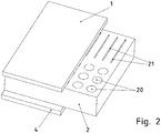
- FIG. 2 is a further embodiment of the invention outlined, wherein two variants of through recesses (20, 21) are shown
- FIG. 3 a further embodiment of the invention is shown, wherein a plurality of different sized heat sources are adapted.
- FIG. 1 is shown connected to one side of a first metal part 1, in particular aluminum part, a foam 2 or plastic, which has layers of metal paint 3.
- a further metal part 4 is connected.
- Foam layers that is to say plate-shaped structures, are immersed in the metal paint, in particular copper-containing paint, and then joined together, so that the in FIG. 1 shown layer structure arises.
- the application of the heat-conducting lacquer, in particular metal lacquer 3, to the plate-shaped structure can also be carried out in multiple layers, ie in several coating steps, a drying break being carried out between each coating step.
- spraying may also be used instead of or additionally subsequent to immersion.
- the respective coated structures are then connected to form the foam section 2 or loosely strung together.
- joining a locking, bonding, in particular using the paint, and / or screwing and / or pressing is advantageously carried out.
- the foam 2 is arranged as a poor heat conductor between the two metal parts (1, 4), but the metal paint 3 is due to the metallic portion of a good heat conductor.
- heat from the metal part 4 to the metal part 1 is passable and thus there is a lower heat transfer resistance between the metal part 4 and 1 than on the foam 2 or the environment.
- the gap between the metal parts 1 and 4 is filled with foam 2, so that vibrations are damped and electromagnetic emissions are attenuated in the metal coating layers 3 or the radiating transmitter is shielded.
- a heat source is arranged on the metal part 4, for example a heat-generating component.
- the metal part 1 need not be formed as a flat plate, but can also be embodied as a heat sink part, for example with cooling elements attached to its outer surface, such as cooling fins, cold fingers or other surface enlarging structures.
- a heat source for example, a power module can be used, which has a plurality of electronic power semiconductor switches, IGBT or MOSFET.
- the metal part 4 can be produced, for example, from aluminum or copper-containing metal.
- the foam 2 is provided with continuous round recesses 20 or cuboid through recesses 21.
- the foam section 2 immersed in metal paint, ie metal, especially copper, -containing paint. After being pulled out of the liquid paint and after the subsequent drying, the plastic section 2 is arranged between the metal parts 1 and 4. Thus, the plastic portion has through-contacted recesses, wherein the metal paint coating contacts the metal part 1 and 4 and transports heat.
- metal paint ie metal, especially copper, -containing paint.
- the foam between the provided as a heat sink or acting as a heat sink housing part metal part 1 and a component (30, 31) equipped printed circuit board 32 is provided, wherein it is the contour of a populated printed circuit board 32 following formed on the side facing away from the metal part 1 side ,
- a power component 30 is equipped on the circuit board 32, which generates a large amount of heat, but there are also smaller and / or other components 31 equipped, which generate heat.
- the circuit board 32 is flat. Since the components (30, 31) equipped on the same side have different heights, the foam 2 then has a correspondingly variable wall thickness.
- the metal part 4 is arranged on the component 30.
- varnish instead of varnish, another liquid can also be used in the production if curing is achievable in such a way that the thermally conductive layer described is produced.
- the negative image of the assembled printed circuit board 32 is formed in the foam 2 as an impression in the production of the foam 2.
- the foam 2 is used as a foam or plastic 2 EPS or EPP and / or the foam 2 has differently shaped recesses (20, 21).
- the recesses are also so thin executable that the paint is not partially or completely distributed by immersion in paint but by drawing into the recesses by capillary action in the recess.
- the parts of the multi-part plastic portion are then substantially spherical or at least round, in particular wherein the parts are polystyrene particles, in particular styrofoam beads.
- the coating then surrounds the particles in each case and thus forms a thermally conductive connection from the heat source to the heat sink.
- the coating material is electrically conductive, so that the heat sink can be arranged at the same potential as the heat source.
- an electrically insulating coating material is used so that the same potential is not provided.
Landscapes
- Engineering & Computer Science (AREA)
- Microelectronics & Electronic Packaging (AREA)
- Physics & Mathematics (AREA)
- Thermal Sciences (AREA)
- Chemical & Material Sciences (AREA)
- Chemical Kinetics & Catalysis (AREA)
- Combustion & Propulsion (AREA)
- Materials Engineering (AREA)
- Organic Chemistry (AREA)
- Cooling Or The Like Of Electrical Apparatus (AREA)
- Cooling Or The Like Of Semiconductors Or Solid State Devices (AREA)
Description
- Die Erfindung betrifft eine Anordnung zum Temperieren eines wärmeerzeugenden Bauteils und ein Verfahren zum Herstellen einer Anordnung.
- Es ist bekannt, ein wärmeerzeugendes Bauteil, wärmeleitend mit einem Kühlkörper zu verbinden.
- Aus der
US 2007/240310 A1 ist ein Wärmemanagementsystem bekannt. - Aus der
EP 2 273 859 A2 ist die Verwendung eines Steuermoduls für eine in einem Automatikgetriebe verbaute Getriebesteuerung bekannt. - Aus der
JP 8 238707 A - Aus der
EP 2 040 526 A2 ist ein Steuergerät für ein Kraftfahrzeug bekannt. - Der Erfindung liegt daher die Aufgabe zugrunde, eine Anordnung zum Temperieren eines wärmeerzeugenden Bauteils und ein Verfahren zum Herstellen einer solchen Anordnung weiterzubilden, wobei ein einfach herzustellendes und kostengünstiges Wärmetransportmittel geschaffen werden soll.
- Erfindungsgemäß wird die Aufgabe bei der Anordnung zum Temperieren eines wärmeerzeugenden Bauteils nach den in Anspruch 1 und bei dem Verfahren zum Herstellen einer Anordnung nach den in Anspruch 12 angegebenen Merkmalen gelöst.
- Wichtige Merkmale der Erfindung bei der Anordnung zum Temperieren eines wärmeerzeugenden Bauteils sind, dass die Anordnung zumindest einen Kunststoffabschnitt aufweist und ein Metallteil
- wobei der Kunststoffabschnitt zwischen dem Bauteil und dem ersten Metallteil angeordnet ist,
- wobei Kunststoffabschnitt eine oder mehrere Ausnehmungen aufweist, welche mit einem wärmeleitfähigen Beschichtungsmaterial beschichtet sind.
- Von Vorteil ist dabei, dass die Wärme des Bauteils, insbesondere direkt oder über ein zweites Metallteil, an das Beschichtungsmaterial leitbar ist, welches die Wärme dann weiter leitet und über einen Kontaktbereich zwischen erstem Metallteil und Beschichtungsmaterial an das erste Metallteil leitet, welches die Wärme dann an die Umgebung abgibt.
- Des Weiteren schützt der Kunststoff das Bauteil, da er dieses zumindest teilweise umgibt. Außerdem ist eine wärmetechnische Trennung des Bauteils von weiteren Bauteilen einfach ausgeführt. Somit sind Bauteile auf verschiedenem Temperaturniveau voneinander trennbar und über das Metallteil entwärmbar.
- Bei einer vorteilhaften Ausgestaltung ist die spezifische Wärmeleitfähigkeit des Beschichtungsmaterial mindestens 100 mal, insbesondere 1000 mal, besser als die spezifische Wärmeleitfähigkeit des Kunststoffs. Von Vorteil ist dabei, dass eine effektive Entwärmung ermöglicht ist.
- Bei einer vorteilhaften Ausgestaltung ist der Kunststoff ein Schaumstoff, insbesondere wobei der Kunststoff ein EPS oder ein EPP ist. Von Vorteil ist dabei, dass eine einfache kostengünstige Herstellung ermöglicht ist.
- Bei einer vorteilhaften Ausgestaltung ist der Kunststoffabschnitt mehrteilig ausgeführt, wobei jeweils zwischen zwei Teilen eine jeweilige Schicht des Beschichtungsmaterials angeordnet ist. Von Vorteil ist dabei, dass ein schichtartiger Aufbau in einfacher Weise herstellbar ist, indem die Schichtteile separat lackiert werden und dann zusammengefügt werden.
- Bei einer vorteilhaften Ausgestaltung sind die Ausnehmungen durchgehend, insbesondere von der dem Metallteil zugewandten Seite bis zu der dem Bauteil zugewandten Seite des Kunststoffabschnitts, ausgeführt und sind vollständig mit Beschichtungsmaterial ausgefüllt oder zumindest an der die Ausnehmung begrenzenden Wandung des Kunststoffabschnitts mit Beschichtungsmaterial beschichtet. Von Vorteil ist dabei, dass bei durchkontaktierten Ausnehmungen die Wärme auf dem kürzesten Weg transportierbar ist von dem wärmeerzeugenden Bauteil zu dem Kühlkörper. Außerdem ist Masse für den Wärmetransport einsparbar, indem nur die Wandung der Ausnehmungen mit Metall beschichtbar sind.
- Bei einer vorteilhaften Ausgestaltung weist das Beschichtungsmaterial eine Lackschicht ist, also durch Auftragen von Lack hergestellt ist und/oder durch Eintauchen von Lack. Von Vorteil ist dabei, dass eine einfache Herstellung der Metallschicht durch Lackieren erreichbar ist. Denn hierzu ist nur ein Eintauchen in einen Lack notwendig.
- Bei einer vorteilhaften Ausgestaltung sind die Ausnehmungen derart dünn, dass beim Herstellen Lack mittels Kapillarkraft die Ausnehmungen zumindest teilweise befüllt. Von Vorteil ist dabei, dass das Kunststoffteil nicht untergetaucht werden muss in den Lack sondern dass ein teilweises Eintauchen oder wenigstens Berühren des flüssigen Lacks bei der Herstellung ausreicht. Denn unter Kapillarkraftwirkung wird der flüssige Lack in die Ausnehmungen eingezogen. Bei geeigneter Materialwahl des Kunststoffs und des Lacks ist die relative Oberflächenspannung reduzierbar, so dass ein schnelles und selbsttätiges Einziehen des Lacks in die dünnen als Ausnehmungen fungierenden Spalte ermöglicht ist.
- Bei einer vorteilhaften Ausgestaltung sind die Ausnehmungen zylindrisch oder quaderförmig ausgeführt. Von Vorteil ist dabei, dass eine einfache Herstellung ermöglicht ist.
- Wichtige Merkmale bei dem Verfahren zum Herstellen einer Anordnung zum Temperieren eines wärmeerzeugenden Bauteils sind, dass
- - ein Kunststoffabschnitt in ein Lackbad eingetaucht wird oder Lack auf den Kunststoffabschnitt aufgetragen und/oder aufgesprüht wird und/oder mittels Kapillarkräften Lack auf den Kunststoffabschnitt gezogen wird, so dass der Kunststoffabschnitt eine oder mehrere Ausnehmungen aufweist, welche mit einem wärmeleitfähigen Beschichtungsmaterial beschichtet sind,
- - der Kunststoffabschnitt zwischen Bauteil und einem Metallteil, insbesondere Kühlkörper angeordnet wird.
- Von Vorteil ist dabei, dass eine einfach herstellbare Entwärmung in einem Gerät herstellbar ist, wobei die wärmeerzeugenden Bauteile mit dem Kunststoffteil in Berührung bringbar sind, so dass sie nicht nur entwärmbar sondern auch mechanisch geschützt sind. Der Kunststoff übernimmt somit auch teilweise gehäusebildende Funktion, insbesondere beim Lagern einer Leiterplatte in einem Lager, wo der Kunststoff schon um die Leiterplatte mit den wärmeerzeugenden Bauteilen herum vorsehbar ist. Somit ist die im Lager gelagerte Leiterplatte geschützt. Das gesamte aus Leiterplatte und Kunststoff bestehende Modul wird als Einheit ausgeführt und bei der Herstellung des Elektrogeräts, insbesondere Umrichters, in ein Gehäuse eingeschoben und somit auch bei der Herstellung als die Leiterplatte schützendes Teil verwendet.
- Bei einer vorteilhaften Ausgestaltung wird das Bauteil mit weiteren Bauteilen auf einer Leiterplatte bestückt angeordnet und in den Kunststoffabschnitt wird ein Abdruck der mit Bauteilen bestückten Leiterplatte einhüllenden Kontur eingedrückt. Von Vorteil ist dabei, dass das Kunststoffteil der Einhüllenden der Oberfläche der bestückten Leiterplatte folgend geformt ist. Dabei ist ein Hinterschnitt nicht ausfüllbar sondern nur die Einhüllende ausformbar, also derjenige Abdruck ausformbar, welcher zurückbleibt, wenn die bestückte Leiterplatte in den Kunststoffabschnitt eingerückt wird, also in linearer Richtung hineinbewegt und wieder zurückgezogen wird.
- Bei einer vorteilhaften Ausgestaltung wird der Kunststoffabschnitt aus mehreren Teilen zusammengesetzt, die jeweils mit dem Beschichtungsmaterial beschichtet sind. Von Vorteil ist dabei, dass ein Schichtaufbau des Kunststoffabschnitts ausführbar ist, wobei jedes Einzelsegment beschichtet ausgeführt ist und somit nach Zusammensetzen ein Sandwichartiger Aufbau erreichbar ist und damit ein effektive Entwärmung der wärmeerzeugenden Teile, die auch breiter sein dürfen als die Wandstärke eines jeweiligen Einzelsegments.
- Die Erfindung wird nun anhand von schematischen Abbildungen näher erläutert:
- In der
Figur 1 ist eine erfindungsgemäße Ausführungsform schematisch skizziert. - In der
Figur 2 ist eine weitere erfindungsgemäße Ausführungsform skizziert, wobei zwei Varianten von durchgehenden Ausnehmungen (20, 21) gezeigt sind - In der
Figur 3 ist eine weitere erfindungsgemäße Ausführungsform gezeigt, wobei mehrere verschieden große Wärmequellen adaptiert sind. - Wie in
Figur 1 gezeigt, ist an einer Seite eines ersten Metallteils 1, insbesondere Aluminiumteil, ein Schaumstoff 2 oder Kunststoff verbunden, welcher Schichten von Metalllack 3 aufweist. An der vom ersten Metallteil 1 abgewandten Seite des Schaumstoffs 2 ist ein weiteres Metallteil 4 verbunden. - Zur Herstellung werden dabei Schaumstoffschichten, also plattenförmige Gebilde in den Metalllack, insbesondere also Kupfer-haltigen Lack, eingetaucht und danach zusammengefügt, so dass die in
Figur 1 gezeigte Schichtstruktur entsteht. - Die Auftragung des wärmeleitenden Lacks, insbesondere Metalllacks 3, auf die plattenförmige Gebilde ist auch mehrschichtig ausführbar, also in mehreren Beschichtungsschritten, wobei zwischen jedem Beschichtungsschritt ein Trocknungspause ausgeführt wird. Zum Auftragen des Lacks ist auch ein Sprühen anstatt oder zusätzlich nachfolgend zum Eintauchen anwendbar.
- Die jeweils beschichteten Gebilde werden dann zur Bildung des Schaumstoffabschnitts 2 verbunden oder lose aneinander gereiht. Beim Verbinden ist ein Verrasten, Verkleben, insbesondere unter Verwendung des Lacks, und/oder Verschrauben und/oder Verpressen vorteilhaft ausführbar.
- Somit ist zwar der Schaumstoff 2 als schlechter Wärmeleiter zwischen den beiden Metallteilen (1, 4) angeordnet, aber der Metalllack 3 ist infolge des metallischen Anteils ein guter Wärmeleiter. Somit wird Wärme vom Metallteil 4 zum Metallteil 1 durchleitbar und es besteht also ein geringerer Wärmeübergangswiderstand zwischen Metallteil 4 und 1 als über den Schaumstoff 2 oder die Umgebung.
- Auf diese Weise ist der Zwischenraum zwischen den Metallteilen 1 und 4 befüllt mit Schaumstoff 2, so dass Schwingungen abgedämpft werden und elektromagnetische Abstrahlungen in den Metalllackschichten 3 gedämpft werden beziehungsweise der strahlende Sender abgeschirmt wird.
- Vorteiligerweise ist am Metallteil 4 eine Wärmequelle angeordnet, beispielsweise ein wärmeerzeugendes Bauteil. Das Metallteil 1 muss nicht als ebene Platte geformt sein, sondern ist auch als Kühlkörperteil ausführbar, beispielsweise mit an seiner Außenoberfläche angebrachten Kühlelementen, wie Kühlrippen, Kühlfingern oder anderen oberflächenvergrößernden Strukturen.
- Als Wärmequelle ist beispielsweise ein Leistungsmodul verwendbar, welches mehrere elektronische Leistungshalbleiterschalter, IGBT oder MOSFET, aufweist. Das Metallteil 4 ist beispielsweise aus Aluminium oder Kupfer-haltigem Metall herstellbar.
- Wie in
Figur 2 gezeigt, ist der Schaumstoff 2 mit durchgehenden runden Ausnehmungen 20 oder quaderförmigen durchgehenden Ausnehmungen 21 versehen. - Zur Herstellung werden in einen großen Schaumstoffabschnitt die Ausnehmungen eingebracht und danach der Schaumstoffabschnitt 2 eingetaucht in Metalllack, also Metall-, insbesondere Kupfer-, -haltigen Lack. Nach dem Herausziehen aus dem flüssigen Lack und nach dem nachfolgenden Abtrocknen wird der Kunststoffabschnitt 2 zwischen die Metallteil 1 und 4 angeordnet. Somit weist der Kunststoffabschnitt durchkontaktierte Ausnehmungen auf, wobei die Metalllackbeschichtung die Metallteil 1 und 4 berührt und Wärme transportiert.
- Wie in
Figur 3 gezeigt ist der Schaumstoff zwischen dem als Kühlkörper oder dem als als Kühlkörper fungierenden Gehäuseteil vorgesehenen Metallteil 1 und einer mit Bauteilen (30, 31) bestückten Leiterplatte 32 vorgesehen, wobei er der Kontur einer bestückten Leiterplatte 32 folgend auf der vom Metallteil 1 abgewandten Seite geformt ist. - Dabei ist auf der Leiterplatte 32 nicht nur ein Leistungsbauteil 30 bestückt, welches eine große Wärmemenge erzeugt, sondern es sind auch kleinere und/oder andere Bauteile 31 bestückt, welche Wärme erzeugen.
- Die Leiterplatte 32 ist eben ausgeführt. Da die auf derselben Seite bestückten Bauteile (30, 31) verschieden hoch sind, weist der Schaumstoff 2 dann entsprechend veränderliche Wandstärke auf.
- Zur Aufspreizung der Temperatur und Vergleichmäßigung schwankender Wärmestromstärken, ist das Metallteil 4 auf dem Bauteil 30 angeordnet.
- Statt Lack ist auch eine andere Flüssigkeit bei der Herstellung verwendbar, wenn ein Aushärten derart erreichbar ist, dass die beschriebene wärmeleitfähige Schicht hergestellt ist.
- Bei weiteren erfindungsgemäßen Ausführungsbeispielen wird bei der Herstellung des Schaumstoffs 2 das Negativbild der bestückten Leiterplatte 32 in den Schaumstoff 2 als Abdruck eingeformt. Somit ist ein besonders einfaches und wenig aufwendiges Fügen des Schaumstoffabschnitts 2 beim Einbau in die erfindungsgemäße Anordnung ermöglicht.
- Bei weiteren erfindungsgemäßen Ausführungsbeispielen wird als Schaumstoff oder Kunststoff 2 EPS oder EPP verwendet und/oder der Schaumstoff 2 weist unterschiedlich geformte Ausnehmungen (20, 21) auf. Statt der obengenannten Durchkontaktierung, wobei nur die Oberfläche der Ausnehmung beschichtet ist, ist auch ein volles Befüllen der Ausnehmungen (20, 21) ermöglicht. In Weiterbildung sind die Ausnehmungen auch derart dünn ausführbar, dass der Lack nicht durch Untertauchen in Lack sondern durch Einziehen in die Ausnehmungen mittels Kapillarwirkung in der Ausnehmung teilweise oder ganz verteilt wird.
- Bei weiteren erfindungsgemäßen Ausführungsbeispielen wird ist als Schaumstoff oder mehrteiliger Kunststoff Styropor verwendet, wobei die Teile des mehrteiligen Kunststoffabschnitts dann im Wesentlichen kugelförmig oder zumindest rund sind, insbesondere wobei die Teile Styropor-Partikel sind, insbesondere Styroporkügelchen. Die Beschichtung umgibt dann die Partikel jeweils und bildet somit eine wärmeleitfähige Verbindung von der Wärmequelle zum Kühlkörper.
- Bei weiteren erfindungsgemäßen Ausführungsbeispielen ist das Beschichtungsmaterial elektrisch leitfähig, so dass der Kühlkörper auf dem gleichen Potential wie die Wärmequelle anordenbar ist. Alternativ wird ein elektrisch isolierendes Beschichtungsmaterial verwendet, so dass nicht das gleiche Potential vorzusehen ist.
-
- 1 Metallteil, insbesondere Aluminiumteil
- 2 Schaumstoff oder Kunststoff
- 3 Metalllack
- 4 Metallteil
- 20 Ausnehmung, insbesondere durchgehend
- 21 Ausnehmung, insbesondere durchgehend
- 30 Leistungsbauteil
- 31 Bauteil, insbesondere wärmeerzeugendes
- 32 Leiterplatte
Claims (13)
- Anordnung zum Temperieren eines wärmeerzeugenden Bauteils,
wobei die Anordnung zumindest einen Kunststoffabschnitt aufweist und ein Metallteil (1, 4)
wobei der Kunststoffabschnitt zwischen dem Bauteil und dem Metallteil (1, 4) angeordnet ist,
wobei- Kunststoffabschnitt eine oder mehrere Ausnehmungen (20, 21) aufweist, welche mit einem Beschichtungsmaterial, insbesondere mit einem wärmeleitfähigen Beschichtungsmaterial, beschichtet sind, wobei das Beschichtungsmaterial wärmeleitfähiger als der Kunststoff ist,- und/oder dass der Kunststoffabschnitt mehrteilig ausgeführt ist, wobei jeweils zwischen zwei Teilen eine jeweilige Schicht eines Beschichtungsmaterials, insbesondere eines wärmeleitfähigen Beschichtungsmaterials, angeordnet ist, wobei das Beschichtungsmaterial wärmeleitfähiger als der Kunststoff ist,insbesondere wobei das Beschichtungsmaterial elektrisch leitfähig oder isolierend ist,
dadurch gekennzeichnet, dass
der Kunststoff ein Schaumstoff (2) ist, insbesondere wobei der Kunststoff ein EPS oder ein EPP ist
wobei der Kunststoffabschnitt mehrteilig ausgeführt ist, wobei jeweils zwischen zwei Teilen eine jeweilige Schicht eines wärmeleitfähigen Beschichtungsmaterials angeordnet ist
wobei die Ausnehmungen (20, 21) durchgehend, von der dem Metallteil (1, 4) zugewandten Seite bis zu der dem Bauteil zugewandten Seite des Kunststoffabschnitts ausgeführt sind und vollständig mit Beschichtungsmaterial ausgefüllt sind oder zumindest an der die Ausnehmung (20, 21) begrenzenden Wandung des Kunststoffabschnitts mit Beschichtungsmaterial beschichtet sind. - Anordnung nach Anspruch 1,
dadurch gekennzeichnet, dass
die spezifische Wärmeleitfähigkeit des Beschichtungsmaterial mindestens 100 mal, insbesondere mindestens 1000 mal, höher ist als die spezifische Wärmeleitfähigkeit des Kunststoffs. - Anordnung nach mindestens einem der vorangegangenen Ansprüche,
dadurch gekennzeichnet, dass
die Teile des mehrteiligen Kunststoffabschnitts kugelförmig oder zumindest rund sind, insbesondere wobei die Teile Styropor-Partikel sind, insbesondere Styroporkügelchen. - Anordnung nach mindestens einem der vorangegangenen Ansprüche,
dadurch gekennzeichnet, dass
das Beschichtungsmaterial eine Lackschicht ist, also durch Auftragen von Lack (3) hergestellt ist und/oder durch Eintauchen von Lack (3). - Anordnung nach mindestens einem der vorangegangenen Ansprüche,
dadurch gekennzeichnet, dass
die Ausnehmungen (20, 21) derart dünn sind, dass beim Herstellen Lack (3) mittels Kapillarkraft die Ausnehmungen (20, 21) zumindest teilweise befüllt. - Anordnung nach mindestens einem der vorangegangenen Ansprüche,
dadurch gekennzeichnet, dass
die Ausnehmungen (20, 21) zylindrisch oder quaderförmig ausgeführt sind. - Anordnung nach mindestens einem der vorangegangenen Ansprüche,
dadurch gekennzeichnet, dass
als Beschichtungsmaterial einen wärmeleitfähigen Stoff, wie Metall oder Keramik, enthaltender Lack (3), insbesondere ein Kupfer oder Keramik, enthaltender Lack (3), verwendet ist,
insbesondere wobei der Stoff als Pulver dem Lack (3) beigemischt ist. - Anordnung nach mindestens einem der vorangegangenen Ansprüche,
dadurch gekennzeichnet, dass
statt Lack (3) eine andere aushärtende Flüssigkeit bei der Herstellung verwendet ist. - Verfahren zum Herstellen einer Anordnung, insbesondere nach mindestens einem der vorangegangenen Ansprüche, zum Temperieren eines wärmeerzeugenden Bauteils,
dadurch gekennzeichnet, dass- ein Kunststoffabschnitt in ein Lackbad eingetaucht wird oder Lack (3) auf den Kunststoffabschnitt aufgetragen und/oder aufgesprüht wird und/oder mittels Kapillarkräften Lack (3) auf den Kunststoffabschnitt gezogen wird, so dass der Kunststoffabschnitt eine oder mehrere Ausnehmungen (20, 21) aufweist, welche mit einem wärmeleitfähigen Beschichtungsmaterial beschichtet sind,- der Kunststoffabschnitt zwischen Bauteil und einem Metallteil (1, 4), insbesondere Kühlkörper angeordnet wird,wobei das Bauteil mit weiteren Bauteilen auf einer Leiterplatte (32) bestückt angeordnet wird und in den Kunststoffabschnitt ein Abdruck der mit Bauteilen bestückten Leiterplatte (32) einhüllenden Kontur eingedrückt wird. - Verfahren nach Anspruch 9,
dadurch gekennzeichnet, dass
der Kunststoffabschnitt aus mehreren Teilen zusammengesetzt wird, die jeweils mit dem Beschichtungsmaterial beschichtet sind. - Verfahren nach Anspruch 9 oder 10,
dadurch gekennzeichnet, dass
die Teile des mehrteiligen Kunststoffabschnitts kugelförmig oder zumindest rund sind. - Verfahren nach Anspruch 9, 10 oder 11,
dadurch gekennzeichnet, dass
durch das Auftragen von Lack (3) und/oder das Eintauchen von Lack (3) eine Lackschicht als Beschichtungsmaterial erzeugt wird. - Verfahren nach Anspruch 9, 10, 11 oder 12,
dadurch gekennzeichnet, dass
die Ausnehmungen (20, 21) derart dünn und der Lack (3) derart ausgewählt sind, dass beim Herstellen Lack (3) mittels Kapillarkraft die Ausnehmungen (20, 21) zumindest teilweise befüllt.
Applications Claiming Priority (2)
| Application Number | Priority Date | Filing Date | Title |
|---|---|---|---|
| DE102011015912.6A DE102011015912B4 (de) | 2011-04-01 | 2011-04-01 | Anordnung zum Temperieren für Wärme erzeugende elektrische Bauteile und Verfahren zum Herstellen einer Kühlanordnung für elektrische Bauteile |
| PCT/EP2012/001055 WO2012130382A1 (de) | 2011-04-01 | 2012-03-09 | Anordnung zum temperieren eines wärmeerzeugenden bauteils und verfahren zum herstellen einer anordnung |
Publications (2)
| Publication Number | Publication Date |
|---|---|
| EP2695503A1 EP2695503A1 (de) | 2014-02-12 |
| EP2695503B1 true EP2695503B1 (de) | 2017-10-18 |
Family
ID=45855690
Family Applications (1)
| Application Number | Title | Priority Date | Filing Date |
|---|---|---|---|
| EP12709518.0A Active EP2695503B1 (de) | 2011-04-01 | 2012-03-09 | Anordnung zum temperieren eines wärmeerzeugenden bauteils und verfahren zum herstellen einer anordnung |
Country Status (3)
| Country | Link |
|---|---|
| EP (1) | EP2695503B1 (de) |
| DE (1) | DE102011015912B4 (de) |
| WO (1) | WO2012130382A1 (de) |
Families Citing this family (1)
| Publication number | Priority date | Publication date | Assignee | Title |
|---|---|---|---|---|
| DE102013215367A1 (de) * | 2013-08-05 | 2015-02-05 | Zf Friedrichshafen Ag | Elektronisches Schaltungsmodul |
Family Cites Families (6)
| Publication number | Priority date | Publication date | Assignee | Title |
|---|---|---|---|---|
| JP3075132B2 (ja) * | 1995-03-06 | 2000-08-07 | 信越化学工業株式会社 | 放熱シート |
| DE10101359A1 (de) * | 2001-01-13 | 2002-07-25 | Conti Temic Microelectronic | Verfahren zur Herstellung einer elektronischen Baugruppe |
| US7797808B2 (en) | 2005-10-11 | 2010-09-21 | General Electric Company | Thermal management system and associated method |
| JP4897360B2 (ja) * | 2006-06-08 | 2012-03-14 | ポリマテック株式会社 | 熱伝導性成形体及びその製造方法 |
| DE102007029913A1 (de) * | 2007-06-28 | 2009-01-02 | Robert Bosch Gmbh | Elektrisches Steuergerät |
| DE102007045261A1 (de) * | 2007-09-21 | 2009-04-23 | Continental Automotive Gmbh | Elektrisches Gerät, insbesondere Steuergerät für ein Kraftfahrzeug |
-
2011
- 2011-04-01 DE DE102011015912.6A patent/DE102011015912B4/de active Active
-
2012
- 2012-03-09 EP EP12709518.0A patent/EP2695503B1/de active Active
- 2012-03-09 WO PCT/EP2012/001055 patent/WO2012130382A1/de not_active Ceased
Non-Patent Citations (1)
| Title |
|---|
| None * |
Also Published As
| Publication number | Publication date |
|---|---|
| DE102011015912A1 (de) | 2012-10-04 |
| EP2695503A1 (de) | 2014-02-12 |
| WO2012130382A1 (de) | 2012-10-04 |
| DE102011015912B4 (de) | 2022-03-17 |
Similar Documents
| Publication | Publication Date | Title |
|---|---|---|
| DE112015003987B4 (de) | Schaltungsbaugruppe, elektrischer Verteiler und Herstellungsverfahren für eine Schaltungsbaugruppe | |
| DE112015004024B4 (de) | Schaltungsbaugruppe und elektrischer Verteiler | |
| DE102007057533B4 (de) | Kühlkörper, Verfahren zur Herstellung eines Kühlkörpers und Leiterplatte mit Kühlkörper | |
| DE19855389C2 (de) | Elektronische Vorrichtung | |
| DE112015005727T5 (de) | Schaltungsanordnung und elektrischer Verteiler | |
| DE19910500A1 (de) | Elektrisches Gerät | |
| WO2012104017A1 (de) | Elektrisches gerät | |
| DE112015002430T5 (de) | Schaltungsbaugruppe und elektrischer Verteiler | |
| DE102015207893B3 (de) | Elektronische Baugruppe, insbesondere für ein Getriebesteuermodul | |
| DE102015001148A1 (de) | Anordnung und Verfahren zur elektromagnetischen Abschirmung | |
| DE102011085170A1 (de) | Steuermodul mit verklebter Trägerplatte | |
| EP3167480B1 (de) | Kühlvorrichtung, verfahren zur herstellung einer kühlvorrichtung und leistungsschaltung | |
| EP3289839B1 (de) | Elektronische baugruppe, insbesondere für ein getriebesteuermodul | |
| DE102012206505A1 (de) | Elektronische vorrichtung mit einer leiterplatte mit wärmeabführungsstruktur | |
| DE102012216918A1 (de) | Ölwanne mit zumindest zweiteiligem Ölwannengehäuse | |
| DE102022213806A1 (de) | Kühlanordnung, Steuereinrichtung, Steuereinrichtungssystem und Herstellungsverfahren | |
| DE102011015912B4 (de) | Anordnung zum Temperieren für Wärme erzeugende elektrische Bauteile und Verfahren zum Herstellen einer Kühlanordnung für elektrische Bauteile | |
| EP3016485A2 (de) | Elektrisches gerät für den einsatz in einem kontaminierenden medium und verfahren zur herstellung eines solchen | |
| DE102014205958A1 (de) | Halbleiterschaltelementanordnung und Steuergeräteinrichtung für ein Fahrzeug | |
| WO1998028790A1 (de) | Montageanordnung eines halbleiterbauelements auf einer leiterplatte | |
| WO2020064350A1 (de) | Verfahren für eine montage eines elektrischen geräts und zugehöriges elektrisches gerät | |
| WO2018050382A1 (de) | Elektronische baugruppe, insbesondere für ein getriebesteuermodul, und verfahren zum herstellen einer elektronischen baugruppe | |
| DE102019126311B3 (de) | Stromleitendes Kühlelement, System und Verfahren zur Wärmeabführung von leistungselektronischen Bauteilen auf Platinen | |
| DE102015218973A1 (de) | Elektronische Baugruppe, insbesondere für ein Getriebesteuermodul | |
| DE102011010434B4 (de) | Elektrisches Gerät |
Legal Events
| Date | Code | Title | Description |
|---|---|---|---|
| PUAI | Public reference made under article 153(3) epc to a published international application that has entered the european phase |
Free format text: ORIGINAL CODE: 0009012 |
|
| 17P | Request for examination filed |
Effective date: 20131104 |
|
| AK | Designated contracting states |
Kind code of ref document: A1 Designated state(s): AL AT BE BG CH CY CZ DE DK EE ES FI FR GB GR HR HU IE IS IT LI LT LU LV MC MK MT NL NO PL PT RO RS SE SI SK SM TR |
|
| DAX | Request for extension of the european patent (deleted) | ||
| GRAP | Despatch of communication of intention to grant a patent |
Free format text: ORIGINAL CODE: EPIDOSNIGR1 |
|
| INTG | Intention to grant announced |
Effective date: 20170601 |
|
| GRAS | Grant fee paid |
Free format text: ORIGINAL CODE: EPIDOSNIGR3 |
|
| GRAA | (expected) grant |
Free format text: ORIGINAL CODE: 0009210 |
|
| AK | Designated contracting states |
Kind code of ref document: B1 Designated state(s): AL AT BE BG CH CY CZ DE DK EE ES FI FR GB GR HR HU IE IS IT LI LT LU LV MC MK MT NL NO PL PT RO RS SE SI SK SM TR |
|
| REG | Reference to a national code |
Ref country code: GB Ref legal event code: FG4D Free format text: NOT ENGLISH |
|
| REG | Reference to a national code |
Ref country code: CH Ref legal event code: EP |
|
| REG | Reference to a national code |
Ref country code: AT Ref legal event code: REF Ref document number: 938980 Country of ref document: AT Kind code of ref document: T Effective date: 20171115 Ref country code: IE Ref legal event code: FG4D Free format text: LANGUAGE OF EP DOCUMENT: GERMAN |
|
| REG | Reference to a national code |
Ref country code: DE Ref legal event code: R096 Ref document number: 502012011474 Country of ref document: DE |
|
| REG | Reference to a national code |
Ref country code: NL Ref legal event code: MP Effective date: 20171018 |
|
| REG | Reference to a national code |
Ref country code: FR Ref legal event code: PLFP Year of fee payment: 7 |
|
| REG | Reference to a national code |
Ref country code: LT Ref legal event code: MG4D |
|
| PG25 | Lapsed in a contracting state [announced via postgrant information from national office to epo] |
Ref country code: NL Free format text: LAPSE BECAUSE OF FAILURE TO SUBMIT A TRANSLATION OF THE DESCRIPTION OR TO PAY THE FEE WITHIN THE PRESCRIBED TIME-LIMIT Effective date: 20171018 |
|
| PG25 | Lapsed in a contracting state [announced via postgrant information from national office to epo] |
Ref country code: LT Free format text: LAPSE BECAUSE OF FAILURE TO SUBMIT A TRANSLATION OF THE DESCRIPTION OR TO PAY THE FEE WITHIN THE PRESCRIBED TIME-LIMIT Effective date: 20171018 Ref country code: FI Free format text: LAPSE BECAUSE OF FAILURE TO SUBMIT A TRANSLATION OF THE DESCRIPTION OR TO PAY THE FEE WITHIN THE PRESCRIBED TIME-LIMIT Effective date: 20171018 Ref country code: ES Free format text: LAPSE BECAUSE OF FAILURE TO SUBMIT A TRANSLATION OF THE DESCRIPTION OR TO PAY THE FEE WITHIN THE PRESCRIBED TIME-LIMIT Effective date: 20171018 Ref country code: NO Free format text: LAPSE BECAUSE OF FAILURE TO SUBMIT A TRANSLATION OF THE DESCRIPTION OR TO PAY THE FEE WITHIN THE PRESCRIBED TIME-LIMIT Effective date: 20180118 Ref country code: SE Free format text: LAPSE BECAUSE OF FAILURE TO SUBMIT A TRANSLATION OF THE DESCRIPTION OR TO PAY THE FEE WITHIN THE PRESCRIBED TIME-LIMIT Effective date: 20171018 |
|
| PG25 | Lapsed in a contracting state [announced via postgrant information from national office to epo] |
Ref country code: IS Free format text: LAPSE BECAUSE OF FAILURE TO SUBMIT A TRANSLATION OF THE DESCRIPTION OR TO PAY THE FEE WITHIN THE PRESCRIBED TIME-LIMIT Effective date: 20180218 Ref country code: RS Free format text: LAPSE BECAUSE OF FAILURE TO SUBMIT A TRANSLATION OF THE DESCRIPTION OR TO PAY THE FEE WITHIN THE PRESCRIBED TIME-LIMIT Effective date: 20171018 Ref country code: LV Free format text: LAPSE BECAUSE OF FAILURE TO SUBMIT A TRANSLATION OF THE DESCRIPTION OR TO PAY THE FEE WITHIN THE PRESCRIBED TIME-LIMIT Effective date: 20171018 Ref country code: GR Free format text: LAPSE BECAUSE OF FAILURE TO SUBMIT A TRANSLATION OF THE DESCRIPTION OR TO PAY THE FEE WITHIN THE PRESCRIBED TIME-LIMIT Effective date: 20180119 Ref country code: HR Free format text: LAPSE BECAUSE OF FAILURE TO SUBMIT A TRANSLATION OF THE DESCRIPTION OR TO PAY THE FEE WITHIN THE PRESCRIBED TIME-LIMIT Effective date: 20171018 Ref country code: BG Free format text: LAPSE BECAUSE OF FAILURE TO SUBMIT A TRANSLATION OF THE DESCRIPTION OR TO PAY THE FEE WITHIN THE PRESCRIBED TIME-LIMIT Effective date: 20180118 |
|
| REG | Reference to a national code |
Ref country code: DE Ref legal event code: R097 Ref document number: 502012011474 Country of ref document: DE |
|
| PG25 | Lapsed in a contracting state [announced via postgrant information from national office to epo] |
Ref country code: CZ Free format text: LAPSE BECAUSE OF FAILURE TO SUBMIT A TRANSLATION OF THE DESCRIPTION OR TO PAY THE FEE WITHIN THE PRESCRIBED TIME-LIMIT Effective date: 20171018 Ref country code: SK Free format text: LAPSE BECAUSE OF FAILURE TO SUBMIT A TRANSLATION OF THE DESCRIPTION OR TO PAY THE FEE WITHIN THE PRESCRIBED TIME-LIMIT Effective date: 20171018 Ref country code: EE Free format text: LAPSE BECAUSE OF FAILURE TO SUBMIT A TRANSLATION OF THE DESCRIPTION OR TO PAY THE FEE WITHIN THE PRESCRIBED TIME-LIMIT Effective date: 20171018 Ref country code: DK Free format text: LAPSE BECAUSE OF FAILURE TO SUBMIT A TRANSLATION OF THE DESCRIPTION OR TO PAY THE FEE WITHIN THE PRESCRIBED TIME-LIMIT Effective date: 20171018 |
|
| PLBE | No opposition filed within time limit |
Free format text: ORIGINAL CODE: 0009261 |
|
| STAA | Information on the status of an ep patent application or granted ep patent |
Free format text: STATUS: NO OPPOSITION FILED WITHIN TIME LIMIT |
|
| PG25 | Lapsed in a contracting state [announced via postgrant information from national office to epo] |
Ref country code: RO Free format text: LAPSE BECAUSE OF FAILURE TO SUBMIT A TRANSLATION OF THE DESCRIPTION OR TO PAY THE FEE WITHIN THE PRESCRIBED TIME-LIMIT Effective date: 20171018 Ref country code: SM Free format text: LAPSE BECAUSE OF FAILURE TO SUBMIT A TRANSLATION OF THE DESCRIPTION OR TO PAY THE FEE WITHIN THE PRESCRIBED TIME-LIMIT Effective date: 20171018 Ref country code: IT Free format text: LAPSE BECAUSE OF FAILURE TO SUBMIT A TRANSLATION OF THE DESCRIPTION OR TO PAY THE FEE WITHIN THE PRESCRIBED TIME-LIMIT Effective date: 20171018 Ref country code: PL Free format text: LAPSE BECAUSE OF FAILURE TO SUBMIT A TRANSLATION OF THE DESCRIPTION OR TO PAY THE FEE WITHIN THE PRESCRIBED TIME-LIMIT Effective date: 20171018 |
|
| 26N | No opposition filed |
Effective date: 20180719 |
|
| PG25 | Lapsed in a contracting state [announced via postgrant information from national office to epo] |
Ref country code: MT Free format text: LAPSE BECAUSE OF FAILURE TO SUBMIT A TRANSLATION OF THE DESCRIPTION OR TO PAY THE FEE WITHIN THE PRESCRIBED TIME-LIMIT Effective date: 20171018 |
|
| REG | Reference to a national code |
Ref country code: CH Ref legal event code: PL |
|
| PG25 | Lapsed in a contracting state [announced via postgrant information from national office to epo] |
Ref country code: SI Free format text: LAPSE BECAUSE OF FAILURE TO SUBMIT A TRANSLATION OF THE DESCRIPTION OR TO PAY THE FEE WITHIN THE PRESCRIBED TIME-LIMIT Effective date: 20171018 Ref country code: MC Free format text: LAPSE BECAUSE OF FAILURE TO SUBMIT A TRANSLATION OF THE DESCRIPTION OR TO PAY THE FEE WITHIN THE PRESCRIBED TIME-LIMIT Effective date: 20171018 |
|
| REG | Reference to a national code |
Ref country code: BE Ref legal event code: MM Effective date: 20180331 |
|
| REG | Reference to a national code |
Ref country code: IE Ref legal event code: MM4A |
|
| PG25 | Lapsed in a contracting state [announced via postgrant information from national office to epo] |
Ref country code: LU Free format text: LAPSE BECAUSE OF NON-PAYMENT OF DUE FEES Effective date: 20180309 |
|
| PG25 | Lapsed in a contracting state [announced via postgrant information from national office to epo] |
Ref country code: IE Free format text: LAPSE BECAUSE OF NON-PAYMENT OF DUE FEES Effective date: 20180309 |
|
| PG25 | Lapsed in a contracting state [announced via postgrant information from national office to epo] |
Ref country code: CH Free format text: LAPSE BECAUSE OF NON-PAYMENT OF DUE FEES Effective date: 20180331 Ref country code: BE Free format text: LAPSE BECAUSE OF NON-PAYMENT OF DUE FEES Effective date: 20180331 Ref country code: LI Free format text: LAPSE BECAUSE OF NON-PAYMENT OF DUE FEES Effective date: 20180331 |
|
| REG | Reference to a national code |
Ref country code: AT Ref legal event code: MM01 Ref document number: 938980 Country of ref document: AT Kind code of ref document: T Effective date: 20180309 |
|
| PG25 | Lapsed in a contracting state [announced via postgrant information from national office to epo] |
Ref country code: AT Free format text: LAPSE BECAUSE OF NON-PAYMENT OF DUE FEES Effective date: 20180309 |
|
| PG25 | Lapsed in a contracting state [announced via postgrant information from national office to epo] |
Ref country code: TR Free format text: LAPSE BECAUSE OF FAILURE TO SUBMIT A TRANSLATION OF THE DESCRIPTION OR TO PAY THE FEE WITHIN THE PRESCRIBED TIME-LIMIT Effective date: 20171018 |
|
| PG25 | Lapsed in a contracting state [announced via postgrant information from national office to epo] |
Ref country code: HU Free format text: LAPSE BECAUSE OF FAILURE TO SUBMIT A TRANSLATION OF THE DESCRIPTION OR TO PAY THE FEE WITHIN THE PRESCRIBED TIME-LIMIT; INVALID AB INITIO Effective date: 20120309 Ref country code: PT Free format text: LAPSE BECAUSE OF FAILURE TO SUBMIT A TRANSLATION OF THE DESCRIPTION OR TO PAY THE FEE WITHIN THE PRESCRIBED TIME-LIMIT Effective date: 20171018 |
|
| PG25 | Lapsed in a contracting state [announced via postgrant information from national office to epo] |
Ref country code: MK Free format text: LAPSE BECAUSE OF NON-PAYMENT OF DUE FEES Effective date: 20171018 Ref country code: CY Free format text: LAPSE BECAUSE OF FAILURE TO SUBMIT A TRANSLATION OF THE DESCRIPTION OR TO PAY THE FEE WITHIN THE PRESCRIBED TIME-LIMIT Effective date: 20171018 |
|
| PG25 | Lapsed in a contracting state [announced via postgrant information from national office to epo] |
Ref country code: AL Free format text: LAPSE BECAUSE OF FAILURE TO SUBMIT A TRANSLATION OF THE DESCRIPTION OR TO PAY THE FEE WITHIN THE PRESCRIBED TIME-LIMIT Effective date: 20171018 |
|
| REG | Reference to a national code |
Ref country code: DE Ref legal event code: R084 Ref document number: 502012011474 Country of ref document: DE |
|
| PGFP | Annual fee paid to national office [announced via postgrant information from national office to epo] |
Ref country code: GB Payment date: 20260202 Year of fee payment: 15 |
|
| PGFP | Annual fee paid to national office [announced via postgrant information from national office to epo] |
Ref country code: DE Payment date: 20260331 Year of fee payment: 15 |
|
| PGFP | Annual fee paid to national office [announced via postgrant information from national office to epo] |
Ref country code: FR Payment date: 20260209 Year of fee payment: 15 |