EP2695142B1 - Bildbearbeitungssystem und -verfahren - Google Patents
Bildbearbeitungssystem und -verfahren Download PDFInfo
- Publication number
- EP2695142B1 EP2695142B1 EP12715196.7A EP12715196A EP2695142B1 EP 2695142 B1 EP2695142 B1 EP 2695142B1 EP 12715196 A EP12715196 A EP 12715196A EP 2695142 B1 EP2695142 B1 EP 2695142B1
- Authority
- EP
- European Patent Office
- Prior art keywords
- rotation
- image
- establishing
- processing system
- view
- Prior art date
- Legal status (The legal status is an assumption and is not a legal conclusion. Google has not performed a legal analysis and makes no representation as to the accuracy of the status listed.)
- Active
Links
- 238000012545 processing Methods 0.000 title claims description 48
- 238000000034 method Methods 0.000 title claims description 22
- 238000009877 rendering Methods 0.000 claims description 18
- 230000009466 transformation Effects 0.000 claims description 13
- 238000004590 computer program Methods 0.000 claims description 11
- 239000011159 matrix material Substances 0.000 claims description 5
- 238000013507 mapping Methods 0.000 claims description 4
- 238000003384 imaging method Methods 0.000 claims description 2
- 238000012886 linear function Methods 0.000 claims description 2
- 230000006870 function Effects 0.000 description 12
- 238000013519 translation Methods 0.000 description 6
- 230000035945 sensitivity Effects 0.000 description 4
- 230000003287 optical effect Effects 0.000 description 3
- 238000013461 design Methods 0.000 description 2
- 230000005484 gravity Effects 0.000 description 2
- 230000001133 acceleration Effects 0.000 description 1
- 230000021615 conjugation Effects 0.000 description 1
- 230000001419 dependent effect Effects 0.000 description 1
- 238000001514 detection method Methods 0.000 description 1
- 238000010191 image analysis Methods 0.000 description 1
- 230000003902 lesion Effects 0.000 description 1
- 230000005415 magnetization Effects 0.000 description 1
- 230000004044 response Effects 0.000 description 1
- 239000004065 semiconductor Substances 0.000 description 1
- 238000010008 shearing Methods 0.000 description 1
- 239000007787 solid Substances 0.000 description 1
- 238000012360 testing method Methods 0.000 description 1
- 238000000844 transformation Methods 0.000 description 1
- 238000012800 visualization Methods 0.000 description 1
Images


Classifications
-
- G—PHYSICS
- G06—COMPUTING; CALCULATING OR COUNTING
- G06T—IMAGE DATA PROCESSING OR GENERATION, IN GENERAL
- G06T19/00—Manipulating 3D models or images for computer graphics
- G06T19/003—Navigation within 3D models or images
-
- G—PHYSICS
- G06—COMPUTING; CALCULATING OR COUNTING
- G06F—ELECTRIC DIGITAL DATA PROCESSING
- G06F1/00—Details not covered by groups G06F3/00 - G06F13/00 and G06F21/00
- G06F1/16—Constructional details or arrangements
- G06F1/1613—Constructional details or arrangements for portable computers
- G06F1/1633—Constructional details or arrangements of portable computers not specific to the type of enclosures covered by groups G06F1/1615 - G06F1/1626
- G06F1/1684—Constructional details or arrangements related to integrated I/O peripherals not covered by groups G06F1/1635 - G06F1/1675
- G06F1/1694—Constructional details or arrangements related to integrated I/O peripherals not covered by groups G06F1/1635 - G06F1/1675 the I/O peripheral being a single or a set of motion sensors for pointer control or gesture input obtained by sensing movements of the portable computer
-
- G—PHYSICS
- G06—COMPUTING; CALCULATING OR COUNTING
- G06F—ELECTRIC DIGITAL DATA PROCESSING
- G06F3/00—Input arrangements for transferring data to be processed into a form capable of being handled by the computer; Output arrangements for transferring data from processing unit to output unit, e.g. interface arrangements
- G06F3/01—Input arrangements or combined input and output arrangements for interaction between user and computer
- G06F3/048—Interaction techniques based on graphical user interfaces [GUI]
- G06F3/0481—Interaction techniques based on graphical user interfaces [GUI] based on specific properties of the displayed interaction object or a metaphor-based environment, e.g. interaction with desktop elements like windows or icons, or assisted by a cursor's changing behaviour or appearance
- G06F3/04815—Interaction with a metaphor-based environment or interaction object displayed as three-dimensional, e.g. changing the user viewpoint with respect to the environment or object
-
- G—PHYSICS
- G06—COMPUTING; CALCULATING OR COUNTING
- G06T—IMAGE DATA PROCESSING OR GENERATION, IN GENERAL
- G06T15/00—3D [Three Dimensional] image rendering
- G06T15/10—Geometric effects
- G06T15/20—Perspective computation
-
- H—ELECTRICITY
- H04—ELECTRIC COMMUNICATION TECHNIQUE
- H04N—PICTORIAL COMMUNICATION, e.g. TELEVISION
- H04N13/00—Stereoscopic video systems; Multi-view video systems; Details thereof
- H04N13/30—Image reproducers
- H04N13/349—Multi-view displays for displaying three or more geometrical viewpoints without viewer tracking
-
- H—ELECTRICITY
- H04—ELECTRIC COMMUNICATION TECHNIQUE
- H04N—PICTORIAL COMMUNICATION, e.g. TELEVISION
- H04N13/00—Stereoscopic video systems; Multi-view video systems; Details thereof
- H04N13/30—Image reproducers
- H04N13/398—Synchronisation thereof; Control thereof
-
- G—PHYSICS
- G06—COMPUTING; CALCULATING OR COUNTING
- G06F—ELECTRIC DIGITAL DATA PROCESSING
- G06F2200/00—Indexing scheme relating to G06F1/04 - G06F1/32
- G06F2200/16—Indexing scheme relating to G06F1/16 - G06F1/18
- G06F2200/163—Indexing scheme relating to constructional details of the computer
- G06F2200/1637—Sensing arrangement for detection of housing movement or orientation, e.g. for controlling scrolling or cursor movement on the display of an handheld computer
-
- G—PHYSICS
- G06—COMPUTING; CALCULATING OR COUNTING
- G06F—ELECTRIC DIGITAL DATA PROCESSING
- G06F2203/00—Indexing scheme relating to G06F3/00 - G06F3/048
- G06F2203/048—Indexing scheme relating to G06F3/048
- G06F2203/04806—Zoom, i.e. interaction techniques or interactors for controlling the zooming operation
-
- H—ELECTRICITY
- H04—ELECTRIC COMMUNICATION TECHNIQUE
- H04N—PICTORIAL COMMUNICATION, e.g. TELEVISION
- H04N13/00—Stereoscopic video systems; Multi-view video systems; Details thereof
- H04N13/30—Image reproducers
- H04N13/388—Volumetric displays, i.e. systems where the image is built up from picture elements distributed through a volume
Definitions
- the invention relates to an image processing system for, and a method of, enabling a user to navigate through image data having at least three spatial dimensions by displaying views of the image data on a display of an image device.
- the invention further relates to a handheld device, work station and imaging apparatus comprising the image processing system, and a computer program product comprising instructions for causing a processor system to perform the method.
- a workstation may enable a radiologist to navigate through a three-dimensional human structure.
- the radiologist may provide navigation commands to the workstation using, e.g., a mouse, a keyboard or a touch screen input, and in response, the workstation may show views of the human structure on a display in accordance with the navigation commands.
- a mobile computing device may be equipped with a display and an orientation sensor for enabling the orientation of the mobile computing device to be used for navigating through image data on the display.
- US 2010/0174421 describes a mobile user interface that is suitable for mobile computing devices and which uses a device position/orientation in real space to select a portion of content that is displayed.
- the content may be a three-dimensional image file.
- the content is presumed fixed in virtual space with the mobile user interface displaying a portion of the content as if viewed through a camera. Data from motion, distance or position sensors are used to determine the relative position/orientation of the device with respect to the content to select a portion of the content for display.
- US 2010171691 discloses an image processing system for enabling a user to navigate through image data having three spatial dimensions by displaying views of the image data, the image processing system comprising an image device comprising a display configured to display the views of the image data and an orientation sensor configured to measure an orientation of the image device with respect to a reference orientation for providing rotation data indicative of a device rotation of the image device.
- the system also discloses an image processor configured to establish the views of the image data in relation to the device rotation by, for establishing a current view being configured to (i) receive the rotation data from the orientation sensor, (ii) establish a three dimensional view rotation in relation to the device rotation, and (iii) establish the current view in dependence on the three dimensional view rotation.
- a problem of the aforementioned mobile user interface is that it does not allow a user to obtain a desired view of the image data in a sufficiently convenient manner.
- Fig. 1 shows an image processing system 100 for enabling a user to navigate through image data having at least three spatial dimensions by displaying views 155 of the image data.
- the image processing system 100 comprises an image device 110 comprising a display 130 for displaying the views 155 of the image data and an orientation sensor 120 for measuring an orientation of the image device 110 with respect to a reference orientation. As a result of the measuring, the orientation sensor 120 provides rotation data 125 that is indicative of a device rotation of the image device 110.
- the image processing system 100 further comprises means 140 for establishing a center of rotation in the image data.
- the image processing system 100 comprises an image processor 150 for establishing the views 155 in relation to the device rotation.
- the image processor 150 receives the rotation data 125 from the orientation sensor 120 and the center of rotation, in the form of center of rotation data 145, from the means 140 for establishing the center of rotation. The image processor 150 then establishes a current view by establishing a view rotation in relation to the device rotation, and by establishing the current view in dependence on the view rotation around the center of rotation with respect to a reference view.
- the image processor establishes the views enabling the user to navigate through the image data.
- Figs. 2-7 illustrate an operation of the image processing system 100.
- the orientation 310 of the image device 110 is shown next to a reference orientation 320.
- the orientation 310 is measured by the orientation sensor 120 with respect to the reference orientation 320.
- the difference between both orientations provides the device rotation 330.
- Fig. 3 shows, for sake of explanation, the image data 300 as a three-dimensional transparent volume comprising a region of interest 380. It is assumed in the following that the image data 300 is volumetric image data, i.e., being made up of volumetric pixels or voxels. However, it will be appreciated that the image data 300 may equally be of any other known type, such as graphics data comprising so-termed polygons and vertices.
- Fig. 3 also shows an intersection plane 335 through the image data 300. The intersection plane 335 indicates the intersection of the image data 300 that is depicted in Fig. 4 . It is noted, however, that the intersection plane 355 is only used for the sake of explanation, and does not relate to a functioning or use in the image processing system 100.
- Fig. 4 shows the aforementioned intersection 355 of the image data 300, with the intersection 355 comprising the region of interest 380.
- a reference view 360 is understood as a volume rendering of the image data 300 towards the region of interest 380.
- the outermost dashed lines that slope outwards from the reference view 360 towards the region of interest 380 indicate a field of view of the reference view, i.e., indicate the part of the image data 300 used in rendering the reference view. More specifically, the outermost dashed lines correspond to a path of rays which are used during the volume rendering as they travel from a virtual camera (not shown in Fig.
- volume rendering is known from the technical field of volumetric image visualization, e.g., from the publication "OpenGL ® Volumizer Programmer's Guide”, available from the internet address "http://techpubs.sgi.com/library/manuals/3000/007-3720-002/pdf/007-3720-002.pdf”.
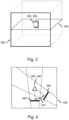
- Fig. 5 shows a result of the volume rendering, i.e., the reference view 360 showing the region of interest 380 from a first side.
- the image processing system 100 may be configured for displaying the reference view 360 when the orientation 310 of the image device 110 coincides with the reference orientation 320.
- the reference view 360 may be a default view within the image data, e.g., a default view shown at the start of the operation of the image processing system 100.
- the reference orientation 320 may coincide with an orientation of the image device 110 at the start of said operation.
- the orientation sensor may measure the change in orientation, i.e., the device rotation 330, and provide the device rotation 330 to the image processor 150 in the form of rotation data 125.
- the means 140 for establishing the center of rotation may have established the region of interest 380 as the center of rotation 340, e.g., for enabling a user to conveniently obtain views showing the region of interest 380 from various sides. It will be appreciated that, in general, establishing a region of interest as a center of rotation may comprise establishing a center of the region of interest as the center of rotation when the region of interest is a two-dimensional or three-dimensional shape in the image data 300. When the region of interest is a point, i.e., sometimes referred to as a point of interest, the center of rotation may directly coincide with the point of interest.
- the image processor 150 may establish a current view 350 in the image data 300 by firstly establishing a view rotation 370 in relation to the device rotation 330, and secondly establishing the current view 350 in dependence on the view rotation 370 around the center of rotation 340 with respect to the reference view 360.
- the establishing the view rotation 370 in relation to the device rotation 330 may comprise applying a gain to the device rotation 330 to obtain the view rotation 370.
- the device rotation 330 may be 30 degrees
- the image processor 150 may establish the view rotation 370 by multiplying the device rotation 330 with a factor of two to obtain as the view rotation a rotation of 60 degrees.
- the view rotation 370 may also equal the device rotation 330.
- FIG. 4 A result of the establishing the current view 350 in dependence on the view rotation 370 around the center of rotation 340 with respect to the reference view 360 is shown in Fig. 4 , where the current view 350 is shown to be rotated around the center of rotation 340 by an amount indicated by the view rotation 370 with respect to the reference view 360.
- Fig. 6 shows a result of the volume rendering, i.e., the current view 350 showing the region of interest 380 from a second side.
- the current view 350 shown on the display 130 shows a second side of the region of interest 380, with the second side being obtained by a rotation around the region of interest 380 with respect to the first side shown in the reference view 360 in Fig. 5 .
- a coordinate system may be defined by which the orientation 310 of the image device 110 may be expressed, i.e., a device coordinate system.
- the device coordinate system may comprise an origin, e.g., one corner of the image device 110, and three coordinate axes, e.g., an x-axis defined along a width of the image device 110, a y-axis defined along a depth of the image device 110, and a z-axis defined along a height of the image device 110.
- any other suitable coordinate system may be used as well, i.e., the choice of origin and rotation axes is not limited to the one presented above.
- the device coordinate system may be expressed in units of, e.g., millimeters.
- the reference orientation 320 e.g., an initial orientation or a previous orientation of the image device 110, may be expressed as a reference device vector in the device coordinate system.
- the reference orientation may be measured by the orientation sensor 120.
- an accelerometer or gyroscope may measure a direction of gravity for providing a reference device vector expressing the reference orientation 320 of the image device with respect to a direction or orientation of gravity.
- the orientation sensor 120 may also provide an origin of the reference device vector in the device coordinate system.
- the origin of the reference device vector may correspond to a reference position of the image device 110 with respect to the device coordinate system. It is noted, however, that the origin of the reference device vector may not be needed for establishing the reference orientation.
- the orientation sensor 120 may provide the orientation 310 of the image device 110 as a current device vector within the device coordinate system.
- the orientation sensor 120 may also provide an origin of the current device vector in the device coordinate system corresponding to a current position of the image device 110.
- the orientation sensor 120 may then compare the current device vector with the reference device vector for determining a change in orientation of the image device 110, e.g., a device rotation 330.
- the orientation sensor 120 may determine a difference between the current device vector and the reference device vector.
- the orientation sensor 120 may disregard a difference in origin of the current device vector and the reference device vector, as the difference in origin may correspond to a change in position and may not be needed for establishing a change in orientation.
- the orientation sensor 120 may also determine the change in position for providing device translation in addition to device rotation 330.
- a coordinate system may be defined by which the orientation of the views in the image data 300 may be expressed, i.e., an image coordinate system.
- the image coordinate system may define an origin as being one corner of the image data 300 as shown in Fig. 3 , i.e., corresponding to a vertex of the outline of the image data 300.
- the image coordinate system may further define three coordinate axes, e.g., running along the edges of the outline that meet at said vertex.
- the image coordinate system may be expressed in units of, e.g., millimeters.
- the image coordinate system may be related to the contents of the image data 300.
- the image coordinate system may be defined by a standard for medical image data, i.e., may be a standardized image coordinate system.
- An orientation of the reference view 360 in the image coordinate system may be expressed as a reference view vector.
- the reference view vector may be linked to the reference orientation 320 in the device coordinate system, i.e., the reference device vector.
- the link between both orientations may comprise a rotation transformation.
- the origin of the device coordinate system and the origin of the image coordinate system may not coincide.
- the origin of the reference device vector within the device coordinate system and the origin of the reference view vector in the image coordinate system may not coincide.
- an additional translation transformation may be needed for linking the reference view vector to the reference device vector.
- the rotation transformation and the possible additional translation transformation may be established when starting to operate the image processing system 100 or image device 110.
- Establishing the current view may comprise the following steps.
- the reference device vector is mapped to the reference view vector using the aforementioned rotation transformation and the possible additional translation transformation.
- the image data 300 is shifted within the image coordinate system such that the center of rotation 340 is located at the origin of the image coordinate system.
- the reference view vector is then rotated around the origin of the image coordinate system in relation to the device rotation, e.g., the difference between the current device vector and the reference device vector, thereby yielding a current view vector.
- the current view vector differs in terms of origin and in terms of direction from the reference view vector.
- the second step is reversed by shifting back the image data 300 within the image coordinate system.
- the current view vector may then be used to derive parameters for establishing the current view. For example, when the current view is established using multi-planar reformatting, i.e., slicing of volumetric data, the current view may be generated by generating an image slice through the origin of the current view vector, with a plane running along the image slice being orthogonal to the current view vector.
- multi-planar reformatting i.e., slicing of volumetric data
- Fig. 7 is similar to Fig. 5 in that it shows a result of the current view 350 being established in dependence on the reference view 360, the center of rotation 340 and the view rotation 370.
- the reference view 360 is generated by multi-planar reformatting of the image data 300, yielding as the reference view 360 a slice through the image data 300.
- the region of interest 380 is located, i.e., is visible, in the reference view 360.
- the region of interest 380 is again established as the center of rotation.
- the current view 350 is shown to be rotated around the center of rotation 340 by an amount indicated by the view rotation 370. As such, a different slice though the region of interest 380 and surrounding image data 300 is obtained.
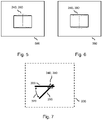
- Fig. 8 shows a graph comprising examples of functions that may be used by the image processor 150 for establishing the view rotation 370 in relation to the device rotation 320.
- the horizontal axis corresponds to the device rotation 320
- the vertical axis corresponds to the view rotation 370. Both the horizontal axis and vertical axis may show a same or similar range, e.g., from 0 to 90 degrees.
- the functions 372, 374, 376 and 378 illustrate various mappings from device rotation 320, i.e., an input of the function, to the view rotation 370, i.e., an output of the function.
- a first function 372 corresponds to a direct mapping, in which a certain amount of device rotation 320 results in a same amount of view rotation 370, e.g., 45 degrees of device rotation 320 results in 45 degrees of view rotation 370.
- a second function 374 may be used which corresponds to a gain 374.
- a certain amount of device rotation 320 results in a gained or amplified amount of view rotation 370, e.g., 22.5 degrees of device rotation 320 results in 45 degrees of view rotation 370.
- a third function 376 may be used which corresponds to a threshold 376.
- a fourth function 378 corresponds to a non-linear function 378 and may be used for obtaining, e.g., a decrease in sensitivity for small, possibly unintended device rotations 320, and an increase in sensitivity for larger device rotations 320. It will be appreciated that any other suitable function may be used as well for establishing the view rotation 370 in relation to the device rotation 320, e.g., by combining aspects of the aforementioned functions.
- Fig. 9 shows an image processing system 200 comprising the image device 110 previously shown in Fig. 1 .
- the image processing system 200 further comprises a user input 260 for receiving selection data 265 from the user, and the means 240 for establishing the center of rotation 340 is arranged for establishing the center of rotation in dependence on the selection data.
- the user may provide the selection data 265 to the user input 260 of the image processing system 200 using any suitable manner, e.g., using a keyboard 275 or a mouse 280.
- the display 130 of the image device 110 may comprise a touch-sensitive surface for enabling the user to provide the selection data 265 to the user input 260 by means of touching the display 130.
- the user may provide the selection data 265 to manually select the center of rotation 340, or to modify or influence a manner in which a region of interest detector establishes the center of rotation 340.
- the user input 260 may be arranged for receiving navigation data 270 from the user, and the image processor 250 may arranged for establishing the views 155 of the image data 300 in dependence on the navigation data.
- the user may provide the navigation data 270 to the user input 260 using any suitable manner, e.g., using the aforementioned keyboard 270, mouse 280 or display 130 equipped with a touch-sensitive surface.
- the user may use a same manner for providing the navigation data 270 as for providing the selection data 265.
- the user may also use a different manner for said providing.
- the navigation data 270 may comprise a pan and/or a zoom navigation command, with, e.g., the pan navigation command being provided by the user moving the mouse 280 and the zoom navigation command being provided by the user rotating a wheel of the mouse 280.
- the image processing system 200 may be arranged for receiving a reset command from the user for resetting the reference orientation 320 and/or the reference view 360.
- the image processing system 200 may receive the reset command in any suitable manner, e.g., using the aforementioned keyboard 270, mouse 280 or display 130 equipped with a touch-sensitive surface.
- the image processing system 200 may also be arranged for receiving a pause command for instructing the image processing system 200 to temporarily suspend establishing the views in dependence on the device rotation.
- the image processor 240 may temporarily disregard the device rotation after receiving the pause command, and may resume considering the device rotation after receiving a resume command from the user, with the resume command instructing the image processor 250 to resume establishing the views in dependence on the device rotation.
- the means 240 for establishing the center of rotation 340 may be arranged for detecting a region of interest 380 in the image data 300.
- said means 240 may comprise, function as, or be a region of interest detector.
- Said means 240 may also be arranged for establishing the center of rotation 340 in dependence on the region of interest 380.
- the region of interest detection may employ any suitable technique for detecting a region of interest.
- the region of interest detect may employ any suitable technique as are known from the field of medical image analysis for detecting medical anomalies, e.g., lesions.
- the image data may comprises volumetric image data and the image processor may be arranged for said establishing the current view by using at least one of the group of: multi-planar reformatting, volume rendering, and surface rendering, to generate the current view.
- the image data may also comprises three-dimensional graphics data and the image processor may be arranged for said establishing the current view by using graphics rendering to generate the current view. Graphics rendering is known from the field of three-dimensional computer graphics.
- the image data may comprise a combination of volumetric image data and graphics data.
- the current view may be established by using at least one of the group of: multi-planar reformatting, volume rendering, and surface rendering, in addition to using graphics rendering to generate the current view.
- Establishing the current view may comprise (i) establishing a 4x4 transformation matrix in dependence on the view rotation and the center of rotation, and (ii) generating the current view using the 4x4 transformation matrix.
- Such 4x4 transformation matrices are widely used in the field of three-dimensional computer graphics for representing projective transformations, including translation, rotation, scaling, shearing, and perspective distortion.
- the 4x4 transformation matrix may represent a combination of translation and rotation, thereby allowing the image processor to take into account a center of rotation not coinciding with an origin of the image coordinate system.
- the orientation sensor may be a so-termed accelerometer that measures the orientation by comparing an acceleration of a test mass with respect to a free-falling frame of reference. It will be appreciated that the orientation sensor may be any suitable type of accelerometer as are known from the field of accelerometers. The orientation sensor may also be a compass that measures the orientation by comparison with the Earth's magnetic field. Similarly, the orientation sensor may be a gyroscope that measures the orientation by measuring changes in the spin axis orientation of the gyroscope. The orientation sensor may also be a video camera for estimating the ego motion of the image device, i.e., the motion of the video camera and thus of the image device relative to its surroundings, by using video information acquired by the video camera.
- the orientation sensor may also comprise a combination of, e.g., accelerometer and video camera for improving the accuracy of measuring the orientation of the image device.
- the image processing system may be arranged for only considering the device rotation around a single rotation axis.
- any device rotation may only be considered with respect to said rotation axis.
- a reason for this may be to intentionally limit the user in rotating around the region of interest, or due to a limitation of the orientation sensor.
- the device rotation may also be considered around more than one rotation axis, e.g., an x-axis, y-axis and z-axis, and as such, the device rotation may be decomposed in a number of so-termed principle rotations, e.g., a so-termed yaw, pitch, and roll. A user may thus arbitrarily rotate around the region of interest in the image data.
- the image processing system may be a handheld device, i.e., incorporating the display, the orientation sensor, the means for establishing the center of rotation and the image processor.
- the handheld device may be a tablet device.
- the image processing system may also be a workstation comprising a display, with a housing of the display comprising the orientation sensor.
- the housing of the display, i.e., the image device may be physically rotatable by, e.g., being suitable mounted with respect to a desk or wall.
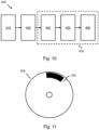
- Fig. 10 shows a method 400 of enabling a user to navigate through image data having at least three spatial dimensions by displaying views of the image data on a display of an image device, the method comprising measuring 410 an orientation of the image device with respect to a reference orientation for providing rotation data indicative of a device rotation of the image device, establishing 420 a center of rotation in the image data, and establishing 430 the views of the image data in relation to the device rotation by, for establishing a current view, (i) receiving 440 the rotation data from the orientation sensor, (ii) establishing 450 a view rotation in relation to the device rotation, and (iii) establishing 460 the current view in dependence on the view rotation around the center of rotation with respect to a reference view.
- Fig. 11 shows a computer readable medium 500 comprising a computer program 520, the computer program 520 comprising instructions for causing a processor system to perform the method 400 as shown in Fig. 10 .
- the computer program 520 may be embodied on the computer readable medium 500 as physical marks or by means of magnetization of the computer readable medium 500.
- any other suitable embodiment is conceivable as well.
- the computer readable medium 500 is shown in Fig. 11 as an optical disc, the computer readable medium 500 may be any suitable computer readable medium, such as a hard disk, solid state memory, flash memory, etc., and may be non-recordable or recordable.
- the invention also applies to computer programs, particularly computer programs on or in a carrier, adapted to put the invention into practice.
- the program may be in the form of a source code, an object code, a code intermediate source and an object code such as in a partially compiled form, or in any other form suitable for use in the implementation of the method according to the invention.
- a program may have many different architectural designs.
- a program code implementing the functionality of the method or system according to the invention may be sub-divided into one or more sub-routines. Many different ways of distributing the functionality among these sub-routines will be apparent to the skilled person.
- the sub-routines may be stored together in one executable file to form a self-contained program.
- Such an executable file may comprise computer-executable instructions, for example, processor instructions and/or interpreter instructions (e.g. Java interpreter instructions).
- one or more or all of the sub-routines may be stored in at least one external library file and linked with a main program either statically or dynamically, e.g. at run-time.
- the main program contains at least one call to at least one of the sub-routines.
- the sub-routines may also comprise function calls to each other.
- An embodiment relating to a computer program product comprises computer-executable instructions corresponding to each processing step of at least one of the methods set forth herein. These instructions may be sub-divided into sub-routines and/or stored in one or more files that may be linked statically or dynamically.
- Another embodiment relating to a computer program product comprises computer-executable instructions corresponding to each means of at least one of the systems and/or products set forth herein. These instructions may be sub-divided into sub-routines and/or stored in one or more files that may be linked statically or dynamically.
- the carrier of a computer program may be any entity or device capable of carrying the program.
- the carrier may include a storage medium, such as a ROM, for example, a CD ROM or a semiconductor ROM, or a magnetic recording medium, for example, a hard disk.
- the carrier may be a transmissible carrier such as an electric or optical signal, which may be conveyed via electric or optical cable or by radio or other means.
- the carrier may be constituted by such a cable or other device or means.
- the carrier may be an integrated circuit in which the program is embedded, the integrated circuit being adapted to perform, or used in the performance of, the relevant method.
Landscapes
- Engineering & Computer Science (AREA)
- Theoretical Computer Science (AREA)
- Physics & Mathematics (AREA)
- Computer Hardware Design (AREA)
- General Physics & Mathematics (AREA)
- General Engineering & Computer Science (AREA)
- Software Systems (AREA)
- Computer Graphics (AREA)
- Human Computer Interaction (AREA)
- Signal Processing (AREA)
- Multimedia (AREA)
- Radar, Positioning & Navigation (AREA)
- Remote Sensing (AREA)
- Geometry (AREA)
- Computing Systems (AREA)
- User Interface Of Digital Computer (AREA)
- Processing Or Creating Images (AREA)
- Image Processing (AREA)
- Image Generation (AREA)
- Computer And Data Communications (AREA)
Claims (15)
- Bildverarbeitungssystem (100, 200), um einem Benutzer zu ermöglichen, durch Bilddaten (300) mit drei räumlichen Dimensionen zu navigieren, um Ansichten (155) der Bilddaten bereitzustellen. Das Bildverarbeitungssystem umfasst:- ein Bildgebungsgerät (110) mit einem Display (130), das konfiguriert ist zum Darstellen:- von Ansichten der Bilddaten und einen Orientierungssensor (120), der dazu konfiguriert ist, eine Orientierung (310) des Bildgeräts in Bezug auf eine Referenzorientierung (320) zu messen, um Rotationsdaten (125) bereitzustellen, die eine Geräterotation (330) des Bildgeräts angeben;- ein Mittel (140, 240), konfiguriert, um ein Rotationszentrum (340) in den Bilddaten bereitzustellen; und- einen Bildprozessor (150, 250), der so konfiguriert ist, dass er die Ansichten der Bilddaten in Bezug auf die Geräterotation erstellt, indem er zum Erstellen einer aktuellen Ansicht (350) konfiguriert ist: (i) die Rotationsdaten von dem Orientierungssensor zu empfangen, (ii) eine dreidimensionale Ansichtsrotation (370) in Bezug auf die Geräterotation zu erstellen, und (iii) die aktuelle Ansicht in Abhängigkeit von der dreidimensionalen Ansichtsrotation um das Rotationszentrum in Bezug auf eine Referenzansicht (360) zu erstellen, wobei das Mittel (140, 240) zum Ermitteln des Rotationszentrums (340) einen Detektor für interessierende Bereiche umfasst, der zum automatischen Erfassen eines interessierenden Bereichs (380) in den Bilddaten (300) konfiguriert ist, und eingerichtet ist zum Bestimmen des Rotationszentrums in Abhängigkeit von dem erkannten interessierenden Bereich (380).
- Bildverarbeitungssystem (100, 200) nach Anspruch 1, wobei das Mittel (140, 240) zum Festlegen des Rotationszentrums (340) zum Festlegen des interessierenden Bereichs (380) als Rotationszentrum angeordnet ist.
- Bildverarbeitungssystem (200) nach Anspruch 1, wobei das Bildverarbeitungssystem ferner eine Benutzereingabe (260) zum Empfangen von Auswahldaten (265) von dem Benutzer umfasst und die Einrichtung (240) zum Ermitteln des Rotationszentrums eingerichtet ist zum Ermitteln des Rotationszentrums (340) in weiterer Abhängigkeit von den Auswahldaten, um es dem Benutzer zu ermöglichen, eine Art und Weise zu beeinflussen, in der das Rotationszentrum (340) eingerichtet wird.
- Bildverarbeitungssystem (200) nach Anspruch 3, wobei die Benutzereingabe (260) zum Empfangen von Navigationsdaten (270) von dem Benutzer eingerichtet ist und der Bildprozessor (250) zum Erstellen der Ansichten (155) der Bilddaten (300) in Abhängigkeit von den Navigationsdaten eingerichtet ist.
- Bildverarbeitungssystem (200) nach Anspruch 4, wobei die Navigationsdaten (270) einen Schwenk- und/oder einen Zoom-Navigationsbefehl umfassen.
- Bildverarbeitungssystem (100, 200) nach Anspruch 1, wobei die Bilddaten (300) volumetrische Bilddaten umfassen und der Bildprozessor (150, 250) eingerichtet ist zum besagten Erstellen der aktuellen Ansicht (350) unter Verwendung von mindestens einem aus der Gruppe von: Neuformatierung in mehreren Ebenen, Volumenwiedergabe und Oberflächenwiedergabe, um die aktuelle Ansicht zu erzeugen.
- Bildverarbeitungssystem (100, 200) nach Anspruch 1, wobei die Bilddaten (300) dreidimensionale Grafikdaten umfassen und der Bildprozessor (150, 250) eingerichtet ist zum besagten Erstellen der aktuellen Ansicht (350) unter Verwendung von Grafiken, um die aktuelle Ansicht zu erzeugen.
- Bildverarbeitungssystem (100, 200) nach Anspruch 1, wobei das besagte Erstellen der aktuellen Ansicht (350) (i) das Erstellen einer 4x4 Transformationsmatrix in Abhängigkeit von der Bildrotation (370) und das Zentrum der Rotation (340) sowie (ii) das Erstellen der aktuellen Ansicht unter Verwendung der 4x4 Transformationsmatrix umfasst.
- Bildverarbeitungssystem (100, 200) nach Anspruch 1, wobei der Bildprozessor (150, 250) eingerichtet ist zum Festlegen der Ansichtsrotation (370) in Bezug auf die Geräterotation (330) durch Anwenden von mindestens einem aus der Gruppe von: Direkte Zuordnung (372), Verstärkung (374), ein Offset, einen Schwellenwert (376) und eine nichtlineare Funktion (378) auf die Geräterotation, um die Ansichtsrotation zu erhalten.
- Bildverarbeitungssystem (200) nach Anspruch 1, wobei das Bildverarbeitungssystem eingerichtet ist zum Empfangen eines Rücksetzbefehls vom Benutzer zum Zurücksetzen der Referenzorientierung (320) und/oder der Referenzansicht (360).
- Bildverarbeitungssystem (200) nach Anspruch 1, wobei das Bildverarbeitungssystem eingerichtet ist zum Empfangen eines Pausenbefehls vom Benutzer, um das besagte Erstellen der Ansichten der Bilddaten in Bezug auf der Referenzansicht (330) pausieren zu lassen.
- Handgerät, welches das Bildverarbeitungssystem von Anspruch 1 enthält.
- Arbeitsplatzgerät oder Bildgebungsgerät, welches das Bildverarbeitungssystem von Anspruch 1 enthält.
- Verfahren (400), um es einem Benutzer zu ermöglichen, durch Bilddaten zu navigieren, die Folgendes aufweisen: Drei räumliche Dimensionen durch Anzeigen von Ansichten der Bilddaten auf einer Anzeige eines Bildgeräts, wobei das Verfahren Folgendes umfasst:- Messen (410) einer Ausrichtung des Bildgeräts in Bezug auf eine Bezugsausrichtung zum Bereitstellen von Rotationsdaten, die eine Rotation des Bildgeräts anzeigen;- Festlegen (420) eines Rotationszentrums in den Bilddaten; und- Erstellen (430) der Ansichten der Bilddaten in Bezug auf die Geräterotation durch, zum Erstellen einer aktuellen Ansicht, (i) Empfangen (440) der Rotationsdaten von dem Orientierungssensor, (ii) Erstellen (450) einer dreidimensionalen Bildrotation in Bezug auf die Geräterotation, und (iii) Ermitteln (460) der aktuellen Ansicht in Abhängigkeit von der dreidimensionalen Ansichtsdrehung um das Rotationszentrum in Bezug auf eine Bezugsansicht, wobei der Schritt des Ermittelns (420) des Rotationszentrums in den Bilddaten umfasst:- Eine automatische Erfassung einer Region von Interesse in den Bilddaten; und- Ermitteln des Rotationszentrums in Abhängigkeit von der erfassten Region von Interesse.
- Computerprogrammprodukt (520), das Anweisungen umfasst, um ein Prozessorsystem zu veranlassen, das Verfahren nach Anspruch 14 auszuführen.
Priority Applications (1)
| Application Number | Priority Date | Filing Date | Title |
|---|---|---|---|
| EP12715196.7A EP2695142B1 (de) | 2011-04-08 | 2012-03-30 | Bildbearbeitungssystem und -verfahren |
Applications Claiming Priority (3)
| Application Number | Priority Date | Filing Date | Title |
|---|---|---|---|
| EP11161606 | 2011-04-08 | ||
| PCT/IB2012/051536 WO2012137113A1 (en) | 2011-04-08 | 2012-03-30 | Image processing system and method. |
| EP12715196.7A EP2695142B1 (de) | 2011-04-08 | 2012-03-30 | Bildbearbeitungssystem und -verfahren |
Publications (2)
| Publication Number | Publication Date |
|---|---|
| EP2695142A1 EP2695142A1 (de) | 2014-02-12 |
| EP2695142B1 true EP2695142B1 (de) | 2023-03-01 |
Family
ID=45976457
Family Applications (1)
| Application Number | Title | Priority Date | Filing Date |
|---|---|---|---|
| EP12715196.7A Active EP2695142B1 (de) | 2011-04-08 | 2012-03-30 | Bildbearbeitungssystem und -verfahren |
Country Status (8)
| Country | Link |
|---|---|
| US (2) | US10373375B2 (de) |
| EP (1) | EP2695142B1 (de) |
| JP (1) | JP6211510B2 (de) |
| CN (2) | CN110084876A (de) |
| BR (1) | BR112013025601A2 (de) |
| MX (1) | MX2013011451A (de) |
| RU (1) | RU2612572C2 (de) |
| WO (1) | WO2012137113A1 (de) |
Families Citing this family (9)
| Publication number | Priority date | Publication date | Assignee | Title |
|---|---|---|---|---|
| US20150199105A1 (en) * | 2014-01-10 | 2015-07-16 | Silicon Graphics International, Corp. | Automatic selection of center of rotation for graphical scenes |
| FR3016998B1 (fr) * | 2014-01-29 | 2022-08-26 | Etude Et Realisation De Materiels Electroniques Speciaux Ermes | Dispositif pour visualiser des rayonnements photoniques, adapte pour travailler dans un environnement radioactif et camera utilisant un tel dispositif |
| US9189839B1 (en) * | 2014-04-24 | 2015-11-17 | Google Inc. | Automatically generating panorama tours |
| US9002647B1 (en) | 2014-06-27 | 2015-04-07 | Google Inc. | Generating turn-by-turn direction previews |
| EP3337418B1 (de) * | 2015-08-17 | 2021-10-13 | Koninklijke Philips N.V. | Brustverformungssimulation |
| WO2017091019A1 (en) | 2015-11-27 | 2017-06-01 | Samsung Electronics Co., Ltd. | Electronic device and method for displaying and generating panoramic image |
| KR102632270B1 (ko) * | 2015-11-27 | 2024-02-02 | 삼성전자주식회사 | 전자 장치 및 파노라마 영상 표시와 생성 방법 |
| WO2017149107A1 (en) * | 2016-03-03 | 2017-09-08 | Koninklijke Philips N.V. | Medical image navigation system |
| US11454511B2 (en) * | 2019-12-17 | 2022-09-27 | Chian Chiu Li | Systems and methods for presenting map and changing direction based on pointing direction |
Citations (4)
| Publication number | Priority date | Publication date | Assignee | Title |
|---|---|---|---|---|
| US7113186B2 (en) * | 2000-11-25 | 2006-09-26 | Infinitt Co., Ltd. | 3 Dimensional slab rendering system method and computer-readable medium |
| EP1884864A1 (de) * | 2006-08-02 | 2008-02-06 | Research In Motion Limited | System und Verfahren zur Anpassung der Darstellung bewegter Bilder auf einer elektronischen Vorrichtung an die Ausrichtung der Vorrichtung |
| US20090245600A1 (en) * | 2008-03-28 | 2009-10-01 | Intuitive Surgical, Inc. | Automated panning and digital zooming for robotic surgical systems |
| US20100171691A1 (en) * | 2007-01-26 | 2010-07-08 | Ralph Cook | Viewing images with tilt control on a hand-held device |
Family Cites Families (36)
| Publication number | Priority date | Publication date | Assignee | Title |
|---|---|---|---|---|
| US5557714A (en) * | 1993-01-29 | 1996-09-17 | Microsoft Corporation | Method and system for rotating a three-dimensional model about two orthogonal axes |
| JP3704652B2 (ja) | 1995-09-08 | 2005-10-12 | 株式会社日立メディコ | 3次元画像処理方法 |
| US7477768B2 (en) * | 1999-06-29 | 2009-01-13 | The Research Foundation Of State University Of New York | System and method for performing a three-dimensional virtual examination of objects, such as internal organs |
| US6697067B1 (en) | 1999-09-28 | 2004-02-24 | Cedera Software Corp. | Method and system for storing information regarding a selected view of a three dimensional image generated from a multi-frame object |
| GB2370738B (en) * | 2000-10-27 | 2005-02-16 | Canon Kk | Image processing apparatus |
| US6421413B1 (en) * | 2000-11-27 | 2002-07-16 | Ge Medical Systems Global Technology Company, Llc | Methods and apparatus for interactively displaying curved reformation images |
| JP2002351309A (ja) * | 2001-05-30 | 2002-12-06 | Cad Center:Kk | 都市vr地図連動情報表示装置 |
| US20050169507A1 (en) * | 2001-11-21 | 2005-08-04 | Kevin Kreeger | Registration of scanning data acquired from different patient positions |
| JP2003319157A (ja) * | 2002-04-18 | 2003-11-07 | Canon Inc | 画像処理装置、画像回転方法、プログラムおよび記憶媒体 |
| CN100388317C (zh) * | 2002-06-28 | 2008-05-14 | 富士通株式会社 | 三维图象的比较程序、比较方法及比较装置 |
| JP2005107972A (ja) * | 2003-09-30 | 2005-04-21 | Canon Inc | 複合現実感提示方法、複合現実感提示装置 |
| JP2007531554A (ja) * | 2003-11-03 | 2007-11-08 | ブラッコ イメージング エス.ピー.エー. | 管状構造を立体的に表示するディスプレイ及び該ディスプレイのための改善された技術(「ステレオ・ディスプレイ」) |
| JP2006019950A (ja) * | 2004-06-30 | 2006-01-19 | Toshiba Corp | 映像信号処理装置及び映像信号処理方法 |
| JP4644449B2 (ja) * | 2004-07-12 | 2011-03-02 | 富士通株式会社 | 画像表示装置および画像表示プログラム |
| US20090156935A1 (en) | 2004-10-08 | 2009-06-18 | Koninklijke Philips Electronics N.V. | Three Dimensional Diagnostic Ultrasound Imaging System with Image Reversal and Inversion |
| JP2006146440A (ja) | 2004-11-17 | 2006-06-08 | Sony Corp | 電子機器及び情報表示選択方法 |
| US8744146B2 (en) * | 2004-12-06 | 2014-06-03 | Siemens Aktiengellschaft | Vascular reformatting using curved planar reformation |
| KR100677569B1 (ko) * | 2004-12-13 | 2007-02-02 | 삼성전자주식회사 | 입체영상장치 |
| DE102005036998B4 (de) * | 2005-08-05 | 2014-11-20 | Siemens Aktiengesellschaft | Vorrichtung zur automatischen Detektion von Auffälligkeiten in medizinischen Bilddaten |
| US20070206030A1 (en) * | 2006-03-06 | 2007-09-06 | The Protomold Company, Inc. | Graphical user interface for three-dimensional manipulation of a part |
| WO2007138604A2 (en) * | 2006-06-01 | 2007-12-06 | Ben-Gurion University Of The Negev Research And Development Authority | Denitrification treatment system and method |
| US20070279435A1 (en) | 2006-06-02 | 2007-12-06 | Hern Ng | Method and system for selective visualization and interaction with 3D image data |
| EP1884863A1 (de) * | 2006-08-02 | 2008-02-06 | Research In Motion Limited | System und Verfahren zur Anpassung der Text- und Bilddarstellung für ein elektronisches Gerät je nach der Orientierung des Geräts |
| US8248413B2 (en) * | 2006-09-18 | 2012-08-21 | Stryker Corporation | Visual navigation system for endoscopic surgery |
| RU2372844C1 (ru) | 2008-06-16 | 2009-11-20 | Общество с ограниченной ответственностью (ООО) "Кардиовид" | Способ автоматического определения размеров и положения сердца пациента по флюорографическим снимкам |
| JP2010026064A (ja) | 2008-07-16 | 2010-02-04 | Sony Computer Entertainment Inc | 携帯型画像表示装置、その制御方法、プログラム及び情報記憶媒体 |
| US20100053151A1 (en) | 2008-09-02 | 2010-03-04 | Samsung Electronics Co., Ltd | In-line mediation for manipulating three-dimensional content on a display device |
| US8788977B2 (en) * | 2008-11-20 | 2014-07-22 | Amazon Technologies, Inc. | Movement recognition as input mechanism |
| WO2010060211A1 (en) * | 2008-11-28 | 2010-06-03 | Nortel Networks Limited | Method and apparatus for controling a camera view into a three dimensional computer-generated virtual environment |
| US8441441B2 (en) | 2009-01-06 | 2013-05-14 | Qualcomm Incorporated | User interface for mobile devices |
| US8294766B2 (en) * | 2009-01-28 | 2012-10-23 | Apple Inc. | Generating a three-dimensional model using a portable electronic device recording |
| US20110024898A1 (en) * | 2009-07-31 | 2011-02-03 | Ati Technologies Ulc | Method of manufacturing substrates having asymmetric buildup layers |
| US10198854B2 (en) * | 2009-08-14 | 2019-02-05 | Microsoft Technology Licensing, Llc | Manipulation of 3-dimensional graphical objects for view in a multi-touch display |
| DE112010004349T5 (de) * | 2009-11-11 | 2012-12-13 | Activiews Ltd. | Systeme & Verfahren zum Planen und Durchführen perkutaner Nadelverfahren |
| US8543917B2 (en) * | 2009-12-11 | 2013-09-24 | Nokia Corporation | Method and apparatus for presenting a first-person world view of content |
| US8581905B2 (en) * | 2010-04-08 | 2013-11-12 | Disney Enterprises, Inc. | Interactive three dimensional displays on handheld devices |
-
2012
- 2012-03-30 BR BR112013025601A patent/BR112013025601A2/pt not_active Application Discontinuation
- 2012-03-30 CN CN201910021814.6A patent/CN110084876A/zh active Pending
- 2012-03-30 CN CN201280017220.4A patent/CN103493103A/zh active Pending
- 2012-03-30 MX MX2013011451A patent/MX2013011451A/es active IP Right Grant
- 2012-03-30 EP EP12715196.7A patent/EP2695142B1/de active Active
- 2012-03-30 US US14/007,698 patent/US10373375B2/en active Active
- 2012-03-30 RU RU2013149804A patent/RU2612572C2/ru active
- 2012-03-30 WO PCT/IB2012/051536 patent/WO2012137113A1/en active Application Filing
- 2012-03-30 JP JP2014503246A patent/JP6211510B2/ja active Active
-
2019
- 2019-08-02 US US16/530,661 patent/US10629002B2/en active Active
Patent Citations (4)
| Publication number | Priority date | Publication date | Assignee | Title |
|---|---|---|---|---|
| US7113186B2 (en) * | 2000-11-25 | 2006-09-26 | Infinitt Co., Ltd. | 3 Dimensional slab rendering system method and computer-readable medium |
| EP1884864A1 (de) * | 2006-08-02 | 2008-02-06 | Research In Motion Limited | System und Verfahren zur Anpassung der Darstellung bewegter Bilder auf einer elektronischen Vorrichtung an die Ausrichtung der Vorrichtung |
| US20100171691A1 (en) * | 2007-01-26 | 2010-07-08 | Ralph Cook | Viewing images with tilt control on a hand-held device |
| US20090245600A1 (en) * | 2008-03-28 | 2009-10-01 | Intuitive Surgical, Inc. | Automated panning and digital zooming for robotic surgical systems |
Also Published As
| Publication number | Publication date |
|---|---|
| CN103493103A (zh) | 2014-01-01 |
| JP2014512607A (ja) | 2014-05-22 |
| US10373375B2 (en) | 2019-08-06 |
| EP2695142A1 (de) | 2014-02-12 |
| RU2013149804A (ru) | 2015-05-20 |
| WO2012137113A1 (en) | 2012-10-11 |
| US10629002B2 (en) | 2020-04-21 |
| BR112013025601A2 (pt) | 2016-12-27 |
| CN110084876A (zh) | 2019-08-02 |
| MX2013011451A (es) | 2013-10-17 |
| JP6211510B2 (ja) | 2017-10-11 |
| US20190371063A1 (en) | 2019-12-05 |
| US20140022242A1 (en) | 2014-01-23 |
| RU2612572C2 (ru) | 2017-03-09 |
Similar Documents
| Publication | Publication Date | Title |
|---|---|---|
| US10629002B2 (en) | Measurements and calibration utilizing colorimetric sensors | |
| US11010965B2 (en) | Virtual object placement for augmented reality | |
| CN104995666B (zh) | 用于在真实环境中表示虚拟信息的方法 | |
| US9224237B2 (en) | Simulating three-dimensional views using planes of content | |
| US9591295B2 (en) | Approaches for simulating three-dimensional views | |
| US11087471B2 (en) | 2D obstacle boundary detection | |
| KR101650269B1 (ko) | 화면 제어를 위한 효율적인 인터페이스를 제공하는 시스템 및 방법 | |
| US11562545B2 (en) | Method and device for providing augmented reality, and computer program | |
| EP3275182B1 (de) | Verfahren und systeme für durch lichtfeld erweiterte realität/virtuelle realität auf mobilen vorrichtungen | |
| JP2009157591A (ja) | 3次元データ処理装置、3次元画像生成装置、ナビゲーション装置及び3次元データ処理プログラム | |
| US20040135974A1 (en) | System and architecture for displaying three dimensional data | |
| CN114972689A (zh) | 执行增强现实姿态确定的方法和装置 | |
| EP2624117A2 (de) | System und Verfahren zum Bereitstellen eines sichtbaren dreidimensionalen Anzeigecursors | |
| Trapp et al. | Strategies for visualizing points-of-interest of 3D virtual environments on mobile devices | |
| Korneva | Low-cost Stereoscopic Solution for Operations in the Prospective Science Space Missions |
Legal Events
| Date | Code | Title | Description |
|---|---|---|---|
| PUAI | Public reference made under article 153(3) epc to a published international application that has entered the european phase |
Free format text: ORIGINAL CODE: 0009012 |
|
| 17P | Request for examination filed |
Effective date: 20131108 |
|
| AK | Designated contracting states |
Kind code of ref document: A1 Designated state(s): AL AT BE BG CH CY CZ DE DK EE ES FI FR GB GR HR HU IE IS IT LI LT LU LV MC MK MT NL NO PL PT RO RS SE SI SK SM TR |
|
| DAX | Request for extension of the european patent (deleted) | ||
| STAA | Information on the status of an ep patent application or granted ep patent |
Free format text: STATUS: EXAMINATION IS IN PROGRESS |
|
| 17Q | First examination report despatched |
Effective date: 20190222 |
|
| STAA | Information on the status of an ep patent application or granted ep patent |
Free format text: STATUS: EXAMINATION IS IN PROGRESS |
|
| RAP1 | Party data changed (applicant data changed or rights of an application transferred) |
Owner name: KONINKLIJKE PHILIPS N.V. Owner name: PHILIPS INTELLECTUAL PROPERTY & STANDARDS GMBH |
|
| STAA | Information on the status of an ep patent application or granted ep patent |
Free format text: STATUS: EXAMINATION IS IN PROGRESS |
|
| REG | Reference to a national code |
Ref country code: DE Ref legal event code: R079 Ref document number: 602012079320 Country of ref document: DE Free format text: PREVIOUS MAIN CLASS: G06T0015200000 Ipc: H04N0013349000 |
|
| GRAP | Despatch of communication of intention to grant a patent |
Free format text: ORIGINAL CODE: EPIDOSNIGR1 |
|
| STAA | Information on the status of an ep patent application or granted ep patent |
Free format text: STATUS: GRANT OF PATENT IS INTENDED |
|
| RIC1 | Information provided on ipc code assigned before grant |
Ipc: G06T 15/20 20110101ALI20220909BHEP Ipc: G06T 19/00 20110101ALI20220909BHEP Ipc: G06F 3/04815 20220101ALI20220909BHEP Ipc: G06F 1/16 20060101ALI20220909BHEP Ipc: H04N 13/398 20180101ALI20220909BHEP Ipc: H04N 13/349 20180101AFI20220909BHEP |
|
| INTG | Intention to grant announced |
Effective date: 20221010 |
|
| GRAS | Grant fee paid |
Free format text: ORIGINAL CODE: EPIDOSNIGR3 |
|
| GRAA | (expected) grant |
Free format text: ORIGINAL CODE: 0009210 |
|
| STAA | Information on the status of an ep patent application or granted ep patent |
Free format text: STATUS: THE PATENT HAS BEEN GRANTED |
|
| AK | Designated contracting states |
Kind code of ref document: B1 Designated state(s): AL AT BE BG CH CY CZ DE DK EE ES FI FR GB GR HR HU IE IS IT LI LT LU LV MC MK MT NL NO PL PT RO RS SE SI SK SM TR |
|
| REG | Reference to a national code |
Ref country code: GB Ref legal event code: FG4D |
|
| REG | Reference to a national code |
Ref country code: CH Ref legal event code: EP Ref country code: AT Ref legal event code: REF Ref document number: 1551835 Country of ref document: AT Kind code of ref document: T Effective date: 20230315 |
|
| REG | Reference to a national code |
Ref country code: DE Ref legal event code: R096 Ref document number: 602012079320 Country of ref document: DE |
|
| REG | Reference to a national code |
Ref country code: IE Ref legal event code: FG4D |
|
| REG | Reference to a national code |
Ref country code: DE Ref legal event code: R084 Ref document number: 602012079320 Country of ref document: DE |
|
| REG | Reference to a national code |
Ref country code: GB Ref legal event code: 746 Effective date: 20230510 |
|
| REG | Reference to a national code |
Ref country code: LT Ref legal event code: MG9D |
|
| REG | Reference to a national code |
Ref country code: NL Ref legal event code: MP Effective date: 20230301 |
|
| PG25 | Lapsed in a contracting state [announced via postgrant information from national office to epo] |
Ref country code: RS Free format text: LAPSE BECAUSE OF FAILURE TO SUBMIT A TRANSLATION OF THE DESCRIPTION OR TO PAY THE FEE WITHIN THE PRESCRIBED TIME-LIMIT Effective date: 20230301 Ref country code: NO Free format text: LAPSE BECAUSE OF FAILURE TO SUBMIT A TRANSLATION OF THE DESCRIPTION OR TO PAY THE FEE WITHIN THE PRESCRIBED TIME-LIMIT Effective date: 20230601 Ref country code: LV Free format text: LAPSE BECAUSE OF FAILURE TO SUBMIT A TRANSLATION OF THE DESCRIPTION OR TO PAY THE FEE WITHIN THE PRESCRIBED TIME-LIMIT Effective date: 20230301 Ref country code: LT Free format text: LAPSE BECAUSE OF FAILURE TO SUBMIT A TRANSLATION OF THE DESCRIPTION OR TO PAY THE FEE WITHIN THE PRESCRIBED TIME-LIMIT Effective date: 20230301 Ref country code: HR Free format text: LAPSE BECAUSE OF FAILURE TO SUBMIT A TRANSLATION OF THE DESCRIPTION OR TO PAY THE FEE WITHIN THE PRESCRIBED TIME-LIMIT Effective date: 20230301 Ref country code: ES Free format text: LAPSE BECAUSE OF FAILURE TO SUBMIT A TRANSLATION OF THE DESCRIPTION OR TO PAY THE FEE WITHIN THE PRESCRIBED TIME-LIMIT Effective date: 20230301 |
|
| REG | Reference to a national code |
Ref country code: AT Ref legal event code: MK05 Ref document number: 1551835 Country of ref document: AT Kind code of ref document: T Effective date: 20230301 |
|
| PG25 | Lapsed in a contracting state [announced via postgrant information from national office to epo] |
Ref country code: SE Free format text: LAPSE BECAUSE OF FAILURE TO SUBMIT A TRANSLATION OF THE DESCRIPTION OR TO PAY THE FEE WITHIN THE PRESCRIBED TIME-LIMIT Effective date: 20230301 Ref country code: PL Free format text: LAPSE BECAUSE OF FAILURE TO SUBMIT A TRANSLATION OF THE DESCRIPTION OR TO PAY THE FEE WITHIN THE PRESCRIBED TIME-LIMIT Effective date: 20230301 Ref country code: NL Free format text: LAPSE BECAUSE OF FAILURE TO SUBMIT A TRANSLATION OF THE DESCRIPTION OR TO PAY THE FEE WITHIN THE PRESCRIBED TIME-LIMIT Effective date: 20230301 Ref country code: GR Free format text: LAPSE BECAUSE OF FAILURE TO SUBMIT A TRANSLATION OF THE DESCRIPTION OR TO PAY THE FEE WITHIN THE PRESCRIBED TIME-LIMIT Effective date: 20230602 Ref country code: FI Free format text: LAPSE BECAUSE OF FAILURE TO SUBMIT A TRANSLATION OF THE DESCRIPTION OR TO PAY THE FEE WITHIN THE PRESCRIBED TIME-LIMIT Effective date: 20230301 |
|
| PG25 | Lapsed in a contracting state [announced via postgrant information from national office to epo] |
Ref country code: SM Free format text: LAPSE BECAUSE OF FAILURE TO SUBMIT A TRANSLATION OF THE DESCRIPTION OR TO PAY THE FEE WITHIN THE PRESCRIBED TIME-LIMIT Effective date: 20230301 Ref country code: RO Free format text: LAPSE BECAUSE OF FAILURE TO SUBMIT A TRANSLATION OF THE DESCRIPTION OR TO PAY THE FEE WITHIN THE PRESCRIBED TIME-LIMIT Effective date: 20230301 Ref country code: PT Free format text: LAPSE BECAUSE OF FAILURE TO SUBMIT A TRANSLATION OF THE DESCRIPTION OR TO PAY THE FEE WITHIN THE PRESCRIBED TIME-LIMIT Effective date: 20230703 Ref country code: EE Free format text: LAPSE BECAUSE OF FAILURE TO SUBMIT A TRANSLATION OF THE DESCRIPTION OR TO PAY THE FEE WITHIN THE PRESCRIBED TIME-LIMIT Effective date: 20230301 Ref country code: CZ Free format text: LAPSE BECAUSE OF FAILURE TO SUBMIT A TRANSLATION OF THE DESCRIPTION OR TO PAY THE FEE WITHIN THE PRESCRIBED TIME-LIMIT Effective date: 20230301 Ref country code: AT Free format text: LAPSE BECAUSE OF FAILURE TO SUBMIT A TRANSLATION OF THE DESCRIPTION OR TO PAY THE FEE WITHIN THE PRESCRIBED TIME-LIMIT Effective date: 20230301 |
|
| REG | Reference to a national code |
Ref country code: CH Ref legal event code: PL |
|
| PG25 | Lapsed in a contracting state [announced via postgrant information from national office to epo] |
Ref country code: SK Free format text: LAPSE BECAUSE OF FAILURE TO SUBMIT A TRANSLATION OF THE DESCRIPTION OR TO PAY THE FEE WITHIN THE PRESCRIBED TIME-LIMIT Effective date: 20230301 Ref country code: IS Free format text: LAPSE BECAUSE OF FAILURE TO SUBMIT A TRANSLATION OF THE DESCRIPTION OR TO PAY THE FEE WITHIN THE PRESCRIBED TIME-LIMIT Effective date: 20230701 |
|
| REG | Reference to a national code |
Ref country code: BE Ref legal event code: MM Effective date: 20230331 |
|
| REG | Reference to a national code |
Ref country code: DE Ref legal event code: R097 Ref document number: 602012079320 Country of ref document: DE |
|
| PG25 | Lapsed in a contracting state [announced via postgrant information from national office to epo] |
Ref country code: LU Free format text: LAPSE BECAUSE OF NON-PAYMENT OF DUE FEES Effective date: 20230330 |
|
| PLBE | No opposition filed within time limit |
Free format text: ORIGINAL CODE: 0009261 |
|
| STAA | Information on the status of an ep patent application or granted ep patent |
Free format text: STATUS: NO OPPOSITION FILED WITHIN TIME LIMIT |
|
| PG25 | Lapsed in a contracting state [announced via postgrant information from national office to epo] |
Ref country code: MC Free format text: LAPSE BECAUSE OF FAILURE TO SUBMIT A TRANSLATION OF THE DESCRIPTION OR TO PAY THE FEE WITHIN THE PRESCRIBED TIME-LIMIT Effective date: 20230301 |
|
| REG | Reference to a national code |
Ref country code: IE Ref legal event code: MM4A |
|
| PG25 | Lapsed in a contracting state [announced via postgrant information from national office to epo] |
Ref country code: SI Free format text: LAPSE BECAUSE OF FAILURE TO SUBMIT A TRANSLATION OF THE DESCRIPTION OR TO PAY THE FEE WITHIN THE PRESCRIBED TIME-LIMIT Effective date: 20230301 Ref country code: MC Free format text: LAPSE BECAUSE OF FAILURE TO SUBMIT A TRANSLATION OF THE DESCRIPTION OR TO PAY THE FEE WITHIN THE PRESCRIBED TIME-LIMIT Effective date: 20230301 Ref country code: LI Free format text: LAPSE BECAUSE OF NON-PAYMENT OF DUE FEES Effective date: 20230331 Ref country code: IE Free format text: LAPSE BECAUSE OF NON-PAYMENT OF DUE FEES Effective date: 20230330 Ref country code: FR Free format text: LAPSE BECAUSE OF NON-PAYMENT OF DUE FEES Effective date: 20230501 Ref country code: DK Free format text: LAPSE BECAUSE OF FAILURE TO SUBMIT A TRANSLATION OF THE DESCRIPTION OR TO PAY THE FEE WITHIN THE PRESCRIBED TIME-LIMIT Effective date: 20230301 Ref country code: CH Free format text: LAPSE BECAUSE OF NON-PAYMENT OF DUE FEES Effective date: 20230331 |
|
| 26N | No opposition filed |
Effective date: 20231204 |
|
| PG25 | Lapsed in a contracting state [announced via postgrant information from national office to epo] |
Ref country code: BE Free format text: LAPSE BECAUSE OF NON-PAYMENT OF DUE FEES Effective date: 20230331 |
|
| PGFP | Annual fee paid to national office [announced via postgrant information from national office to epo] |
Ref country code: DE Payment date: 20240328 Year of fee payment: 13 Ref country code: GB Payment date: 20240319 Year of fee payment: 13 |