EP2695013B1 - Schieber zum einschieben in den beobachtungsstrahlengang eines mikroskops - Google Patents
Schieber zum einschieben in den beobachtungsstrahlengang eines mikroskops Download PDFInfo
- Publication number
- EP2695013B1 EP2695013B1 EP12707074.6A EP12707074A EP2695013B1 EP 2695013 B1 EP2695013 B1 EP 2695013B1 EP 12707074 A EP12707074 A EP 12707074A EP 2695013 B1 EP2695013 B1 EP 2695013B1
- Authority
- EP
- European Patent Office
- Prior art keywords
- holder
- slider
- stack
- optical elements
- polarizer
- Prior art date
- Legal status (The legal status is an assumption and is not a legal conclusion. Google has not performed a legal analysis and makes no representation as to the accuracy of the status listed.)
- Not-in-force
Links
- 230000003287 optical effect Effects 0.000 claims description 55
- 238000000034 method Methods 0.000 claims description 52
- 238000010008 shearing Methods 0.000 claims description 19
- 230000010287 polarization Effects 0.000 claims description 13
- 238000003780 insertion Methods 0.000 claims description 8
- 230000037431 insertion Effects 0.000 claims description 8
- 239000004372 Polyvinyl alcohol Substances 0.000 claims description 5
- 229920002451 polyvinyl alcohol Polymers 0.000 claims description 5
- 238000006073 displacement reaction Methods 0.000 claims description 2
- 230000005540 biological transmission Effects 0.000 description 9
- 238000005286 illumination Methods 0.000 description 9
- 239000000463 material Substances 0.000 description 5
- 239000006059 cover glass Substances 0.000 description 3
- 238000013461 design Methods 0.000 description 3
- 238000010276 construction Methods 0.000 description 2
- 238000003384 imaging method Methods 0.000 description 2
- 210000001747 pupil Anatomy 0.000 description 2
- 230000001427 coherent effect Effects 0.000 description 1
- 238000011161 development Methods 0.000 description 1
- 239000000975 dye Substances 0.000 description 1
- 230000005284 excitation Effects 0.000 description 1
- 239000007850 fluorescent dye Substances 0.000 description 1
- 239000011521 glass Substances 0.000 description 1
- 238000004519 manufacturing process Methods 0.000 description 1
- 239000002184 metal Substances 0.000 description 1
- 239000002923 metal particle Substances 0.000 description 1
- 238000012986 modification Methods 0.000 description 1
- 230000004048 modification Effects 0.000 description 1
- 210000001331 nose Anatomy 0.000 description 1
- 230000008447 perception Effects 0.000 description 1
- 229920003023 plastic Polymers 0.000 description 1
- 229920000642 polymer Polymers 0.000 description 1
- 230000001179 pupillary effect Effects 0.000 description 1
- 238000000926 separation method Methods 0.000 description 1
Images

Classifications
-
- G—PHYSICS
- G02—OPTICS
- G02B—OPTICAL ELEMENTS, SYSTEMS OR APPARATUS
- G02B21/00—Microscopes
- G02B21/0004—Microscopes specially adapted for specific applications
- G02B21/0092—Polarisation microscopes
-
- G—PHYSICS
- G02—OPTICS
- G02B—OPTICAL ELEMENTS, SYSTEMS OR APPARATUS
- G02B7/00—Mountings, adjusting means, or light-tight connections, for optical elements
- G02B7/006—Filter holders
-
- G—PHYSICS
- G02—OPTICS
- G02B—OPTICAL ELEMENTS, SYSTEMS OR APPARATUS
- G02B21/00—Microscopes
- G02B21/06—Means for illuminating specimens
- G02B21/08—Condensers
- G02B21/14—Condensers affording illumination for phase-contrast observation
-
- G—PHYSICS
- G02—OPTICS
- G02B—OPTICAL ELEMENTS, SYSTEMS OR APPARATUS
- G02B21/00—Microscopes
- G02B21/34—Microscope slides, e.g. mounting specimens on microscope slides
Definitions
- the invention relates to a slide for insertion into the observation beam path of a microscope.
- a slide comprises a first holder in which a stack of optical elements for a first observation method, namely a polarization-optical, differential interference contrast method, is arranged.
- the stack of optical elements comprises a polarizer and optical polarization shearing elements, for example in the form of a Wollaston prism or modified Wollaston prism composed of several individual prisms, in particular in the form of a Nomarski prism.
- Objects to be examined microscopically can essentially be divided into two classes, namely into amplitude objects and phase objects.
- amplitude objects change the light, which is used to illuminate them, in its brightness or intensity, or also in the wavelength, for example when dyes are excited to emit.
- amplitude objects can be made directly visible.
- Phase objects on the other hand, only change the phase position of the light, for example due to deviations in the refractive index or the thickness relative to the environment, so that direct perception is not possible even with electronic image sensors.
- phase objects can also be marked with fluorescent markers so that they are made directly visible in this way.
- phase contrast and interference contrast methods In order to make unmarked phase objects visible, various microscopic methods have been developed, namely phase contrast and interference contrast methods.
- DIC differential interference contrast method
- Nomarski prism which is a modification of a Wollaston prism
- a polarizer for generating linearly polarized light is introduced into the beam path in front of the first Nomarski prism.
- the light is analyzed with the aid of a second polarizer, the analyzer. Due to the lighting-side Nomarski prism, the light is split into two coherent partial waves independently of the object, both of which are influenced by the object.
- the partial beams are brought together by the second prism and can interfere with one another behind the analyzer.
- the transmission directions of the polarizer and analyzer are perpendicular to each other.
- the disadvantage of this design is that both the objective and all optical elements in the illumination beam path must be isotropic in terms of polarization, so that birefringent plastic slides or objectives with noticeable stress birefringence cannot be used.
- PlasDIC process A further development of this process is the so-called PlasDIC process, which is used, for example, in the EP 1 359 453 B1 and in an article by R. Danz et al. in the magazine "Photonik", issue 1/2004 on pages 42-45 is described. Express reference is made to both documents with regard to the description of the PlasDIC process.
- the linearly polarized light is only generated immediately in front of the imaging-side Nomarski prism, a slit diaphragm being used instead of a prism on the illumination side.
- the width of the slit should be selected so that the effective pupillary path difference in the direction of the slit width is less than or equal to a quarter wavelength or a quarter of the interference fringe spacing in the pupil.
- This type of sample contrasting in imaging is often combined with other types of contrasting, for example with fluorescence contrasting.
- polarizer and analyzer must be removed from the beam path so as not to weaken the fluorescence falling on the detector.
- the components that act interferometrically for example the Wollaston or Nomarski prism, must also be removed from the beam path.
- a lens change may also be necessary.
- special excitation and emission filters must be placed in the beam path.
- the essential components for the PlasDIC process are polarizer, shearing elements and analyzer.
- the analyzer is usually arranged in a filter turret or filter slide, which also contains the fluorescence emission filter and when changing the observation method swaps the active place in the observation beam path with them.
- the polarizer and shearing elements are cemented together and are offered as a so-called PlasDIC prism for a range of lenses.
- the common PlasDIC prisms are inserted in the observation beam path directly behind the lens in the beam path.
- the revolvers have a receptacle which enables the prisms to be inserted into the objective nosepiece directly below the objective contact surface. They then move in the nosepiece with the assigned objective.
- the PlasDIC prisms are usually arranged in special slides, as they are, for example, also in the above-mentioned article by R. Danz et al. are described.
- a PlasDIC prism can also be used for several objectives.
- the PlasDIC prism can also be positioned in a plane outside of the nosepiece so that it is not moved along with it as soon as the objective is changed.
- the filter turret, objective turret and / or the focus drive are operated by a motor and moved automatically via a PC connection and corresponding programs.
- the PlasDIC prism - or in the case of the DIC method the normaskiprism on the image side - must, however, also be removed manually if the microscope is partially motorized.
- the cemented polarizer leads to a reduced transmission of about 25% when using a polymer-based polarizer. If this polarizer is not removed, operators could attribute the observed reduced fluorescence intensity to a general weakness of the microscope.
- the object of the invention is therefore to further develop a slide of the type described above that is suitable for performing the PlasDIC method, as well as a corresponding microscope, so that the number of steps required to switch between the various observation methods in manual or partially motorized microscopes is reduced becomes.
- the number of components to be moved should also be reduced, as well as the possibility of incorrect operation by the user.
- the stack of optical elements in the first holder comprises an analyzer which is arranged in the stack with respect to its polarization direction in a fixed predetermined orientation with respect to the polarization direction of the polarizer, the stack Optical elements is arranged exchangeably in the first holder and the slide comprises at least one further holder for receiving optical elements for at least one further observation method.
- the orientation of the shearing elements remains the same relative to the polarization directions and thus to the transmission directions of the two polarizing elements.
- the condenser-side slit diaphragm which fulfills the ⁇ / 4 condition, has to be introduced into the beam path, which is, for example, when changing between fluorescent incident light illumination on the one hand and PlasDIC transmitted light illumination, on the other hand, does not require any action due to the change in the direction of illumination.
- the transmission directions of the polarizer and analyzer can be set to one another as desired, but they are preferably crossed to one another at an angle of 90 ° and together at 45 ° to the direction of splitting of the Nomarski prism. This orientation ensures the maximum contrast.
- the fixed orientation of the transmission directions and the splitting direction to one another also makes it possible to determine the direction in which the slide is inserted into the microscope, and thus the position of a corresponding slide mount in the microscope can be chosen more flexibly and in principle at will, which increases the scope with regard to the construction.
- the contrast can be varied by influencing the path difference, in which the prism is decentered perpendicular to the optical axis. In the case of microscopes, as can be found in the prior art, this was previously not possible due to the separation of the analyzer on the one hand and the polarizer and prism on the other.
- the stack of optical elements is arranged interchangeably in the first holder, which on the one hand makes it possible to insert PlasDIC stacks for different lens groups in the slide, but on the other hand also creates the possibility of inserting the PlasDIC stacks at different angles into the slide with corresponding mounts.
- the slide comprises at least one further holder for receiving optical elements for at least one further observation method.
- a filter for the fluorescence emission for example, can be placed in a second holder; the holder can also remain free in order to enable bright-field illumination with a clear passage.
- the further observation method can also be a customary DIC method, for example according to Smith / Normaski, or a PlasDIC method that works with other parameters, for example other shearing elements, other polarizers / analyzers, with the The difference can also simply lie in a different position of the transmission directions of the polarizer and analyzer, or in a different tilt angle with respect to the optical axis.
- Variations of the PlasDIC method are also subsumed under the term "further observation method".
- Optical elements for a third observation method can then be arranged in the third holder, for example a polarizer for transmitted light observation with polarization contrast.
- the slide according to the invention By means of the slide according to the invention, switching between two different contrasting methods, in particular between a PlasDIC method and a fluorescence contrast method or other contrast methods that do not require polarization, is made easier for the operator by turning off both the shearing elements and both polarization-optical elements with one hand movement removed from the beam path. The user cannot inadvertently forget to remove the analyzer and / or the PlasDIC slide from the beam path as well, since this is removed at the same time as the other elements.
- the stack of optical elements can also easily be exchanged for a different stack that is optimized for a different group of lenses, for example.
- the optical elements of the stack are preferably cemented to one another. On the one hand, this enables the stack to be easily exchanged for another and, on the other hand, also ensures that the optical effect and the position of the transmission directions of the analyzer and polarizer are permanently fixed, since the individual elements cannot be shifted relative to one another. On the other hand, it is also possible to grasp the optical elements individually or in groups and then to insert the optical elements in their mounts into a correspondingly configured slide. This enables, for example, the replacement of the shearing elements independently of the polarizer and analyzer or the use of other polarizers and analyzers with the same shearing elements.
- the shearing elements can include, for example, two wedge prisms which are cemented to one another and preferably form a Nomarski prism or Wollaston prism. However, more than two prisms can also be used.
- the polarizer and analyzer preferably each consist of a polyvinyl alcohol film (PVA film). It is also possible to use polarizers and analyzers made of other materials, such as, for example, based on glasses interspersed with metal particles or polarizers based on metal strip grids , so-called wire-grid polarizers.
- PVA film polyvinyl alcohol film
- the polar, ie polarizer and analyzer consist of PVA film
- they are preferably cemented in each case on the side facing away from the shearing elements with a cover glass, which protects the polar from damage. If other materials are used, such a cover glass may also be dispensed with. With their side facing the shearing elements, the polar can also be cemented to this.
- the first holder into which the stack of optical elements is inserted is preferably designed as a slide-in holder for an insert.
- the optical elements of the stack - in the case of cemented elements, the stack itself - are held in this slot; it serves as a mount.
- the insert can then be pushed into the insert holder, usually along the longitudinal axis of the slide, which corresponds to the pushing direction of the slide used in the microscope.
- the stack of optical elements is combined to form an insert to be inserted into the insert holder.
- inserts it is possible, for example, to implement different tilts of the stack of optical elements so that the Contrasting direction can be varied.
- the stack of optical elements is simply inserted into a different insert with which a different tilt is implemented, or the insert is exchanged for another if the optical elements are glued to the insert, for example are firmly connected.
- the insert is expediently equipped with a knurled screw for the lateral displacement of the stack of optical elements in the insert. This means that the path difference can be varied independently of the sample.
- the slide-in unit itself can be fixed in the slide with a force fit or a form fit, for example by means of magnetic holders or screws.
- the invention also relates to a microscope with a slide according to the invention, as described above.
- a microscope includes, among other things, an objective turret with several objectives and a slide mount.
- the slide mount is rigidly arranged in the observation beam path between the objective nosepiece and an eyepiece tube.
- corresponding slides with stacks of optical elements for the PlasDIC process had to be used in the objective nosepiece itself, but the inventive positioning of the slide mount is independent of the objective nosepiece and also independent of a filter turret or filter slider, so that a stack of optical elements for the PlasDIC process also can be used for multiple lenses.
- a simultaneous recording of a fluorescence contrast image and a PlasDIC image is basically possible during observation, since the corresponding filter position in the filter turret or filter slide is not blocked by the analyzer.
- a slide 1 for insertion into the observation beam path of a microscope is shown in a plan view.
- This slide comprises a first holder 2.
- a stack of optical elements for a first observation method, the PlasDIC method, is arranged in the first holder 2.
- the stack of optical elements in the first holder 2 comprises a polarizer, polarization-optical shearing elements and an analyzer.
- the analyzer is arranged in the stack with respect to its polarization direction in a fixed predetermined orientation with respect to the polarization direction of the polarizer. The transmission directions of the two polars are therefore fixed to one another.
- the slide 1 comprises at least one further holder for receiving optical elements for at least one further observation method.
- the slide 1 comprises two further holders, namely a second holder 3 and a third holder 4.
- optical elements for bright field observation can be arranged.
- one or more filters in the second holder 3. For example, a fluorescence emission filter can be arranged there, which can be used in a fluorescence contrast observation method. It is not absolutely necessary for an optical element to be arranged in the second holder 3 at all. This can be dispensed with, for example, if a simple transmitted light observation is to be carried out as the second observation method.
- a polarizer for transmitted light observation with polarization contrast can be arranged in the third holder 4, or also for a customary differential interference contrast method according to Smith / Nomarski.
- the aforementioned list of different observation methods is only to be understood as an example; there are a large number of other observation methods for which optical elements can be arranged in the holders 3 and 4.
- the arrangement of a further stack of optical elements for the PlasDIC process is of course also possible, for example with polarizers / analyzers made of other materials or other shearing elements.
- the holder 2 will be used for the variations of the PlasDIC observation method, since this allows the optical elements to be exchanged easily.
- the first holder 2 is preferably designed as a slide-in holder; the stack of optical elements is combined to form a slide-in holder 7 to be inserted into the slide-in holder. After being inserted, the stack of optical elements can be displaced laterally in the insert 7 with a knurled screw 5.
- grooves 6 are attached which engage in corresponding, resilient noses in a slide mount in the microscope and define locking positions at which the openings of the holders 2, 3 and 4 are each centered in the observation beam path of the microscope.
- Fig. 2 is the slide 1 in cross section along a line AA shown in FIG Fig.1a is shown.
- the optical elements are combined here in an insert 7 in which they are arranged at a fixed angle relative to the optical axis of the observation beam path.
- the optical elements of the stack in Fig. 2 are arranged at an angle of slightly less than 10 ° to the optical axis, which is only to be understood as an example.
- the insert 7 can be exchanged for other insertions that hold the optical elements at different angles.
- the optical elements are the shearing elements, here two wedge prisms 8a and 8b cemented to one another, which together form a Nomarski prism.
- the other, outer surfaces of the wedge prisms are cemented with polars.
- the cross section of the slide is shown as it is recorded in a microscope for inverse observation.
- Polarizer 9a and analyzer 9b can be made of PVA film, for example, but the use of other materials is also possible.
- the transmission directions of the polarizer and analyzer are preferably crossed to one another at an angle of 90 °. This ensures maximum contrast.
- cover glasses 10a and 10b in each case on the side facing away from the respective prism.
- cover glasses 10a and 10b instead of cementing all or only individual optical elements to one another, it is also possible to enclose the elements individually and insert them into an insert that has been prepared accordingly. This enables individual elements to be exchanged independently of the others if necessary.
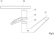
- FIG. 3 Finally, the structure of an inverted microscope 11 is sketched, with which the slide 1 can be used.
- the inverted microscope 11 has a sample table 12 above which a light source (not shown) is located.
- the slide mount 15 is thus rigidly arranged in the observation beam path between the objective turret 13 and an eyepiece tube 16, At the end of the eyepiece tube 16 there is an eyepiece holder 17 for holding eyepieces.
- the optical elements required for the PlasDIC observation method into a stack in which the individual elements - apart from the slit diaphragm - are fixed to one another, it is possible for a user to remove the entire stack from the beam path with one hand movement , whereas previously at least two steps were necessary. It is also possible to design a slide mount that is not coupled to the objective nosepiece, so that the stack can be used for several objectives. The stack can be interchanged so that a large number of lenses can be used with the same slider. With partially motorized microscopes and, in particular, with manually operated microscopes, the number of steps required to switch from PlasDIC to another observation method is significantly reduced. Due to the small number of components, use is also clearer and also reduces the possibility of incorrect operation.
Landscapes
- Physics & Mathematics (AREA)
- General Physics & Mathematics (AREA)
- Optics & Photonics (AREA)
- Chemical & Material Sciences (AREA)
- Analytical Chemistry (AREA)
- Microscoopes, Condenser (AREA)
- Investigating, Analyzing Materials By Fluorescence Or Luminescence (AREA)
Description
- Die Erfindung betrifft einen Schieber zum Einschieben in den Beobachtungsstrahlengang eines Mikroskops. Ein solcher Schieber umfasst eine erste Halterung, in der ein Stapel optischer Elemente für ein erstes Beobachtungsverfahren, nämlich ein polarisationsoptisches, differentielles Interferenzkontrastverfahren angeordnet ist. Der Stapel optischer Elemente umfasst einen Polarisator und polarisationsoptische Shearing-Elemente, beispielsweise in Form eines - aus mehreren einzelnen Prismen zusammengesetztes - Wollaston- oder modifizierten Wollastonprismas, insbesondere in Form eines Nomarskiprismas.
- Mikroskopisch zu untersuchende Objekte, insbesondere biologische Objekte lassen sich im wesentlichen in zwei Klassen einteilen, nämlich in Amplitudenobjekte und Phasenobjekte. Bei der mikroskopischen Untersuchung von Amplitudenobjekten verändern diese das Licht, welches zu ihrer Beleuchtung verwendet wird, in seiner Helligkeit bzw. Intensität, oder auch in der Wellenlänge, wenn beispielsweise Farbstoffe zur Emission angeregt werden. Amplitudenobjekte können auf diese Weise direkt sichtbar gemacht werden. Phasenobjekte hingegen ändern lediglich die Phasenlage des Lichtes, beispielsweise durch Abweichungen in der Brechzahl oder der Dicke relativ zur Umgebung, so dass eine direkte Wahrnehmung auch durch elektronische Bildsensoren nicht möglich ist. Allerdings können Phasenobjekte auch mit Fluoreszenzmarkern markiert sein, so dass sie auf diese Weise direkt sichtbar gemacht werden.
- Um unmarkierte Phasenobjekte sichtbar zu machen, wurden verschiedene mikroskopische Verfahren entwickelt, nämlich Phasenkontrast- und Interferenzkontrastverfahren.
- Eines der am häufigsten eingesetzten Interferenzkontrastverfahren ist das Differential-Interferenzkontrastverfahren (DIC) nach Smith und Nomarski. Dabei wird jeweils ein sogenanntes Nomarski-Prisma, bei dem es sich um eine Modifikation eines Wollastonprismas handelt, beleuchtungsseitig in der Kondensor-Brennebene und abbildungsseitig in der hinteren Objektiv-Brennebene in den Strahlengang eines Mikroskops eingebracht. In den Strahlengang vor dem ersten Nomarskiprisma wird ein Polarisator zur Erzeugung linear polarisierten Lichtes eingebracht. Nach dem Durchgang durch das zweite Nomarskiprisma wird das Licht mit Hilfe eines zweiten Polarisators, des Analysators, analysiert. Durch das beleuchtungsseitige Nomarskiprisma wird das Licht unabhängig vom Objekt in zwei kohärente Teilwellen aufgespalten, die beide vom Objekt beeinflusst werden. Durch das zweite Prisma werden die Teilstrahlen zusammengeführt und können hinter dem Analysator miteinander interferieren. Die Durchlassrichtungen von Polarisator und Analysator stehen senkrecht aufeinander. Nachteilig bei diesem Aufbau ist, dass sowohl das Objektiv als auch alle optischen Elemente im Beleuchtungsstrahlengang hinsichtlich der Polarisation isotropen Charakter aufweisen müssen, so dass keine doppelbrechenden Objektträger aus Kunststoff oder Objektive mit merklicher Spannungsdoppelbrechung verwendet werden können.
- Eine Weiterentwicklung dieses Verfahrens ist das sogenannte PlasDIC-Verfahren, welches beispielsweise in der
EP 1 359 453 B1 und in einem Artikel von R. Danz et al. in der Zeitschrift "Photonik", Ausgabe 1 / 2004 auf den Seiten 42-45 beschrieben ist. Auf beide Dokumente wird hinsichtlich der Beschreibung des PlasDIC-Verfahrens ausdrücklich Bezug genommen. Im Unterschied zum normalen DIC-Verfahren wird beim PlasDIC-Verfahren das linear polarisierte Licht erst unmittelbar vor dem abbildungsseitigen Nomarskiprisma erzeugt, wobei anstelle eines beleuchtungsseitigen Prismas eine Spaltblende eingesetzt wird. Die Breite des Spaltes ist für ein optimales Signal so zu wählen, dass der wirksame Pupillen-Gang-Unterschied in Richtung der Spaltbreite kleiner oder gleich einer Viertel-Wellenlänge bzw. einem Viertel des Interferenzstreifenabstandes in der Pupille ist. - Diese Art der Probenkontrastierung in der Bildgebung wird häufig kombiniert mit anderen Arten der Kontrastierung, beispielsweise mit einer Fluoreszenz-Kontrastierung. Um beispielsweise zwischen PlasDIC-Verfahren und einem Fluoreszenz-Kontrastverfahren zu wechseln, müssen mehrere Schritte unternommen werden: zunächst müssen Polarisator und Analysator aus dem Strahlengang genommen werden, um die auf den Detektor fallende Fluoreszenz nicht abzuschwächen. Um Doppelbilder zu vermeiden, müssen außerdem die interferometrisch wirkenden Komponenten, also beispielsweise das Wollaston- oder Nomarskiprisma, aus dem Strahlengang entfernt werden. Unter Umständen kann auch ein Objektivwechsel erforderlich sein. In Abhängigkeit von den verwendeten Fluoreszenzfarbstoffen müssen spezielle Anregungs- und Emissionsfilter in den Strahlengang eingebracht werden. Schließlich muss von einer Durchlichtbeleuchtung, wie sie im PlasDIC-Verfahren verwendet wird, auf Fluoreszenz-Auflichtbeleuchtung gewechselt werden.
- In motorischen Mikroskopen des obersten Preissegments kann dieser Wechsel der Komponenten automatisiert erfolgen. Bei Mikroskopen des mittleren bis unteren Preissegments - ein Beispiel ist das Axiovert 40 der Firma Carl Zeiss Microlmaging GmbH - wird auf die Motorisierung verzichtet, die meisten Wechselvorgänge müssen per Hand durchgeführt werden, was Zeit kostet und fehlerbehaftet ist.
- Die wesentlichen Komponenten für das PlasDIC-Verfahren sind Polarisator, Shearing-Elemente und Analysator. Der Analysator ist in der Regel in einem Filterrevolver oder Filterschieber angeordnet, der auch die Fluoreszenz-Emissionsfilter enthält und beim Wechsel der Beobachtungsverfahren mit diesen den aktiven Platz im Beobachtungsstrahlengang tauscht. Polarisator und Shearing-Elemente sind miteinander verkittet und werden als sogenanntes PlasDIC-Prisma zu einer Reihe von Objektiven angeboten. Da zum einen die Pupillenebene des Objektivs und die Interferenzebene des PlasDIC-Prismas zur Deckung gebracht werden müssen und deshalb beim Design des Prismas entsprechende Fertigungsparameter eingestellt werden müssen, und zum anderen die durch die Shearing-Elemente bewirkte Aufspaltung zur Brennweite des verwendeten Objektivs passen muss, ist ein solches PlasDIC-Prisma immer nur für eine begrenzte Zahl an Objektiven nutzbar.
- Aus diesem Grund werden die gängigen PlasDIC-Prismen im Beobachtungsstrahlengang direkt hinter dem Objektiv in den Strahlengang eingebracht. Bei der Verwendung von Objektivrevolvern für mehrere Objektive verfügen die Revolver über eine Aufnahme, die es ermöglicht, die Prismen direkt unterhalb der Objektiv-Anlagefläche in den Objektivrevolverteller einzusetzen. Sie bewegen sich dann im Objektivrevolverteller mit dem zugeordneten Objektiv mit. Die PlasDIC-Prismen sind dazu in der Regel in speziellen Schiebern angeordnet, wie sie beispielsweise auch in dem oben bereits erwähnten Artikel von R. Danz et al. beschrieben sind.
- In einigen Fällen kann ein PlasDIC-Prisma auch für mehrere Objektive verwendet werden. In diesem Fall kann das PlasDIC-Prisma auch in einer Ebene außerhalb des Objektivrevolvertellers positioniert werden, so dass es nicht mitbewegt wird, sobald ein Objektivwechsel erfolgt.
- Während der Wechsel zwischen den verschiedenen Beobachtungsverfahren bei motorisierten Mikroskopen automatisch erfolgt, werden bei zumindest teilmotorisierten Mikroskopen Filterrevolver, Objektivrevolver und / oder der Fokustrieb motorisch betrieben und automatisch über einen PC-Anschluss sowie entsprechende Programme bewegt. Das PlasDIC-Prisma - oder auch beim DIC-Verfahren das abbildungsseitige Normaskiprisma - muss jedoch auch im Falle einer Teilmotorisierung des Mikroskops manuell entfernt werden. Insbesondere bei Nutzung des PlasDIC-Verfahrens führt der verkittete Polarisator zu einer reduzierten Transmission von etwa 25% bei Verwendung eine Polymer-basierten Polarisators. Wird dieser Polarisator nicht entfernt, könnten Bediener die beobachtete verminderte Fluoreszenzintensität auf eine generelle Schwäche des Mikroskops zurückführen.
- Aufgabe der Erfindung ist es daher, einen Schieber der eingangs beschriebenen Art, der für die Durchführung des PlasDIC-Verfahrens geeignet ist, sowie ein entsprechendes Mikroskop dahingehend weiterzuentwickeln, dass die Anzahl der notwendigen Schritte zum Wechsel zwischen den verschiedenen Beobachtungsverfahren bei manuellen oder teilmotorisierten Mikroskopen reduziert wird. Auch die Anzahl der zu bewegenden Komponenten soll reduziert werden, sowie die Möglichkeit einer Fehlbedienung durch den Benutzer.
- Diese Aufgabe wird bei einem Schieber der eingangs beschriebenen Art dadurch gelöst, dass der Stapel optischer Elemente in der ersten Halterung einen Analysator umfasst, der im Stapel in bezug auf seine Polarisationsrichtung in einer fest vorgegebenen Orientierung hinsichtlich der Polarisationsrichtung des Polarisators angeordnet ist, wobei der Stapel optischer Elemente in der ersten Halterung auswechselbar angeordnet ist und der Schieber mindestens eine weitere Halterung zur Aufnahme optischer Elemente für mindestens ein weiteres Beobachtungsverfahren umfasst.
- Dadurch, dass das Paar aus Polarisator und Analysator fest zueinander steht, bleibt die Orientierung der Shearing-Elemente, also beispielsweise des Nomarskiprismas, relativ zu den Polarisationsrichtungen und damit zu den Durchlassrichtungen der beiden polarisierenden Elemente gleich. Beim Wechsel zwischen zwei Verfahren muss hier also keine Ausrichtung bzw. Justierung vorgenommen werden, einzig die kondensorseitige Spaltblende, die die λ/4-Bedingung erfüllt, muss in den Strahlengang eingebracht werden, was jedoch zum Beispiel bei einem Wechsel zwischen Fluoreszenz-Auflichtbeleuchtung einerseits und PlasDIC-Durchlichtbeleuchtung andererseits aufgrund des Wechsels der Beleuchtungsrichtung keiner Aktion bedarf. Die Durchlassrichtungen von Polarisator und Analysator können dabei beliebig zueinander festgelegt werden, vorzugsweise stehen sie jedoch gekreuzt zueinander im Winkel von 90° und gemeinsam unter 45° zur Aufspaltungsrichtung des Nomarskiprismas. Diese Orientierung gewährleistet den maximalen Kontrast.
- Die feste Orientierung der Durchlassrichtungen und Aufspaltungsrichtung zueinander ermöglicht es auch, die Richtung, in die der Schieber in das Mikroskop eingeschoben wird, und damit auch die Lage einer entsprechenden Schieberaufnahme im Mikroskop flexibler und prinzipiell beliebig zu wählen, was den Spielraum in bezug auf die Konstruktion erhöht. Über die Bewegung des Schiebers in Schieberichtung lässt sich die Kontrastierung über eine Gangunterschiedsbeeinflussung, bei der das Prisma senkrecht zur optischen Achse dezentriert wird, variieren. Bei Mikroskopen, wie sie im Stand der Technik zu finden sind, war dies bisher aufgrund der Trennung von Analysator einerseits, sowie Polarisator und Prisma andererseits nicht möglich.
- Der Stapel optischer Elemente ist in der ersten Halterung auswechselbar angeordnet, was es einerseits ermöglicht, PlasDIC-Stapel für verschiedene Objektivgruppen in den Schieber einzusetzen, andererseits aber auch die Möglichkeit schafft, mit entsprechenden Fassungen die PlasDIC-Stapel in verschiedenen Winkeln in den Schieber einzusetzen.
- Um schließlich das Umschalten auf ein anderes Beobachtungsverfahren zu ermöglichen, umfasst der Schieber mindestens eine weitere Halterung zur Aufnahme optischer Elmente für mindestens ein weiteres Beobachtungsverfahren. In eine zweite Halterung können beispielsweise ein Filter für die Fluoreszenzemission eingebracht werden, die Halterung kann auch frei bleiben, um eine Hellfeldbeleuchtung bei freiem Durchgang zu ermöglichen. Bei dem weiteren Beobachtungsverfahren kann es sich aber auch um ein übliches DIC-Verfahren beispielsweise nach Smith/Normaski handeln, oder aber auch um ein PlasDIC-Verfahren, welches mit anderen Parametern arbeitet, beispielsweise anderen Shearing-Elementen, anderen Polarisatoren / Analysatoren, wobei der Unterschied auch einfach nur in einer anderen Stellung der Durchlassrichtungen von Polarisator und Analysator liegen kann, oder in einem anderen Kippwinkel in bezug auf die optische Achse. Auch Variationen des PlasDIC-Verfahrens werden also unter dem Begriff "weiteres Beobachtungsverfahren" subsummiert. Selbstverständlich ist es auch möglich, den Schieber mit mehr als zwei Halterungen auszugestalten, sofern dies konstruktionstechnisch in bezug auf das Mikroskop, in das der Schieber eingesetzt werden soll, möglich ist. In der dritten Halterung können dann optische Elemente für ein drittes Beobachtungsverfahren angeordnet sein, beispielsweise ein Polarisator für eine Durchlicht-Beobachtung mit Polarisationskontrast.
- Mittels des erfindungsgemäßen Schiebers wird das Umschalten zwischen zwei verschiedenen Kontrastierungsverfahren, insbesondere zwischen einem PlasDIC-Verfahren und einem Fluoreszenzkontrastverfahren oder anderen Kontrastverfahren, die keine Polarisation benötigen, für den Bediener erleichtert, indem mit einer Handbewegung sowohl die Shearing-Elemente als auch beide polarisationsoptischen Elemente aus dem Strahlengang entfernt werden. Der Benutzer kann also nicht versehentlich vergessen, den Analysator und / oder den PlasDIC-Schieber ebenfalls aus dem Strahlengang zu entfernen, da dieser gleichzeitig mit den anderen Elementen entfernt wird. Der Stapel optischer Elemente kann auch problemlos gegen einen anderen Stapel ausgetauscht werden, der beispielsweise für eine andere Gruppe von Objektiven optimiert ist.
- Vorzugsweise sind die optischen Elemente des Stapels miteinander verkittet. Dies ermöglicht zum einen ein einfaches Auswechseln des Stapels gegen einen anderen und sorgt zum anderen zusätzlich dafür, dass die optische Wirkung sowie die Stellung der Durchlassrichtungen von Analysator und Polarisator permanent fixiert sind, da eine Verschiebung der einzelnen Elemente gegeneinander nicht möglich ist. Andererseits ist es auch möglich, die optischen Elemente jeweils einzeln oder in Gruppen zu fassen und dann die optischen Elemente in ihren Fassungen in einen entsprechend ausgestalteten Schieber einzusetzen. Dies ermöglicht beispielsweise ein Auswechseln der Shearing-Elemente unabhängig von Polarisator und Analysator oder auch die Verwendung anderer Polarisatoren und Analysatoren mit denselben Shearing-Elementen.
- Die Shearing-Elemente können beispielsweise zwei Keilprismen umfassen, die miteinander verkittet sind und bevorzugt ein Nomarskiprisma oder Wollastonprisma bilden. Es können jedoch auch mehr als zwei Prismen verwendet werden.
- Polarisator und Analysator bestehen bevorzugt jeweils aus einer Polyvinylalkohol-Folie (PVA-Folie). Auch die Verwendung von Polarisatoren und Analysatoren aus anderen Materialien, wie beispielsweise auf Basis von mit Metallpartikeln durchsetzten Gläsern oder Polarisatoren auf der Basis von Metallstreifengittern, sogenannten wire-grid-Polarisatoren ist möglich. Für den Fall, dass die Polare, d.h. Polarisator und Analysator, aus PVA-Folie bestehen, sind sie bevorzugt jeweils auf der den Shearing-Elementen abgewandten Seite mit einem Deckglas verkittet, welches die Polare vor Beschädigungen schützt. Bei der Verwendung anderer Materialien kann auf ein solches Deckglas gegebenenfalls auch verzichtet werden. Mit ihrer den Shearing-Elementen zugewandten Seite können die Polare auch mit diesem verkittet sein.
- Die erste Halterung, in die der Stapel optischer Elemente eingesetzt wird, ist bevorzugt als Einschubhalterung für einen Einschub ausgestaltet. In diesem Einschub werden die optischen Elemente des Stapels - bei verkitteten Elementen der Stapel selbst - gehalten, er dient als Fassung. Der Einschub kann dann in die Einschubhalterung eingeschoben werden, in der Regel entlang der Längsachse des Schiebers, die der Schubrichtung des eingesetzten Schiebers im Mikroskop entspricht.
- Der Stapel optischer Elemente ist dabei zu einem in die Einschubhalterung einzusetzenden Einschub zusammengefasst. Mit der Verwendung von Einschüben ist es möglich, beispielsweise verschiedene Kippungen des Stapels optischer Elemente zu realisieren, so dass die Kontrastierrichtung variiert werden kann. Zur Drehung des Stapels optischer Elemente für die Variation der Kontrastierrichtung wird der Stapel optischer Elemente einfach in einem anderen Einschub eingesetzt, mit dem eine andere Kippung realisiert wird, oder der Einschub wird gegen einen anderen ausgetauscht, falls die optischen Elemente beispielsweise durch Verklebung mit dem Einschub fest verbunden sind.
- Der Einschub ist dabei zweckmäßig mit einer Rändelschraube zur lateralen Verschiebung des Stapels optischer Elemente im Einschub ausgestattet. Damit lässt sich der Gangunterschied unabhängig von der Probe variieren. Der Einschub selbst kann im Schieber kraft- oder formschlüssig fixiert werden, beispielsweise mittels magnetischer Halterungen oder Schrauben.
- Die Erfindung betrifft auch ein Mikroskop mit einem erfindungsgemäßen Schieber, wie er vorangehend beschrieben wurde. Ein solches Mikroskop umfasst unter anderem einen Objektivrevolver mit mehreren Objektiven und eine Schieberaufnahme. In diese ist der Schieber auswechselbar und verschiebbar eingesetzt. Die Schieberaufnahme ist im Beobachtungsstrahlengang zwischen dem Objektivrevolver und einem Okulartubus starr angeordnet. Waren bisher entsprechende Schieber mit Stapeln optischer Elemente für das PlasDIC-Verfahren in den Objektivrevolver selbst einzusetzen, so ist die erfindungsgemäße Positionierung der Schieberaufnahme unabhängig vom Objektivrevolver und auch unabhängig von einem Filterrevolver oder Filterschieber, so dass ein Stapel optischer Elemente für das PlasDIC-Verfahren auch für mehrere Objektive genutzt werden kann. Außerdem wird bei der Beobachtung grundsätzlich auch eine gleichzeitige Aufnahme eines Fluoreszenzkontrast- und eines PlasDIC-Bildes ermöglicht, da die entsprechende Filterposition im Filterrevolver bzw. Filterschieber nicht durch den Analysator blockiert ist.
- Es versteht sich, dass die vorstehend genannten und die nachstehend noch zu erläuternden Merkmale nicht nur in den angegebenen Kombinationen, sondern auch in anderen Kombinationen oder in Alleinstellung einsetzbar sind, ohne den Rahmen der vorliegenden Erfindung zu verlassen.
- Nachfolgend wird die Erfindung beispielsweise anhand der beigefügten Zeichnungen, die auch erfindungswesentliche Merkmale offenbaren, noch näher erläutert. Es zeigen:
- Fig.1a
- eine Draufsicht auf einen Schieber,
- Fig.1b
- die Seitenansicht des Schiebers,
- Fig.2
- einen Schnitt durch einen Schieber und
- Fig. 3
- skizzenhaft ein inverses Mikroskop mit einer Schieberaufnahme.
- In
Fig.1 ist in einer Draufsicht ein Schieber 1 zum Einschieben in den Beobachtungsstrahlengang eines Mikroskops dargestellt. Dieser Schieber umfasst eine erste Halterung 2. In der ersten Halterung 2 ist ein Stapel optischer Elemente für ein erstes Beobachtungsverfahren, das PlasDIC-Verfahren, angeordnet. Der Stapel optischer Elemente in der ersten Halterung 2 umfasst einen Polarisator, polarisationsoptische Shearing-Elemente und einen Analysator. Der Analysator ist im Stapel in bezug auf seine Polarisationsrichtung in einer fest vorgegebenen Orientierung in bezug auf die Polarisationsrichtung des Polarisators angeordnet. Die Durchlassrichtungen der beiden Polare sind also zueinander fixiert. - Der Schieber 1 umfasst mindestens eine weitere Halterung für Aufnahme optischer Elemente für mindestens ein weiteres Beobachtungsverfahren. In dem in
Fig.1a gezeigten Beispiel umfasst der Schieber 1 zwei weitere Halterungen, nämlich eine zweite Halterung 3 und eine dritte Halterung 4. In der zweiten Halterung 3 können beispielsweise optische Elemente für eine Hellfeld-Beobachtung angeordnet sein. Auch die Anordnung eines Filters oder mehrerer Filter in der zweiten Halterung 3 ist eine Möglichkeit. Beispielsweise kann dort ein Fluoreszenz-Emissionsfilter angeordnet sein, der in einem Fluoreszenzkontrast-Beobachtungsverfahren verwendet werden kann. Dabei ist es nicht zwingend notwendig, dass in der zweiten Halterung 3 überhaupt ein optisches Element angeordnet ist. Auf ein solches kann beispielsweise verzichtet werden, wenn als zweites Beobachtungsverfahren eine einfache Durchlicht-Beobachtung durchgeführt werden soll. In der dritten Halterung 4 kann ein Polarisator für eine Durchlicht-Beobachtung mit Polarisationskontrast angeordnet sein, oder auch für ein übliches differentielles Interferenzkontrastverfahren nach Smith / Nomarski. Die genannte Aufzählung verschiedener Beobachtungsverfahren ist nur beispielhaft zu verstehen, es gibt eine Vielzahl weiterer Beobachtungsverfahren, für die in den Halterungen 3 und 4 optische Elemente angeordnet sein können. Auch die Anordnung eines weiteren Stapels optischer Elemente für das PlasDIC-Verfahren ist selbstverständlich möglich, beispielsweise mit Polarisatoren / Analysatoren aus anderen Materialien, oder anderen Shearing-Elementen. - Vorzugsweise wird man für die Variationen des PlasDIC-Beobachtungsverfahrens jedoch die Halterung 2 benutzen, da diese ein einfaches Auswechseln der optischen Elemente erlaubt. Die erste Halterung 2 ist dazu bevorzugt als Einschubhalterung ausgestaltet, der Stapel optischer Elemente ist zu einem in die Einschubhalterung einzusetzenden Einschub 7 zusammengefasst. Der Stapel optischer Elemente ist nach dem Einsetzen mit einer Rändelschraube 5 im Einschub 7 lateral verschiebbar. An den in
Fig.1b dargestellten Seitenflächen des Schiebers sind Nuten 6 angebracht, die in entsprechende, federnde Nasen in einer Schieberaufnahme im Mikroskop eingreifen und Rastpositionen definieren, an denen die Öffnungen der Halterungen 2, 3 und 4 jeweils im Beobachtungsstrahlengang des Mikroskops zentriert sind. - In
Fig.2 ist der Schieber 1 im Querschnitt entlang einer Linie AA, die inFig.1a eingezeichnet ist, gezeigt. Die optischen Elemente werden hier in einem Einschub 7 zusammengefasst, in welchem sie in einem festen Winkel relativ zur optischen Achse des Beobachtungsstrahlengangs angeordnet sind. Die optischen Elemente des Stapels inFig.2 sind in einem Winkel von etwas weniger als 10° zur optischen Achse angeordnet, was nur beispielhaft zu verstehen ist. Der Einschub 7 kann gegen andere Einschübe ausgewechselt werden, die die optischen Elemente in anderen Winkeln fassen. - Bei den optischen Elementen handelt es sich um die Shearing-Elemente, hier zwei miteinander verkittete Keilprismen 8a und 8b, welche zusammen ein Nomarskiprisma bilden. Die anderen, außen liegenden Flächen der Keilprismen sind mit Polaren verkittet. An der Außenfläche des Keilprismas 8a ist dieses mit einem Polarisator 9a verkittet, an der Außenfläche des Keilprismas 8b ist dieses mit einem Analysator 9b verkittet. Im dargestellten Beispiel ist der Querschnitt des Schiebers gezeigt, wie er in einem Mikroskop zur inversen Beobachtung aufgenommen wird. Polarisator 9a und Analysator 9b können beispielsweise aus PVA-Folie hergestellt sein, jedoch ist auch die Verwendung anderer Materialen möglich. Die Durchlassrichtungen von Polarisator und Analysator stehen vorzugsweise gekreuzt zueinander im Winkel von 90°. Auf diese Weise wird maximaler Kontrast gewährleistet. Je nachdem, aus welchem Material die Polare bestehen, können sie - wie im vorliegenden Fall - noch mit Deckgläsern 10a und 10b verkittet sein, und zwar jeweils auf der dem jeweiligen Prisma abgewandten Seite. Anstelle alle oder auch nur einzelne optische Elemente miteinander zu verkitten ist es auch möglich, die Elemente einzeln einzufassen und in einen entsprechend dafür hergerichteten Einschub einzusetzen. Dies ermöglicht bei Bedarf den Austausch einzelner Elemente unabhängig von den anderen.
- In
Fig.3 schließlich ist der Aufbau eines inversen Mikroskops 11 skizziert, mit welchem der Schieber 1 verwendet werden kann. Das inverse Mikroskop 11 verfügt über einen Probentisch 12, oberhalb dessen sich eine nichtgezeigte Lichtquelle befindet. Unterhalb des Probentisches 12 ist ein Objektivrevolver 13 angeordnet, in den ein Objektiv 14 eingesetzt ist, welches außerdem in den Beobachtungsstrahlengang eingeschwenkt wurde. Unterhalb des Objektivrevolvers 13 befindet sich eine Schieberaufnahme 15, in die der Schieber 1 auswechselbar eingesetzt werden kann. Die Schieberaufnahme 15 ist also im Beobachtungsstrahlengang zwischen dem Objektivrevolver 13 und einem Okulartubus 16 starr angeordnet, am Ende des Okulartubus 16 befindet sich eine Okularhalterung 17 zur Aufnahme von Okularen. - Durch die Zusammenfassung der für das PlasDIC-Beobachtungsverfahren notwendigen optischen Elemente zu einem Stapel, in dem die einzelnen Elemente - abgesehen von der Spaltblende - fest zu einander angeordnet sind, wird es einem Benutzer ermöglicht, mit einer Handbewegung den gesamten Stapel aus den Strahlengang zu entfernen, wohingegen bisher mindestens zwei Handgriffe notwendig waren. Außerdem ist es möglich, eine Schieberaufnahme zu gestalten, die nicht an den Objektivrevolver gekoppelt ist, so dass der Stapel für mehrere Objektive genutzt werden kann. Der Stapel kann ausgewechselt werden, so dass eine Vielzahl von Objektiven mit dem gleichen Schieber benutzt werden kann. Bei teilmotorisierten und insbesondere bei manuell zu bedienenden Mikroskopen wird die Anzahl der notwendigen Schritte für einen Wechsel von PlasDIC-Verfahren zu einem anderen Beobachtungsverfahren somit deutlich reduziert. Aufgrund der geringen Anzahl der Komponenten gestaltet sich die Benutzung außerdem übersichtlicher und verringert zudem die Möglichkeit einer Fehlbedienung.
-
- 1
- Schieber
- 2
- erste Halterung
- 3
- zweiter Halterung
- 4
- dritte Halterung
- 5
- Rändelschraube
- 6
- Nut
- 7
- Einschub
- 8a, 8b
- Keilprisma
- 9a
- Polarisator
- 9b
- Analysator
- 10a, 10b
- Deckglas
- 11
- Mikroskop
- 12
- Probentisch
- 13
- Objektivrevolver
- 14
- Objektiv
- 15
- Schieberaufnahme
- 16
- Okulartubus
- 17
- Okularhalterung
Claims (9)
- Schieber (1) zum Einschieben in den Beobachtungsstrahlengang eines Mikroskops (11), umfassend eine erste Halterung (2) und einen Stapel optischer Elemente,- wobei in der ersten Halterung (2) der Stapel optischer Elemente für ein polarisationsoptisches, differentielles Interferenzkontrastverfahren als ein erstes Beobachtungsverfahren angeordnet ist, wobei der Stapel einen Polarisator (9a) und polarisationsoptische Shearing-Elemente umfasst, dadurch gekennzeichnet, dass- der Stapel optischer Elemente in der ersten Halterung (2) einen Analysator (9b) umfasst, der im Stapel in Bezug auf seine Polarisationsrichtung in einer fest vorgegebenen Orientierung in Bezug auf die Polarisationsrichtung des Polarisators (9a) angeordnet ist,- die erste Halterung (2) als Einschubhalterung ausgestaltet ist, und der Stapel optischer Elemente zu einem in die Einschubhalterung einzusetzenden Einschub (7) zusammengefasst ist, wodurch der Stapel optischer Elemente in der ersten Halterung (2) auswechselbar angeordnet ist,- und der Schieber (1) mindestens eine weitere Halterung zur Aufnahme optischer Elemente für mindestens ein weiteres Beobachtungsverfahren umfasst.
- Schieber (1) nach Anspruch 1, dadurch gekennzeichnet, dass die optischen Elemente des Stapels miteinander verkittet sind.
- Schieber (1) nach Anspruch 1 oder 2, dadurch gekennzeichnet, dass der Einschub (7) mit einer Rändelschraube (5) zur lateralen Verschiebung des Stapels optischer Elemente im Einschub (7) ausgestaltet ist.
- Schieber (1) nach einem der Ansprüche 1 bis 3, dadurch gekennzeichnet, dass die Shearing-Elemente zwei, bevorzugt miteinander verkittete, Keilprismen (8a, 8b) umfassen, welche bevorzugt ein Nomarskiprisma oder Wollastonprisma bilden.
- Schieber nach einem der Ansprüche 1 bis 4, dadurch gekennzeichnet, dass Polarisator (9a) und Analysator (9b) aus Polyvinylalkohol-Folie bestehen.
- Schieber (1) nach einem der Ansprüche 1 bis 5, dadurch gekennzeichnet, dass Polarisator (9a) und / oder Analysator (9b) mit den Shearing-Elementen verkittet sind, und/oder ihre den Shearing-Elementen abgewandten Seiten mit einem Deckglas (10a, 10b) verkittet sind.
- Schieber (1) nach einem der Ansprüche 1 bis 6, dadurch gekennzeichnet, dass als weitere Halterungen eine zweite Halterung (3) und eine dritte Halterung (4) vorgesehen sind, und in der zweiten Halterung (3) optische Elemente für eine Hellfeld-Beobachtung, ein oder mehrere Filter oder kein optisches Element angeordnet sind.
- Schieber (1) nach Anspruch 7, dadurch gekennzeichnet, dass in der dritten Halterung (4) ein Polarisator für eine Durchlicht-Beobachtung mit Polarisationskontrast oder für ein differentielles Interferenzkontrastverfahren angeordnet ist.
- Mikroskop mit einem Schieber (1) nach einem der Ansprüche 1 bis 8, umfassend einen Objektivrevolver (13) und eine Schieberaufnahme (15), in die der Schieber (1) auswechselbar eingesetzt ist, wobei die Schieberaufnahme (15) im Beobachtungsstrahlengang zwischen dem Objektivrevolver (13) und einem Okulartubus (16) starr angeordnet ist.
Applications Claiming Priority (2)
| Application Number | Priority Date | Filing Date | Title |
|---|---|---|---|
| DE102011006667A DE102011006667A1 (de) | 2011-04-01 | 2011-04-01 | Schieber zum Einschieben in den Beobachtungsstrahlengang eines Mikroskops |
| PCT/EP2012/053240 WO2012130542A1 (de) | 2011-04-01 | 2012-02-27 | Schieber zum einschieben in den beobachtungsstrahlengang eines mikroskops |
Publications (2)
| Publication Number | Publication Date |
|---|---|
| EP2695013A1 EP2695013A1 (de) | 2014-02-12 |
| EP2695013B1 true EP2695013B1 (de) | 2021-01-06 |
Family
ID=45808817
Family Applications (1)
| Application Number | Title | Priority Date | Filing Date |
|---|---|---|---|
| EP12707074.6A Not-in-force EP2695013B1 (de) | 2011-04-01 | 2012-02-27 | Schieber zum einschieben in den beobachtungsstrahlengang eines mikroskops |
Country Status (4)
| Country | Link |
|---|---|
| US (1) | US9405111B2 (de) |
| EP (1) | EP2695013B1 (de) |
| DE (1) | DE102011006667A1 (de) |
| WO (1) | WO2012130542A1 (de) |
Families Citing this family (1)
| Publication number | Priority date | Publication date | Assignee | Title |
|---|---|---|---|---|
| RU2718427C2 (ru) * | 2015-07-16 | 2020-04-02 | Конинклейке Филипс Н.В. | Система цифровой патологии |
Family Cites Families (10)
| Publication number | Priority date | Publication date | Assignee | Title |
|---|---|---|---|---|
| US4255014A (en) * | 1977-07-20 | 1981-03-10 | Research Corporation | Edge enhancement of phase phenomena |
| JP2001091835A (ja) * | 1999-09-17 | 2001-04-06 | Olympus Optical Co Ltd | 光学顕微鏡装置 |
| JP4608043B2 (ja) * | 1999-09-24 | 2011-01-05 | オリンパス株式会社 | 顕微鏡用焦点検出装置 |
| DE10219804A1 (de) | 2002-04-30 | 2003-11-13 | Zeiss Carl Jena Gmbh | Anordnung und Verfahren zum polarisationsoptischen Interferenzkontrast |
| US6924893B2 (en) * | 2002-05-13 | 2005-08-02 | Marine Biological Laboratory | Enhancing polarized light microscopy |
| DE10321091B4 (de) * | 2003-05-09 | 2005-06-30 | Leica Microsystems Wetzlar Gmbh | Mikroskop und Mikroskopierverfahren zur Erzeugung von Überlagerungsbildern |
| DE102004048300B4 (de) * | 2004-10-01 | 2019-04-18 | Carl Zeiss Microscopy Gmbh | Prismenwechseleinrichtung und Mikroskop mit Prismenwechseleinrichtung |
| DE102004061901B4 (de) * | 2004-10-18 | 2008-11-06 | Leica Microsystems Cms Gmbh | Einrichtung zur Halterung von optischen Komponenten |
| DE102006024109A1 (de) * | 2006-05-19 | 2007-11-22 | Carl Zeiss Microimaging Gmbh | Mikroskop mit Wechseleinrichtung für optische Elemente |
| JP4914655B2 (ja) * | 2006-06-26 | 2012-04-11 | オリンパス株式会社 | 顕微鏡構成ユニット、該顕微鏡構成ユニットよりなる顕微鏡システム、及び顕微鏡システムを構築する顕微鏡構成ユニットの相対的接続関係取得方法 |
-
2011
- 2011-04-01 DE DE102011006667A patent/DE102011006667A1/de not_active Ceased
-
2012
- 2012-02-27 WO PCT/EP2012/053240 patent/WO2012130542A1/de not_active Ceased
- 2012-02-27 EP EP12707074.6A patent/EP2695013B1/de not_active Not-in-force
- 2012-02-27 US US14/008,999 patent/US9405111B2/en active Active
Non-Patent Citations (1)
| Title |
|---|
| None * |
Also Published As
| Publication number | Publication date |
|---|---|
| US20140153088A1 (en) | 2014-06-05 |
| WO2012130542A1 (de) | 2012-10-04 |
| US9405111B2 (en) | 2016-08-02 |
| DE102011006667A1 (de) | 2012-10-04 |
| EP2695013A1 (de) | 2014-02-12 |
Similar Documents
| Publication | Publication Date | Title |
|---|---|---|
| DE102010062341B4 (de) | Vorrichtung zur Erhöhung der Tiefendiskriminierung optisch abbildender Systeme | |
| DE102018210603B4 (de) | Verfahren zum Erzeugen eines Übersichtsbilds unter Verwendung eines hochaperturigen Objektivs | |
| EP2480926B1 (de) | Mikroskop | |
| DE102006036300B4 (de) | Hochleistungs-Stereomikroskop | |
| DE102012017917B4 (de) | Mikroskopmodul und Lichtmikroskop sowie Verfahren und Datenspeicherträger | |
| DE102012017920B4 (de) | Optikanordnung und Lichtmikroskop | |
| DE102010039950B4 (de) | Mikroskop mit Mikro- und Makro-Objektiven | |
| DE102012020240A1 (de) | Mikroskop und Verfahren zur SPIM Mikroskopie | |
| DE102012110077A1 (de) | Mikroskop mit mindestens einem Beleuchtungsstrahl in Form einer Lichtscheibe | |
| DE102017119478A1 (de) | Optische Anordnung zum Scannen von Anregungsstrahlung und/oder Manipulationsstrahlung in einem Laser-Scanning-Mikroskop und Laser-Scanning-Mikroskop | |
| DE102014110606B4 (de) | Mikroskop mit einer Strahlteileranordnung | |
| WO2011018181A1 (de) | Mikroskop zur messung von totalreflexions-fluoreszenz | |
| WO2016166375A1 (de) | Verfahren und vorrichtung zum untersuchen eines objektes, insbesondere einer mikroskopischen probe | |
| WO2017194742A1 (de) | Optisches rastermikroskop und untersuchungsverfahren | |
| DE4331570A1 (de) | Verfahren und Vorrichtung zum optischen Anregen eines Energiezustands einer Probe in einem Probenpunkt mit hoher Ortsauflösung | |
| EP3440492B1 (de) | Verfahren und mikroskop zum untersuchen einer probe | |
| DE10321091B4 (de) | Mikroskop und Mikroskopierverfahren zur Erzeugung von Überlagerungsbildern | |
| DE102005005757B4 (de) | Anordnung zur mikroskop-optischen Erfassung von Anisotropien | |
| DE4404286A1 (de) | Fluoreszenzeinrichtung für Invers-Mikroskope | |
| DE102016211374A1 (de) | Mikroskopieverfahren unter Nutzung zeitlicher Fokusmodulation und Mikroskop | |
| EP1359453A2 (de) | Anordnung und Verfahren zum polarisationsoptischen Interferenzkontrast | |
| EP2695013A1 (de) | Schieber zum einschieben in den beobachtungsstrahlengang eines mikroskops | |
| DE3127509C2 (de) | Fokussierungsvorrichtung für Mikroskope | |
| DE102014203656B4 (de) | Lasermikrodissektionsverfahren und Verwendung eines Lasermikrodissektionssystems | |
| DE102006017350B4 (de) | Abbildungsvorrichtung zum Abbilden mikroskopischer oder makroskopischer Objekte |
Legal Events
| Date | Code | Title | Description |
|---|---|---|---|
| PUAI | Public reference made under article 153(3) epc to a published international application that has entered the european phase |
Free format text: ORIGINAL CODE: 0009012 |
|
| 17P | Request for examination filed |
Effective date: 20130712 |
|
| AK | Designated contracting states |
Kind code of ref document: A1 Designated state(s): AL AT BE BG CH CY CZ DE DK EE ES FI FR GB GR HR HU IE IS IT LI LT LU LV MC MK MT NL NO PL PT RO RS SE SI SK SM TR |
|
| DAX | Request for extension of the european patent (deleted) | ||
| STAA | Information on the status of an ep patent application or granted ep patent |
Free format text: STATUS: EXAMINATION IS IN PROGRESS |
|
| 17Q | First examination report despatched |
Effective date: 20180723 |
|
| GRAP | Despatch of communication of intention to grant a patent |
Free format text: ORIGINAL CODE: EPIDOSNIGR1 |
|
| STAA | Information on the status of an ep patent application or granted ep patent |
Free format text: STATUS: GRANT OF PATENT IS INTENDED |
|
| INTG | Intention to grant announced |
Effective date: 20200917 |
|
| GRAS | Grant fee paid |
Free format text: ORIGINAL CODE: EPIDOSNIGR3 |
|
| GRAA | (expected) grant |
Free format text: ORIGINAL CODE: 0009210 |
|
| STAA | Information on the status of an ep patent application or granted ep patent |
Free format text: STATUS: THE PATENT HAS BEEN GRANTED |
|
| AK | Designated contracting states |
Kind code of ref document: B1 Designated state(s): AL AT BE BG CH CY CZ DE DK EE ES FI FR GB GR HR HU IE IS IT LI LT LU LV MC MK MT NL NO PL PT RO RS SE SI SK SM TR |
|
| REG | Reference to a national code |
Ref country code: GB Ref legal event code: FG4D Free format text: NOT ENGLISH |
|
| REG | Reference to a national code |
Ref country code: AT Ref legal event code: REF Ref document number: 1352994 Country of ref document: AT Kind code of ref document: T Effective date: 20210115 Ref country code: CH Ref legal event code: EP |
|
| REG | Reference to a national code |
Ref country code: DE Ref legal event code: R096 Ref document number: 502012016569 Country of ref document: DE |
|
| REG | Reference to a national code |
Ref country code: IE Ref legal event code: FG4D Free format text: LANGUAGE OF EP DOCUMENT: GERMAN |
|
| REG | Reference to a national code |
Ref country code: NL Ref legal event code: MP Effective date: 20210106 |
|
| REG | Reference to a national code |
Ref country code: LT Ref legal event code: MG9D |
|
| PG25 | Lapsed in a contracting state [announced via postgrant information from national office to epo] |
Ref country code: FI Free format text: LAPSE BECAUSE OF FAILURE TO SUBMIT A TRANSLATION OF THE DESCRIPTION OR TO PAY THE FEE WITHIN THE PRESCRIBED TIME-LIMIT Effective date: 20210106 Ref country code: GR Free format text: LAPSE BECAUSE OF FAILURE TO SUBMIT A TRANSLATION OF THE DESCRIPTION OR TO PAY THE FEE WITHIN THE PRESCRIBED TIME-LIMIT Effective date: 20210407 Ref country code: HR Free format text: LAPSE BECAUSE OF FAILURE TO SUBMIT A TRANSLATION OF THE DESCRIPTION OR TO PAY THE FEE WITHIN THE PRESCRIBED TIME-LIMIT Effective date: 20210106 Ref country code: PT Free format text: LAPSE BECAUSE OF FAILURE TO SUBMIT A TRANSLATION OF THE DESCRIPTION OR TO PAY THE FEE WITHIN THE PRESCRIBED TIME-LIMIT Effective date: 20210506 Ref country code: LT Free format text: LAPSE BECAUSE OF FAILURE TO SUBMIT A TRANSLATION OF THE DESCRIPTION OR TO PAY THE FEE WITHIN THE PRESCRIBED TIME-LIMIT Effective date: 20210106 Ref country code: BG Free format text: LAPSE BECAUSE OF FAILURE TO SUBMIT A TRANSLATION OF THE DESCRIPTION OR TO PAY THE FEE WITHIN THE PRESCRIBED TIME-LIMIT Effective date: 20210406 Ref country code: NO Free format text: LAPSE BECAUSE OF FAILURE TO SUBMIT A TRANSLATION OF THE DESCRIPTION OR TO PAY THE FEE WITHIN THE PRESCRIBED TIME-LIMIT Effective date: 20210406 Ref country code: NL Free format text: LAPSE BECAUSE OF FAILURE TO SUBMIT A TRANSLATION OF THE DESCRIPTION OR TO PAY THE FEE WITHIN THE PRESCRIBED TIME-LIMIT Effective date: 20210106 |
|
| PG25 | Lapsed in a contracting state [announced via postgrant information from national office to epo] |
Ref country code: LV Free format text: LAPSE BECAUSE OF FAILURE TO SUBMIT A TRANSLATION OF THE DESCRIPTION OR TO PAY THE FEE WITHIN THE PRESCRIBED TIME-LIMIT Effective date: 20210106 Ref country code: RS Free format text: LAPSE BECAUSE OF FAILURE TO SUBMIT A TRANSLATION OF THE DESCRIPTION OR TO PAY THE FEE WITHIN THE PRESCRIBED TIME-LIMIT Effective date: 20210106 Ref country code: PL Free format text: LAPSE BECAUSE OF FAILURE TO SUBMIT A TRANSLATION OF THE DESCRIPTION OR TO PAY THE FEE WITHIN THE PRESCRIBED TIME-LIMIT Effective date: 20210106 Ref country code: SE Free format text: LAPSE BECAUSE OF FAILURE TO SUBMIT A TRANSLATION OF THE DESCRIPTION OR TO PAY THE FEE WITHIN THE PRESCRIBED TIME-LIMIT Effective date: 20210106 |
|
| PG25 | Lapsed in a contracting state [announced via postgrant information from national office to epo] |
Ref country code: IS Free format text: LAPSE BECAUSE OF FAILURE TO SUBMIT A TRANSLATION OF THE DESCRIPTION OR TO PAY THE FEE WITHIN THE PRESCRIBED TIME-LIMIT Effective date: 20210506 |
|
| REG | Reference to a national code |
Ref country code: DE Ref legal event code: R097 Ref document number: 502012016569 Country of ref document: DE |
|
| REG | Reference to a national code |
Ref country code: BE Ref legal event code: MM Effective date: 20210228 |
|
| PG25 | Lapsed in a contracting state [announced via postgrant information from national office to epo] |
Ref country code: EE Free format text: LAPSE BECAUSE OF FAILURE TO SUBMIT A TRANSLATION OF THE DESCRIPTION OR TO PAY THE FEE WITHIN THE PRESCRIBED TIME-LIMIT Effective date: 20210106 Ref country code: CZ Free format text: LAPSE BECAUSE OF FAILURE TO SUBMIT A TRANSLATION OF THE DESCRIPTION OR TO PAY THE FEE WITHIN THE PRESCRIBED TIME-LIMIT Effective date: 20210106 Ref country code: LI Free format text: LAPSE BECAUSE OF NON-PAYMENT OF DUE FEES Effective date: 20210228 Ref country code: LU Free format text: LAPSE BECAUSE OF NON-PAYMENT OF DUE FEES Effective date: 20210227 Ref country code: MC Free format text: LAPSE BECAUSE OF FAILURE TO SUBMIT A TRANSLATION OF THE DESCRIPTION OR TO PAY THE FEE WITHIN THE PRESCRIBED TIME-LIMIT Effective date: 20210106 Ref country code: SM Free format text: LAPSE BECAUSE OF FAILURE TO SUBMIT A TRANSLATION OF THE DESCRIPTION OR TO PAY THE FEE WITHIN THE PRESCRIBED TIME-LIMIT Effective date: 20210106 Ref country code: CH Free format text: LAPSE BECAUSE OF NON-PAYMENT OF DUE FEES Effective date: 20210228 |
|
| PLBE | No opposition filed within time limit |
Free format text: ORIGINAL CODE: 0009261 |
|
| STAA | Information on the status of an ep patent application or granted ep patent |
Free format text: STATUS: NO OPPOSITION FILED WITHIN TIME LIMIT |
|
| PG25 | Lapsed in a contracting state [announced via postgrant information from national office to epo] |
Ref country code: RO Free format text: LAPSE BECAUSE OF FAILURE TO SUBMIT A TRANSLATION OF THE DESCRIPTION OR TO PAY THE FEE WITHIN THE PRESCRIBED TIME-LIMIT Effective date: 20210106 Ref country code: SK Free format text: LAPSE BECAUSE OF FAILURE TO SUBMIT A TRANSLATION OF THE DESCRIPTION OR TO PAY THE FEE WITHIN THE PRESCRIBED TIME-LIMIT Effective date: 20210106 Ref country code: ES Free format text: LAPSE BECAUSE OF FAILURE TO SUBMIT A TRANSLATION OF THE DESCRIPTION OR TO PAY THE FEE WITHIN THE PRESCRIBED TIME-LIMIT Effective date: 20210106 Ref country code: DK Free format text: LAPSE BECAUSE OF FAILURE TO SUBMIT A TRANSLATION OF THE DESCRIPTION OR TO PAY THE FEE WITHIN THE PRESCRIBED TIME-LIMIT Effective date: 20210106 |
|
| 26N | No opposition filed |
Effective date: 20211007 |
|
| GBPC | Gb: european patent ceased through non-payment of renewal fee |
Effective date: 20210406 |
|
| PG25 | Lapsed in a contracting state [announced via postgrant information from national office to epo] |
Ref country code: AL Free format text: LAPSE BECAUSE OF FAILURE TO SUBMIT A TRANSLATION OF THE DESCRIPTION OR TO PAY THE FEE WITHIN THE PRESCRIBED TIME-LIMIT Effective date: 20210106 Ref country code: GB Free format text: LAPSE BECAUSE OF NON-PAYMENT OF DUE FEES Effective date: 20210406 Ref country code: IE Free format text: LAPSE BECAUSE OF NON-PAYMENT OF DUE FEES Effective date: 20210227 Ref country code: FR Free format text: LAPSE BECAUSE OF NON-PAYMENT OF DUE FEES Effective date: 20210306 |
|
| PG25 | Lapsed in a contracting state [announced via postgrant information from national office to epo] |
Ref country code: SI Free format text: LAPSE BECAUSE OF FAILURE TO SUBMIT A TRANSLATION OF THE DESCRIPTION OR TO PAY THE FEE WITHIN THE PRESCRIBED TIME-LIMIT Effective date: 20210106 |
|
| REG | Reference to a national code |
Ref country code: AT Ref legal event code: MM01 Ref document number: 1352994 Country of ref document: AT Kind code of ref document: T Effective date: 20210227 |
|
| PG25 | Lapsed in a contracting state [announced via postgrant information from national office to epo] |
Ref country code: IT Free format text: LAPSE BECAUSE OF FAILURE TO SUBMIT A TRANSLATION OF THE DESCRIPTION OR TO PAY THE FEE WITHIN THE PRESCRIBED TIME-LIMIT Effective date: 20210106 Ref country code: AT Free format text: LAPSE BECAUSE OF NON-PAYMENT OF DUE FEES Effective date: 20210227 |
|
| PGFP | Annual fee paid to national office [announced via postgrant information from national office to epo] |
Ref country code: DE Payment date: 20220217 Year of fee payment: 11 |
|
| PG25 | Lapsed in a contracting state [announced via postgrant information from national office to epo] |
Ref country code: IS Free format text: LAPSE BECAUSE OF FAILURE TO SUBMIT A TRANSLATION OF THE DESCRIPTION OR TO PAY THE FEE WITHIN THE PRESCRIBED TIME-LIMIT Effective date: 20210506 |
|
| PG25 | Lapsed in a contracting state [announced via postgrant information from national office to epo] |
Ref country code: BE Free format text: LAPSE BECAUSE OF NON-PAYMENT OF DUE FEES Effective date: 20210228 |
|
| PG25 | Lapsed in a contracting state [announced via postgrant information from national office to epo] |
Ref country code: HU Free format text: LAPSE BECAUSE OF FAILURE TO SUBMIT A TRANSLATION OF THE DESCRIPTION OR TO PAY THE FEE WITHIN THE PRESCRIBED TIME-LIMIT; INVALID AB INITIO Effective date: 20120227 Ref country code: CY Free format text: LAPSE BECAUSE OF FAILURE TO SUBMIT A TRANSLATION OF THE DESCRIPTION OR TO PAY THE FEE WITHIN THE PRESCRIBED TIME-LIMIT Effective date: 20210106 |
|
| REG | Reference to a national code |
Ref country code: DE Ref legal event code: R119 Ref document number: 502012016569 Country of ref document: DE |
|
| PG25 | Lapsed in a contracting state [announced via postgrant information from national office to epo] |
Ref country code: DE Free format text: LAPSE BECAUSE OF NON-PAYMENT OF DUE FEES Effective date: 20230901 |
|
| PG25 | Lapsed in a contracting state [announced via postgrant information from national office to epo] |
Ref country code: MK Free format text: LAPSE BECAUSE OF FAILURE TO SUBMIT A TRANSLATION OF THE DESCRIPTION OR TO PAY THE FEE WITHIN THE PRESCRIBED TIME-LIMIT Effective date: 20210106 |
|
| PG25 | Lapsed in a contracting state [announced via postgrant information from national office to epo] |
Ref country code: TR Free format text: LAPSE BECAUSE OF FAILURE TO SUBMIT A TRANSLATION OF THE DESCRIPTION OR TO PAY THE FEE WITHIN THE PRESCRIBED TIME-LIMIT Effective date: 20210106 |
|
| PG25 | Lapsed in a contracting state [announced via postgrant information from national office to epo] |
Ref country code: MT Free format text: LAPSE BECAUSE OF FAILURE TO SUBMIT A TRANSLATION OF THE DESCRIPTION OR TO PAY THE FEE WITHIN THE PRESCRIBED TIME-LIMIT Effective date: 20210106 |