EP2694848B1 - Soupape de régulation hydroélectrique pour emplacements distants - Google Patents
Soupape de régulation hydroélectrique pour emplacements distants Download PDFInfo
- Publication number
- EP2694848B1 EP2694848B1 EP11862941.9A EP11862941A EP2694848B1 EP 2694848 B1 EP2694848 B1 EP 2694848B1 EP 11862941 A EP11862941 A EP 11862941A EP 2694848 B1 EP2694848 B1 EP 2694848B1
- Authority
- EP
- European Patent Office
- Prior art keywords
- fluid
- channel
- valve
- bell
- reservoir
- Prior art date
- Legal status (The legal status is an assumption and is not a legal conclusion. Google has not performed a legal analysis and makes no representation as to the accuracy of the status listed.)
- Active
Links
- 239000012530 fluid Substances 0.000 claims description 299
- 230000004913 activation Effects 0.000 claims description 37
- 238000004891 communication Methods 0.000 claims description 19
- 230000033001 locomotion Effects 0.000 claims description 18
- 230000009849 deactivation Effects 0.000 claims description 11
- 239000007789 gas Substances 0.000 claims description 11
- XLYOFNOQVPJJNP-UHFFFAOYSA-N water Substances O XLYOFNOQVPJJNP-UHFFFAOYSA-N 0.000 claims description 9
- 230000002547 anomalous effect Effects 0.000 claims description 3
- 239000010865 sewage Substances 0.000 claims description 3
- 239000002002 slurry Substances 0.000 claims description 3
- 235000013334 alcoholic beverage Nutrition 0.000 claims description 2
- 239000012267 brine Substances 0.000 claims description 2
- 238000012544 monitoring process Methods 0.000 claims description 2
- HPALAKNZSZLMCH-UHFFFAOYSA-M sodium;chloride;hydrate Chemical compound O.[Na+].[Cl-] HPALAKNZSZLMCH-UHFFFAOYSA-M 0.000 claims description 2
- 230000001476 alcoholic effect Effects 0.000 claims 1
- 235000019520 non-alcoholic beverage Nutrition 0.000 claims 1
- 238000004519 manufacturing process Methods 0.000 description 14
- VNWKTOKETHGBQD-UHFFFAOYSA-N methane Chemical compound C VNWKTOKETHGBQD-UHFFFAOYSA-N 0.000 description 8
- 239000012190 activator Substances 0.000 description 7
- 230000006378 damage Effects 0.000 description 7
- 238000007789 sealing Methods 0.000 description 7
- 230000003247 decreasing effect Effects 0.000 description 5
- 238000005553 drilling Methods 0.000 description 5
- 230000001965 increasing effect Effects 0.000 description 5
- 230000008859 change Effects 0.000 description 4
- 238000013461 design Methods 0.000 description 4
- 230000009977 dual effect Effects 0.000 description 4
- 230000007246 mechanism Effects 0.000 description 4
- 239000003345 natural gas Substances 0.000 description 4
- 230000004044 response Effects 0.000 description 4
- 230000000903 blocking effect Effects 0.000 description 3
- 238000004140 cleaning Methods 0.000 description 3
- 230000000694 effects Effects 0.000 description 3
- 238000000034 method Methods 0.000 description 3
- 241000191291 Abies alba Species 0.000 description 2
- 241000156978 Erebia Species 0.000 description 2
- 239000008186 active pharmaceutical agent Substances 0.000 description 2
- 230000003749 cleanliness Effects 0.000 description 2
- 238000013016 damping Methods 0.000 description 2
- 238000005265 energy consumption Methods 0.000 description 2
- 238000002347 injection Methods 0.000 description 2
- 239000007924 injection Substances 0.000 description 2
- 239000007788 liquid Substances 0.000 description 2
- 238000003825 pressing Methods 0.000 description 2
- 230000008439 repair process Effects 0.000 description 2
- 238000012216 screening Methods 0.000 description 2
- 238000003860 storage Methods 0.000 description 2
- 238000011144 upstream manufacturing Methods 0.000 description 2
- 208000001836 Firesetting Behavior Diseases 0.000 description 1
- 229910000831 Steel Inorganic materials 0.000 description 1
- 230000003213 activating effect Effects 0.000 description 1
- 235000013405 beer Nutrition 0.000 description 1
- 239000002775 capsule Substances 0.000 description 1
- 230000008602 contraction Effects 0.000 description 1
- 230000007423 decrease Effects 0.000 description 1
- 230000003111 delayed effect Effects 0.000 description 1
- 238000011161 development Methods 0.000 description 1
- 230000018109 developmental process Effects 0.000 description 1
- 238000006073 displacement reaction Methods 0.000 description 1
- 230000005611 electricity Effects 0.000 description 1
- 230000007613 environmental effect Effects 0.000 description 1
- 239000002360 explosive Substances 0.000 description 1
- 238000000605 extraction Methods 0.000 description 1
- 238000007667 floating Methods 0.000 description 1
- 239000000446 fuel Substances 0.000 description 1
- 229930195733 hydrocarbon Natural products 0.000 description 1
- 150000002430 hydrocarbons Chemical class 0.000 description 1
- 230000001976 improved effect Effects 0.000 description 1
- 230000001939 inductive effect Effects 0.000 description 1
- 238000009434 installation Methods 0.000 description 1
- 239000003129 oil well Substances 0.000 description 1
- 230000035515 penetration Effects 0.000 description 1
- 230000000737 periodic effect Effects 0.000 description 1
- 239000003208 petroleum Substances 0.000 description 1
- 239000003209 petroleum derivative Substances 0.000 description 1
- 230000008569 process Effects 0.000 description 1
- 230000010349 pulsation Effects 0.000 description 1
- 238000005086 pumping Methods 0.000 description 1
- 238000005096 rolling process Methods 0.000 description 1
- 239000007787 solid Substances 0.000 description 1
- 239000010959 steel Substances 0.000 description 1
- 239000000126 substance Substances 0.000 description 1
- 230000008093 supporting effect Effects 0.000 description 1
- 238000010408 sweeping Methods 0.000 description 1
Images


Classifications
-
- F—MECHANICAL ENGINEERING; LIGHTING; HEATING; WEAPONS; BLASTING
- F17—STORING OR DISTRIBUTING GASES OR LIQUIDS
- F17D—PIPE-LINE SYSTEMS; PIPE-LINES
- F17D5/00—Protection or supervision of installations
- F17D5/02—Preventing, monitoring, or locating loss
- F17D5/06—Preventing, monitoring, or locating loss using electric or acoustic means
-
- F—MECHANICAL ENGINEERING; LIGHTING; HEATING; WEAPONS; BLASTING
- F16—ENGINEERING ELEMENTS AND UNITS; GENERAL MEASURES FOR PRODUCING AND MAINTAINING EFFECTIVE FUNCTIONING OF MACHINES OR INSTALLATIONS; THERMAL INSULATION IN GENERAL
- F16K—VALVES; TAPS; COCKS; ACTUATING-FLOATS; DEVICES FOR VENTING OR AERATING
- F16K31/00—Actuating devices; Operating means; Releasing devices
- F16K31/12—Actuating devices; Operating means; Releasing devices actuated by fluid
- F16K31/122—Actuating devices; Operating means; Releasing devices actuated by fluid the fluid acting on a piston
- F16K31/124—Actuating devices; Operating means; Releasing devices actuated by fluid the fluid acting on a piston servo actuated
- F16K31/1245—Actuating devices; Operating means; Releasing devices actuated by fluid the fluid acting on a piston servo actuated with more than one valve
-
- F—MECHANICAL ENGINEERING; LIGHTING; HEATING; WEAPONS; BLASTING
- F16—ENGINEERING ELEMENTS AND UNITS; GENERAL MEASURES FOR PRODUCING AND MAINTAINING EFFECTIVE FUNCTIONING OF MACHINES OR INSTALLATIONS; THERMAL INSULATION IN GENERAL
- F16K—VALVES; TAPS; COCKS; ACTUATING-FLOATS; DEVICES FOR VENTING OR AERATING
- F16K31/00—Actuating devices; Operating means; Releasing devices
- F16K31/12—Actuating devices; Operating means; Releasing devices actuated by fluid
- F16K31/16—Actuating devices; Operating means; Releasing devices actuated by fluid with a mechanism, other than pulling-or pushing-rod, between fluid motor and closure member
- F16K31/163—Actuating devices; Operating means; Releasing devices actuated by fluid with a mechanism, other than pulling-or pushing-rod, between fluid motor and closure member the fluid acting on a piston
- F16K31/1635—Actuating devices; Operating means; Releasing devices actuated by fluid with a mechanism, other than pulling-or pushing-rod, between fluid motor and closure member the fluid acting on a piston for rotating valves
-
- F—MECHANICAL ENGINEERING; LIGHTING; HEATING; WEAPONS; BLASTING
- F16—ENGINEERING ELEMENTS AND UNITS; GENERAL MEASURES FOR PRODUCING AND MAINTAINING EFFECTIVE FUNCTIONING OF MACHINES OR INSTALLATIONS; THERMAL INSULATION IN GENERAL
- F16K—VALVES; TAPS; COCKS; ACTUATING-FLOATS; DEVICES FOR VENTING OR AERATING
- F16K31/00—Actuating devices; Operating means; Releasing devices
- F16K31/12—Actuating devices; Operating means; Releasing devices actuated by fluid
- F16K31/42—Actuating devices; Operating means; Releasing devices actuated by fluid by means of electrically-actuated members in the supply or discharge conduits of the fluid motor
-
- Y—GENERAL TAGGING OF NEW TECHNOLOGICAL DEVELOPMENTS; GENERAL TAGGING OF CROSS-SECTIONAL TECHNOLOGIES SPANNING OVER SEVERAL SECTIONS OF THE IPC; TECHNICAL SUBJECTS COVERED BY FORMER USPC CROSS-REFERENCE ART COLLECTIONS [XRACs] AND DIGESTS
- Y10—TECHNICAL SUBJECTS COVERED BY FORMER USPC
- Y10T—TECHNICAL SUBJECTS COVERED BY FORMER US CLASSIFICATION
- Y10T137/00—Fluid handling
- Y10T137/8593—Systems
- Y10T137/86485—Line condition change responsive release of valve
Definitions
- HCV hydroelectric control valve
- Pipeline transport is defined as the transportation of goods through a pipe. Most commonly, liquid and gases are sent through the pipeline(s), but pneumatic tubes that transport solid capsules using compressed air have also been used. As for gases and liquids, any chemically stable substance can be sent through a pipeline. Therefore sewage, slurry, water, or even alcoholic beverage pipelines exist; but arguably the most important in terms of value and commerce are those transporting fluid and natural gas.
- Pipelines are generally the most economical way to transport large quantities of fluid or natural gas over land or via water and/or subsea. Compared to railroad, pipelines provide lower cost per unit and also higher capacity transport. Although pipelines can be built under the sea, that process is both economically and technically very demanding, so the majority of fluid transported at sea is by tanker ships.
- Fluid pipelines are made from steel or plastic tubes with inner diameters ranging from roughly 30 to 120 cm (about 12 to 47 inches). Where possible, these pipelines are built and provided above water surfaces. However, in more developed, urban, environmentally sensitive or potentially dangerous areas, pipelines are buried underground at a typical depth of about 1.3 - 1.6 metres (about 3 feet). The fluid is kept in motion by a system of pump stations built along the pipeline and usually flows at speed of about 1 to 6 m/s" (excerpted from Wikipedia® "Pipeline Transport").
- HCV hydroelectric control valve
- a Christmas tree In petroleum and natural gas extraction, a Christmas tree, or “Tree”, (not " Wellhead “ as it is sometimes incorrectly referred to) is an assembly of valves, spools, and fittings, used for an oil well , gas well, water injection well, water disposal well, gas injection well, condensate well and other types of wells.
- the name is derived from the crude resemblance to a decorated tree .
- U.S. Patent No. 4,379,543, to Reaves, V. Randon , and assigned to Valinco, Inc. describes a valve actuator comprising, a housing sealingly enclosing a vane connected to a valve via a shaft rotated by the vane.
- a means for moving the vane in the housing to a valve open position a movable piston and return spring enclosed by a piston housing fixedly secured to the vane housing with the piston joined to an elongate rod wherein one end of the rod protrudes through an opening in the vane housing to contact the vane.
- the elongate rod includes a cylindrical cross-bar perpendicularly extending from the one end of the rod and the cross-bar providing a bearing surface for a bearing means to enable rolling contact with the vane.
- U.S. Patent No. 4,611,630 to Muchow, et. al., and assigned to Hydril Co., describes a apparatus for determining fluid flow rate comprising a choke valve, including a cylinder with an axial exit opening and a plurality of entrance side flow ports and a sleeve moving concentrically over the cylinder to determine the amount of entrance opening provided by the side flow ports.
- the sleeve includes a side keying means, a back-and-forth carrier operating with the sleeve side keying means for causing the sleeve to progress from opening to closing and back to opening of the side flow ports with the travel of the carrier.
- the carrier includes an eccentric drive keying means including a recess for accommodating the sleeve side keying means.
- the sleeve side keying means is a projection for riding in the recess in the carrier.
- a rotatable drive shaft at right angles to the cylinder and sleeve includes a compatible means for operating with the carrier drive keying means and power means connected for rotating the rotatable valve drive shaft, including a dynamic fluid actuator connected to receive actuation pulses from a single fluid input line, wherein a pulse input causes an incremental change in fluid flow through the choke valve.
- U.S. Patent No. 4,676,140, to Haussler, Hubert , and assigned to Beringer-Hydraulik GmbH describes a hydroelectric control system for delivering a pressurized hydroelectric fluid to a user comprising, a pump means for supplying pressurized hydroelectric fluid to a fluid supply line, a user line operatively connected to the user, an adjustable throttle valve means connected between the fluid supply line and the user line for controlling the flow of the hydroelectric fluid from the pump means to the user.
- the pressure difference balance means includes a reference input line, a return flow line, and an output control line, for selectively connecting the reference input line or the return flow line to the output control line in response to the pressure difference in the fluid supply line and the user line.
- control valve means disposed in the fluid supply line between the pump means and the throttle valve means and operatively connected to the output control line of the pressure difference balance means for selectively exhausting a portion of the fluid in the fluid supply line in response to the fluid pressure in the output control line.
- U.S. Patent No. 4,825,895, to Maltman, Michael , and assigned to Chevron Research Co. describes a valve for reducing the pressure of fluid consisting of a hollow, elongated cylindrical body having a horizontal axis; a cylindrical sliding sleeve member adapted to fit inside the body in a close-fitting relationship therewith.
- a sliding plug sleeve having an aperture along its longitudinal axis, the aperture has a restricted portion which converges then diverges in a gentle, sweeping fashion.
- the plug having a face that will substantially coincide with the restricted portion when the restricted portion is pressed against the plug and further comprising a first flow passage oriented to have its axis substantially parallel to the horizontal axis.
- the plug member is attached to the body at a first end with a sliding sleeve sealing means mounted on a second end of the body member.
- the sliding sleeve sealing means has a second flow passage therein and the body, the plug, and the sliding sleeve forming a first pressure control chamber.
- the body, the sliding sleeve sealing means, and the sliding sleeve form a second pressure control chamber and a means for selectively increasing and decreasing pressure in the first and the second pressure control chamber such that the restricted portion can be selectively moved along the horizontal axis and against the plug member to seal the first flow passage.
- U.S. Patent No. 4,830,122, to Walter, Bruno H. , and assigned to Intech Fluid Tools, Ltd. describes a flow pulsing apparatus adapted to be connected in a drill string above a drill bit and including a housing providing a passage for a flow of drilling fluid toward the bit, turbine means in the housing rotated about an axis by the flow of drilling fluid, and valve means operated by the turbine means for periodically restricting the flow through the passage in a cyclical manner to create pulsations in the flow and a cyclical water hammer effect to vibrate the housing and the drill bit during use.
- the valve means including a valve member which is reciprocated in response to rotation of the turbine means to effect the periodic and cyclical restriction of the flow.
- U.S. Patent No. 4,834,222 to Kato, et. al. , and assigned to Tokico, Ltd., describes a hydroelectric damper in which a fluid passage is defined through which fluid flows during extension and contraction strokes of the hydroelectric damper comprising, a valve mechanism disposed within the damper for generating a damping force during one of the strokes of the damper with the valve mechanism, including a main disc valve through which fluid in the damper flows during one of the strokes of the damper and a valve retaining means mounted in the damper for supporting the main disc valve in a first position.
- the main disc valve is allowed to be displaced in its entirety to a second position from the first position during the other of the strokes of the damper.
- the main disc valve is disposed across the fluid passage when it is in the first position and the fluid passage being in an open state, in which there is no resistance to the flow of fluid is offered by the main disc valve.
- the main disc valve When the main disc valve is in the second position, the main disc valve has an orifice defined therein and a disc adjacent the orifice at the downstream side thereof with respect to the direction in which the fluid flows there through during the one of the strokes of the damper.
- the disc is maintained in a closed position at which the disc closes the orifice and when no fluid is urged through the orifice, the disc of the main disc valve is deflectable from the closed position to an open position at which the disc opens the orifice under the pressure of the fluid flowing through the fluid passage during one of the strokes of the damper and while the speed at which one of the strokes occurs is below a predetermined value to generate the damping force.
- U.S. Patent No. 4,848,473, to Lochte, Glen E. , and assigned to Chevron Research Co. describes an apparatus for a subsea well completion comprising, a wellhead connector having a tubing flow passageway in fluid communication with a well tubing and an annulus passageway in fluid communication with a well annulus.
- the tubing connection conduit has a first end operatively connected to the wellhead connector and in fluid communication with the tubing flow passageway and further comprising a tubing shut-off valve.
- An annulus connecting conduit has a first end operatively connected to the wellhead connector and in fluid communication with the annulus flow passageway and further comprising an annulus shut-off valve.
- An annulus wing conduit is connected to the annulus connecting conduit above the annulus shut-off valve and further comprising an annulus wing conduit shut-off valve, a treecap connected to a second end of the tubing connecting conduit and the annulus connection conduit with the treecap further comprising; a production stream conduit connected at a first end to the treecap and the tubing connection conduit; a pressure control valve connected to a second end of the production steam conduit; a production return conduit connected at a first end to the pressure control valve and at a second end to the treecap and a tubing wing conduit connected to the treecap and the production return conduit and further comprising a tubing wing conduit shut-off valve.
- U.S. Patent No. 5,070,900, to Johnson, Clarence W. , and assigned to Bralorne Resources Ltd. describes a pressure monitoring system for a pipeline comprising a signal circuit having hydroelectric fluid at a first pressure, an actuator circuit having hydroelectric fluid at a second pressure, a pressure reducing valve between the actuator and the signal circuit, a pilot valve in operative relationship with the pipeline with the pilot valve being movable between a first position when the pressure in the pipeline is within predetermined operating limits and a second position when the pressure in the pipeline is outside of the operating limits and an accumulator to maintain the signal circuit at a substantially constant pressure in association with the pressure reducing valve, the hydroelectric fluid flowing between the signal and actuator circuits, the accumulator being operable to receive fluid from and discharge fluid to the signal circuit, the first pressure of the signal circuit being lower than the second pressure of the actuator circuit.
- U.S. Patent No. 5,205,361 to Farley, et. al. , and assigned to Completion Systems, Inc. describes an improved traveling disc valve assembly for allowing increased production flow to the surface comprising, a length of tubing lowered down a cased wellbore, a crossover tool secured to the lower end of the length of tubing, a disc valve assembly secured to the crossover tool and positioned to a lower circulation position in the well bore.
- the assembly further comprises a disc valve secured in a bore of the assembly with a means interconnecting the crossover tool with the disc valve assembly and a means in the upper portion of the disc valve assembly for severing the disc valve assembly from the crossover tool when the disc valve assembly is moved to an upper position blocking production flow up the production string and means lowered into the bore of the production casing to rupture the disc valve and to disengage the disc valve assembly and push it to a position below the production screen to allow production to commence.
- U.S. Patent No. 5,213,133, to Ellett, James R. , and assigned to Barber Industries Ltd. describes a pilot valve responsive to pressure changes comprising a base housing, an inlet in the base housing exposed to a pressure to be monitored, a diaphragm in the inlet within the base housing and a lower body operably connected to the base housing.
- a first spring biased poppet seal ring is mounted about the spool and being movable between a first position wherein the poppet seal ring contacts a first flange of the spool when the pressure is within normal operating pressure range and a second position out of contact with first flange of the spool and in contact with a first flange of the body when the pressure is one of either higher or lower than the normal operating pressure range by a predetermined amount.
- U.S. Patent No. 5,291,918, to Johnson, Clarence W. , and assigned to Barber Industries Ltd. describes an actuator for opening and closing a valve comprising a manually operated pump for pumping hydroelectric fluid from a reservoir holding, the hydroelectric fluid to move a piston and a valve operated from the piston in a first direction and at least one spring to move the piston and the valve in a second direction opposed to the first direction and the spring being contained in the reservoir.
- U.S. Patent No. 5,341,837 to Johnson, Clarence W. , and assigned to Barber Industries Ltd., describes a two-line pilot valve to operatively sense the pressure in a flowline comprising a body operable to be mounted to a base housing, a pushrod movable within the base housing and body, an inlet port and an outlet port, a first poppet sleeve mounted on the pushrod, a first poppet sleeve shoulder on the inside circumference of the first poppet sleeve operable to interact with a first pushrod flange on the outside circumference of the pushrod, a spring operable on the first poppet sleeve to urge the first poppet sleeve shoulder into a contacting relationship with the first pushrod flange.
- first core ring mounted about the pushrod, a first o-ring mounted on the first core ring and being operable to simultaneously contact one end of the first poppet sleeve and the inside circumference of the body, an inlet port operable to admit fluid to a circumferential cavity surrounding the poppet sleeve and defined on one end by the first o-ring of the core ring and at the opposite end by a seal between the body and the first poppet sleeve.
- the outlet port communicates with the inlet port to exhaust fluid through the pilot valve when the first poppet sleeve is out of contact with the first o-ring of the first core ring.
- the valve assembly including an inner cylindrical member coaxially mounted to an outer cylindrical member extending axially into an interior of the outer cylindrical member.
- the valve assembly further includes a valve member mounted between the inner cylindrical member and the outer cylindrical member.
- There is also a means for selectively moving the valve assembly between the opening and closing positions comprising utilizing pressure fluid at the inlet for moving the valve assembly to the opening position, spring means for moving the valve to the closing position and a means for balancing the effects of inlet pressure on the valve assembly as the valve assembly is moving to the closing position.
- the spring means includes a first spring biasing the inner cylindrical member and the outer cylindrical member toward the closing position, a stop means engaging the valve assembly to prevent further movement of the valve assembly by the first spring.
- the spring means further comprises a second relatively light spring biased between the outer cylindrical member and the valve member and operable, upon the inner and outer cylindrical members being prevented by the stop means from further movement by the first spring to urge the valve member to the closing position.
- a flexible seal means is carried by the valve member and engageable with the housing to prevent fluid flow from the inlet to the outlet when the valve assembly is in the closing position.
- U.S. Patent No. 5,464,040 to Johnson, Clarence W. , and assigned to Barber Industries Ltd., describes a valve actuator apparatus comprising a piston movable within a housing and against the force of a spring within the housing, an indicator rod connected to the piston being adjustably mounted for relative axial movement relative to the piston and the spring. The spring and the piston remain stationary during the relative axial movement of the indicator rod relative to the piston.
- U.S. Patent No. 5,540,295 to Serrette, Billy J. , and unassigned describes an earth boring apparatus using at least an upper section of drill pipe forming a drill string for boring geophysical holes to a desired depth comprising; an upright guide rail extending from a support base means for maintaining the apparatus at a selected location for boring the hole and securing the guide rail in a position above the location of the hole and substantially parallel to the drill string.
- a carriage means is movably coupled to the guide rail with a yoke assembly attached to the carriage for securing an upper end of the upper section of the drill string.
- the yoke assembly includes a plurality of vibrating means for generating in the yoke assembly cyclically recurring forces at selected frequencies substantially in the longitudinal direction of the drill string with the yoke assembly transmitting the recurring vibratory forces to the drill string and a main drilling means for providing a normal motive force that is substantially constant on the drill string to cause the drill string to penetrate in a boring manner through the earth until reaching the selected depth for the bore hole.
- the main drilling means acts directly only on the upper end of the upper section of the drill string, whereby the main drilling means is principally used to cause the drill string to bore the desired hole and when the drill string reaches an impenetrable subsurface layer, the frequency of the vibrators is increased to assist in the penetration of the drill string.
- U.S. Patent No. 6,276,135, to Ellett, James R. , and assigned to Argus Machine Co. Ltd. describes a hydroelectric control circuit for a hydroelectric actuator comprising, a high-low pilot valve having a sensing port for connection to a flow line, a first line connecting the high-low pilot to a hydroelectric actuator, the first line forming a single pressure circuit, a second line connecting the high-low pilot to a reservoir, a normally closed relief valve connected to the first line for relief of excessive pressure, a normally closed override valve connected to the first line for manual override of circuit controls and a pump connected to the first line for pressuring the first line.
- the valve housing defines an inlet for receiving the fluid into the fluid flow path and the valve housing defining an outlet through which the fluid exits from the fluid flow path of the valve housing.
- the valve housing defines a stem aperture within the tubular wall, a rotatable stem extending through the stem aperture with the rotatable stem having a stem axis of rotation and a stem drive element for the rotatable stem drive shaft.
- a closure element is slidably mounted for linear movement with respect to valve housing to thereby control the fluid flow through the valve and a plurality of interconnection members for interconnecting the rotatable shaft and the closure element where the plurality of interconnection members are slidably mounted to at least one of the stem drive element or the closure element.
- U.S. Patent No. 6,772,786, to Ellett, James R. , and assigned to Argus Machine Co. Ltd. describes a hydroelectric control circuit comprising, a control line connected to a device to be controlled by fluid pressure in the control line, a time-out valve on the control line with the time-out valve having a time-out period during which time-out period operation of the time-out valve is delayed after actuation of the time-out valve and a pump connected to the control line for pressurizing the control line with fluid.
- An arming valve operated by pressure on an arming line is connected to the control line and the arming valve is connected to the time-out valve to reduce the time-out period in response to pressure on the control line.
- DE 10 2008 011 982 A1 discloses a main valve having a main conduit.
- a cylinder comprises two chambers, which are separated by a piston.
- a rod mechanically connects the piston with a locking means.
- the piston may press the locking means to a seat in order to close the main valve.
- Each of the two chambers is connected by two auxiliary valves and conduits with a branch from the main conduit upstream the main valve.
- Each of the two chambers is also connected by two auxiliary valves and conduits with a branch from the main conduit downstream the main valve.
- the four auxiliary valves may be driven by an electrical motor or magnet. This arrangement allows to continuously adjust the fluid resistance of the main valve.
- DE 100 00 901 A1 discloses a system which regulates a piston to a desired position in a cylinder with at least one control cylinder with operating and working chambers.
- HCV hydroelectric control valve
- the device has a pressure and flow sensing capability, which senses a change in the nominal inflow or pressure, activates the HCV to block the flow of fluid in a pipeline, and a fluid means for deactivating the HCV to resume normal flow.
- An embodiment of this disclosure includes the fact that the HCV can be opened or closed remotely with minimal energy consumption by the activation control valves.
- An embodiment of the invention includes an HCV device that is built into a fluid pipeline comprising four pipe sections in a cross pattern with an inlet section attached to a pipeline where the fluid flows from and into the HCV, an outlet section in line with the input section wherein fluid flows from the HCV, a bell reservoir section that is capped and a seat reservoir section that is capped that are in line with each other and perpendicular to the fluid flow of the pipeline.
- From the input section there is an electrical activation channel attached to the bell reservoir section and a second hydraulic poppet channel in communications with a locating needle head.
- a deactivation channel connects the input section and the seat reservoir section.
- the bell reservoir section also has a bell relief channel in fluid communication with the outlet section.
- An embodiment of the electrical activation channel includes a pressure sensor and/or a flow sensor that monitors pressure and/or flow to create a "signature" in a datastream of the fluid in the pipeline.
- the signature (or pressure or flowrate) is then transmitted to a computer for analysis, compared to other signatures, depending on the type of fluid that should be in the pipeline.
- the computer causes the activation solenoid valve to fully open in the electrical activation channel so that the fluid moves forcefully into the bell reservoir section filling fluid into the needle base chamber and needle base and pushes the needle across and through the pipeline into the needle seat
- the fluid in the hydraulic poppet channel is assisted by the addition of an inline pump. Maximum movement of the locating needle within the bell urges the bell to laterally move across the pipeline flow thereby controlling the flow of fluids within the pipeline.
- the invention includes the use of a hydroelectric pump which may be housed within the hydraulic poppet channel to aid in filling the bell flow chamber with fluid.
- a hydroelectric pump which may be housed within the hydraulic poppet channel to aid in filling the bell flow chamber with fluid.
- Another embodiment includes a fluid driven turbine propelled by the fluid flowing in the deactivation channel by rotating an internal turbine system coupled to an electrical generator thereby providing electrical power to internal sensors, transducers and battery(s) wherein the turbine is located in the deactivation channel between the inlet section and the seat reservoir for use in powering any or all of the devices located in any or all of the channels connecting the pipeline sections.
- Another embodiment includes providing a possible need for nudging the needle base or the needle head to start the dual action piston motion within the either the bell reservoir section or the seat reservoir section.
- a manual or automatically driven worm gear device that can push the needle may be necessary and can be remotely controlled .
- Another embodiment includes the use of a self cleaning screening mechanism which lies in the portholes that provide access entry into the electrical activation channel, hydraulic poppet channel, and activation channel. These self cleaning screensa are located on either side of the upper main pipeline and are utilized depending on the cleanliness of the fluid, gas, and /or environment.
- Another embodiment includes a flow trottling device (FTD) located within the seat reservoir relief channel wherein when the bell is fully sealing the pipeline the FTD stops fluid from flowing in the seat reservoir relief channel and backing up into the seat reservoir where the pressure of the seat reservoir and the bell end reservoir reach a pressure stasis thereby maintaining the bell position within the pipeline without further pressure mechanical or hydroelectric influences.
- An embodiment includes an HCV that may be used in a pipeline for transporting fluids or controlling fluid flow, such as, but not limited to; transporting fluid, gas, water, brine, slurry, sewage or beer.
- Another embodiment includes an HCV incorporating a bell to shut off fluid flow in a pipeline wherein the bell does not have a locating needle or locating needle head to move laterally to urge the lateral movement of the bell across the pipeline wherein the movement of the bell is urged by hydraulic pressure of the fluid through a pump located in the hydraulic poppet channel.
- Another embodiment includes an HCV that is inserted inline into a pipeline shaped with a perpendicular pipe section that contains a lever that is connected to a hydroelectric tube containing optionally a hydroelectric pump and a piston assembly. Also, mechanically connected to the piston assembly is a dual-faced piston that has a first chamber and a second chamber wherein the dual-faced piston has an input side and an output side depending on the direction of fluid flow and the piston has a first face and a second face residing between the end wall of the first chamber and the end wall of the second chamber.
- the piston moves away from the end wall of the first chamber toward the end wall of the second chamber, urging the linkage connected to the lever to move in a direction to actuate a gate or valve within the pipeline section thereby preventing the pipeline from a fluid flow.
- the piston moves toward the end wall of the first chamber, thereby urging the mechanical linkage connected to the lever to move in a direction so as to cause the gate or valve within the pipeline to open thereby causing the fluid to flow in the pipeline.
- Another embodiment includes an HCV that is a ball valve design that is actuated by hydroelectric actuated piston acting on a lever.
- Another embodiment is an HCV piston assembly with two chambers that are a first chamber and a second chamber with a first chamber having an inflow channel and a relief channel, each with a valve, and a second chamber with an outflow channel and a relief channel, each with a valve.
- Another embodiment includes an HCV ball valve design with a hydroelectric piston that acts bi-directionally on an actuating lever.
- Another embodiment includes an HCV ball valve design within a pipeline wherein the ball valve is to prevent or permit a fluid flow via a hydroelectric piston attached to a linkage to a ball valve actuating lever.
- An isolator pressure assembly is connected to the pipeline fluid flow by an isolator input channel and a reservoir input channel that is attached to the pipeline.
- the isolator input channel has an isolator input channel valve in-line and attaches more specifically to a first isolator chamber within the isolator pressure assembly.
- the first isolator chamber has an isolator disk creating two sections within the first isolator chamber.
- the other side of the isolator disk is a second chamber that is filled with fluid or hydroelectric fluid such that when the first isolator chamber begins to fill, the isolator disk moves into the area of the second isolator chamber thereby forcing fluid out of the second isolator chamber and into a piston activator channel and thereby into an piston second chamber.
- the fluid in the piston second chamber pressure increases, thus moving a dual-faced piston in a direction within the piston assembly.
- a linkage attached to the dual-faced piston attaches on the other end to a lever on the ball valve wherein when the dual-faced piston moves due to the pressure of the fluid, the movement of the dual-faced piston translates into movement of the linkage thereby moving the lever of the ball valve to urge the ball valve to close.
- a reservoir input channel valve that is closed thereby preventing the flow of fluid into the reservoir pressure chamber.
- the reservoir pressure chamber has a reservoir disk within it creating a reservoir secondary chamber which is filled with fluid.
- the reservoir secondary chamber is attached to the piston primary chamber via a reservoir piston channel.
- fluid pressure in the piston second chamber thereby increases, thus moving a dual-faced piston in a direction decreasing the volume of the piston primary chamber, fluid is urged from the piston primary chamber into the reservoir piston channel and into the reservoir secondary chamber whereby the reservoir secondary chamber volume expands against the reservoir disk thereby decreasing the volume of the reservoir primary chamber causing fluid flow down the reservoir output channel past the open reservoir output channel valve and into the pipeline downstream of the ball valve.
- fluid flow from the pipeline flows through the reservoir input channel and reservoir input channel valve and into the reservoir primary chamber.
- the isolator input channel valve is closed preventing fluid flow.
- the reservoir disk moves toward the reservoir secondary chamber urging the fluid in the reservoir secondary chamber to move into the piston primary chamber via the reservoir piston channel.
- the increase in fluid in the piston primary chamber causes the dual-faced piston to move toward the piston second chamber thereby moving the fluid from the piston second chamber and into the piston activator channel.
- the fluid then flows into the second isolator chamber causing the isolator disk to move into the first isolator chamber, decreasing the volume of the first isolator chamber and urging the fluid flow out the isolator relief channel through the open isolator relief channel valve and into the fluid flow of the pipeline.
- Another embodiment includes an HCV wherein the first isolator chamber and the reservoir primary chamber only contain fluid flow from the pipeline.
- Another embodiment includes an HCV wherein the second isolator chamber and the reservoir secondary chamber only contain fluid or hydroelectric fluid.
- Another embodiment includes HCV wherein the isolator disk and the reservoir disk form separate and isolated systems where the fluid or hydroelectric fluid of the dual-faced piston is separate from the fluid flowing in the pipeline.
- Another embodiment includes an HCV wherein the isolator relief channel and/or the reservoir output channel has a turbine that is activated by fluid flow that is attached to an inductive cfluid for generation of electrical power to be used for solenoids, instrumentation or batteries for storage of the electrical power generated.
- Another embodiment includes an HCV wherein the isolator input channel and/or the reservoir input channel has a pump for moving fluid into the first isolator chamber or the reservoir primary chamber.
- Another embodiment includes an HCV wherein the linkage attachment to the ball valve lever is a rack and pinion system to translate the linear motion of the piston into rotational motion to actuate the ball valve.
- Another embodiment includes an HCV wherein the activation and/or deactivation of the valves are controlled by computer or operator.
- HCV that is a flow throttling device (FTD) place within a pipeline that is connected hydroelectrically to a valving assembly near the FTD but outside the pipeline.
- FTD flow throttling device
- a computer or an operator activates a series of valves to block or encourage fluid flow through the valving assembly and/or the pipeline.
- An input tube is connected on the upside of the fluid flowing within the pipeline and to the valving assembly through an upper input solenoid valve and a lower input solenoid valve. The fluid flowing in the pipeline provides a displacement volume for the valving assembly.
- the fluid flows into the valving assembly creating a pressure in the valving assembly that is higher than the nominal fluid flow pressure thereby causing the fluid flow down a FTD link channel that is connected to the FTD actuator valve.
- the FTD actuator valve is then urged into the FTD actuator seat stopping the fluid flow in the pipeline.
- the upper output solenoid valve and/or the lower output solenoid valve remains closed wherein the fluid remains in the valving assembly. Closure of the upper input solenoid valve, lower input solenoid valve, upper output solenoid valve and the lower output solenoid valve keeps the pressure in the system in stasis wherein the FTD remains in the FTD actuator seat blocking the fluid flow in the pipeline.
- the fluid flows through the valving assembly to an output tube thereby releasing hydraulic pressure within the valving assembly, FTD link channel and FTD actuator valve allowing the FTD actuator valve to open and permit the flow of fluid within the pipeline.
- Another embodiment includes a flow throttling device (FTD) that is placed linearly within a pipeline as an HCV for stopping and resuming the flow of fluids within a pipeline wherein the fluid flow causes the FTD to generate a signature data stream up hole to a computer and if the signature data stream should become varied the computer activates a series of solenoid valves to open or close thereby activating the FTD to stop or resume the flow of fluid in the pipeline.
- FTD flow throttling device
- the use of these designs can be extended to determining more information regarding the fluid/gas/ water fluids within a lateral passage by measuring the magnitude of the pulses at distances remote from the downhole bore location. Sensors which may be placed at different locations in various lateral passages could be used to indicate pulse magnitude, travel distance and velocity during or in the absence fluid flow as required by the operation.
- FIG 1 is a top view of the hydroelectric control valve (HCV) 100 and its placement inline with a pipeline or main flow channel 105 used to transport fluid 110 and the direction of the pipeline fluid flow 115.
- the HCV 100 is responsive to the flow and pressure of the fluid 110 in the pipeline.
- the HCV 100 responds to a change in pipeline fluid flow 115 and/or pressure to stop or at least limit the pipeline fluid flow 115 in the main pipeline or main flow channel 105.
- the HCV 100 can be opened or closed remotely with minimal energy consumption and allows for activation of the control valves 161 and 151 (shown figure 1A ).
- the HCV 100 is constructed in a cross shape with an inlet or input section 120 that is upstream of the pipeline fluid flow 115 where the pipeline fluid flows 115 into the HCV 100. Downstream from the input section 120 is an output section 125. Perpendicular to the main pipeline 105, are; on the left side, the bell reservoir section 130 having a bell end cap 135, and on the right side is the seat reservoir section 140 which contains a seat reservoir end cap 145. In actual use, the bell reservoir section 130 and the seat reservoir section 140 may be rotated axially around the centerline of the main pipeline 105 such that the main pipeline 105 and the input section 120 and output section 125 may be joined by any available means.
- an electrical activation channel 150 From the input section 120 in fluid communication to the bell reservoir section 130 is an electrical activation channel 150 and a hydraulic poppet channel 155.
- a deactivation channel 160 Starting with the input section 120 in fluid communication to the seat reservoir section 140 is a deactivation channel 160.
- a bell relief channel 165 Following the direction of fluid flow 115, from the bell reservoir section 130 in fluid communication to the output section 125 is a bell relief channel 165 and from the seat reservoir section 140 in fluid communication to the output section 125 is a seat reservoir relief channel 170.
- Figure 1A is a cross sectional version of a 2-way HCV 100 comprising a main flow channel or main pipeline 105 and four control channels, electrical activation channel 150, activation channel 160, bell relief channel 165, and seat reservoir relief channel 170, and a valve travel channel 131 through which the dual acting piston (DAP) 136 that includes two ends namely, the open valve piston end 137 and a closed valve piston end 138 that travels within the valve travel channel 131.
- the DAP 136 In the valve open position at time T0, the DAP 136 does not block pipeline fluid flow 115 through the main flow channel 105 such that the DAP 136 is located on the left side of the main pipeline 105.
- the control valve 166 and activation control valve 161 are in the open position and simultaneously the other control valves, the activation control valve 151 and the control valve 171 are placed in the closed position.
- the activation control valve 151 and control valve 171 are in the open position and the control valve 166 and the activation control valve 161 are in the closed position then the DAP 136 traverses across the valve travel channel 131 due to the pressure increase that occurs within the bell reservoir section 130 caused by the flow of fluid through control channel 150 which causes pressure to be applied on the open valve piston end 137.
- the DAP 136 traverses past the main flow channel 105 and blocks the fluid flow 115 through the main flow channel 105 such that the DAP 136 is now located on the right side of the valve travel channel 131.
- the DAP 136 comes to a stop in the main flow channel 105 thereby completely blocking the main flow channel 105.
- Complete seating of the DAP 136 that is substantially leak free and accomplishes a complete seal and proper guidance of the DAP 136 within the valve travel channel 131 utilizes fins 180 and 181 attached to and extending above and below the exterior surface of the DAP 136 to ensure complete sealing, closure, and alignment of the DAP within the valve travel channel 131.
- control valve 166 In order to reopen the main flow channel 105 at time T4 using the DAP 136 the control valve 166 is opened to release the pressure applied on the open valve piston end 137 and activation control valve 151 and the control valve 171 are closed.
- the activation control valve 161 is simultaneously opened which results in a fluid pressure buildup in the seat reservoir section 140 which is then applied to the closed valve piston end 138 causing the dual acting piston 136 to move back across the valve travel channel 131 and allowing the main fluid flow 115 through the main flow channel 105 to resume unimpeded.
- the ability to have operational geographic independence of the HCV allows it to be used in essentially any remote environments including subsea-level, subterranean, within a wellbore, or anywhere that large power requirements are inconvenient for supplying power to open and close valves. Even in areas with convenient power availability, the HCV can be used as a back-up in the event of power losses where safety or security is necessary.
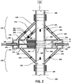
- Figure 2 is a sectional view of Figure 1 showing the HCV 100 in a nominally open position with phantom lines showing the HCV 100 in the closed position.
- the HCV 100 can traverse to a closed position in the event of an open pipeline 105 due to destruction caused by sabotage, fire, natural disasters, or severe weather.
- a pressure sensor and/or a flow sensor (not shown) that monitors pressure and/or flow to create a "signature" in a datastream of the fluid 110 in the pipeline 105.
- the signature (or pressure or flowrate) is then transmitted to a computer (not shown) for analysis, compared to other signatures, depending on the type of fluid 110 that should be in the pipeline 105.
- the computer causes the activation solenoid valve 201 to fully open in the electrical activation channel 150 so that the fluid 110 moves forcefully into the bell reservoir section 130 filling fluid into the needle base chamber 205 and needle base 225 and pushes the needle 230 across the pipeline 105 into the needle seat 245..
- a bell solenoid valve 215 moves from a closed position to an open position allowing fluid 110 to forcefully flow into the bell flow chamber 206 which forces the bell housing 220 across the pipeline 105 and close the HCV 100 .
- the needle base 225 is in close relationship with the bell housing 220 forming a cylinder and piston configuration.
- the needle 230 As the fluid 110 flows into the needle base chamber 205 the needle 230 is urged toward the seat reservoir section 140 perpendicular to and across the pipeline 105. At this point a bell reservoir section shutoff valve 235 residing in the bell relief channel 165 is closed thereby stopping fluid 110 from flowing in the bell relief channel 165 creating a backpressure in the bell reservoir section 130 urging the shutoff bell 240 to move toward the seat reservoir section 140.
- the needle 230 urged by the hydraulic pressure from the bell housing 220 on the needle head 227 contacting and seating on the needle seat 245 located in the seat reservoir section 140.
- the underside of the needle base 225 contacts the base of the shutoff bell 240 and bell housing 220 supplying additional force on the shutoff bell 240 and bell housing 220 to move across the pipeline 105.
- the shutoff bell 240 has closed off the pipeline 105 from any fluid 110 flowing past the shutoff bell 240.
- a hydroelectric pump 250 is used within the hydraulic poppet channel 155 to aid in filling the bell flow chamber 206 with fluid 110.
- a turbine generator 255 is located within the deactivation channel 160. that generates electrical power for operation of instrumentation, operation of the bell reservoir section shutoff valve 235, the seat reservoir relief shutoff valve 260 located in the seat reservoir relief channel 170, and for battery energy (not shown) storage.
- shutoff bell 240 may not have a needle 230 as a guide to move into the seat reservoir section 140 wherein fluid 110 from both the electrical activation channel 150 and the hydraulic poppet channel 155 may both urge the shutoff bell 240 across the pipeline 105.
- Opening the pipeline 105 to resume the flow of fluid 110 proceeds as follows: the bell reservoir section shutoff valve 235 and the deactivation solenoid valve 261 are opened allowing fluid to flow into the output section 125 thereby decreasing the pressure of the fluid 110 in the needle base chamber 205 and bell flow chamber 206 allowing the shutoff bell 240 to move into the bell reservoir section 130.
- the seat reservoir relief shutoff valve 260 remains closed thereby controlling fluid 110 by increasing the pressure in the seat reservoir section 140 and applying pressure on the needle head 227 dislodging it from the needle seat 245 and applying pressure on the shutoff bell 240 such that the bell can traverse across the pipeline 105.
- shutoff bell 240 Once the shutoff bell 240 has moved from being in contact with the seat reservoir section 140, fluid begins to flow from the upper main fluid flow 115 to the lower main fluid flow 116 in the pipeline 105.
- the pressure and/or flow sensors (not shown) are returned to their original states wherein they resume sending information to the computer (not shown) for analysis and the activation solenoid valve 201 and bell solenoid valve 215 are closed, thus stopping the flow of fluid 110 thru the input section 120.
- the seat reservoir relief shutoff valve 260 then opens allowing the flow of fluid 110 to turn the turbine 255 thereby generating electrical power that can be utilized to power the HCV 100 in the event that the HCV is not fully powered via hydraulic means.
- the flow of fluid 110 then passes through the seat reservoir section 140, through the seat reservoir relief channel 170 to the output section 125 of the lower portion of the main pipeline 105.
- an optional worm gear device 290 can be employed which pushes the needle using manual, automatic, or remote control 297 via mechanical or electrical means.
- This device is comprised of a hollow piston shaft 291, a worm gear device 290, manual, automatic, or remote control device 297, and an indented portion 295 to allow for nudging the needle head 227 located in the seat reservoir section 140 and a flat head 296 to allow for nudging the needle base 225 located in the bell reservoir section 130.
- a self cleaning screening mechanism (not shown) which lies in the portholes that provide access entry into the electrical activation channel 150, hydraulic poppet channel 155, and activation channel 160, on either side of the upper main pipeline 105 can be utilized, depending on the cleanliness of the fluid, gas, and/or environmental surroundings.
- Figure 3A illustrates and describes an HCV 100 that uses a ball valve 305 within a pipeline 105 that is attached to and activated by a piston activated HCV 300.
- the ball valve 305 is attached to a lever 310 that rotates the ball valve 305 to open the pipeline 105 or close the pipeline 105 allowing the fluid 110 to flow downstream.
- the fluid flow 115 in Figure 3A is from top to bottom however the pipeline 105 may be rotated so the lever 310 is at any horizontal or vertical position.
- Attached to the inflow section 315 of the pipeline 105 is a piston assembly 320 that is activated by the fluid 110.
- Fluid 110 is allowed to enter the piston assembly 320 via an actuator inflow channel 325 or an actuator outflow channel 330 urging a dual-faced piston 335 in a direction so as to move linkage-1 340 attached to a lever 310 thus moving the ball valve 305.
- Downstream of the ball valve 305 is the outflow section 390 which reconnects to the pipeline 105.
- Figure 3B is a sectional detail of the piston assembly 320 of the HCV 100 described in Figure 3A .
- the piston assembly 320 is in fluid communication with the inflow section 315 (shown in Fig. 3A ) of the pipeline 105 (shown in Fig. 3A ) via the actuator inflow channel 325 and inflow channel valve 345 and actuator outflow channel 330 and outflow channel valve 350.
- the piston assembly 320 houses a dual-faced piston 335 in a fluid chamber 355 wherein the dual-faced piston 335 creates a first fluid chamber 360 and a second fluid chamber 365 that change in volume as the dual-faced piston 335 slides within the fluid chamber 355.
- the first fluid chamber 360 and the second fluid chamber 365 are also connected to an inflow relief channel 370 and an outflow relief channel 375 containing an inflow relief valve 380 and an outflow relief valve 385 respectively.
- the piston assembly 320 moves in one direction when the inflow channel valve 345 is opened and fluid 110 flows into the actuator inflow channel 325 and into the first fluid chamber 360.
- the inflow relief valve 380 is closed thereby capturing the fluid 110 in the first fluid chamber 360.
- the outflow channel valve 350 is also closed and the outflow relief valve 385 is opened. In this manner the fluid 110 flows through the actuator inflow channel 325 and into the first chamber 360 and is restricted from flowing any further by the closed inflow relief valve 380.
- Pressure builds in the first fluid chamber 360 and against a first face 337 of the dual-faced piston 335 urging the dual-faced piston 335 toward the second fluid chamber 365.
- Fluid 110 from the second fluid chamber 365 is urged into the outflow relief channel 375 and past the outflow relief valve 385 and into the outflow section 390 (shown in Fig. 3A ) of the pipeline 105 (shown in Fig. 3A ).
- the linkage-1 340 attached to the dual-faced piston 335 urges the lever 310 (shown in Fig. 3A ) of the ball valve 305 (shown in Fig. 3A ) in a direction to open or close the ball valve 305 (shown in Fig. 3A ) to restrict the pipeline 105 (shown in Fig. 3A ) and stop fluid 110 from flowing.
- the inflow channel valve 345 is closed and the inflow relief valve 380 is opened allowing fluid 110 to flow from the first fluid chamber 360 into the inflow relief channel 370 past the open inflow relief valve 380 to the outflow section 390 (shown in Fig. 3A ) and into the pipeline 105 (shown in Fig. 3A ).
- the outflow channel valve 350 is opened and the outflow relief valve 385 is closed allowing fluid 110 to flow through the actuator outflow channel 330 and into the second fluid chamber 365.
- the fluid 110 exerts a pressure on the second face 338 of the dual-faced piston 335 and urges the dual-faced piston 335 toward the first fluid chamber 360 thus moving the linkage-1 340.
- the linkage-1 340 is attached to the lever 310 (shown in Fig. 3A ) of the ball valve 305 (shown in Fig. 3A ) and the movement of the dual-faced piston 335, linkage-1 340 and the lever 310 (shown in Fig. 3A ) opens the ball valve 305 (shown in Fig. 3A ) within the pipeline 105 (shown in Fig. 3A ) allowing fluid 110 to flow through the pipeline 105 (shown in Fig. 3A ).
- Figure 4 is a schematic of an HCV 100 and isolator pressure assembly 400 using a isolator pressure chamber 405 and a reservoir pressure chamber 410 coupled to a piston assembly 415 which is used to activate and deactivate a ball valve 305 within a pipeline 105.
- an isolator input channel 420 having an isolator input channel valve 425 and attached to an isolator pressure chamber 405. Additionally, there is a reservoir input channel 430 having a reservoir input valve 435 and attached to a reservoir pressure chamber 410. From the isolator pressure chamber 405 is a piston activator channel 440 which is attached to the lower portion of the piston assembly 415 and an isolator relief channel 445 with an isolator relief channel valve 450 wherein the isolator relief channel 445 is attached to the pipeline 105 downstream of the ball valve 305.
- the piston activator channel 440 transmits forced hydraulic fluid 455 (shown in Fig.
- the reservoir piston channel 470 Attached to the reservoir pressure chamber 410 is the reservoir piston channel 470 which attaches to the top portion of the piston assembly 415.
- the isolator pressure chamber 405, piston activator channel 440, piston assembly 415, reservoir piston channel 470 and reservoir pressure chamber 410 form a closed loop for the forced hydraulic fluid 455 (shown in Figure 5 ) keeping the forced hydraulic forced hydraulic fluid 455 (shown in Figure 5 ) and media fluid 110 separate from each other. Further details on the operation will be explained in Figure 5 .
- a reservoir output channel 475 is attached to, and in fluid communication with, the reservoir pressure chamber 410.
- the reservoir output channel 475 also contains the reservoir output channel valve 480 and is attached to the pipeline 105 downstream of the ball valve 305.
- a turbine generator 255 in either the isolator relief channel 445 or the reservoir output channel 475 for generating electricity.
- a hydroelectric pump 250 may be placed within either the isolator input channel 420 or the reservoir input channel 430 to assist the fluid 110 flow into the isolator pressure chamber 405 or the reservoir pressure chamber 410.
- Linkage-1 340 as shown in Figure 3
- linkage-2 465 as shown in Figure 4 may include teeth providing a rack and lever 310 and may also include teeth as a pinion for actuation of the ball valve 305.
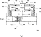
- Figure 5 is a sectional view of the isolator pressure assembly 400 used for actuating and de-actuating an HCV 100 within a pipeline 105.
- isolator input channel valve 425 is open, reservoir input channel valve 435 is closed, isolator relief channel valve 450 is closed and reservoir output channel valve 480 is open, fluid 110 is allowed to flow from the pipeline 105 past the open isolator input channel valve 425 and into the isolator pressure chamber 405.
- Once the fluid fills the first isolator chamber 505 and isolator relief channel 445 up to the isolator relief channel valve 450 it exerts a pressure on the isolator disk 510 and urges the isolator disk 510 to move toward the second isolator chamber 515.
- the second isolator chamber 515 is filled with forced hydraulic fluid 455 which flows from the second isolator chamber 515 into the piston activator channel 440 and into the lower portion of the piston assembly 415.
- the forced hydraulic fluid 455 fills the piston second chamber 520 exerting pressure on the secondary piston face 525 urging the dual-faced piston 460 toward the piston primary chamber 530.
- Forced hydraulic fluid 455 in the piston primary chamber 530 is then urged by the piston primary face 535 to exit the piston primary chamber 530 into the reservoir piston channel 470 and into the reservoir secondary chamber 540 urging the reservoir disk 545 toward the reservoir primary chamber 550.
- the isolator input channel valve 425 is closed, the reservoir input channel valve 435 is opened, the reservoir output channel valve 480 is closed and the isolator relief channel valve 450 is opened.
- Closing the isolator input channel valve 425 restricts fluid 110 from flowing in the isolator input channel 420 while opening the reservoir input channel valve 435 permits fluid 110 to flow into the reservoir pressure chamber 410, more specifically into the reservoir primary chamber 550 up to the closed reservoir output channel valve 480 where the fluid 110 then fills the reservoir primary chamber 550 exerting a force on the reservoir disk 545 and urging it into the reservoir secondary chamber 540.
- the forced hydraulic fluid 455 in the reservoir secondary chamber 540 is pushed out into the reservoir piston channel 470 and into the piston primary chamber 530.
- the pressure of the forced hydraulic fluid 455 on the piston primary face 535 urges the dual-faced piston 460 to move into the piston second chamber 520 thereby moving the linkage-2 465 to move the lever 310 and ball valve 305 to an open position within the pipeline 105.
- the forced hydraulic fluid 455 in the piston second chamber 520 flows out through the piston activator channel 440, into the second isolator chamber 515 creating a pressure on the isolator disk 510 urging the isolator disk 510 to move into the first isolator chamber 505 thereby displacing the fluid 110 out through the isolator relief channel 445, past the isolator relief channel valve 450 and into the pipeline 105 downstream of the ball valve 305.
- Valves 425, 435, 450, and 480 may be manipulated by an operator or computer in a sequence to urge the dual-faced piston 460 in either direction, thereby preventing the flow of fluid 110 in the pipeline 105.
- Figure 6 describes a flow throttling device (FTD) 210 linearly placed within a pipeline 105 that is externally controllable by a computer (not shown) or operator (not shown) and used as an HCV 100 in a pipeline 105.
- a piston assembly 620 that is similar to the one described in Figure 3 is used to create a hydraulic pressure within a piston assembly 620. Fluid 110 is allowed to enter the piston assembly 620 via an actuator inflow channel 625 or an actuator outflow channel 630 urging a dual-faced piston 635 in a direction so as to move fluid into an activation channel 605.
- the piston assembly 620 moves in a downward direction when the inflow channel valve 645 is opened and fluid 110 flows into the actuator inflow channel 625 and into the first fluid chamber 660.
- the inflow relief valve 680 is closed thereby capturing the fluid 110 in the first fluid chamber 660.
- the outflow channel valve 650 and the outflow relief valve 685 are also closed. In this manner the fluid 110 flows through the actuator inflow channel 625 and into the first chamber 660 and is restricted from flowing any further due to the closed inflow relief valve 680.
- Hydraulic pressure builds in the first fluid chamber 660 and against a first face 637 of the dual-faced piston 635 urging the dual-faced piston 635 toward the second fluid chamber 665.
- the hydraulic pressure pushes the fluid 110 from the second fluid chamber 665, such that the fluid exits the piston assembly 620 and subsequently enters an activation channel 605 which is in fluid communication with an FTD bell 610.
- the hydraulic pressure moves the FTD bell 610 into contact with an FTD bell seat 615 thus sealing the FTD 210 preventing fluid 110 to flow within a pipeline 105.
- the fluid 110 exerts hydraulic pressure on the second face 638 of the dual-faced piston 635 and urges the dual-faced piston 635 toward the first fluid chamber 660 thus relieving the pressure in the activation channel 605 thereby allowing the FTD bell 610 to move off the FTD bell seat 615 permitting fluid 110 to flow within the pipeline 105.
- this configuration only electrical activation occurs when using the piston assembly shown for which a dual-faced piston 635 is required.
Landscapes
- Engineering & Computer Science (AREA)
- General Engineering & Computer Science (AREA)
- Mechanical Engineering (AREA)
- Physics & Mathematics (AREA)
- Acoustics & Sound (AREA)
- Fluid-Pressure Circuits (AREA)
- Fluid-Driven Valves (AREA)
Claims (8)
- Soupape de régulation hydroélectrique (100) pour un pipeline de fluide comprenant :quatre sections de tuyau avec une section d'entrée (120) et une section de sortie (125) pouvant toutes deux être rattachées à un canal d'écoulement principal (105) ; ladite section d'entrée (120) étant adaptée à l'écoulement du fluide dans ladite soupape de régulation hydroélectrique (100) et ladite section de sortie (125) étant adaptée à l'écoulement du fluide hors de ladite soupape de régulation hydroélectrique (100) ;une section de réservoir de cloche (130) et une section de réservoir de siège (140) toutes deux dotées d'un bouchon, dans laquelle ladite section de réservoir de cloche (130) et ladite section de réservoir de siège (140) sont alignées entre elles et sont également perpendiculaires à l'écoulement fluide à travers ledit canal d'écoulement principal (105) ;un canal d'activation électrique (150) étant en communication fluide entre ladite section d'entrée (120) et ladite section de réservoir de cloche (130) ;un canal d'évacuation de cloche (165) étant en communication fluide entre ladite section de réservoir de cloche (130) et ladite section de sortie (125) ;un canal de désactivation (160) reliant ladite section d'entrée (120) et ladite section de réservoir de siège (140) ; etun canal d'évacuation de réservoir de siège (170) étant en communication fluide entre ladite section de réservoir de siège (140) et ladite section de sortie (125) ;caractérisée en ce que lesdites quatre sections de tuyau forment un modèle en forme de croix; ladite soupape de régulation hydroélectrique (100) comprenant en outre :un canal de champignon hydraulique (155) étant en communication fluide entre ladite section d'entrée (120) et ladite section de réservoir de cloche (130) ;une pompe en ligne (250) pour assister un écoulement de champignon hydroélectrique à l'intérieur dudit canal de champignon hydraulique (155) ;une aiguille de positionnement (230) ;une cloche (240) peut être poussée par un mouvement maximum de ladite aiguille de positionnement (230) à l'intérieur de ladite cloche (240) de façon à la déplacer en côté à travers ledit canal d'écoulement principal (105) pour ainsi contrôler l'écoulement de fluides à travers ledit canal d'écoulement principal (105).
- Soupape de régulation hydroélectrique selon la revendication 1, dans laquelle à l'intérieur dudit canal d'activation électrique (150) ou dudit canal d'écoulement principal (105) on trouve un capteur de pression et/ou un capteur d'écoulement pour surveiller la pression et/ou l'écoulement créant une signature dans un flux de données dudit fluide à l'intérieur dudit pipeline de fluide.
- Soupape de régulation hydroélectrique selon l'une quelconque des revendications précédentes, comprenant en outre :un système de turbine interne ;un générateur électrique ; etune turbine (255) propulsée par écoulement de fluide dans ledit canal de désactivation (160) en faisant tourner ledit système de turbine interne couplé audit générateur électrique pour ainsi amener du courant électrique aux capteurs internes, aux transducteurs et à la batterie ou aux batteries ; ladite turbine (255) étant positionnée dans ledit canal de désactivation (160) entre ladite section d'admission (120) et ladite section de réservoir de siège (140).
- Soupape de régulation hydroélectrique selon la revendication 3, dans laquelle un dispositif d'étranglement de flux (260) est positionné à l'intérieur dudit canal d'évacuation de réservoir de siège (170) et dans laquelle ladite cloche (240) peut fermer en partie ou entièrement de façon étanche ledit canal d'écoulement principal (105) de telle sorte que ledit dispositif d'étranglement de flux (260) soit adapté soit pour ralentir soit pour arrêter la circulation du fluide dans un canal d'évacuation de réservoir de siège (170) et dans laquelle ledit dispositif d'étranglement de flux (260) revient dans ladite section de réservoir de siège (140) de telle sorte que ladite section de réservoir de siège (140) et ladite section de réservoir de cloche (130) atteignent chacune une stase de pression, maintenant ainsi la position de la cloche (240) à l'intérieur dudit canal d'écoulement principal (105) sans aucune action de pression mécanique ou hydraulique supplémentaire.
- Soupape de régulation hydroélectrique selon l'une quelconque des revendications précédentes, dans laquelle ladite soupape de régulation hydroélectrique (100) est adaptée pour être utilisée dans ledit canal d'écoulement principal (105) pour transporter les fluides ou contrôler l'écoulement fluide, comprenant, mais sans s'y limiter ; le transport de fluide, du gaz, de l'eau, de l'eau salée, une suspension, des eaux usées ou des boissons alcoolisées ou non alcoolisées.
- Soupape de régulation hydroélectrique selon la revendication 3, dans laquelle ladite cloche (240) est adaptée pour commander l'écoulement fluide dans un pipeline de fluide dans lequel ladite cloche (240) est mobile en côté à travers ledit canal d'écoulement principal (105) et dans lequel ledit mouvement latéral de ladite cloche (240) est contraint par une pression hydraulique de fluide provenant de ladite pompe en ligne (250) positionnée à l'intérieur dudit canal de champignon hydraulique (155).
- Soupape de régulation hydroélectrique selon l'une quelconque des revendications précédentes, comprenant en outre des instruments, un ordinateur et une série de soupapes (201, 215, 235, 260, 261), lesdits instruments étant conçus pour détecter un état de volume ou de pression de flux élevé ou bas en cas d'interruption de l'écoulement fluide à l'intérieur dudit canal d'écoulement principal (105), ledit ordinateur activant ladite série de soupapes (201, 215, 235, 260, 261) de façon à bloquer ou encourager l'écoulement fluide à travers le canal d'écoulement principal (105).
- Système comprenant ladite soupape de régulation hydroélectrique (100) selon la revendication 2 ou les alternatives en référence à la revendication 2 dans les revendications 3 à 6 et un ordinateur, ladite soupape de régulation hydroélectrique (100) étant conçue pour transmettre pour analyse ladite signature comprenant la pression ou des données de débit audit ordinateur, ledit ordinateur étant conçu pour comparer ladite signature à d'autres signatures pour déterminer le type de fluide devant être dans ledit canal d'écoulement principal (105) et dans lequel si une signature anormale est détectée, ledit ordinateur est conçu pour déclencher l'ouverture entière d'une électrovanne d'activation (201) dans le canal d'activation électrique (150) pour déplacer entièrement ladite force fluide dans ladite section de réservoir de cloche (130), amenant ainsi le fluide dans une chambre de base d'aiguille (205) à l'intérieur de ladite section de réservoir de cloche (130), ladite chambre de base d'aiguille (205) étant équipée d'une base d'aiguille (225), d'un siège d'aiguille (245) et d'une tête d'aiguille de positionnement (227) pour pousser ladite aiguille (230) à travers ledit canal d'écoulement principal (105) et dans un siège d'aiguille (245) à l'intérieur de ladite section de réservoir de siège (140).
Applications Claiming Priority (1)
| Application Number | Priority Date | Filing Date | Title |
|---|---|---|---|
| PCT/US2011/000614 WO2012138314A1 (fr) | 2011-04-06 | 2011-04-06 | Soupape de régulation hydroélectrique pour emplacements distants |
Publications (3)
| Publication Number | Publication Date |
|---|---|
| EP2694848A1 EP2694848A1 (fr) | 2014-02-12 |
| EP2694848A4 EP2694848A4 (fr) | 2014-09-24 |
| EP2694848B1 true EP2694848B1 (fr) | 2020-03-11 |
Family
ID=46969460
Family Applications (1)
| Application Number | Title | Priority Date | Filing Date |
|---|---|---|---|
| EP11862941.9A Active EP2694848B1 (fr) | 2011-04-06 | 2011-04-06 | Soupape de régulation hydroélectrique pour emplacements distants |
Country Status (3)
| Country | Link |
|---|---|
| US (3) | US9581267B2 (fr) |
| EP (1) | EP2694848B1 (fr) |
| WO (1) | WO2012138314A1 (fr) |
Families Citing this family (6)
| Publication number | Priority date | Publication date | Assignee | Title |
|---|---|---|---|---|
| US9347304B2 (en) * | 2011-08-29 | 2016-05-24 | Exxonmobil Upstream Research Company | System and method for high speed hydraulic actuation |
| EP3537160B1 (fr) * | 2015-03-23 | 2020-08-12 | Roche Diagnostics GmbH | Système de distribution d'échantillons de laboratoire et système d'automatisation de laboratoire |
| BR112017020887B1 (pt) | 2015-04-30 | 2022-06-14 | Halliburton Energy Services, Inc | Método de controle de fundo de poço e aparelho de completação de fundo de poço |
| WO2016175827A1 (fr) * | 2015-04-30 | 2016-11-03 | Halliburton Energy Services, Inc. | Ensemble de complétion intelligent en tubage |
| CN107020051A (zh) * | 2016-02-02 | 2017-08-08 | 王成芝 | 液体比例加药器 |
| CN114198591A (zh) * | 2021-11-17 | 2022-03-18 | 安徽山水空间装饰有限责任公司 | 一种方便室内下水管检修的包管结构及施工工艺 |
Family Cites Families (116)
| Publication number | Priority date | Publication date | Assignee | Title |
|---|---|---|---|---|
| US2352883A (en) | 1940-04-12 | 1944-07-04 | Nat Lead Co | Production and purification of fatty oils |
| US3790124A (en) | 1972-10-03 | 1974-02-05 | J Ellett | Toggle linkage valve actuator |
| US3838711A (en) | 1973-03-19 | 1974-10-01 | Bralorne Res Ltd | Three-way pilot valve |
| US3958217A (en) | 1974-05-10 | 1976-05-18 | Teleco Inc. | Pilot operated mud-pulse valve |
| CA1031311A (fr) | 1975-09-02 | 1978-05-16 | James R. Ellett | Dispositif d'arret en situation d'urgence |
| US4348058A (en) | 1980-04-01 | 1982-09-07 | Slurry Mining Engineering Inc. | Method and apparatus for slurry borehole mining |
| US4379543A (en) | 1980-08-05 | 1983-04-12 | Valinco, Inc. | Vane type valve actuator |
| CA1155683A (fr) | 1980-12-16 | 1983-10-25 | Bralorne Resources Limited A/T/A Engineered Oil Controls | Echantillonneuse |
| US4384569A (en) | 1981-02-24 | 1983-05-24 | Clearman Francis R | Solar energy collector/storage system |
| CA1217759A (fr) | 1983-07-08 | 1987-02-10 | Intech Oil Tools Ltd. | Materiel de forage |
| US4589493A (en) | 1984-04-02 | 1986-05-20 | Cameron Iron Works, Inc. | Subsea wellhead production apparatus with a retrievable subsea choke |
| GB2157345A (en) | 1984-04-12 | 1985-10-23 | Dies Downhole Drilling Inc | Mud pulse telemetry tool |
| DE3434014A1 (de) | 1984-09-15 | 1986-03-20 | Beringer-Hydraulik GmbH, Neuheim, Zug | Hydraulische steuerung |
| US4611630A (en) | 1984-12-06 | 1986-09-16 | Hydril Company | Single hydraulic line choke valve system |
| US4825421A (en) | 1986-05-19 | 1989-04-25 | Jeter John D | Signal pressure pulse generator |
| US4817739A (en) | 1986-06-23 | 1989-04-04 | Jeter John D | Drilling enhancement tool |
| US4742498A (en) | 1986-10-08 | 1988-05-03 | Eastman Christensen Company | Pilot operated mud pulse valve and method of operating the same |
| JPH0353078Y2 (fr) | 1986-12-13 | 1991-11-19 | ||
| US5070900A (en) | 1988-02-08 | 1991-12-10 | Bralorne Resources Limited | Safety valve actuator assembly |
| US5291918A (en) | 1987-04-28 | 1994-03-08 | Barber Industries Ltd. | Safety valve actuator assembly |
| DE3715512C1 (fr) | 1987-05-09 | 1988-10-27 | Eastman Christensen Co., Salt Lake City, Utah, Us | |
| DE3715514C1 (fr) | 1987-05-09 | 1988-09-08 | Eastman Christensen Co., Salt Lake City, Utah, Us | |
| US4825895A (en) | 1987-06-16 | 1989-05-02 | Chevron Research Company | Water injection choke valve |
| US4848473A (en) | 1987-12-21 | 1989-07-18 | Chevron Research Company | Subsea well choke system |
| US4961560A (en) | 1988-03-18 | 1990-10-09 | Bralorne Resources Limited | Two way latching trip valve |
| US5081419A (en) | 1990-10-09 | 1992-01-14 | Baker Hughes Incorporated | High sensitivity well logging system having dual transmitter antennas and intermediate series resonant |
| US4869100A (en) | 1988-07-22 | 1989-09-26 | Birdwell J C | Variable orifice control means |
| US5190114A (en) | 1988-11-25 | 1993-03-02 | Intech International Inc. | Flow pulsing apparatus for drill string |
| US5009272A (en) | 1988-11-25 | 1991-04-23 | Intech International, Inc. | Flow pulsing method and apparatus for drill string |
| DE3926908C1 (fr) | 1989-08-16 | 1990-10-11 | Eastman Christensen Co., Salt Lake City, Utah, Us | |
| US5117398A (en) | 1990-04-11 | 1992-05-26 | Jeter John D | Well communication pulser |
| US5103430A (en) | 1990-11-01 | 1992-04-07 | The Bob Fournet Company | Mud pulse pressure signal generator |
| US5134285A (en) | 1991-01-15 | 1992-07-28 | Teleco Oilfield Services Inc. | Formation density logging mwd apparatus |
| US5250806A (en) | 1991-03-18 | 1993-10-05 | Schlumberger Technology Corporation | Stand-off compensated formation measurements apparatus and method |
| US5205361A (en) | 1991-04-30 | 1993-04-27 | Completion Services, Inc. | Up and down travelling disc valve assembly apparatus |
| US5215113A (en) | 1991-06-20 | 1993-06-01 | Terry Paul E | Precision safety shut-off valve |
| US5213133A (en) | 1991-10-04 | 1993-05-25 | Barber Industries Ltd. | Pressure responsive pilot control valve |
| NO306522B1 (no) | 1992-01-21 | 1999-11-15 | Anadrill Int Sa | Fremgangsmaate for akustisk overföring av maalesignaler ved maaling under boring |
| US5508975A (en) | 1992-08-25 | 1996-04-16 | Industrial Sound Technologies, Inc. | Apparatus for degassing liquids |
| US5626016A (en) | 1992-08-25 | 1997-05-06 | Ind Sound Technologies Inc | Water hammer driven vibrator having deformable vibrating elements |
| US5395090A (en) | 1992-10-23 | 1995-03-07 | Rosaen; Nils O. | Valve for high pressure fluid systems |
| CA2088185C (fr) | 1993-02-05 | 1999-08-31 | Clarence William Johnson | Vanne pilote a deux circuits |
| US5473579A (en) | 1993-10-25 | 1995-12-05 | Ronald L. Shaw | Well bore communication pulser |
| US5438170A (en) | 1994-04-28 | 1995-08-01 | Klaveness; Alf | Borehole seismic pulse generator and system |
| US5517464A (en) | 1994-05-04 | 1996-05-14 | Schlumberger Technology Corporation | Integrated modulator and turbine-generator for a measurement while drilling tool |
| US5461230A (en) | 1994-08-16 | 1995-10-24 | Halliburton Company | Method and apparatus for temperature compensation of gamma tools in MWD environments |
| US5804820A (en) | 1994-09-16 | 1998-09-08 | Schlumberger Technology Corporation | Method for determining density of an earth formation |
| US5539225A (en) | 1994-09-16 | 1996-07-23 | Schlumberger Technology Corporation | Accelerator-based methods and apparatus for measurement-while-drilling |
| US6016288A (en) | 1994-12-05 | 2000-01-18 | Thomas Tools, Inc. | Servo-driven mud pulser |
| US5540295A (en) | 1995-03-27 | 1996-07-30 | Serrette; Billy J. | Vibrator for drill stems |
| US5802011A (en) | 1995-10-04 | 1998-09-01 | Amoco Corporation | Pressure signalling for fluidic media |
| US5901113A (en) | 1996-03-12 | 1999-05-04 | Schlumberger Technology Corporation | Inverse vertical seismic profiling using a measurement while drilling tool as a seismic source |
| US7032689B2 (en) | 1996-03-25 | 2006-04-25 | Halliburton Energy Services, Inc. | Method and system for predicting performance of a drilling system of a given formation |
| CA2175296A1 (fr) | 1996-04-29 | 1997-10-30 | Bruno H. Walter | Methode et appareil creant un debit pulse augmentant la vitesse de forage |
| US6279670B1 (en) | 1996-05-18 | 2001-08-28 | Andergauge Limited | Downhole flow pulsing apparatus |
| US6003620A (en) | 1996-07-26 | 1999-12-21 | Advanced Coring Technology, Inc. | Downhole in-situ measurement of physical and or chemical properties including fluid saturations of cores while coring |
| US5836353A (en) | 1996-09-11 | 1998-11-17 | Scientific Drilling International, Inc. | Valve assembly for borehole telemetry in drilling fluid |
| US6002643A (en) | 1997-08-19 | 1999-12-14 | Computalog Limited | Pulser |
| US6102138A (en) | 1997-08-20 | 2000-08-15 | Baker Hughes Incorporated | Pressure-modulation valve assembly |
| US6057784A (en) | 1997-09-02 | 2000-05-02 | Schlumberger Technology Corporatioin | Apparatus and system for making at-bit measurements while drilling |
| US6237701B1 (en) | 1997-11-17 | 2001-05-29 | Tempress Technologies, Inc. | Impulsive suction pulse generator for borehole |
| US6244561B1 (en) * | 1998-01-09 | 2001-06-12 | Hansen Technologies Corporation | Modulating expansion valve |
| US6268726B1 (en) | 1998-01-16 | 2001-07-31 | Numar Corporation | Method and apparatus for nuclear magnetic resonance measuring while drilling |
| US6481689B2 (en) | 1998-02-09 | 2002-11-19 | Sturman Bg, Llc | Balanced fluid control valve |
| US6247542B1 (en) | 1998-03-06 | 2001-06-19 | Baker Hughes Incorporated | Non-rotating sensor assembly for measurement-while-drilling applications |
| NO306418B1 (no) | 1998-03-23 | 1999-11-01 | Rogalandsforskning | Utblaasningssikring |
| US6082473A (en) | 1998-05-22 | 2000-07-04 | Dickey; Winton B. | Drill bit including non-plugging nozzle and method for removing cuttings from drilling tool |
| US6119557A (en) | 1998-08-24 | 2000-09-19 | Bilco Tools, Inc. | Power tong with shutdown system and method |
| US6338390B1 (en) | 1999-01-12 | 2002-01-15 | Baker Hughes Incorporated | Method and apparatus for drilling a subterranean formation employing drill bit oscillation |
| US6300624B1 (en) | 1999-03-25 | 2001-10-09 | Halliburton Energy Services, Inc. | Radiation detector |
| US6276135B1 (en) | 1999-04-29 | 2001-08-21 | Argus Machine Co. Ltd. | Self-contained hydraulic ESD system |
| US6469637B1 (en) | 1999-08-12 | 2002-10-22 | Baker Hughes Incorporated | Adjustable shear valve mud pulser and controls therefor |
| DE10037530A1 (de) | 1999-08-31 | 2001-03-22 | Ntn Toyo Bearing Co Ltd | Dichtungsvorrichtung für Lager |
| US6659200B1 (en) | 1999-12-20 | 2003-12-09 | Halliburton Energy Services, Inc. | Actuator assembly and method for actuating downhole assembly |
| KR20010108252A (ko) | 1999-12-24 | 2001-12-07 | 다니구찌 이찌로오, 기타오카 다카시 | 배기가스 재순환 밸브장치 |
| DE10000901A1 (de) * | 2000-01-12 | 2001-07-19 | Mannesmann Sachs Ag | System und Verfahren zum Einregeln eines Kolbens in einem Zylinder |
| US6763902B2 (en) | 2000-04-12 | 2004-07-20 | Smith International, Inc. | Rockbit with attachable device for improved cone cleaning |
| GB0009848D0 (en) | 2000-04-25 | 2000-06-07 | Tulloch David W | Apparatus and method of use in drilling of well bores |
| GB0015497D0 (en) | 2000-06-23 | 2000-08-16 | Andergauge Ltd | Drilling method |
| US6772783B2 (en) | 2000-07-10 | 2004-08-10 | Reggie H. Etheridge | Rotary to linear valve and method of use |
| US6714138B1 (en) | 2000-09-29 | 2004-03-30 | Aps Technology, Inc. | Method and apparatus for transmitting information to the surface from a drill string down hole in a well |
| US6626253B2 (en) | 2001-02-27 | 2003-09-30 | Baker Hughes Incorporated | Oscillating shear valve for mud pulse telemetry |
| US6898150B2 (en) | 2001-03-13 | 2005-05-24 | Baker Hughes Incorporated | Hydraulically balanced reciprocating pulser valve for mud pulse telemetry |
| CA2372760C (fr) | 2002-02-20 | 2010-01-05 | Argus Machine Co. Ltd. | Systeme d'arret d'urgence hydraulique autonome |
| US6668948B2 (en) | 2002-04-10 | 2003-12-30 | Buckman Jet Drilling, Inc. | Nozzle for jet drilling and associated method |
| US20040108138A1 (en) | 2002-08-21 | 2004-06-10 | Iain Cooper | Hydraulic Optimization of Drilling Fluids in Borehole Drilling |
| US6840337B2 (en) | 2002-08-28 | 2005-01-11 | Halliburton Energy Services, Inc. | Method and apparatus for removing cuttings |
| US7471024B2 (en) | 2002-09-20 | 2008-12-30 | Man-suk Park | Apparatus for power transmission by magnetic force and method thereof |
| US7063174B2 (en) | 2002-11-12 | 2006-06-20 | Baker Hughes Incorporated | Method for reservoir navigation using formation pressure testing measurement while drilling |
| US6970398B2 (en) | 2003-02-07 | 2005-11-29 | Schlumberger Technology Corporation | Pressure pulse generator for downhole tool |
| US7011156B2 (en) | 2003-02-19 | 2006-03-14 | Ashmin, Lc | Percussion tool and method |
| US6997272B2 (en) | 2003-04-02 | 2006-02-14 | Halliburton Energy Services, Inc. | Method and apparatus for increasing drilling capacity and removing cuttings when drilling with coiled tubing |
| GB2401164B (en) * | 2003-04-29 | 2006-01-18 | Abb Offshore Systems Ltd | Pipeline protection system |
| US7655010B2 (en) | 2003-09-30 | 2010-02-02 | Depuy Spine, Inc. | Vertebral fusion device and method for using same |
| US7213661B2 (en) | 2003-12-05 | 2007-05-08 | Smith International, Inc. | Dual property hydraulic configuration |
| US7051821B2 (en) | 2003-12-18 | 2006-05-30 | Halliburton | Adjustable hole cleaning device |
| US7100708B2 (en) | 2003-12-23 | 2006-09-05 | Varco I/P, Inc. | Autodriller bit protection system and method |
| US6998724B2 (en) | 2004-02-18 | 2006-02-14 | Fmc Technologies, Inc. | Power generation system |
| JP4160530B2 (ja) * | 2004-04-28 | 2008-10-01 | 日立建機株式会社 | 制御弁装置及び圧力回路 |
| US7180826B2 (en) | 2004-10-01 | 2007-02-20 | Teledrill Inc. | Measurement while drilling bi-directional pulser operating in a near laminar annular flow channel |
| GB2419202B (en) | 2004-10-12 | 2006-10-25 | Smith International | A method of manufacturing a drill bit and a drill bit |
| DK1853840T3 (da) * | 2005-03-04 | 2011-03-28 | Parker Hannifin Corp | To-positions pilotstyret ventilaggregat |
| US7319638B2 (en) | 2005-09-06 | 2008-01-15 | Collette Herman D | Hydraulic oscillator for use in a transmitter valve |
| US7145834B1 (en) | 2006-02-14 | 2006-12-05 | Jeter John D | Well bore communication pulser |
| GB2437306B (en) * | 2006-04-22 | 2010-07-07 | Sam Mather | Autonomous shut-off valve system |
| US8138943B2 (en) | 2007-01-25 | 2012-03-20 | David John Kusko | Measurement while drilling pulser with turbine power generation unit |
| US7958952B2 (en) | 2007-05-03 | 2011-06-14 | Teledrill Inc. | Pulse rate of penetration enhancement device and method |
| US7836948B2 (en) | 2007-05-03 | 2010-11-23 | Teledrill Inc. | Flow hydraulic amplification for a pulsing, fracturing, and drilling (PFD) device |
| US20090114396A1 (en) | 2007-11-05 | 2009-05-07 | David John Kusko | Wellsite measurement and control while producing device |
| DE102008011982A1 (de) | 2008-02-29 | 2009-09-03 | Honeywell Technologies Sarl | Ventilanordnung mit Steuerventilen und einem von diesen stufenlos gesteuerten Hauptventil |
| US7673705B2 (en) | 2008-06-06 | 2010-03-09 | The Gearhart Companies, Inc. | Compartmentalized MWD tool with isolated pressure compensator |
| MX2011006666A (es) | 2008-12-17 | 2011-09-06 | Gabor Vecseri | Sistema de sellado de alta presion de respuesta rapida para dispositivos moduladores de flujo. |
| US8720572B2 (en) | 2008-12-17 | 2014-05-13 | Teledrill, Inc. | High pressure fast response sealing system for flow modulating devices |
| US8286661B2 (en) * | 2009-05-26 | 2012-10-16 | Honeywell International Inc. | Bi-directional overpressure shut-off valve |
| DE102011101187B4 (de) * | 2011-05-11 | 2014-09-04 | Magna Steyr Fahrzeugtechnik Ag & Co Kg | Druckminderer |
| US9080687B2 (en) * | 2012-05-24 | 2015-07-14 | Honeywell International Inc. | Pressure and flow altitude compensated shutoff valve |
-
2011
- 2011-04-06 EP EP11862941.9A patent/EP2694848B1/fr active Active
- 2011-04-06 US US14/110,325 patent/US9581267B2/en active Active
- 2011-04-06 WO PCT/US2011/000614 patent/WO2012138314A1/fr active Application Filing
-
2017
- 2017-01-17 US US15/407,792 patent/US9920886B2/en active Active
-
2018
- 2018-02-06 US US15/889,554 patent/US20180274732A1/en not_active Abandoned
Non-Patent Citations (1)
| Title |
|---|
| None * |
Also Published As
| Publication number | Publication date |
|---|---|
| US9581267B2 (en) | 2017-02-28 |
| WO2012138314A1 (fr) | 2012-10-11 |
| US20180274732A1 (en) | 2018-09-27 |
| US9920886B2 (en) | 2018-03-20 |
| US20140090734A1 (en) | 2014-04-03 |
| EP2694848A1 (fr) | 2014-02-12 |
| EP2694848A4 (fr) | 2014-09-24 |
| US20170152995A1 (en) | 2017-06-01 |
Similar Documents
| Publication | Publication Date | Title |
|---|---|---|
| US9920886B2 (en) | Hydroelectric control valve for remote locations | |
| RU2448237C2 (ru) | Подводное устройство для приведения в действие подводного оборудования | |
| US20090114396A1 (en) | Wellsite measurement and control while producing device | |
| US8453749B2 (en) | Control system for an annulus balanced subsurface safety valve | |
| US10808483B2 (en) | System for hydrocarbon recovery | |
| NO340285B1 (no) | Fremgangsmåte omfattende en gassløfteventil for å styre fluid kommunikasjon i en brønn | |
| NO324442B1 (no) | Styringssystem for kjemisk injisering samt fremgangsmate for kjemisk injisering i flere bronner | |
| AU2012343914B2 (en) | Annular barrier system with flow lines | |
| NO344230B1 (no) | Brønnverktøy innbefattende en aktuator for forflytning av et aktuatorelement. | |
| US11293265B2 (en) | Tubing pressure insensitive failsafe wireline retrievable safety valve | |
| NO345315B1 (no) | Utløsersystem og fremgangsmåte som ikke påvirkes av rørtrykket | |
| MX2007007451A (es) | Metodo y aparato para derivacion fluida de una herramienta de pozo. | |
| EP2203628B1 (fr) | Soupape ouverte par cisaillement | |
| EP2834445B1 (fr) | Actionneur pour soupape de double train de tiges et configurations de soupape de train de tiges pour celui-ci | |
| EP3287590B1 (fr) | Système de valve à sécurité intégrée | |
| US20160102519A1 (en) | Emergency valve assembly for extraction wells, well equipped with said valve and process for managing an extraction well with said valve under emergency conditions | |
| US8978757B2 (en) | Remote actuation testing tool for high pressure differential downhole environments | |
| CN104695902A (zh) | 液压冲洗系统 | |
| US8281897B1 (en) | Automatic accumulator switching apparatus and system | |
| US20240141751A1 (en) | Downhole tool including a valve having a modular activation system |
Legal Events
| Date | Code | Title | Description |
|---|---|---|---|
| PUAI | Public reference made under article 153(3) epc to a published international application that has entered the european phase |
Free format text: ORIGINAL CODE: 0009012 |
|
| 17P | Request for examination filed |
Effective date: 20131106 |
|
| AK | Designated contracting states |
Kind code of ref document: A1 Designated state(s): AL AT BE BG CH CY CZ DE DK EE ES FI FR GB GR HR HU IE IS IT LI LT LU LV MC MK MT NL NO PL PT RO RS SE SI SK SM TR |
|
| DAX | Request for extension of the european patent (deleted) | ||
| A4 | Supplementary search report drawn up and despatched |
Effective date: 20140825 |
|
| RIC1 | Information provided on ipc code assigned before grant |
Ipc: F16K 37/00 20060101ALI20140819BHEP Ipc: F16D 31/02 20060101ALI20140819BHEP Ipc: F16K 31/66 20060101ALI20140819BHEP Ipc: F16K 3/24 20060101AFI20140819BHEP Ipc: F16K 31/44 20060101ALI20140819BHEP |
|
| 17Q | First examination report despatched |
Effective date: 20160826 |
|
| STAA | Information on the status of an ep patent application or granted ep patent |
Free format text: STATUS: EXAMINATION IS IN PROGRESS |
|
| GRAP | Despatch of communication of intention to grant a patent |
Free format text: ORIGINAL CODE: EPIDOSNIGR1 |
|
| STAA | Information on the status of an ep patent application or granted ep patent |
Free format text: STATUS: GRANT OF PATENT IS INTENDED |
|
| INTG | Intention to grant announced |
Effective date: 20190906 |
|
| GRAJ | Information related to disapproval of communication of intention to grant by the applicant or resumption of examination proceedings by the epo deleted |
Free format text: ORIGINAL CODE: EPIDOSDIGR1 |
|
| GRAS | Grant fee paid |
Free format text: ORIGINAL CODE: EPIDOSNIGR3 |
|
| GRAJ | Information related to disapproval of communication of intention to grant by the applicant or resumption of examination proceedings by the epo deleted |
Free format text: ORIGINAL CODE: EPIDOSDIGR1 |
|
| GRAL | Information related to payment of fee for publishing/printing deleted |
Free format text: ORIGINAL CODE: EPIDOSDIGR3 |
|
| STAA | Information on the status of an ep patent application or granted ep patent |
Free format text: STATUS: EXAMINATION IS IN PROGRESS |
|
| GRAR | Information related to intention to grant a patent recorded |
Free format text: ORIGINAL CODE: EPIDOSNIGR71 |
|
| STAA | Information on the status of an ep patent application or granted ep patent |
Free format text: STATUS: GRANT OF PATENT IS INTENDED |
|
| GRAA | (expected) grant |
Free format text: ORIGINAL CODE: 0009210 |
|
| STAA | Information on the status of an ep patent application or granted ep patent |
Free format text: STATUS: THE PATENT HAS BEEN GRANTED |
|
| INTG | Intention to grant announced |
Effective date: 20190906 |
|
| INTG | Intention to grant announced |
Effective date: 20200122 |
|
| AK | Designated contracting states |
Kind code of ref document: B1 Designated state(s): AL AT BE BG CH CY CZ DE DK EE ES FI FR GB GR HR HU IE IS IT LI LT LU LV MC MK MT NL NO PL PT RO RS SE SI SK SM TR |
|
| REG | Reference to a national code |
Ref country code: GB Ref legal event code: FG4D |
|
| REG | Reference to a national code |
Ref country code: CH Ref legal event code: EP |
|
| REG | Reference to a national code |
Ref country code: AT Ref legal event code: REF Ref document number: 1243521 Country of ref document: AT Kind code of ref document: T Effective date: 20200315 |
|
| REG | Reference to a national code |
Ref country code: DE Ref legal event code: R096 Ref document number: 602011065592 Country of ref document: DE |
|
| REG | Reference to a national code |
Ref country code: IE Ref legal event code: FG4D |
|
| PG25 | Lapsed in a contracting state [announced via postgrant information from national office to epo] |
Ref country code: NO Free format text: LAPSE BECAUSE OF FAILURE TO SUBMIT A TRANSLATION OF THE DESCRIPTION OR TO PAY THE FEE WITHIN THE PRESCRIBED TIME-LIMIT Effective date: 20200611 Ref country code: FI Free format text: LAPSE BECAUSE OF FAILURE TO SUBMIT A TRANSLATION OF THE DESCRIPTION OR TO PAY THE FEE WITHIN THE PRESCRIBED TIME-LIMIT Effective date: 20200311 Ref country code: RS Free format text: LAPSE BECAUSE OF FAILURE TO SUBMIT A TRANSLATION OF THE DESCRIPTION OR TO PAY THE FEE WITHIN THE PRESCRIBED TIME-LIMIT Effective date: 20200311 |
|
| REG | Reference to a national code |
Ref country code: NL Ref legal event code: MP Effective date: 20200311 |
|
| PG25 | Lapsed in a contracting state [announced via postgrant information from national office to epo] |
Ref country code: GR Free format text: LAPSE BECAUSE OF FAILURE TO SUBMIT A TRANSLATION OF THE DESCRIPTION OR TO PAY THE FEE WITHIN THE PRESCRIBED TIME-LIMIT Effective date: 20200612 Ref country code: HR Free format text: LAPSE BECAUSE OF FAILURE TO SUBMIT A TRANSLATION OF THE DESCRIPTION OR TO PAY THE FEE WITHIN THE PRESCRIBED TIME-LIMIT Effective date: 20200311 Ref country code: BG Free format text: LAPSE BECAUSE OF FAILURE TO SUBMIT A TRANSLATION OF THE DESCRIPTION OR TO PAY THE FEE WITHIN THE PRESCRIBED TIME-LIMIT Effective date: 20200611 Ref country code: SE Free format text: LAPSE BECAUSE OF FAILURE TO SUBMIT A TRANSLATION OF THE DESCRIPTION OR TO PAY THE FEE WITHIN THE PRESCRIBED TIME-LIMIT Effective date: 20200311 Ref country code: LV Free format text: LAPSE BECAUSE OF FAILURE TO SUBMIT A TRANSLATION OF THE DESCRIPTION OR TO PAY THE FEE WITHIN THE PRESCRIBED TIME-LIMIT Effective date: 20200311 |
|
| REG | Reference to a national code |
Ref country code: LT Ref legal event code: MG4D |
|
| PG25 | Lapsed in a contracting state [announced via postgrant information from national office to epo] |
Ref country code: NL Free format text: LAPSE BECAUSE OF FAILURE TO SUBMIT A TRANSLATION OF THE DESCRIPTION OR TO PAY THE FEE WITHIN THE PRESCRIBED TIME-LIMIT Effective date: 20200311 |
|
| PG25 | Lapsed in a contracting state [announced via postgrant information from national office to epo] |
Ref country code: LT Free format text: LAPSE BECAUSE OF FAILURE TO SUBMIT A TRANSLATION OF THE DESCRIPTION OR TO PAY THE FEE WITHIN THE PRESCRIBED TIME-LIMIT Effective date: 20200311 Ref country code: EE Free format text: LAPSE BECAUSE OF FAILURE TO SUBMIT A TRANSLATION OF THE DESCRIPTION OR TO PAY THE FEE WITHIN THE PRESCRIBED TIME-LIMIT Effective date: 20200311 Ref country code: SM Free format text: LAPSE BECAUSE OF FAILURE TO SUBMIT A TRANSLATION OF THE DESCRIPTION OR TO PAY THE FEE WITHIN THE PRESCRIBED TIME-LIMIT Effective date: 20200311 Ref country code: CZ Free format text: LAPSE BECAUSE OF FAILURE TO SUBMIT A TRANSLATION OF THE DESCRIPTION OR TO PAY THE FEE WITHIN THE PRESCRIBED TIME-LIMIT Effective date: 20200311 Ref country code: IS Free format text: LAPSE BECAUSE OF FAILURE TO SUBMIT A TRANSLATION OF THE DESCRIPTION OR TO PAY THE FEE WITHIN THE PRESCRIBED TIME-LIMIT Effective date: 20200711 Ref country code: RO Free format text: LAPSE BECAUSE OF FAILURE TO SUBMIT A TRANSLATION OF THE DESCRIPTION OR TO PAY THE FEE WITHIN THE PRESCRIBED TIME-LIMIT Effective date: 20200311 Ref country code: SK Free format text: LAPSE BECAUSE OF FAILURE TO SUBMIT A TRANSLATION OF THE DESCRIPTION OR TO PAY THE FEE WITHIN THE PRESCRIBED TIME-LIMIT Effective date: 20200311 Ref country code: PT Free format text: LAPSE BECAUSE OF FAILURE TO SUBMIT A TRANSLATION OF THE DESCRIPTION OR TO PAY THE FEE WITHIN THE PRESCRIBED TIME-LIMIT Effective date: 20200805 |
|
| REG | Reference to a national code |
Ref country code: AT Ref legal event code: MK05 Ref document number: 1243521 Country of ref document: AT Kind code of ref document: T Effective date: 20200311 |
|
| REG | Reference to a national code |
Ref country code: CH Ref legal event code: PL |
|
| REG | Reference to a national code |
Ref country code: DE Ref legal event code: R097 Ref document number: 602011065592 Country of ref document: DE |
|
| PG25 | Lapsed in a contracting state [announced via postgrant information from national office to epo] |
Ref country code: MC Free format text: LAPSE BECAUSE OF FAILURE TO SUBMIT A TRANSLATION OF THE DESCRIPTION OR TO PAY THE FEE WITHIN THE PRESCRIBED TIME-LIMIT Effective date: 20200311 |
|
| PLBE | No opposition filed within time limit |
Free format text: ORIGINAL CODE: 0009261 |
|
| STAA | Information on the status of an ep patent application or granted ep patent |
Free format text: STATUS: NO OPPOSITION FILED WITHIN TIME LIMIT |
|
| PG25 | Lapsed in a contracting state [announced via postgrant information from national office to epo] |
Ref country code: IT Free format text: LAPSE BECAUSE OF FAILURE TO SUBMIT A TRANSLATION OF THE DESCRIPTION OR TO PAY THE FEE WITHIN THE PRESCRIBED TIME-LIMIT Effective date: 20200311 Ref country code: ES Free format text: LAPSE BECAUSE OF FAILURE TO SUBMIT A TRANSLATION OF THE DESCRIPTION OR TO PAY THE FEE WITHIN THE PRESCRIBED TIME-LIMIT Effective date: 20200311 Ref country code: LU Free format text: LAPSE BECAUSE OF NON-PAYMENT OF DUE FEES Effective date: 20200406 Ref country code: AT Free format text: LAPSE BECAUSE OF FAILURE TO SUBMIT A TRANSLATION OF THE DESCRIPTION OR TO PAY THE FEE WITHIN THE PRESCRIBED TIME-LIMIT Effective date: 20200311 Ref country code: DK Free format text: LAPSE BECAUSE OF FAILURE TO SUBMIT A TRANSLATION OF THE DESCRIPTION OR TO PAY THE FEE WITHIN THE PRESCRIBED TIME-LIMIT Effective date: 20200311 Ref country code: CH Free format text: LAPSE BECAUSE OF NON-PAYMENT OF DUE FEES Effective date: 20200430 Ref country code: LI Free format text: LAPSE BECAUSE OF NON-PAYMENT OF DUE FEES Effective date: 20200430 |
|
| REG | Reference to a national code |
Ref country code: BE Ref legal event code: MM Effective date: 20200430 |
|
| 26N | No opposition filed |
Effective date: 20201214 |
|
| PG25 | Lapsed in a contracting state [announced via postgrant information from national office to epo] |
Ref country code: BE Free format text: LAPSE BECAUSE OF NON-PAYMENT OF DUE FEES Effective date: 20200430 Ref country code: PL Free format text: LAPSE BECAUSE OF FAILURE TO SUBMIT A TRANSLATION OF THE DESCRIPTION OR TO PAY THE FEE WITHIN THE PRESCRIBED TIME-LIMIT Effective date: 20200311 Ref country code: SI Free format text: LAPSE BECAUSE OF FAILURE TO SUBMIT A TRANSLATION OF THE DESCRIPTION OR TO PAY THE FEE WITHIN THE PRESCRIBED TIME-LIMIT Effective date: 20200311 |
|
| PG25 | Lapsed in a contracting state [announced via postgrant information from national office to epo] |
Ref country code: IE Free format text: LAPSE BECAUSE OF NON-PAYMENT OF DUE FEES Effective date: 20200406 |
|
| PG25 | Lapsed in a contracting state [announced via postgrant information from national office to epo] |
Ref country code: TR Free format text: LAPSE BECAUSE OF FAILURE TO SUBMIT A TRANSLATION OF THE DESCRIPTION OR TO PAY THE FEE WITHIN THE PRESCRIBED TIME-LIMIT Effective date: 20200311 Ref country code: MT Free format text: LAPSE BECAUSE OF FAILURE TO SUBMIT A TRANSLATION OF THE DESCRIPTION OR TO PAY THE FEE WITHIN THE PRESCRIBED TIME-LIMIT Effective date: 20200311 Ref country code: CY Free format text: LAPSE BECAUSE OF FAILURE TO SUBMIT A TRANSLATION OF THE DESCRIPTION OR TO PAY THE FEE WITHIN THE PRESCRIBED TIME-LIMIT Effective date: 20200311 |
|
| PG25 | Lapsed in a contracting state [announced via postgrant information from national office to epo] |
Ref country code: MK Free format text: LAPSE BECAUSE OF FAILURE TO SUBMIT A TRANSLATION OF THE DESCRIPTION OR TO PAY THE FEE WITHIN THE PRESCRIBED TIME-LIMIT Effective date: 20200311 Ref country code: AL Free format text: LAPSE BECAUSE OF FAILURE TO SUBMIT A TRANSLATION OF THE DESCRIPTION OR TO PAY THE FEE WITHIN THE PRESCRIBED TIME-LIMIT Effective date: 20200311 |
|
| PGFP | Annual fee paid to national office [announced via postgrant information from national office to epo] |
Ref country code: GB Payment date: 20240213 Year of fee payment: 14 |
|
| PGFP | Annual fee paid to national office [announced via postgrant information from national office to epo] |
Ref country code: FR Payment date: 20240213 Year of fee payment: 14 |
|
| PGFP | Annual fee paid to national office [announced via postgrant information from national office to epo] |
Ref country code: DE Payment date: 20240213 Year of fee payment: 14 |