US6002643A - Pulser - Google Patents
Pulser Download PDFInfo
- Publication number
- US6002643A US6002643A US08/917,624 US91762497A US6002643A US 6002643 A US6002643 A US 6002643A US 91762497 A US91762497 A US 91762497A US 6002643 A US6002643 A US 6002643A
- Authority
- US
- United States
- Prior art keywords
- poppet
- signal
- pulser
- piston
- moves
- Prior art date
- Legal status (The legal status is an assumption and is not a legal conclusion. Google has not performed a legal analysis and makes no representation as to the accuracy of the status listed.)
- Expired - Lifetime
Links
Images


Classifications
-
- E—FIXED CONSTRUCTIONS
- E21—EARTH DRILLING; MINING
- E21B—EARTH DRILLING, e.g. DEEP DRILLING; OBTAINING OIL, GAS, WATER, SOLUBLE OR MELTABLE MATERIALS OR A SLURRY OF MINERALS FROM WELLS
- E21B47/00—Survey of boreholes or wells
- E21B47/12—Means for transmitting measuring-signals or control signals from the well to the surface, or from the surface to the well, e.g. for logging while drilling
- E21B47/14—Means for transmitting measuring-signals or control signals from the well to the surface, or from the surface to the well, e.g. for logging while drilling using acoustic waves
- E21B47/18—Means for transmitting measuring-signals or control signals from the well to the surface, or from the surface to the well, e.g. for logging while drilling using acoustic waves through the well fluid, e.g. mud pressure pulse telemetry
- E21B47/24—Means for transmitting measuring-signals or control signals from the well to the surface, or from the surface to the well, e.g. for logging while drilling using acoustic waves through the well fluid, e.g. mud pressure pulse telemetry by positive mud pulses using a flow restricting valve within the drill pipe
Definitions
- This invention relates in general to downhole tools and in particular to an improved pulser for measurement while drilling tools.
- Measurement while drilling allows for the surface acquisition of downhole data during drilling, thereby reducing the need for costly and time consuming drill string tripping and logging/survey runs otherwise necessary to acquire downhole data.
- Pulsers In modern MWD systems, information is usually communicated to the surface with downhole pulsers.
- Pulsers generate surges or pulses in drilling fluid or mud which is flowing through a drill string.
- the pulses are coded so that they can be sensed or "read” at the surface.
- pulses are created by partially obstructing an orifice in the drill string through which the drilling mud is flowing with a signal poppet. The signal poppet is moved rapidly in and out of the orifice so that a pressure spike may be detected at the surface.
- Some pulsers require many moving parts and require significant amounts of power which quickly deplete the energy reserves of battery powered tools. An improved pulser is desirable.
- a downhole measurement tool containing measurement instruments and a pulser is located within a string of drill pipe.
- the pulser has a pulser body which lands on a shoulder in the drill string.
- the lower end of the body has a an axial orifice through which drilling fluid flows to the drill bit.
- a piston slidingly reciprocates within an axial bore in the body and has a signal poppet secured to a lower end.
- the piston has an extended position wherein the signal poppet extends into and partially obstructs the orifice to reduce the flow of drilling fluid and create a mud pressure pulse.
- the piston also has an open position wherein the signal poppet is located above and does not obstruct the orifice to increase the flow of drilling fluid and eliminate the mud pulse.
- a bidirectional solenoid is located above the piston and has upper and lower electromagnetic coils and an axially moveable rod extending therebetween. A lower end of the rod engages an opening in a portion of the body. The rod is movable between a closed position in the opening and an open position above the opening. The rod is moved to both positions by a driver circuit which sends signals to the coils.
- the mud pulser also has a flow switch assembly which sends signals to the downhole electronic module upon commencement of mud circulation.
- the switch assembly is located in a chamber above the solenoid and reacts to mud flowing pressure by moving a plunger to close a switch.
- the mud pulser is lowered into and landed in the drill string. Initially, the rod is in the closed position until a signal is sent from the driver.
- the instruments take various measurements which are communicated through the driver and pulser to the surface in the form of drilling mud pulses.
- a mud pulse is generated when a coil is energized by a signal from the driver.
- the rod moves to the open position to force the piston and signal poppet into the extended position. This restricts mud flow through the drill pipe and creates a sharp pulse.
- the rod is moved to the closed position when the other coil is energized. The opening and closing of the signal poppet creates a sharp pulse which is detected at the surface.
- FIG. 1 is a schematic view of a well with a curved portion and a downhole MWD tool that is constructed in accordance with the invention.
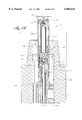
- FIGS. 2A through 2D comprise a partial sectional side view of the pulser portion of the tool of FIG. 1.
- Tool 11 for use in a well is shown.
- Tool 11 is typically lowered into a well through the inner diameter of a string of drill pipe 15 and a muleshoe sub 16 on a wireline (not shown). The wireline is then retrieved.
- Drilling fluid is supplied to the drill bit (not shown) in the annulus 18 between tool 11 and drill pipe 15.
- Tool 11 comprises two or more measurement instruments in a module (not shown). One of the instruments makes a gamma ray measurement of the formation being drilled. Another of the instruments measures inclination and azimuth. The measurements are digitized and a driver circuit (not shown) supplies two digital signals, on and off, to a mud pulser 31.
- the instruments in the module are conventional.
- pulser 31 creates pressure pulses in the stream of drilling fluid being circulated in annulus 18 in response to the digital signals provided by the driver circuit of the module.
- Pulser 31 has a generally cylindrical, hollow pulser body 33 with a number of body segments rigidly secured to one another. The lowermost segment of body 33, body segment 33h, lands on a shoulder 35 on a lower end of drill string 15 (FIG. 2D). The lower end of body segment 33h has a lateral passage 36 and an annular ring 34 with an axial orifice 37 through which drilling fluid in annulus 18 flows to the drill bit (not shown).
- a piston 41 slidingly reciprocates within an axial bore 42 in body segment 33g.
- Piston 41 has a lower tubular extension 41a, an axial bore 44 and a signal poppet 43 secured to a lower end of extension 41a.
- Signal poppet 43 is also hollow so that drilling fluid may flow through body segments 33d, 33e, 33f, bore 44 and out signal poppet 43 as well as around pulser 31 in annulus 18.
- a flange 41b at a lower end of piston 41 limits the downward movement of piston 41 by landing on an upper rim 46 on body segment 33g.
- Fluid pressure P3 enters a passage 36 in body segment 33f to apply pressure to flange 41b and force piston 41 upward.
- An upper end 41c of piston 41 limits its upward movement by bumping against a lower rim 48 on body segment 33e.
- a centralizer 42 extends outward from body segment 33f to centralize pulser 31 in muleshoe sub 16.
- Piston 41 and signal poppet 43 are shown in an extended position in which signal poppet 43 extends into and partially obstructs orifice 37 in order to reduce the flow of drilling fluid and create a mud pressure pulse in annulus 18. Piston 41 and signal poppet 43 also have an open position (not shown) wherein signal poppet 43 is located above and does not obstruct orifice 37 in order to increase the flow of drilling fluid therethrough and eliminate the mud pulse.
- a strong compression spring 45 is located within body segment 33f between upper end 41c and a lower end of body segment 33e for biasing piston 41 to the closed position.
- a bi-directional solenoid 51 is located above piston 41 within a chamber 52 in body segment 33c.
- Solenoid 51 has an upper electromagnetic coil 53, an immediately adjacent lower electromagnetic coil 55, and an axially moveable solenoid shaft 57.
- Solenoid shaft 57 is closely received by coils 53, 55.
- a servo poppet rod 57a is threadingly secured to a lower end of solenoid shaft 57.
- Servo poppet rod 57a extends downward through an axial bore 58 in body segment 33c.
- a lower end of servo poppet rod 57a is sealed in an expansible bellows 60 within a cylindrical housing 62, both of which extend into body segment 33d from a lower side of body segment 33c.
- Bellows 60 seals coils 53, 55 from drilling fluid.
- a servo rod centralizer 62a in housing 62 helps maintain servo poppet rod 57a in an axially centralized position.
- servo poppet rod 57a operates as a servo poppet by opening and closing an opening 63.
- Opening 63 is located in an annular ring 66 which is secured in an upper end of hollow body segment 33e. Opening 63 is slightly smaller than the diameter of rod 57a and smaller in diameter than orifice 37 (FIG. 2D).
- a lateral passage 65 extends through body segment 33d for communicating drilling fluid to opening 63 and body segments 33e, 33f to act on upper end 41c of piston 41 (FIGS. 2C and 2D).
- Rod 57a is movable between a closed position (not shown) for obstructing fluid flow through opening 63 (not shown), and an open position for allowing fluid flow through opening 63 (FIG. 2C).
- the driver sends a signal to solenoid 51. Electrical current is applied to one of coils 53, 55 to overcome the differential pressure exerted by the drilling fluid tending to keep the lower end of rod 57a in opening 63. After rod 57a disengages opening 63, a lesser amount of current is required to keep rod 57a maintained in the open position.
- the instruments in the module and the driver may be programmed to keep rod 57a in the open position for one-quarter to three seconds.
- the driver provides another signal after the first signal goes off. With the second signal, current is applied to the other of coils 53, 55 to force shaft 57 downward. Once rod 57a lands in opening 63, the fluid pressure created by the surrounding flowing fluid is sufficient to keep it there without stimulating coil 53 or 55. Only one of coils 53, 55 is engaged at one time since one of the coils 53 or 55 is configured to lift and hold shaft 57 and the other is configured to push down on shaft 57.
- mud pulser 31 also has a flow switch assembly 71 for sensing when mud circulation occurs.
- Flow switch assembly 71 energizes the module through wire 77 to provide signals to solenoid 51 through wire 77a upon commencement of mud circulation.
- Flow switch assembly 71 is located in a chamber 73 in body segment 33a above solenoid 51.
- a plurality of diagonal ports 75 extend through body segment 33a for communicating drilling fluid to chamber 73.
- Flow switch assembly 71 has a collapsible bellows 79 which contains an axially movable plunger 81.
- Bellows 79 contracts in response to a mud flow pressure differential between pressure P2 at passages 65 and pressure P1 at ports 75. When bellows 79 contracts, plunger 81 is moved downward to close a switch 82.
- Switch 82 is connected to the driver and measurement circuits by wire 77 to turn on the measuring and driver circuits.
- mud pulser 31 is lowered into or otherwise installed in drill string 15.
- signal poppet 43 will be biased to the lower position by spring 45 as shown in FIG. 2D.
- rod 57a is in its default closed position in opening 63 due to gravity. Rod 57a remains in the closed position until a signal is sent from the driver.
- signal poppet 43 moves upward to the open position since the pressure above piston 41 is lower than the pressure below it.
- the pressure above piston 41 is substantially the same as pressure P4 (FIG. 2D) at the inlet to piston extension bore 44, while the pressure below piston 41 is P3 (FIG. 2C).
- Bellows 79 collapses under the pressure differential and actuates the system.
- the instruments take various measurements which are communicated through the driver and pulser 31 to the surface in the form of drilling mud pulses.
- a mud pulse is generated when coil 53 is energized by a signal from the driver.
- shaft 57 moves rod 57a to the open position to allow drilling fluid to flow through opening 63.
- the force of spring 45 coupled with pressure P2 overcomes force P3 on piston 41, forcing signal poppet 43 downward into the extended position. This restricts mud flow through drill pipe 15, creating a sharp pulse.
- Shaft 57 is held in its open position by energized coil 53.
- the driver then simultaneously de-energizes coil 53 and energizes coil 55.
- shaft 57 moves rod 57a to its closed position rapidly to reduce pressure P2 from applying pressure to upper end 41c of piston 41.
- Pressure P3 on flange 41b of piston 41 overcomes the force of spring 45 and causes signal poppet 43 to move quickly upward into the open position so that unobstructed fluid flow resumes.
- the opening and closing of signal poppet 43 creates a sharp pulse which is detected at the surface.
- the invention has several advantages.
- the bidirectional solenoid provides very quick, precise control of the signal poppet since each step is timed electronically.
- the pulser also requires fewer moving parts than conventional pulsers.
- this pulser provides longer battery life since it requires less energy consumption at each operational step.
Abstract
Description
Claims (17)
Priority Applications (4)
| Application Number | Priority Date | Filing Date | Title |
|---|---|---|---|
| US08/917,624 US6002643A (en) | 1997-08-19 | 1997-08-19 | Pulser |
| GB9809051A GB2328459B (en) | 1997-08-19 | 1998-04-29 | Improved pulser |
| CA002237017A CA2237017A1 (en) | 1997-08-19 | 1998-05-06 | Improved pulser |
| FR9810397A FR2767556A1 (en) | 1997-08-19 | 1998-08-13 | MEASURING TOOL DURING DRILLING TO BE INSTALLED IN A DRILL ROD TRAIN AND PULSE GENERATOR FOR SUCH A TOOL |
Applications Claiming Priority (1)
| Application Number | Priority Date | Filing Date | Title |
|---|---|---|---|
| US08/917,624 US6002643A (en) | 1997-08-19 | 1997-08-19 | Pulser |
Publications (1)
| Publication Number | Publication Date |
|---|---|
| US6002643A true US6002643A (en) | 1999-12-14 |
Family
ID=25439071
Family Applications (1)
| Application Number | Title | Priority Date | Filing Date |
|---|---|---|---|
| US08/917,624 Expired - Lifetime US6002643A (en) | 1997-08-19 | 1997-08-19 | Pulser |
Country Status (4)
| Country | Link |
|---|---|
| US (1) | US6002643A (en) |
| CA (1) | CA2237017A1 (en) |
| FR (1) | FR2767556A1 (en) |
| GB (1) | GB2328459B (en) |
Cited By (35)
| Publication number | Priority date | Publication date | Assignee | Title |
|---|---|---|---|---|
| US20020159333A1 (en) * | 2001-03-13 | 2002-10-31 | Baker Hughes Incorporated | Hydraulically balanced reciprocating pulser valve for mud pulse telemetry |
| US20030205428A1 (en) * | 2002-04-25 | 2003-11-06 | Schlumberger Technology Corporation | Acoustic source using a shaftless electrical hammer |
| US20050231383A1 (en) * | 2004-04-06 | 2005-10-20 | Pratt F D | Intelligent efficient servo-actuator for a downhole pulser |
| US20050260089A1 (en) * | 2001-03-13 | 2005-11-24 | Baker Hughes Incorporated | Reciprocating pulser for mud pulse telemetry |
| US20060072374A1 (en) * | 2004-10-01 | 2006-04-06 | Teledrill Inc. | Measurement while drilling bi-directional pulser operating in a near laminar annular flow channel |
| US20060164918A1 (en) * | 2005-01-13 | 2006-07-27 | Halliburton Energy Services, Inc. | Methods and systems for transmitting and receiving a discrete multi-tone modulated signal in a fluid |
| US20060219438A1 (en) * | 2005-04-05 | 2006-10-05 | Halliburton Energy Services, Inc. | Wireless communications in a drilling operations environment |
| US20060233544A1 (en) * | 2005-04-11 | 2006-10-19 | Roman Coppola | Bipod platform system for a camera |
| US7145834B1 (en) * | 2006-02-14 | 2006-12-05 | Jeter John D | Well bore communication pulser |
| US20080002525A1 (en) * | 2006-06-30 | 2008-01-03 | Pratt F Dale | Rotary pulser |
| US20080142225A1 (en) * | 2006-12-14 | 2008-06-19 | Schlumberger Technology Corporation | Chemical deployment canisters for downhole use |
| US20080179093A1 (en) * | 2007-01-25 | 2008-07-31 | David John Kusko | Measurement while drilling pulser with turbine power generation unit |
| US7423932B1 (en) * | 2006-04-12 | 2008-09-09 | John Jeter | Well bore communication pulser |
| US20100147525A1 (en) * | 2008-12-17 | 2010-06-17 | Daniel Maurice Lerner | High pressure fast response sealing system for flow modulating devices |
| US7986245B1 (en) * | 2006-11-01 | 2011-07-26 | Steertek Ltd. | Measurement while drilling mud pulser control valve mechanism |
| WO2013148005A1 (en) * | 2011-12-23 | 2013-10-03 | Robert Macdonald | Controlled full flow pressure pulser for measurement while drilling (mwd) device |
| US8684093B2 (en) | 2010-04-23 | 2014-04-01 | Bench Tree Group, Llc | Electromechanical actuator apparatus and method for down-hole tools |
| US9038735B2 (en) | 2010-04-23 | 2015-05-26 | Bench Tree Group LLC | Electromechanical actuator apparatus and method for down-hole tools |
| US9091143B2 (en) | 2010-04-23 | 2015-07-28 | Bench Tree Group LLC | Electromechanical actuator apparatus and method for down-hole tools |
| WO2016089402A1 (en) * | 2014-12-04 | 2016-06-09 | Halliburton Energy Services, Inc. | Telemetry module with push only gate valve action |
| US9453410B2 (en) | 2013-06-21 | 2016-09-27 | Evolution Engineering Inc. | Mud hammer |
| WO2016187253A1 (en) * | 2015-05-18 | 2016-11-24 | Baker Hughes Incorporated | Apparatus for generating pulses in fluid during drilling of wellbores |
| US9556682B2 (en) | 2013-03-15 | 2017-01-31 | Smith International, Inc. | Underreamer for increasing a wellbore diameter |
| US9581267B2 (en) | 2011-04-06 | 2017-02-28 | David John Kusko | Hydroelectric control valve for remote locations |
| US20170167252A1 (en) * | 2015-12-15 | 2017-06-15 | Extensive Energy Technologies Partnership | Solenoid actuator for mud pulse telemetry |
| US9702204B2 (en) | 2014-04-17 | 2017-07-11 | Teledrill, Inc. | Controlled pressure pulser for coiled tubing measurement while drilling applications |
| CN108953271A (en) * | 2018-09-10 | 2018-12-07 | 中国石油集团西部钻探工程有限公司 | The energy-saving MWD pulser servo valve of hydraulic resistance balance |
| US10214980B2 (en) | 2014-06-30 | 2019-02-26 | Schlumberger Technology Corporation | Measuring fluid properties in a downhole tool |
| US10253623B2 (en) | 2016-03-11 | 2019-04-09 | Baker Hughes, A Ge Compant, Llc | Diamond high temperature shear valve designed to be used in extreme thermal environments |
| US10364671B2 (en) | 2016-03-10 | 2019-07-30 | Baker Hughes, A Ge Company, Llc | Diamond tipped control valve used for high temperature drilling applications |
| US10422201B2 (en) | 2016-03-10 | 2019-09-24 | Baker Hughes, A Ge Company, Llc | Diamond tipped control valve used for high temperature drilling applications |
| US10436025B2 (en) | 2016-03-11 | 2019-10-08 | Baker Hughes, A Ge Company, Llc | Diamond high temperature shear valve designed to be used in extreme thermal environments |
| US10633968B2 (en) | 2011-12-23 | 2020-04-28 | Teledrill, Inc. | Controlled pressure pulser for coiled tubing measurement while drilling applications |
| US10669812B2 (en) | 2016-03-10 | 2020-06-02 | Baker Hughes, A Ge Company, Llc | Magnetic sleeve control valve for high temperature drilling applications |
| US11946338B2 (en) | 2016-03-10 | 2024-04-02 | Baker Hughes, A Ge Company, Llc | Sleeve control valve for high temperature drilling applications |
Families Citing this family (1)
| Publication number | Priority date | Publication date | Assignee | Title |
|---|---|---|---|---|
| DE60208662T2 (en) * | 2001-01-24 | 2007-01-25 | Geolink (Uk) Ltd. | PRESSURE IMPULSE GENERATOR FOR DRILLING MEASURING DURING DRILLING |
Citations (8)
| Publication number | Priority date | Publication date | Assignee | Title |
|---|---|---|---|---|
| US4276943A (en) * | 1979-09-25 | 1981-07-07 | The United States Of America As Represented By The Secretary Of The Army | Fluidic pulser |
| US4323991A (en) * | 1979-09-12 | 1982-04-06 | The United States Of America As Represented By The Secretary Of The Army | Fluidic mud pulser |
| US5103430A (en) * | 1990-11-01 | 1992-04-07 | The Bob Fournet Company | Mud pulse pressure signal generator |
| US5117398A (en) * | 1990-04-11 | 1992-05-26 | Jeter John D | Well communication pulser |
| US5333686A (en) * | 1993-06-08 | 1994-08-02 | Tensor, Inc. | Measuring while drilling system |
| US5473579A (en) * | 1993-10-25 | 1995-12-05 | Ronald L. Shaw | Well bore communication pulser |
| US5586084A (en) * | 1994-12-20 | 1996-12-17 | Halliburton Company | Mud operated pulser |
| US5678630A (en) * | 1996-04-22 | 1997-10-21 | Mwd Services, Inc. | Directional drilling apparatus |
Family Cites Families (1)
| Publication number | Priority date | Publication date | Assignee | Title |
|---|---|---|---|---|
| GB2157345A (en) * | 1984-04-12 | 1985-10-23 | Dies Downhole Drilling Inc | Mud pulse telemetry tool |
-
1997
- 1997-08-19 US US08/917,624 patent/US6002643A/en not_active Expired - Lifetime
-
1998
- 1998-04-29 GB GB9809051A patent/GB2328459B/en not_active Expired - Fee Related
- 1998-05-06 CA CA002237017A patent/CA2237017A1/en not_active Abandoned
- 1998-08-13 FR FR9810397A patent/FR2767556A1/en not_active Withdrawn
Patent Citations (8)
| Publication number | Priority date | Publication date | Assignee | Title |
|---|---|---|---|---|
| US4323991A (en) * | 1979-09-12 | 1982-04-06 | The United States Of America As Represented By The Secretary Of The Army | Fluidic mud pulser |
| US4276943A (en) * | 1979-09-25 | 1981-07-07 | The United States Of America As Represented By The Secretary Of The Army | Fluidic pulser |
| US5117398A (en) * | 1990-04-11 | 1992-05-26 | Jeter John D | Well communication pulser |
| US5103430A (en) * | 1990-11-01 | 1992-04-07 | The Bob Fournet Company | Mud pulse pressure signal generator |
| US5333686A (en) * | 1993-06-08 | 1994-08-02 | Tensor, Inc. | Measuring while drilling system |
| US5473579A (en) * | 1993-10-25 | 1995-12-05 | Ronald L. Shaw | Well bore communication pulser |
| US5586084A (en) * | 1994-12-20 | 1996-12-17 | Halliburton Company | Mud operated pulser |
| US5678630A (en) * | 1996-04-22 | 1997-10-21 | Mwd Services, Inc. | Directional drilling apparatus |
Cited By (58)
| Publication number | Priority date | Publication date | Assignee | Title |
|---|---|---|---|---|
| US20020159333A1 (en) * | 2001-03-13 | 2002-10-31 | Baker Hughes Incorporated | Hydraulically balanced reciprocating pulser valve for mud pulse telemetry |
| US6898150B2 (en) | 2001-03-13 | 2005-05-24 | Baker Hughes Incorporated | Hydraulically balanced reciprocating pulser valve for mud pulse telemetry |
| US20050260089A1 (en) * | 2001-03-13 | 2005-11-24 | Baker Hughes Incorporated | Reciprocating pulser for mud pulse telemetry |
| US7417920B2 (en) * | 2001-03-13 | 2008-08-26 | Baker Hughes Incorporated | Reciprocating pulser for mud pulse telemetry |
| US20030205428A1 (en) * | 2002-04-25 | 2003-11-06 | Schlumberger Technology Corporation | Acoustic source using a shaftless electrical hammer |
| US6782970B2 (en) * | 2002-04-25 | 2004-08-31 | Schlumberger Technology Corporation | Acoustic source using a shaftless electrical hammer |
| US20050231383A1 (en) * | 2004-04-06 | 2005-10-20 | Pratt F D | Intelligent efficient servo-actuator for a downhole pulser |
| US8203908B2 (en) | 2004-04-06 | 2012-06-19 | Newsco Directional Support Services Inc. | Intelligent efficient servo-actuator for a downhole pulser |
| US20090267791A1 (en) * | 2004-04-06 | 2009-10-29 | Pratt F Dale | Intelligent efficient servo-actuator for a downhole pulser |
| US7564741B2 (en) | 2004-04-06 | 2009-07-21 | Newsco Directional And Horizontal Drilling Services Inc. | Intelligent efficient servo-actuator for a downhole pulser |
| US20080267011A1 (en) * | 2004-04-06 | 2008-10-30 | Newsco Directional & Horizontal Drilling Services Inc. | Intelligent efficient servo-actuator for a downhole pulser |
| US9644477B2 (en) | 2004-07-01 | 2017-05-09 | Halliburton Energy Services, Inc. | Wireless communications in a drilling operations environment |
| US20060072374A1 (en) * | 2004-10-01 | 2006-04-06 | Teledrill Inc. | Measurement while drilling bi-directional pulser operating in a near laminar annular flow channel |
| US7180826B2 (en) | 2004-10-01 | 2007-02-20 | Teledrill Inc. | Measurement while drilling bi-directional pulser operating in a near laminar annular flow channel |
| US7187298B2 (en) | 2005-01-13 | 2007-03-06 | Halliburton Energy Services, Inc. | Methods and systems for transmitting and receiving a discrete multi-tone modulated signal in a fluid |
| US20060164918A1 (en) * | 2005-01-13 | 2006-07-27 | Halliburton Energy Services, Inc. | Methods and systems for transmitting and receiving a discrete multi-tone modulated signal in a fluid |
| US20060219438A1 (en) * | 2005-04-05 | 2006-10-05 | Halliburton Energy Services, Inc. | Wireless communications in a drilling operations environment |
| US8544564B2 (en) | 2005-04-05 | 2013-10-01 | Halliburton Energy Services, Inc. | Wireless communications in a drilling operations environment |
| US20060233544A1 (en) * | 2005-04-11 | 2006-10-19 | Roman Coppola | Bipod platform system for a camera |
| NO342358B1 (en) * | 2005-05-24 | 2018-05-14 | Baker Hughes Inc | Reciprocating pulse sensor for mud pulse telemetry and a method for transmitting pressure pulses from a downhole site through a flowing fluid into a borehole |
| GB2440868B (en) * | 2005-05-24 | 2010-12-22 | Baker Hughes Inc | Reciprocating pulser for mud pulse telemetry |
| US7145834B1 (en) * | 2006-02-14 | 2006-12-05 | Jeter John D | Well bore communication pulser |
| US7423932B1 (en) * | 2006-04-12 | 2008-09-09 | John Jeter | Well bore communication pulser |
| US20080002525A1 (en) * | 2006-06-30 | 2008-01-03 | Pratt F Dale | Rotary pulser |
| US7719439B2 (en) | 2006-06-30 | 2010-05-18 | Newsco Directional And Horizontal Drilling Services Inc. | Rotary pulser |
| US7986245B1 (en) * | 2006-11-01 | 2011-07-26 | Steertek Ltd. | Measurement while drilling mud pulser control valve mechanism |
| US20080142225A1 (en) * | 2006-12-14 | 2008-06-19 | Schlumberger Technology Corporation | Chemical deployment canisters for downhole use |
| US7546878B2 (en) * | 2006-12-14 | 2009-06-16 | Schlumberger Technology Corporation | Chemical deployment canisters for downhole use |
| US20080179093A1 (en) * | 2007-01-25 | 2008-07-31 | David John Kusko | Measurement while drilling pulser with turbine power generation unit |
| US8138943B2 (en) | 2007-01-25 | 2012-03-20 | David John Kusko | Measurement while drilling pulser with turbine power generation unit |
| US8720572B2 (en) | 2008-12-17 | 2014-05-13 | Teledrill, Inc. | High pressure fast response sealing system for flow modulating devices |
| US20100147525A1 (en) * | 2008-12-17 | 2010-06-17 | Daniel Maurice Lerner | High pressure fast response sealing system for flow modulating devices |
| US9038735B2 (en) | 2010-04-23 | 2015-05-26 | Bench Tree Group LLC | Electromechanical actuator apparatus and method for down-hole tools |
| US9091143B2 (en) | 2010-04-23 | 2015-07-28 | Bench Tree Group LLC | Electromechanical actuator apparatus and method for down-hole tools |
| US8684093B2 (en) | 2010-04-23 | 2014-04-01 | Bench Tree Group, Llc | Electromechanical actuator apparatus and method for down-hole tools |
| US9920886B2 (en) | 2011-04-06 | 2018-03-20 | David John Kusko | Hydroelectric control valve for remote locations |
| US9581267B2 (en) | 2011-04-06 | 2017-02-28 | David John Kusko | Hydroelectric control valve for remote locations |
| WO2013148005A1 (en) * | 2011-12-23 | 2013-10-03 | Robert Macdonald | Controlled full flow pressure pulser for measurement while drilling (mwd) device |
| US10633968B2 (en) | 2011-12-23 | 2020-04-28 | Teledrill, Inc. | Controlled pressure pulser for coiled tubing measurement while drilling applications |
| US10947787B2 (en) | 2013-03-15 | 2021-03-16 | Smith International, Inc. | Underreamer for increasing a wellbore diameter |
| US9556682B2 (en) | 2013-03-15 | 2017-01-31 | Smith International, Inc. | Underreamer for increasing a wellbore diameter |
| US10190368B2 (en) | 2013-03-15 | 2019-01-29 | Smith International, Inc. | Underreamer for increasing a wellbore diameter |
| US9453410B2 (en) | 2013-06-21 | 2016-09-27 | Evolution Engineering Inc. | Mud hammer |
| US9702204B2 (en) | 2014-04-17 | 2017-07-11 | Teledrill, Inc. | Controlled pressure pulser for coiled tubing measurement while drilling applications |
| US10214980B2 (en) | 2014-06-30 | 2019-02-26 | Schlumberger Technology Corporation | Measuring fluid properties in a downhole tool |
| US11015406B2 (en) | 2014-06-30 | 2021-05-25 | Schlumberger Technology Corporation | Sensor activated downhole cutting tool |
| US10180058B2 (en) | 2014-12-04 | 2019-01-15 | Halliburton Energy Services, Inc. | Telemetry module with push only gate valve action |
| WO2016089402A1 (en) * | 2014-12-04 | 2016-06-09 | Halliburton Energy Services, Inc. | Telemetry module with push only gate valve action |
| WO2016187253A1 (en) * | 2015-05-18 | 2016-11-24 | Baker Hughes Incorporated | Apparatus for generating pulses in fluid during drilling of wellbores |
| US9879528B2 (en) * | 2015-12-15 | 2018-01-30 | Extensive Energy Technologies Partnership | Solenoid actuator for mud pulse telemetry |
| US20170167252A1 (en) * | 2015-12-15 | 2017-06-15 | Extensive Energy Technologies Partnership | Solenoid actuator for mud pulse telemetry |
| US10422201B2 (en) | 2016-03-10 | 2019-09-24 | Baker Hughes, A Ge Company, Llc | Diamond tipped control valve used for high temperature drilling applications |
| US10669812B2 (en) | 2016-03-10 | 2020-06-02 | Baker Hughes, A Ge Company, Llc | Magnetic sleeve control valve for high temperature drilling applications |
| US10364671B2 (en) | 2016-03-10 | 2019-07-30 | Baker Hughes, A Ge Company, Llc | Diamond tipped control valve used for high temperature drilling applications |
| US11946338B2 (en) | 2016-03-10 | 2024-04-02 | Baker Hughes, A Ge Company, Llc | Sleeve control valve for high temperature drilling applications |
| US10436025B2 (en) | 2016-03-11 | 2019-10-08 | Baker Hughes, A Ge Company, Llc | Diamond high temperature shear valve designed to be used in extreme thermal environments |
| US10253623B2 (en) | 2016-03-11 | 2019-04-09 | Baker Hughes, A Ge Compant, Llc | Diamond high temperature shear valve designed to be used in extreme thermal environments |
| CN108953271A (en) * | 2018-09-10 | 2018-12-07 | 中国石油集团西部钻探工程有限公司 | The energy-saving MWD pulser servo valve of hydraulic resistance balance |
Also Published As
| Publication number | Publication date |
|---|---|
| GB2328459A (en) | 1999-02-24 |
| FR2767556A1 (en) | 1999-02-26 |
| GB9809051D0 (en) | 1998-06-24 |
| GB2328459B (en) | 2001-10-31 |
| CA2237017A1 (en) | 1999-02-19 |
Similar Documents
| Publication | Publication Date | Title |
|---|---|---|
| US6002643A (en) | Pulser | |
| US9013957B2 (en) | Full flow pulser for measurement while drilling (MWD) device | |
| EP2106559B1 (en) | Measurement while drilling pulser with turbine power generation unit | |
| US7180826B2 (en) | Measurement while drilling bi-directional pulser operating in a near laminar annular flow channel | |
| US4386422A (en) | Servo valve for well-logging telemetry | |
| US5333686A (en) | Measuring while drilling system | |
| US4742498A (en) | Pilot operated mud pulse valve and method of operating the same | |
| US5660238A (en) | Switch actuator and flow restrictor pilot valve assembly for measurement while drilling tools | |
| US20090016159A1 (en) | Downhole tool and method | |
| US11661806B2 (en) | Downhole valve spanning a tool joint and methods of making and using same | |
| US9932774B2 (en) | Hydraulically actuated apparatus for generating pressure pulses in a drilling fluid | |
| US10487603B2 (en) | System and method for flow diversion | |
| EP2815063B1 (en) | Controlled full flow pressure pulser for measurement while drilling (mwd) device | |
| CA2649193C (en) | Measurement while drilling tool and method | |
| US7986245B1 (en) | Measurement while drilling mud pulser control valve mechanism | |
| US20230313677A1 (en) | Top- mounted mud-telemetry pulser assembly for downhole communications, and downhole valve | |
| CA2083483A1 (en) | Hydraulic system for electronically controlled pressure activated downhole testing tool |
Legal Events
| Date | Code | Title | Description |
|---|---|---|---|
| AS | Assignment |
Owner name: COMPUTALOG LIMITED, CANADA Free format text: ;ASSIGNORS:TCHAKAROV, BORISLAV J.;SEUTTER, DANIEL C.;REEL/FRAME:008788/0917;SIGNING DATES FROM 19970806 TO 19970814 Owner name: COMPUTALOG LIMITED, ALBERTA Free format text: ASSIGNMENT OF ASSIGNORS INTEREST;ASSIGNORS:TCHAKAROV, BORISLAV J.;SEUTTER, DANIEL C.;REEL/FRAME:010232/0502;SIGNING DATES FROM 19970806 TO 19970814 |
|
| STCF | Information on status: patent grant |
Free format text: PATENTED CASE |
|
| CC | Certificate of correction | ||
| FEPP | Fee payment procedure |
Free format text: PAYOR NUMBER ASSIGNED (ORIGINAL EVENT CODE: ASPN); ENTITY STATUS OF PATENT OWNER: LARGE ENTITY |
|
| FPAY | Fee payment |
Year of fee payment: 4 |
|
| AS | Assignment |
Owner name: PRECISION DRILLING TECHNOLOGY SERVICES GROUP, INC. Free format text: CHANGE OF NAME;ASSIGNOR:COMPUTALOG LTD.;REEL/FRAME:017275/0188 Effective date: 20011231 |
|
| AS | Assignment |
Owner name: PRECISION ENERGY SERVICES, LTD., CANADA Free format text: CHANGE OF NAME;ASSIGNOR:PRECISION DRILLING TECHNOLOGY SERVICES GROUP, INC.;REEL/FRAME:016345/0078 Effective date: 20050404 |
|
| AS | Assignment |
Owner name: PRECISION DRILLING TECHNOLOGY SERVICES GROUP, INC. Free format text: CHANGE OF NAME;ASSIGNOR:COMPUTALOG LTD.;REEL/FRAME:017230/0980 Effective date: 20011231 |
|
| AS | Assignment |
Owner name: PRECISION ENERGY SERVICES ULC, CANADA Free format text: ASSIGNMENT OF ASSIGNORS INTEREST;ASSIGNOR:PRECISION ENERGY SERVICES LTD.;REEL/FRAME:017507/0031 Effective date: 20060331 |
|
| AS | Assignment |
Owner name: WEATHERFORD CANADA PARTNERSHIP, CANADA Free format text: ASSIGNMENT OF ASSIGNORS INTEREST;ASSIGNOR:PRECISION ENERGY SERVICES ULC;REEL/FRAME:017527/0191 Effective date: 20060421 |
|
| FPAY | Fee payment |
Year of fee payment: 8 |
|
| FEPP | Fee payment procedure |
Free format text: PAYOR NUMBER ASSIGNED (ORIGINAL EVENT CODE: ASPN); ENTITY STATUS OF PATENT OWNER: LARGE ENTITY Free format text: PAYER NUMBER DE-ASSIGNED (ORIGINAL EVENT CODE: RMPN); ENTITY STATUS OF PATENT OWNER: LARGE ENTITY |
|
| FPAY | Fee payment |
Year of fee payment: 12 |
|
| AS | Assignment |
Owner name: WEATHERFORD TECHNOLOGY HOLDINGS, LLC, TEXAS Free format text: ASSIGNMENT OF ASSIGNORS INTEREST;ASSIGNOR:WEATHERFORD CANADA PARTNERSHIP;REEL/FRAME:042457/0086 Effective date: 20151201 |