EP2694323B1 - Siège réglable - Google Patents
Siège réglable Download PDFInfo
- Publication number
- EP2694323B1 EP2694323B1 EP12724159.4A EP12724159A EP2694323B1 EP 2694323 B1 EP2694323 B1 EP 2694323B1 EP 12724159 A EP12724159 A EP 12724159A EP 2694323 B1 EP2694323 B1 EP 2694323B1
- Authority
- EP
- European Patent Office
- Prior art keywords
- rod
- coupling
- support
- frame
- pair
- Prior art date
- Legal status (The legal status is an assumption and is not a legal conclusion. Google has not performed a legal analysis and makes no representation as to the accuracy of the status listed.)
- Active
Links
- 230000008878 coupling Effects 0.000 claims description 86
- 238000010168 coupling process Methods 0.000 claims description 86
- 238000005859 coupling reaction Methods 0.000 claims description 86
- 239000000463 material Substances 0.000 description 10
- XAGFODPZIPBFFR-UHFFFAOYSA-N aluminium Chemical compound [Al] XAGFODPZIPBFFR-UHFFFAOYSA-N 0.000 description 1
- 229910052782 aluminium Inorganic materials 0.000 description 1
- 239000000969 carrier Substances 0.000 description 1
- 239000002131 composite material Substances 0.000 description 1
- 230000000694 effects Effects 0.000 description 1
- 239000006261 foam material Substances 0.000 description 1
- 239000010985 leather Substances 0.000 description 1
- 239000007769 metal material Substances 0.000 description 1
- 239000000203 mixture Substances 0.000 description 1
- 239000004745 nonwoven fabric Substances 0.000 description 1
- 239000004033 plastic Substances 0.000 description 1
- 229920003023 plastic Polymers 0.000 description 1
- 230000000284 resting effect Effects 0.000 description 1
- 229910001220 stainless steel Inorganic materials 0.000 description 1
- 239000010935 stainless steel Substances 0.000 description 1
- 229920002994 synthetic fiber Polymers 0.000 description 1
- 239000004753 textile Substances 0.000 description 1
- 239000003190 viscoelastic substance Substances 0.000 description 1
- 239000002759 woven fabric Substances 0.000 description 1
Images


Classifications
-
- B—PERFORMING OPERATIONS; TRANSPORTING
- B60—VEHICLES IN GENERAL
- B60N—SEATS SPECIALLY ADAPTED FOR VEHICLES; VEHICLE PASSENGER ACCOMMODATION NOT OTHERWISE PROVIDED FOR
- B60N2/00—Seats specially adapted for vehicles; Arrangement or mounting of seats in vehicles
- B60N2/02—Seats specially adapted for vehicles; Arrangement or mounting of seats in vehicles the seat or part thereof being movable, e.g. adjustable
- B60N2/04—Seats specially adapted for vehicles; Arrangement or mounting of seats in vehicles the seat or part thereof being movable, e.g. adjustable the whole seat being movable
- B60N2/045—Longitudinal adjustment by means of articulated rods supporting the seat, e.g. parallelogram mechanisms
-
- B—PERFORMING OPERATIONS; TRANSPORTING
- B60—VEHICLES IN GENERAL
- B60N—SEATS SPECIALLY ADAPTED FOR VEHICLES; VEHICLE PASSENGER ACCOMMODATION NOT OTHERWISE PROVIDED FOR
- B60N2/00—Seats specially adapted for vehicles; Arrangement or mounting of seats in vehicles
- B60N2/02—Seats specially adapted for vehicles; Arrangement or mounting of seats in vehicles the seat or part thereof being movable, e.g. adjustable
- B60N2/04—Seats specially adapted for vehicles; Arrangement or mounting of seats in vehicles the seat or part thereof being movable, e.g. adjustable the whole seat being movable
- B60N2/06—Seats specially adapted for vehicles; Arrangement or mounting of seats in vehicles the seat or part thereof being movable, e.g. adjustable the whole seat being movable slidable
- B60N2/062—Seats specially adapted for vehicles; Arrangement or mounting of seats in vehicles the seat or part thereof being movable, e.g. adjustable the whole seat being movable slidable transversally slidable
-
- B—PERFORMING OPERATIONS; TRANSPORTING
- B60—VEHICLES IN GENERAL
- B60N—SEATS SPECIALLY ADAPTED FOR VEHICLES; VEHICLE PASSENGER ACCOMMODATION NOT OTHERWISE PROVIDED FOR
- B60N2/00—Seats specially adapted for vehicles; Arrangement or mounting of seats in vehicles
- B60N2/02—Seats specially adapted for vehicles; Arrangement or mounting of seats in vehicles the seat or part thereof being movable, e.g. adjustable
- B60N2/04—Seats specially adapted for vehicles; Arrangement or mounting of seats in vehicles the seat or part thereof being movable, e.g. adjustable the whole seat being movable
- B60N2/16—Seats specially adapted for vehicles; Arrangement or mounting of seats in vehicles the seat or part thereof being movable, e.g. adjustable the whole seat being movable height-adjustable
- B60N2/1605—Seats specially adapted for vehicles; Arrangement or mounting of seats in vehicles the seat or part thereof being movable, e.g. adjustable the whole seat being movable height-adjustable characterised by the cinematic
- B60N2/161—Rods
- B60N2/1615—Parallelogram-like structure
-
- B—PERFORMING OPERATIONS; TRANSPORTING
- B60—VEHICLES IN GENERAL
- B60N—SEATS SPECIALLY ADAPTED FOR VEHICLES; VEHICLE PASSENGER ACCOMMODATION NOT OTHERWISE PROVIDED FOR
- B60N2/00—Seats specially adapted for vehicles; Arrangement or mounting of seats in vehicles
- B60N2/02—Seats specially adapted for vehicles; Arrangement or mounting of seats in vehicles the seat or part thereof being movable, e.g. adjustable
- B60N2/04—Seats specially adapted for vehicles; Arrangement or mounting of seats in vehicles the seat or part thereof being movable, e.g. adjustable the whole seat being movable
- B60N2/16—Seats specially adapted for vehicles; Arrangement or mounting of seats in vehicles the seat or part thereof being movable, e.g. adjustable the whole seat being movable height-adjustable
- B60N2/1635—Seats specially adapted for vehicles; Arrangement or mounting of seats in vehicles the seat or part thereof being movable, e.g. adjustable the whole seat being movable height-adjustable characterised by the drive mechanism
- B60N2/164—Linear actuator, e.g. screw mechanism
-
- B—PERFORMING OPERATIONS; TRANSPORTING
- B60—VEHICLES IN GENERAL
- B60N—SEATS SPECIALLY ADAPTED FOR VEHICLES; VEHICLE PASSENGER ACCOMMODATION NOT OTHERWISE PROVIDED FOR
- B60N2/00—Seats specially adapted for vehicles; Arrangement or mounting of seats in vehicles
- B60N2/24—Seats specially adapted for vehicles; Arrangement or mounting of seats in vehicles for particular purposes or particular vehicles
-
- B—PERFORMING OPERATIONS; TRANSPORTING
- B60—VEHICLES IN GENERAL
- B60N—SEATS SPECIALLY ADAPTED FOR VEHICLES; VEHICLE PASSENGER ACCOMMODATION NOT OTHERWISE PROVIDED FOR
- B60N2/00—Seats specially adapted for vehicles; Arrangement or mounting of seats in vehicles
- B60N2/68—Seat frames
-
- B—PERFORMING OPERATIONS; TRANSPORTING
- B64—AIRCRAFT; AVIATION; COSMONAUTICS
- B64D—EQUIPMENT FOR FITTING IN OR TO AIRCRAFT; FLIGHT SUITS; PARACHUTES; ARRANGEMENT OR MOUNTING OF POWER PLANTS OR PROPULSION TRANSMISSIONS IN AIRCRAFT
- B64D11/00—Passenger or crew accommodation; Flight-deck installations not otherwise provided for
- B64D11/06—Arrangements of seats, or adaptations or details specially adapted for aircraft seats
- B64D11/0639—Arrangements of seats, or adaptations or details specially adapted for aircraft seats with features for adjustment or converting of seats
- B64D11/06395—Arrangements of seats, or adaptations or details specially adapted for aircraft seats with features for adjustment or converting of seats characterised by the arrangement of electric motors for adjustment
-
- B—PERFORMING OPERATIONS; TRANSPORTING
- B64—AIRCRAFT; AVIATION; COSMONAUTICS
- B64D—EQUIPMENT FOR FITTING IN OR TO AIRCRAFT; FLIGHT SUITS; PARACHUTES; ARRANGEMENT OR MOUNTING OF POWER PLANTS OR PROPULSION TRANSMISSIONS IN AIRCRAFT
- B64D11/00—Passenger or crew accommodation; Flight-deck installations not otherwise provided for
- B64D11/06—Arrangements of seats, or adaptations or details specially adapted for aircraft seats
- B64D11/0639—Arrangements of seats, or adaptations or details specially adapted for aircraft seats with features for adjustment or converting of seats
- B64D11/064—Adjustable inclination or position of seats
-
- B—PERFORMING OPERATIONS; TRANSPORTING
- B64—AIRCRAFT; AVIATION; COSMONAUTICS
- B64D—EQUIPMENT FOR FITTING IN OR TO AIRCRAFT; FLIGHT SUITS; PARACHUTES; ARRANGEMENT OR MOUNTING OF POWER PLANTS OR PROPULSION TRANSMISSIONS IN AIRCRAFT
- B64D11/00—Passenger or crew accommodation; Flight-deck installations not otherwise provided for
- B64D11/06—Arrangements of seats, or adaptations or details specially adapted for aircraft seats
- B64D11/0689—Arrangements of seats, or adaptations or details specially adapted for aircraft seats specially adapted for pilots
Definitions
- the field of the invention relates to pilot seats or the like.
- common carriers such as passenger airlines, bus lines, and train lines
- a cockpit or command center where the pilot or driver controls the common carrier.
- the typical seating height and/or lateral position may be insufficient for the pilot or driver to fully view his or her surroundings in order to properly anticipate, respond, and/or avoid incidents.
- the size and/or shape of the common carrier may be such that a portion of the field of vision is obstructed or difficult to easily view from the typical seating height and/or lateral position.
- Document DE202004020657 describes an adjustable seat where the pivoting couplings between a front rod and a rear rod and the upper frame or the lower frame are substantially horizontally aligned with each other.
- Documents US4047759 and US3268200 disclose an adjustable seat comprising a coupling system installed directly between the lower frame and the seat pan of the seat.
- Documents US3572828 , FR1550068 , US3139304 and EP0029997 describe other types of adjustable seats.
- the invention consists in providing an adjustable seat according to claim 1.
- a linear actuator may be coupled to the upper frame, and a track coupled to the lower frame, wherein the linear actuator is configured to travel along the track.
- the linear actuator may comprise a first end and a second end, wherein the first end is coupled to a coupling location on the lower frame and the second end is coupled to a coupling location on the coupling system.
- the coupling location on the coupling system may comprise a cross bar positioned on the upper rod or the lower rod.
- the upper frame is in a high position when the linear actuator is positioned proximate an upper end of the track and the upper rod and the lower rod are angled upward in a forward direction, and the upper frame is in a low position when the linear actuator is positioned proximate a lower end of the track and the upper rod and the lower rod are angled downward in a forward direction.
- Embodiments of the invention provide seats with a range of adjustment options. While the seats are discussed for use with aircraft, particularly as pilot seats, they are by no means so limited. Rather, embodiments of the seats may be used with any type of vehicle or otherwise as desired.
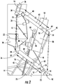
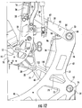
- Figures 1-13 illustrate embodiments of a seat 10.
- the seat 10 comprises an upper frame 12, a seat pan 14, a back rest 16, and a lower frame 18.
- the upper frame 12, the seat pan 14, the back rest 16, and/or the lower frame 18 may be formed of materials including but not limited to aluminum, stainless steel, other metallic materials, composite materials, or other similar materials.
- the upper frame 12 includes a pair of support arms 20.
- Each support arm 20 may have an "L" shape.
- the support arms 20 may have any suitable shape that provides sufficient support and stability for the seat 10.
- each support arm 20 may extend in a forward direction to provide support and/or a coupling location for the seat pan 14, while an upper portion 24 of each support arm 20 may extend in an upward direction to provide support and a coupling location for the back rest 16, as well as an upper rod forward pivot coupling location 25, which is discussed in detail below.
- An upper cross bar 26 may be positioned between the upper portions 24.
- a lower aft end 28 of each support arm 20 may be configured to provide a lower rod forward pivot coupling location 32, which also is discussed in detail below.
- the upper cross bar 26 and the support arms 20 serve as the primary structure of the upper frame 12.
- the upper cross bar 26 may be welded, integrally formed, or otherwise joined to the support arms 20 via mechanical fasteners, such as bolts, rivets, screws, or other suitable fasteners.
- mechanical fasteners such as bolts, rivets, screws, or other suitable fasteners.
- any suitable shape or coupling between the upper cross bar 26 and the support arms 20 may be used that will provide sufficient stability and strength for the upper frame 12.
- the seat pan 14 includes a frame 30.
- the frame 30 may be coupled to the lower portion 22 of each support arm 20 via coupling locations 34 on the frame 30 and the lower portions 22.
- mechanical fasteners such as bolts, rivets, screws, or other suitable fasteners, may be inserted through the coupling locations 34.
- the frame 30 may be welded, integrally formed, or otherwise joined to the support arms 20.
- the frame 30 may be pivotally coupled to the support arms 20.
- a pivot bar or other pivotal coupling mechanism may be inserted through the coupling locations 34 to allow the frame 30 to pivot relative to the support arm 20 (as best illustrated in Figure 9 ).
- a recline lock or other suitable mechanism may be used to control the rotation of the seat pan 14 relative to the support arm 20.
- the back rest 16 may also include a frame 36.
- the frame 36 may be coupled to the upper portion 24 of each support arm 20 via coupling locations 38 on the frame 36 and the upper portions 24.
- mechanical fasteners such as bolts, rivets, screws, or other suitable fasteners, may be inserted through the coupling locations 38.
- the frame 36 may be welded, integrally formed, or otherwise joined to the support arms 20.
- the frame 36 may be pivotally coupled to the support arms 20.
- a pivot bar or other pivotal coupling mechanism may be inserted through the coupling locations 34 to allow the frame 36 to pivot relative to the support arm 20 (as best illustrated in Figure 9 ).
- a recline lock or other suitable mechanism may be used to control the rotation of the back rest 16 relative to the support arm 20.
- the seat pan 14 and/or the back rest 16 may include a cushion to provide additional comfort and support for a person seated in the seat 10.
- the covering of the cushion may be formed of any suitable material including but not limited to textiles, woven or nonwoven fabrics, leather, synthetic materials, plastics, or other similar materials.
- the internal composition of the cushion may include any suitable material that provides a comfortable resting location for a passenger, while providing a durable material that will withstand repeated usage.
- the type of internal cushion material includes but is not limited to viscoelastic materials, foam materials, honeycomb-shaped materials, cushioning materials, or other similar materials.
- the upper frame 12 may be pivotally coupled to the lower frame 18 via a coupling system 40, which is described in detail below.
- the lower frame 18 may include a pair of support legs 42.
- Each support leg 42 may have an "L" shape.
- the support legs 42 may have any suitable shape that provides sufficient support and stability for the seat 10.
- each support leg 42 may extend in a forward direction to provide support and a forward coupling location for a forward cross bar 46, while an upper portion 48 of each support leg 42 may extend in an upward direction to provide support and an upper rod aft pivot coupling location 50, which is discussed in detail below.
- a lower aft end 52 of each support leg 42 may be configured to provide a lower rod aft pivot coupling location 54 and/or an aft coupling location for an aft cross bar 56.
- the forward cross bar 46, the aft cross bar 56, and the support legs 42 serve as the primary structure of the lower frame 18.
- the forward cross bar 46 and/or the aft cross bar 56 may be welded, integrally formed, or otherwise joined to the support legs 42 via mechanical fasteners, such as bolts, rivets, screws, or other suitable fasteners.
- mechanical fasteners such as bolts, rivets, screws, or other suitable fasteners.
- any suitable shape or coupling between the forward cross bar 46 and/or the aft cross bar 56 and the support legs 42 may be used that will provide sufficient stability and strength for the lower frame 18.
- the coupling system 40 may comprise an upper rod 58 and a lower rod 60, as shown in Figures 1-13 .
- the upper rod 58 may have a "U” or "V" shape.
- the upper rod 58 may have any suitable shape that provides sufficient coupling strength and stability for the seat 10.
- the upper rod 58 comprises a pair of extensions 62, wherein an aft end 64 of each extension 62 is coupled to a cross beam 66.
- the aft end 64 of each extension 62 may be welded, integrally formed, or otherwise joined to the cross beam 66 via mechanical fasteners, such as bolts, rivets, screws, or other suitable fasteners.
- mechanical fasteners such as bolts, rivets, screws, or other suitable fasteners.
- the cross beam 66 of the upper rod 58 is pivotally coupled to the lower rod aft pivot coupling location 54 located on the upper portion 48 of each support leg 42.
- the upper rod aft pivot coupling location 50 may include receptacles that are configured to couple the cross beam 66 to the support legs 42, while also allowing the cross beam 66 to rotate relative to the support legs 42.
- a forward end 68 of each extension 62 may be coupled to the upper rod forward pivot coupling location 25, which is located on the upper portion 24 of each support arm 20.
- the upper rod forward pivot coupling location 25 may include receptacles that are configured to couple the forward ends 68 to the support arms 20, while also allowing the extensions 62 to rotate relative to the support arms 20.
- the lower rod 60 may also have a "U” or "V” shape.
- the lower rod 60 may have any suitable shape that provides sufficient coupling strength and stability for the seat 10.
- the lower rod 60 comprises a pair of extensions 70, wherein an aft end 72 of each extension 70 is coupled to a cross beam 74.
- the aft end 72 of each extension 70 may be welded, integrally formed, or otherwise joined to the cross beam 74 via mechanical fasteners, such as bolts, rivets, screws, or other suitable fasteners.
- mechanical fasteners such as bolts, rivets, screws, or other suitable fasteners.
- any suitable shape or coupling between the pair of extensions 70 and the cross beam 74 may be used that will provide sufficient torsion beam strength for the lower rod 60.
- the cross beam 74 of the lower rod 60 is pivotally coupled to the lower rod aft pivot coupling location 54 located on the lower aft end 52 of each support leg 42.
- the lower rod aft pivot coupling location 54 may include receptacles that are configured to couple the cross beam 74 to the support legs 42, while also allowing the cross beam 74 to rotate relative to the support legs 42.
- a forward end 76 of each extension 70 may be coupled to the lower rod forward pivot coupling location 32, which is located on the lower aft end 28 of each support arm 20.
- the lower rod forward pivot coupling location 32 may include receptacles that are configured to couple the forward ends 76 to the support arms 20, while also allowing the extensions 70 to rotate relative to the support arms 20.
- the coupling system 40 may form a parallelogram shape on each side of the seat 10.
- the upper rod forward pivot coupling location 25 and the lower rod forward pivot coupling location 32 positioned on each support arm 20 are aligned substantially vertically and positioned a distance L1 from each other.
- the upper rod aft pivot coupling location 50 and the lower rod aft pivot coupling location 54 are aligned substantially vertically and also positioned a distance L1 from each other.
- the two distances L1 may form substantially vertical sides of the parallelogram shape.
- the extensions 62 of the upper rod 58 may be configured to have substantially the same length as the extensions 70 of the lower rod 60, so that the extensions 62, 70 may form the transverse sides L2 of the parallelogram shape on each side of the seat 10.
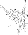
- a linear actuator 78 may be included.
- an upper end 80 of a track 82 for the linear actuator 78 may be coupled to a projection 84 positioned on the upper portion 48 of each support leg 42.
- mechanical fasteners such as bolts, rivets, screws, or other suitable fasteners, may be used to couple the upper end 80 of the track 82 to the projections 84.
- the upper end 80 of the track 82 may be pivotally coupled to the projections 84, wherein a pivot bar or other pivotal coupling mechanism may be used to allow the upper end 80 of the track 82 to pivot relative to the projections 84.
- the support legs 42 are positioned at an angle toward a central location, such that the distance between the lower portions 44 of the support legs 42 is greater than the distance between the upper portions 48 of the support legs 42.
- the shorter distance between the upper portions 48 allows the projections 84 to be positioned at a sufficiently close distance to each other to couple to the track 82 and provide support for the linear actuator 78, while also allowing the lower portions 44 to be spaced further apart to provide sufficient support for the seat 10.
- the track 82 may be a threaded rod that passes through a similarly threaded aperture in the linear actuator 78.
- a motor 86 may be coupled to the linear actuator 78, which may be operated to apply a force to move linear actuator 78 along the track 82.
- the linear actuator 78 is also coupled to the upper frame 12.
- a pair of bars 88 may extend downwardly at an angle from each end of the upper cross bar 26 toward a central location, where the bars 88 are coupled to the linear actuator 78.
- the coupling between the upper frame 12 and the linear actuator 78 allows the upper frame 12 to travel with the linear actuator 78 as it moves along the track 82.
- mechanical fasteners such as bolts, rivets, screws, or other suitable fasteners, may be used to couple the linear actuator 78 to the upper frame 12.
- the linear actuator 78 may be pivotally coupled to the upper frame 12, wherein a pivot bar or other pivotal coupling mechanism may be used to allow the linear actuator 78 to pivot relative to the upper frame 12.
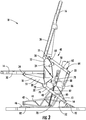
- the linear actuator 78 moves upward toward the top of the track 82 (a high position, as shown in Figure 4 )
- the upper frame 12 also moves upward, which rotates the upper rod 58 and the lower rod 60 in an upward and aft direction.
- the sides L2 of the parallelogram are angled upward in a forward direction.
- the linear actuator 78 may include a recline lock or other suitable mechanism, which may be used to control the vertical adjustment of the upper frame 12.
- a first end 96 of the linear actuator 78 may be coupled to a coupling location 98 on the lower frame 18.
- the coupling location 98 is a cross bar positioned forward and adjacent the cross beam 66.
- the coupling location 98 may be any suitable location on the lower frame 18.
- mechanical fasteners such as bolts, rivets, screws, or other suitable fasteners, may be used to couple the first end 96 of the linear actuator 78 to the coupling location 98.
- the first end 96 of the linear actuator 78 may be pivotally coupled to the coupling location 98, wherein a pivot bar or other pivotal coupling mechanism may be used to allow the linear actuator 78 to pivot relative to the lower frame 18.
- a second end 100 of the linear actuator 78 may be coupled to a coupling location 102 on the upper frame 12 and/or the coupling system 40.
- the coupling location 102 is a cross bar positioned forward and adjacent the cross beam 74.
- the coupling location 102 may be any suitable location on the upper frame 12 and/or the coupling system 40 (such as the upper rod 58) that is configured to pivot relative to the lower frame 18.
- mechanical fasteners such as bolts, rivets, screws, or other suitable fasteners, may be used to couple the second end 100 of the linear actuator 78 to the coupling location 102.
- the second end 100 of the linear actuator 78 may be pivotally coupled to the coupling location 102, wherein a pivot bar or other pivotal coupling mechanism may be used to allow the linear actuator 78 to pivot relative to the coupling system 40.
- This type of coupling arrangement allows for use of a linear actuator 78 with a shorter stroke for the same amount of travel of the upper frame 12.
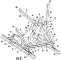
- the seat 10 may be mounted to a track 90 in a floor of a vehicle via seat track fittings 92.
- the seat track fittings 92 may be coupled to each end of the forward cross bar 46 and the aft cross bar 56.
- the forward cross bar 46 and the aft cross bar 56 may each comprise a track 94 that allows the support legs 42 to slidingly couple to the forward cross bar 46 and the aft cross bar 56. In these embodiments, the seat 10 may then slide laterally relative to the track 94.
- the support legs 42, forward cross bar 46, aft cross bar 56, and cross beams 66, 74 are configured to link the upper rod 58, the lower rod 60, and the linear actuator 78 more closely to the rear seat track fittings 92 and/or to limit the effect of floor deformation by reducing the distance of the front attachments of the lower portion 44 of each support leg 42 on the forward cross bar 46.
Landscapes
- Engineering & Computer Science (AREA)
- Aviation & Aerospace Engineering (AREA)
- Transportation (AREA)
- Mechanical Engineering (AREA)
- Seats For Vehicles (AREA)
Claims (9)
- Siège réglable (10) comprenant :un cadre supérieur (12) comprenant une paire de bras de support (20),une assise (14),un dossier (16) accouplé de manière pivotante au cadre supérieur (12) ;un cadre inférieur (18) comprenant une paire de pieds de support (42) ; etun système d'accouplement (40) comprenant une tige supérieure (58) et une tige inférieure (60) ;la tige supérieure (58) et la tige inférieure (60) étant accouplées de manière pivotante à la paire de bras de support (20) et à la paire de pieds de support (42), et la tige supérieure (58) et la tige inférieure (60) ayant des longueurs sensiblement similaires,la position de l'accouplement pivotant entre la tige supérieure (58) et la paire de bras de support (20) étant sensiblement alignée verticalement avec la position de l'accouplement pivotant entre la tige inférieure (60) et la paire de bras de support (20),la position de l'accouplement pivotant entre la tige supérieure (58) et la paire de pieds de support (42) étant sensiblement alignée verticalement avec la position de l'accouplement pivotant entre la tige inférieure (60) et la paire de pieds de support (42),caractérisé en ce que les pieds de support (42) sont positionnés angulairement en direction d'un emplacement central, de telle sorte qu'une distance entre les portions inférieures (44) des pieds de support (42) est supérieure à une distance entre les portions supérieures (48) des pieds de support (42).
- Siège réglable selon la revendication 1, dans lequel la tige supérieure (58), la tige inférieure (60), une ligne reliant les emplacements d'accouplement pivotant sensiblement verticaux sur chaque bras de support (20), et une ligne reliant les emplacements d'accouplement pivotant sensiblement verticaux sur chaque pied de support (42) ont une forme de parallélogramme.
- Siège réglable selon l'une quelconque des revendications 1 ou 2, comprenant en outre un actionneur linéaire (78) accouplé au cadre supérieur (12), et un rail accouplé au cadre inférieur (18), l'actionneur linéaire (78) étant configuré pour se déplacer le long du rail.
- Siège réglable selon l'une quelconque des revendications 1 à 3, comprenant en outre un actionneur linéaire (78) comprenant une première extrémité et une deuxième extrémité, la première extrémité étant accouplée à un emplacement d'accouplement sur le cadre inférieur (18) et la deuxième extrémité étant accouplée à un emplacement d'accouplement sur le système d'accouplement (40).
- Siège réglable selon la revendication 4, dans lequel l'emplacement d'accouplement sur le système d'accouplement (40) comprend une traverse positionnée sur la tige supérieure (58) ou la tige inférieure (60).
- Siège réglable selon la revendication 3, dans lequel le cadre supérieur (12) est en position haute lorsque l'actionneur linéaire (78) est positionné à proximité d'une extrémité supérieure du rail et que la tige supérieure (58) et la tige inférieure (60) sont inclinées vers le haut et vers l'avant, et le cadre supérieur (12) est en position basse lorsque l'actionneur linéaire (78) est positionné à proximité d'une extrémité inférieure du rail et que la tige supérieure (58) et la tige inférieure (60) sont inclinées vers le bas et vers l'avant.
- Siège réglable selon l'une quelconque des revendications 1 à 6, dans lequel les pieds de support (42) sont accouplés de manière coulissante à une traverse avant et à une traverse arrière.
- Siège réglable selon l'une quelconque des revendications 1 à 7, dans lequel l'assise (14) est accouplée de manière pivotante au cadre supérieur (12).
- Siège réglable selon l'une quelconque des revendications 1 à 8, dans lequelchaque bras de support (20) comprend une portion supérieure et une extrémité arrière ;chaque pied de support (42) comprend une portion supérieure et une extrémité arrière ;la tige supérieure (58) comprenant une paire d'extensions et une traverse, chaque extension étant accouplée de manière pivotante à la portion supérieure de chaque bras de support (20) et la traverse étant accouplée de manière pivotante à la portion supérieure de chaque pied de support (42) ; etla tige inférieure (60) comprenant une paire d'extensions et une traverse, chaque extension étant accouplée de manière pivotante à l'extrémité arrière de chaque bras de support (20) et la traverse étant accouplée de manière pivotante à l'extrémité arrière de chaque pied de support (42).
Priority Applications (1)
| Application Number | Priority Date | Filing Date | Title |
|---|---|---|---|
| EP21204479.6A EP3971027A1 (fr) | 2011-04-05 | 2012-04-05 | Siège réglable |
Applications Claiming Priority (2)
| Application Number | Priority Date | Filing Date | Title |
|---|---|---|---|
| US201161471782P | 2011-04-05 | 2011-04-05 | |
| PCT/IB2012/000948 WO2012137080A1 (fr) | 2011-04-05 | 2012-04-05 | Siège réglable |
Related Child Applications (1)
| Application Number | Title | Priority Date | Filing Date |
|---|---|---|---|
| EP21204479.6A Division EP3971027A1 (fr) | 2011-04-05 | 2012-04-05 | Siège réglable |
Publications (2)
| Publication Number | Publication Date |
|---|---|
| EP2694323A1 EP2694323A1 (fr) | 2014-02-12 |
| EP2694323B1 true EP2694323B1 (fr) | 2021-11-03 |
Family
ID=46177456
Family Applications (2)
| Application Number | Title | Priority Date | Filing Date |
|---|---|---|---|
| EP12724159.4A Active EP2694323B1 (fr) | 2011-04-05 | 2012-04-05 | Siège réglable |
| EP21204479.6A Pending EP3971027A1 (fr) | 2011-04-05 | 2012-04-05 | Siège réglable |
Family Applications After (1)
| Application Number | Title | Priority Date | Filing Date |
|---|---|---|---|
| EP21204479.6A Pending EP3971027A1 (fr) | 2011-04-05 | 2012-04-05 | Siège réglable |
Country Status (5)
| Country | Link |
|---|---|
| US (1) | US9067512B2 (fr) |
| EP (2) | EP2694323B1 (fr) |
| JP (1) | JP5759614B2 (fr) |
| CN (2) | CN104385943A (fr) |
| WO (1) | WO2012137080A1 (fr) |
Families Citing this family (11)
| Publication number | Priority date | Publication date | Assignee | Title |
|---|---|---|---|---|
| US9783310B2 (en) * | 2013-08-26 | 2017-10-10 | Ami Industries, Inc | Ejection seat pan lifter |
| US20150115126A1 (en) * | 2013-10-31 | 2015-04-30 | Sears Manufacturing Co. | Rear Mounted Vehicle Seat Suspension |
| CN104290910B (zh) * | 2014-10-22 | 2016-05-25 | 苏州华冲精密机械有限公司 | 一种飞机公务舱座椅的控制台侧面板 |
| CN105109691A (zh) * | 2015-09-15 | 2015-12-02 | 航宇救生装备有限公司 | 一种座椅靠背调节机构 |
| US11873104B2 (en) | 2016-12-07 | 2024-01-16 | Safran Seats Usa Llc | Passenger seat with variable living space |
| JP6822317B2 (ja) * | 2017-05-25 | 2021-01-27 | トヨタ紡織株式会社 | 乗物用シート |
| US10829222B2 (en) * | 2017-11-20 | 2020-11-10 | B/E Aerospace, Inc. | Aircraft passenger seat with zero-g taxi, take-off and landing recline position |
| US10632031B2 (en) * | 2018-08-21 | 2020-04-28 | Pride Mobility Products Corporation | Adjustable lift chair frame |
| CN110254727B (zh) * | 2019-06-06 | 2020-08-04 | 北京安达维尔航空设备有限公司 | 一种侧向收放的观察员座椅及其使用方法 |
| CN110155341B (zh) * | 2019-06-06 | 2020-07-28 | 北京安达维尔航空设备有限公司 | 一种观察员座椅及其使用方法 |
| US11148811B1 (en) | 2020-04-15 | 2021-10-19 | The Boeing Company | Adjustable seat pan assembly for a seat |
Citations (1)
| Publication number | Priority date | Publication date | Assignee | Title |
|---|---|---|---|---|
| US3268200A (en) * | 1963-08-24 | 1966-08-23 | Eicher Josef | Seats for vehicles |
Family Cites Families (12)
| Publication number | Priority date | Publication date | Assignee | Title |
|---|---|---|---|---|
| US2954070A (en) * | 1957-11-06 | 1960-09-27 | Calvin E Moeller | Child's seat for automobiles |
| US3139304A (en) * | 1960-10-26 | 1964-06-30 | Fritzmeier Kg Georg | Yieldable vehicle seat |
| DE1505510B2 (de) * | 1965-12-23 | 1974-07-25 | Bremshey Ag, 5650 Solingen | Abgefederter Fahrzeugsitz |
| US3572828A (en) * | 1967-10-23 | 1971-03-30 | Wilhelm Lehner | Seat for vehicle preferably agricultural vehicle |
| US4047759A (en) | 1976-07-09 | 1977-09-13 | Towmotor Corporation | Compact seat suspension for lift truck |
| DE7933733U1 (de) * | 1979-11-30 | 1980-03-06 | Bayerische Motoren Werke Ag, 8000 Muenchen | Einstellvorrichtung fuer einen verstellbaren fahrzeugsitz, insbesondere kraftfahrzeugsitz |
| US6296221B1 (en) * | 1998-11-05 | 2001-10-02 | Jacques Nadeau | Universal seat suspension system |
| CN2662742Y (zh) * | 2003-04-09 | 2004-12-15 | 宝途(知识产权)有限公司 | 排座椅 |
| DE202004020657U1 (de) * | 2004-04-29 | 2005-09-29 | Faurecia Autositze Gmbh & Co. Kg | Kraftfahrzeugsitz mit einem Sitzkissenrahmen und einem Sitzteilrahmen |
| CN201097845Y (zh) * | 2007-10-31 | 2008-08-13 | 上海市七一中学 | 预防近视椅 |
| CA2746679A1 (fr) * | 2008-12-12 | 2010-06-17 | Kids Ii, Inc. | Balancoire electromagnetique |
| FR2950607B1 (fr) * | 2009-09-30 | 2011-08-26 | Eurocopter France | Siege pour appareils volants motorises, integrant des moyens de protection du passager en cas de crash |
-
2012
- 2012-04-05 JP JP2014503234A patent/JP5759614B2/ja active Active
- 2012-04-05 US US13/440,164 patent/US9067512B2/en active Active
- 2012-04-05 EP EP12724159.4A patent/EP2694323B1/fr active Active
- 2012-04-05 CN CN201410450071.1A patent/CN104385943A/zh active Pending
- 2012-04-05 CN CN201280025312.7A patent/CN103781659B/zh not_active Expired - Fee Related
- 2012-04-05 EP EP21204479.6A patent/EP3971027A1/fr active Pending
- 2012-04-05 WO PCT/IB2012/000948 patent/WO2012137080A1/fr active Application Filing
Patent Citations (1)
| Publication number | Priority date | Publication date | Assignee | Title |
|---|---|---|---|---|
| US3268200A (en) * | 1963-08-24 | 1966-08-23 | Eicher Josef | Seats for vehicles |
Also Published As
| Publication number | Publication date |
|---|---|
| EP3971027A1 (fr) | 2022-03-23 |
| CN103781659A (zh) | 2014-05-07 |
| CN103781659B (zh) | 2016-08-17 |
| US9067512B2 (en) | 2015-06-30 |
| CN104385943A (zh) | 2015-03-04 |
| JP5759614B2 (ja) | 2015-08-05 |
| WO2012137080A1 (fr) | 2012-10-11 |
| EP2694323A1 (fr) | 2014-02-12 |
| US20120256457A1 (en) | 2012-10-11 |
| JP2014509989A (ja) | 2014-04-24 |
Similar Documents
| Publication | Publication Date | Title |
|---|---|---|
| EP2694323B1 (fr) | Siège réglable | |
| EP3060473B1 (fr) | Baquet articulé indépendamment de siège d'aéronef | |
| EP2800689B1 (fr) | Appui-tête réglable pour siège d'avion | |
| US8579375B2 (en) | Aircraft seat | |
| CA2935290C (fr) | Siege d'avion | |
| US9809133B2 (en) | Reclining seat assembly | |
| EP2507132B1 (fr) | Ensemble de siège passager | |
| US11685532B2 (en) | Reclinable passenger seat | |
| US9738388B2 (en) | Aircraft seat with occupant weight sensing mechanism to adjust tilt-recline force | |
| US11052787B2 (en) | Seat adjustment mechanism | |
| US20230111420A1 (en) | Reclinable seat with multiple configurations | |
| US20220194280A1 (en) | Seat and seat mounting structure | |
| US20220363165A1 (en) | Seat adjustment mechanism |
Legal Events
| Date | Code | Title | Description |
|---|---|---|---|
| PUAI | Public reference made under article 153(3) epc to a published international application that has entered the european phase |
Free format text: ORIGINAL CODE: 0009012 |
|
| 17P | Request for examination filed |
Effective date: 20131007 |
|
| AK | Designated contracting states |
Kind code of ref document: A1 Designated state(s): AL AT BE BG CH CY CZ DE DK EE ES FI FR GB GR HR HU IE IS IT LI LT LU LV MC MK MT NL NO PL PT RO RS SE SI SK SM TR |
|
| DAX | Request for extension of the european patent (deleted) | ||
| STAA | Information on the status of an ep patent application or granted ep patent |
Free format text: STATUS: EXAMINATION IS IN PROGRESS |
|
| 17Q | First examination report despatched |
Effective date: 20201203 |
|
| GRAP | Despatch of communication of intention to grant a patent |
Free format text: ORIGINAL CODE: EPIDOSNIGR1 |
|
| STAA | Information on the status of an ep patent application or granted ep patent |
Free format text: STATUS: GRANT OF PATENT IS INTENDED |
|
| INTG | Intention to grant announced |
Effective date: 20210511 |
|
| GRAS | Grant fee paid |
Free format text: ORIGINAL CODE: EPIDOSNIGR3 |
|
| GRAA | (expected) grant |
Free format text: ORIGINAL CODE: 0009210 |
|
| STAA | Information on the status of an ep patent application or granted ep patent |
Free format text: STATUS: THE PATENT HAS BEEN GRANTED |
|
| AK | Designated contracting states |
Kind code of ref document: B1 Designated state(s): AL AT BE BG CH CY CZ DE DK EE ES FI FR GB GR HR HU IE IS IT LI LT LU LV MC MK MT NL NO PL PT RO RS SE SI SK SM TR |
|
| RAP3 | Party data changed (applicant data changed or rights of an application transferred) |
Owner name: SAFRAN SEATS |
|
| REG | Reference to a national code |
Ref country code: GB Ref legal event code: FG4D |
|
| REG | Reference to a national code |
Ref country code: AT Ref legal event code: REF Ref document number: 1443670 Country of ref document: AT Kind code of ref document: T Effective date: 20211115 Ref country code: CH Ref legal event code: EP |
|
| REG | Reference to a national code |
Ref country code: IE Ref legal event code: FG4D |
|
| REG | Reference to a national code |
Ref country code: DE Ref legal event code: R096 Ref document number: 602012077075 Country of ref document: DE |
|
| REG | Reference to a national code |
Ref country code: LT Ref legal event code: MG9D |
|
| REG | Reference to a national code |
Ref country code: NL Ref legal event code: MP Effective date: 20211103 |
|
| REG | Reference to a national code |
Ref country code: AT Ref legal event code: MK05 Ref document number: 1443670 Country of ref document: AT Kind code of ref document: T Effective date: 20211103 |
|
| PG25 | Lapsed in a contracting state [announced via postgrant information from national office to epo] |
Ref country code: RS Free format text: LAPSE BECAUSE OF FAILURE TO SUBMIT A TRANSLATION OF THE DESCRIPTION OR TO PAY THE FEE WITHIN THE PRESCRIBED TIME-LIMIT Effective date: 20211103 Ref country code: LT Free format text: LAPSE BECAUSE OF FAILURE TO SUBMIT A TRANSLATION OF THE DESCRIPTION OR TO PAY THE FEE WITHIN THE PRESCRIBED TIME-LIMIT Effective date: 20211103 Ref country code: FI Free format text: LAPSE BECAUSE OF FAILURE TO SUBMIT A TRANSLATION OF THE DESCRIPTION OR TO PAY THE FEE WITHIN THE PRESCRIBED TIME-LIMIT Effective date: 20211103 Ref country code: BG Free format text: LAPSE BECAUSE OF FAILURE TO SUBMIT A TRANSLATION OF THE DESCRIPTION OR TO PAY THE FEE WITHIN THE PRESCRIBED TIME-LIMIT Effective date: 20220203 Ref country code: AT Free format text: LAPSE BECAUSE OF FAILURE TO SUBMIT A TRANSLATION OF THE DESCRIPTION OR TO PAY THE FEE WITHIN THE PRESCRIBED TIME-LIMIT Effective date: 20211103 |
|
| PG25 | Lapsed in a contracting state [announced via postgrant information from national office to epo] |
Ref country code: IS Free format text: LAPSE BECAUSE OF FAILURE TO SUBMIT A TRANSLATION OF THE DESCRIPTION OR TO PAY THE FEE WITHIN THE PRESCRIBED TIME-LIMIT Effective date: 20220303 Ref country code: SE Free format text: LAPSE BECAUSE OF FAILURE TO SUBMIT A TRANSLATION OF THE DESCRIPTION OR TO PAY THE FEE WITHIN THE PRESCRIBED TIME-LIMIT Effective date: 20211103 Ref country code: PT Free format text: LAPSE BECAUSE OF FAILURE TO SUBMIT A TRANSLATION OF THE DESCRIPTION OR TO PAY THE FEE WITHIN THE PRESCRIBED TIME-LIMIT Effective date: 20220303 Ref country code: PL Free format text: LAPSE BECAUSE OF FAILURE TO SUBMIT A TRANSLATION OF THE DESCRIPTION OR TO PAY THE FEE WITHIN THE PRESCRIBED TIME-LIMIT Effective date: 20211103 Ref country code: NO Free format text: LAPSE BECAUSE OF FAILURE TO SUBMIT A TRANSLATION OF THE DESCRIPTION OR TO PAY THE FEE WITHIN THE PRESCRIBED TIME-LIMIT Effective date: 20220203 Ref country code: NL Free format text: LAPSE BECAUSE OF FAILURE TO SUBMIT A TRANSLATION OF THE DESCRIPTION OR TO PAY THE FEE WITHIN THE PRESCRIBED TIME-LIMIT Effective date: 20211103 Ref country code: LV Free format text: LAPSE BECAUSE OF FAILURE TO SUBMIT A TRANSLATION OF THE DESCRIPTION OR TO PAY THE FEE WITHIN THE PRESCRIBED TIME-LIMIT Effective date: 20211103 Ref country code: HR Free format text: LAPSE BECAUSE OF FAILURE TO SUBMIT A TRANSLATION OF THE DESCRIPTION OR TO PAY THE FEE WITHIN THE PRESCRIBED TIME-LIMIT Effective date: 20211103 Ref country code: GR Free format text: LAPSE BECAUSE OF FAILURE TO SUBMIT A TRANSLATION OF THE DESCRIPTION OR TO PAY THE FEE WITHIN THE PRESCRIBED TIME-LIMIT Effective date: 20220204 Ref country code: ES Free format text: LAPSE BECAUSE OF FAILURE TO SUBMIT A TRANSLATION OF THE DESCRIPTION OR TO PAY THE FEE WITHIN THE PRESCRIBED TIME-LIMIT Effective date: 20211103 |
|
| PG25 | Lapsed in a contracting state [announced via postgrant information from national office to epo] |
Ref country code: SM Free format text: LAPSE BECAUSE OF FAILURE TO SUBMIT A TRANSLATION OF THE DESCRIPTION OR TO PAY THE FEE WITHIN THE PRESCRIBED TIME-LIMIT Effective date: 20211103 Ref country code: SK Free format text: LAPSE BECAUSE OF FAILURE TO SUBMIT A TRANSLATION OF THE DESCRIPTION OR TO PAY THE FEE WITHIN THE PRESCRIBED TIME-LIMIT Effective date: 20211103 Ref country code: RO Free format text: LAPSE BECAUSE OF FAILURE TO SUBMIT A TRANSLATION OF THE DESCRIPTION OR TO PAY THE FEE WITHIN THE PRESCRIBED TIME-LIMIT Effective date: 20211103 Ref country code: EE Free format text: LAPSE BECAUSE OF FAILURE TO SUBMIT A TRANSLATION OF THE DESCRIPTION OR TO PAY THE FEE WITHIN THE PRESCRIBED TIME-LIMIT Effective date: 20211103 Ref country code: DK Free format text: LAPSE BECAUSE OF FAILURE TO SUBMIT A TRANSLATION OF THE DESCRIPTION OR TO PAY THE FEE WITHIN THE PRESCRIBED TIME-LIMIT Effective date: 20211103 Ref country code: CZ Free format text: LAPSE BECAUSE OF FAILURE TO SUBMIT A TRANSLATION OF THE DESCRIPTION OR TO PAY THE FEE WITHIN THE PRESCRIBED TIME-LIMIT Effective date: 20211103 |
|
| REG | Reference to a national code |
Ref country code: DE Ref legal event code: R097 Ref document number: 602012077075 Country of ref document: DE |
|
| PLBE | No opposition filed within time limit |
Free format text: ORIGINAL CODE: 0009261 |
|
| STAA | Information on the status of an ep patent application or granted ep patent |
Free format text: STATUS: NO OPPOSITION FILED WITHIN TIME LIMIT |
|
| 26N | No opposition filed |
Effective date: 20220804 |
|
| PG25 | Lapsed in a contracting state [announced via postgrant information from national office to epo] |
Ref country code: AL Free format text: LAPSE BECAUSE OF FAILURE TO SUBMIT A TRANSLATION OF THE DESCRIPTION OR TO PAY THE FEE WITHIN THE PRESCRIBED TIME-LIMIT Effective date: 20211103 |
|
| PG25 | Lapsed in a contracting state [announced via postgrant information from national office to epo] |
Ref country code: SI Free format text: LAPSE BECAUSE OF FAILURE TO SUBMIT A TRANSLATION OF THE DESCRIPTION OR TO PAY THE FEE WITHIN THE PRESCRIBED TIME-LIMIT Effective date: 20211103 |
|
| REG | Reference to a national code |
Ref country code: CH Ref legal event code: PL |
|
| REG | Reference to a national code |
Ref country code: BE Ref legal event code: MM Effective date: 20220430 |
|
| PG25 | Lapsed in a contracting state [announced via postgrant information from national office to epo] |
Ref country code: MC Free format text: LAPSE BECAUSE OF FAILURE TO SUBMIT A TRANSLATION OF THE DESCRIPTION OR TO PAY THE FEE WITHIN THE PRESCRIBED TIME-LIMIT Effective date: 20211103 Ref country code: LU Free format text: LAPSE BECAUSE OF NON-PAYMENT OF DUE FEES Effective date: 20220405 Ref country code: LI Free format text: LAPSE BECAUSE OF NON-PAYMENT OF DUE FEES Effective date: 20220430 Ref country code: CH Free format text: LAPSE BECAUSE OF NON-PAYMENT OF DUE FEES Effective date: 20220430 |
|
| PG25 | Lapsed in a contracting state [announced via postgrant information from national office to epo] |
Ref country code: BE Free format text: LAPSE BECAUSE OF NON-PAYMENT OF DUE FEES Effective date: 20220430 |
|
| PG25 | Lapsed in a contracting state [announced via postgrant information from national office to epo] |
Ref country code: IE Free format text: LAPSE BECAUSE OF NON-PAYMENT OF DUE FEES Effective date: 20220405 |
|
| PGFP | Annual fee paid to national office [announced via postgrant information from national office to epo] |
Ref country code: FR Payment date: 20230321 Year of fee payment: 12 |
|
| PG25 | Lapsed in a contracting state [announced via postgrant information from national office to epo] |
Ref country code: IT Free format text: LAPSE BECAUSE OF FAILURE TO SUBMIT A TRANSLATION OF THE DESCRIPTION OR TO PAY THE FEE WITHIN THE PRESCRIBED TIME-LIMIT Effective date: 20211103 |
|
| PGFP | Annual fee paid to national office [announced via postgrant information from national office to epo] |
Ref country code: DE Payment date: 20230321 Year of fee payment: 12 |
|
| PG25 | Lapsed in a contracting state [announced via postgrant information from national office to epo] |
Ref country code: HU Free format text: LAPSE BECAUSE OF FAILURE TO SUBMIT A TRANSLATION OF THE DESCRIPTION OR TO PAY THE FEE WITHIN THE PRESCRIBED TIME-LIMIT; INVALID AB INITIO Effective date: 20120405 |
|
| PG25 | Lapsed in a contracting state [announced via postgrant information from national office to epo] |
Ref country code: MK Free format text: LAPSE BECAUSE OF FAILURE TO SUBMIT A TRANSLATION OF THE DESCRIPTION OR TO PAY THE FEE WITHIN THE PRESCRIBED TIME-LIMIT Effective date: 20211103 Ref country code: CY Free format text: LAPSE BECAUSE OF FAILURE TO SUBMIT A TRANSLATION OF THE DESCRIPTION OR TO PAY THE FEE WITHIN THE PRESCRIBED TIME-LIMIT Effective date: 20211103 |
|
| PGFP | Annual fee paid to national office [announced via postgrant information from national office to epo] |
Ref country code: GB Payment date: 20240320 Year of fee payment: 13 |