EP2694271B1 - Système - Google Patents
Système Download PDFInfo
- Publication number
- EP2694271B1 EP2694271B1 EP12797531.6A EP12797531A EP2694271B1 EP 2694271 B1 EP2694271 B1 EP 2694271B1 EP 12797531 A EP12797531 A EP 12797531A EP 2694271 B1 EP2694271 B1 EP 2694271B1
- Authority
- EP
- European Patent Office
- Prior art keywords
- pressure
- liquid
- preform
- filling
- simultaneously forming
- Prior art date
- Legal status (The legal status is an assumption and is not a legal conclusion. Google has not performed a legal analysis and makes no representation as to the accuracy of the status listed.)
- Active
Links
Images


Classifications
-
- B—PERFORMING OPERATIONS; TRANSPORTING
- B29—WORKING OF PLASTICS; WORKING OF SUBSTANCES IN A PLASTIC STATE IN GENERAL
- B29C—SHAPING OR JOINING OF PLASTICS; SHAPING OF MATERIAL IN A PLASTIC STATE, NOT OTHERWISE PROVIDED FOR; AFTER-TREATMENT OF THE SHAPED PRODUCTS, e.g. REPAIRING
- B29C49/00—Blow-moulding, i.e. blowing a preform or parison to a desired shape within a mould; Apparatus therefor
- B29C49/42—Component parts, details or accessories; Auxiliary operations
- B29C49/46—Component parts, details or accessories; Auxiliary operations characterised by using particular environment or blow fluids other than air
-
- B—PERFORMING OPERATIONS; TRANSPORTING
- B29—WORKING OF PLASTICS; WORKING OF SUBSTANCES IN A PLASTIC STATE IN GENERAL
- B29C—SHAPING OR JOINING OF PLASTICS; SHAPING OF MATERIAL IN A PLASTIC STATE, NOT OTHERWISE PROVIDED FOR; AFTER-TREATMENT OF THE SHAPED PRODUCTS, e.g. REPAIRING
- B29C49/00—Blow-moulding, i.e. blowing a preform or parison to a desired shape within a mould; Apparatus therefor
- B29C49/08—Biaxial stretching during blow-moulding
- B29C49/10—Biaxial stretching during blow-moulding using mechanical means for prestretching
- B29C49/12—Stretching rods
-
- B—PERFORMING OPERATIONS; TRANSPORTING
- B29—WORKING OF PLASTICS; WORKING OF SUBSTANCES IN A PLASTIC STATE IN GENERAL
- B29C—SHAPING OR JOINING OF PLASTICS; SHAPING OF MATERIAL IN A PLASTIC STATE, NOT OTHERWISE PROVIDED FOR; AFTER-TREATMENT OF THE SHAPED PRODUCTS, e.g. REPAIRING
- B29C49/00—Blow-moulding, i.e. blowing a preform or parison to a desired shape within a mould; Apparatus therefor
- B29C49/42—Component parts, details or accessories; Auxiliary operations
- B29C49/56—Opening, closing or clamping means
- B29C49/5601—Mechanically operated, i.e. closing or opening of the mould parts is done by mechanic means
-
- B—PERFORMING OPERATIONS; TRANSPORTING
- B29—WORKING OF PLASTICS; WORKING OF SUBSTANCES IN A PLASTIC STATE IN GENERAL
- B29C—SHAPING OR JOINING OF PLASTICS; SHAPING OF MATERIAL IN A PLASTIC STATE, NOT OTHERWISE PROVIDED FOR; AFTER-TREATMENT OF THE SHAPED PRODUCTS, e.g. REPAIRING
- B29C49/00—Blow-moulding, i.e. blowing a preform or parison to a desired shape within a mould; Apparatus therefor
- B29C49/42—Component parts, details or accessories; Auxiliary operations
- B29C49/78—Measuring, controlling or regulating
-
- B—PERFORMING OPERATIONS; TRANSPORTING
- B65—CONVEYING; PACKING; STORING; HANDLING THIN OR FILAMENTARY MATERIAL
- B65B—MACHINES, APPARATUS OR DEVICES FOR, OR METHODS OF, PACKAGING ARTICLES OR MATERIALS; UNPACKING
- B65B3/00—Packaging plastic material, semiliquids, liquids or mixed solids and liquids, in individual containers or receptacles, e.g. bags, sacks, boxes, cartons, cans, or jars
- B65B3/02—Machines characterised by the incorporation of means for making the containers or receptacles
- B65B3/022—Making containers by moulding of a thermoplastic material
-
- B—PERFORMING OPERATIONS; TRANSPORTING
- B29—WORKING OF PLASTICS; WORKING OF SUBSTANCES IN A PLASTIC STATE IN GENERAL
- B29C—SHAPING OR JOINING OF PLASTICS; SHAPING OF MATERIAL IN A PLASTIC STATE, NOT OTHERWISE PROVIDED FOR; AFTER-TREATMENT OF THE SHAPED PRODUCTS, e.g. REPAIRING
- B29C49/00—Blow-moulding, i.e. blowing a preform or parison to a desired shape within a mould; Apparatus therefor
- B29C49/42—Component parts, details or accessories; Auxiliary operations
- B29C49/46—Component parts, details or accessories; Auxiliary operations characterised by using particular environment or blow fluids other than air
- B29C2049/4602—Blowing fluids
- B29C2049/465—Blowing fluids being incompressible
- B29C2049/4652—Blowing fluids being incompressible hot liquids
-
- B—PERFORMING OPERATIONS; TRANSPORTING
- B29—WORKING OF PLASTICS; WORKING OF SUBSTANCES IN A PLASTIC STATE IN GENERAL
- B29C—SHAPING OR JOINING OF PLASTICS; SHAPING OF MATERIAL IN A PLASTIC STATE, NOT OTHERWISE PROVIDED FOR; AFTER-TREATMENT OF THE SHAPED PRODUCTS, e.g. REPAIRING
- B29C49/00—Blow-moulding, i.e. blowing a preform or parison to a desired shape within a mould; Apparatus therefor
- B29C49/42—Component parts, details or accessories; Auxiliary operations
- B29C49/46—Component parts, details or accessories; Auxiliary operations characterised by using particular environment or blow fluids other than air
- B29C2049/4602—Blowing fluids
- B29C2049/465—Blowing fluids being incompressible
- B29C2049/4664—Blowing fluids being incompressible staying in the final article
-
- B—PERFORMING OPERATIONS; TRANSPORTING
- B29—WORKING OF PLASTICS; WORKING OF SUBSTANCES IN A PLASTIC STATE IN GENERAL
- B29C—SHAPING OR JOINING OF PLASTICS; SHAPING OF MATERIAL IN A PLASTIC STATE, NOT OTHERWISE PROVIDED FOR; AFTER-TREATMENT OF THE SHAPED PRODUCTS, e.g. REPAIRING
- B29C49/00—Blow-moulding, i.e. blowing a preform or parison to a desired shape within a mould; Apparatus therefor
- B29C49/42—Component parts, details or accessories; Auxiliary operations
- B29C49/56—Opening, closing or clamping means
- B29C2049/563—Clamping means
- B29C2049/5633—Pneumatic
-
- B—PERFORMING OPERATIONS; TRANSPORTING
- B29—WORKING OF PLASTICS; WORKING OF SUBSTANCES IN A PLASTIC STATE IN GENERAL
- B29C—SHAPING OR JOINING OF PLASTICS; SHAPING OF MATERIAL IN A PLASTIC STATE, NOT OTHERWISE PROVIDED FOR; AFTER-TREATMENT OF THE SHAPED PRODUCTS, e.g. REPAIRING
- B29C49/00—Blow-moulding, i.e. blowing a preform or parison to a desired shape within a mould; Apparatus therefor
- B29C49/42—Component parts, details or accessories; Auxiliary operations
- B29C49/56—Opening, closing or clamping means
- B29C2049/563—Clamping means
- B29C2049/5635—Avoiding mould deformation
-
- B—PERFORMING OPERATIONS; TRANSPORTING
- B29—WORKING OF PLASTICS; WORKING OF SUBSTANCES IN A PLASTIC STATE IN GENERAL
- B29C—SHAPING OR JOINING OF PLASTICS; SHAPING OF MATERIAL IN A PLASTIC STATE, NOT OTHERWISE PROVIDED FOR; AFTER-TREATMENT OF THE SHAPED PRODUCTS, e.g. REPAIRING
- B29C49/00—Blow-moulding, i.e. blowing a preform or parison to a desired shape within a mould; Apparatus therefor
- B29C49/42—Component parts, details or accessories; Auxiliary operations
- B29C49/58—Blowing means
- B29C2049/5862—Drive means therefore
- B29C2049/5865—Pneumatic
-
- B—PERFORMING OPERATIONS; TRANSPORTING
- B29—WORKING OF PLASTICS; WORKING OF SUBSTANCES IN A PLASTIC STATE IN GENERAL
- B29C—SHAPING OR JOINING OF PLASTICS; SHAPING OF MATERIAL IN A PLASTIC STATE, NOT OTHERWISE PROVIDED FOR; AFTER-TREATMENT OF THE SHAPED PRODUCTS, e.g. REPAIRING
- B29C49/00—Blow-moulding, i.e. blowing a preform or parison to a desired shape within a mould; Apparatus therefor
- B29C49/42—Component parts, details or accessories; Auxiliary operations
- B29C49/58—Blowing means
- B29C2049/5862—Drive means therefore
- B29C2049/5868—Hydraulic
-
- B—PERFORMING OPERATIONS; TRANSPORTING
- B29—WORKING OF PLASTICS; WORKING OF SUBSTANCES IN A PLASTIC STATE IN GENERAL
- B29C—SHAPING OR JOINING OF PLASTICS; SHAPING OF MATERIAL IN A PLASTIC STATE, NOT OTHERWISE PROVIDED FOR; AFTER-TREATMENT OF THE SHAPED PRODUCTS, e.g. REPAIRING
- B29C49/00—Blow-moulding, i.e. blowing a preform or parison to a desired shape within a mould; Apparatus therefor
- B29C49/42—Component parts, details or accessories; Auxiliary operations
- B29C49/58—Blowing means
- B29C2049/5862—Drive means therefore
- B29C2049/5872—Mechanical
-
- B—PERFORMING OPERATIONS; TRANSPORTING
- B29—WORKING OF PLASTICS; WORKING OF SUBSTANCES IN A PLASTIC STATE IN GENERAL
- B29C—SHAPING OR JOINING OF PLASTICS; SHAPING OF MATERIAL IN A PLASTIC STATE, NOT OTHERWISE PROVIDED FOR; AFTER-TREATMENT OF THE SHAPED PRODUCTS, e.g. REPAIRING
- B29C49/00—Blow-moulding, i.e. blowing a preform or parison to a desired shape within a mould; Apparatus therefor
- B29C49/42—Component parts, details or accessories; Auxiliary operations
- B29C49/58—Blowing means
- B29C2049/5862—Drive means therefore
- B29C2049/5875—Electric direct drives, e.g. linear electric motor
-
- B—PERFORMING OPERATIONS; TRANSPORTING
- B29—WORKING OF PLASTICS; WORKING OF SUBSTANCES IN A PLASTIC STATE IN GENERAL
- B29C—SHAPING OR JOINING OF PLASTICS; SHAPING OF MATERIAL IN A PLASTIC STATE, NOT OTHERWISE PROVIDED FOR; AFTER-TREATMENT OF THE SHAPED PRODUCTS, e.g. REPAIRING
- B29C49/00—Blow-moulding, i.e. blowing a preform or parison to a desired shape within a mould; Apparatus therefor
- B29C49/42—Component parts, details or accessories; Auxiliary operations
- B29C49/58—Blowing means
- B29C2049/5889—Blowing means being cooled
-
- B—PERFORMING OPERATIONS; TRANSPORTING
- B29—WORKING OF PLASTICS; WORKING OF SUBSTANCES IN A PLASTIC STATE IN GENERAL
- B29C—SHAPING OR JOINING OF PLASTICS; SHAPING OF MATERIAL IN A PLASTIC STATE, NOT OTHERWISE PROVIDED FOR; AFTER-TREATMENT OF THE SHAPED PRODUCTS, e.g. REPAIRING
- B29C49/00—Blow-moulding, i.e. blowing a preform or parison to a desired shape within a mould; Apparatus therefor
- B29C49/42—Component parts, details or accessories; Auxiliary operations
- B29C49/78—Measuring, controlling or regulating
- B29C49/783—Measuring, controlling or regulating blowing pressure
- B29C2049/7831—Measuring, controlling or regulating blowing pressure characterised by pressure values or ranges
-
- B—PERFORMING OPERATIONS; TRANSPORTING
- B29—WORKING OF PLASTICS; WORKING OF SUBSTANCES IN A PLASTIC STATE IN GENERAL
- B29C—SHAPING OR JOINING OF PLASTICS; SHAPING OF MATERIAL IN A PLASTIC STATE, NOT OTHERWISE PROVIDED FOR; AFTER-TREATMENT OF THE SHAPED PRODUCTS, e.g. REPAIRING
- B29C49/00—Blow-moulding, i.e. blowing a preform or parison to a desired shape within a mould; Apparatus therefor
- B29C49/42—Component parts, details or accessories; Auxiliary operations
- B29C49/78—Measuring, controlling or regulating
- B29C49/783—Measuring, controlling or regulating blowing pressure
- B29C2049/7832—Blowing with two or more pressure levels
-
- B—PERFORMING OPERATIONS; TRANSPORTING
- B29—WORKING OF PLASTICS; WORKING OF SUBSTANCES IN A PLASTIC STATE IN GENERAL
- B29C—SHAPING OR JOINING OF PLASTICS; SHAPING OF MATERIAL IN A PLASTIC STATE, NOT OTHERWISE PROVIDED FOR; AFTER-TREATMENT OF THE SHAPED PRODUCTS, e.g. REPAIRING
- B29C49/00—Blow-moulding, i.e. blowing a preform or parison to a desired shape within a mould; Apparatus therefor
- B29C49/42—Component parts, details or accessories; Auxiliary operations
- B29C49/78—Measuring, controlling or regulating
- B29C49/786—Temperature
- B29C2049/7861—Temperature of the preform
- B29C2049/7862—Temperature of the preform characterised by temperature values or ranges
-
- B—PERFORMING OPERATIONS; TRANSPORTING
- B29—WORKING OF PLASTICS; WORKING OF SUBSTANCES IN A PLASTIC STATE IN GENERAL
- B29C—SHAPING OR JOINING OF PLASTICS; SHAPING OF MATERIAL IN A PLASTIC STATE, NOT OTHERWISE PROVIDED FOR; AFTER-TREATMENT OF THE SHAPED PRODUCTS, e.g. REPAIRING
- B29C49/00—Blow-moulding, i.e. blowing a preform or parison to a desired shape within a mould; Apparatus therefor
- B29C49/42—Component parts, details or accessories; Auxiliary operations
- B29C49/78—Measuring, controlling or regulating
- B29C49/786—Temperature
- B29C2049/7864—Temperature of the mould
- B29C2049/78645—Temperature of the mould characterised by temperature values or ranges
-
- B—PERFORMING OPERATIONS; TRANSPORTING
- B29—WORKING OF PLASTICS; WORKING OF SUBSTANCES IN A PLASTIC STATE IN GENERAL
- B29C—SHAPING OR JOINING OF PLASTICS; SHAPING OF MATERIAL IN A PLASTIC STATE, NOT OTHERWISE PROVIDED FOR; AFTER-TREATMENT OF THE SHAPED PRODUCTS, e.g. REPAIRING
- B29C49/00—Blow-moulding, i.e. blowing a preform or parison to a desired shape within a mould; Apparatus therefor
- B29C49/42—Component parts, details or accessories; Auxiliary operations
- B29C49/78—Measuring, controlling or regulating
- B29C49/786—Temperature
- B29C2049/7866—Temperature of the blowing medium
-
- B—PERFORMING OPERATIONS; TRANSPORTING
- B29—WORKING OF PLASTICS; WORKING OF SUBSTANCES IN A PLASTIC STATE IN GENERAL
- B29C—SHAPING OR JOINING OF PLASTICS; SHAPING OF MATERIAL IN A PLASTIC STATE, NOT OTHERWISE PROVIDED FOR; AFTER-TREATMENT OF THE SHAPED PRODUCTS, e.g. REPAIRING
- B29C49/00—Blow-moulding, i.e. blowing a preform or parison to a desired shape within a mould; Apparatus therefor
- B29C49/42—Component parts, details or accessories; Auxiliary operations
- B29C49/4236—Drive means
- B29C49/42362—Electric drive means, e.g. servomotors
-
- B—PERFORMING OPERATIONS; TRANSPORTING
- B29—WORKING OF PLASTICS; WORKING OF SUBSTANCES IN A PLASTIC STATE IN GENERAL
- B29C—SHAPING OR JOINING OF PLASTICS; SHAPING OF MATERIAL IN A PLASTIC STATE, NOT OTHERWISE PROVIDED FOR; AFTER-TREATMENT OF THE SHAPED PRODUCTS, e.g. REPAIRING
- B29C49/00—Blow-moulding, i.e. blowing a preform or parison to a desired shape within a mould; Apparatus therefor
- B29C49/42—Component parts, details or accessories; Auxiliary operations
- B29C49/78—Measuring, controlling or regulating
- B29C49/783—Measuring, controlling or regulating blowing pressure
-
- B—PERFORMING OPERATIONS; TRANSPORTING
- B29—WORKING OF PLASTICS; WORKING OF SUBSTANCES IN A PLASTIC STATE IN GENERAL
- B29C—SHAPING OR JOINING OF PLASTICS; SHAPING OF MATERIAL IN A PLASTIC STATE, NOT OTHERWISE PROVIDED FOR; AFTER-TREATMENT OF THE SHAPED PRODUCTS, e.g. REPAIRING
- B29C49/00—Blow-moulding, i.e. blowing a preform or parison to a desired shape within a mould; Apparatus therefor
- B29C49/42—Component parts, details or accessories; Auxiliary operations
- B29C49/78—Measuring, controlling or regulating
- B29C49/786—Temperature
-
- B—PERFORMING OPERATIONS; TRANSPORTING
- B29—WORKING OF PLASTICS; WORKING OF SUBSTANCES IN A PLASTIC STATE IN GENERAL
- B29K—INDEXING SCHEME ASSOCIATED WITH SUBCLASSES B29B, B29C OR B29D, RELATING TO MOULDING MATERIALS OR TO MATERIALS FOR MOULDS, REINFORCEMENTS, FILLERS OR PREFORMED PARTS, e.g. INSERTS
- B29K2023/00—Use of polyalkenes or derivatives thereof as moulding material
- B29K2023/04—Polymers of ethylene
- B29K2023/06—PE, i.e. polyethylene
-
- B—PERFORMING OPERATIONS; TRANSPORTING
- B29—WORKING OF PLASTICS; WORKING OF SUBSTANCES IN A PLASTIC STATE IN GENERAL
- B29K—INDEXING SCHEME ASSOCIATED WITH SUBCLASSES B29B, B29C OR B29D, RELATING TO MOULDING MATERIALS OR TO MATERIALS FOR MOULDS, REINFORCEMENTS, FILLERS OR PREFORMED PARTS, e.g. INSERTS
- B29K2023/00—Use of polyalkenes or derivatives thereof as moulding material
- B29K2023/10—Polymers of propylene
- B29K2023/12—PP, i.e. polypropylene
-
- B—PERFORMING OPERATIONS; TRANSPORTING
- B29—WORKING OF PLASTICS; WORKING OF SUBSTANCES IN A PLASTIC STATE IN GENERAL
- B29K—INDEXING SCHEME ASSOCIATED WITH SUBCLASSES B29B, B29C OR B29D, RELATING TO MOULDING MATERIALS OR TO MATERIALS FOR MOULDS, REINFORCEMENTS, FILLERS OR PREFORMED PARTS, e.g. INSERTS
- B29K2067/00—Use of polyesters or derivatives thereof, as moulding material
- B29K2067/003—PET, i.e. poylethylene terephthalate
Definitions
- This disclosure generally relates to forming and filling a plastic container. More specifically, this disclosure relates to an apparatus and method for creating sufficient clamping force to hold manufacturing molds in a closed position during high pressure container manufacturing, such as that used in processes employing simultaneous forming and filling of plastic containers.
- PET containers are now being used more than ever to package numerous commodities previously supplied in glass containers.
- PET is a crystallizable polymer, meaning that it is available in an amorphous form or a semi-crystalline form.
- the ability of a PET container to maintain its material integrity relates to the percentage of the PET container in crystalline form, also known as the "crystallinity" of the PET container.
- the problem to be solved is to provide a system for simultaneously forming and filling a container arranged to maintain a mold cavity in the closed position during molding of the container.
- the invention provides a pressure compensation system that can exert a clamping force on the mold in response to the pressure source.
- Example embodiments will now be described more fully with reference to the accompanying drawings. Example embodiments are provided so that this disclosure will be thorough, and will fully convey the scope to those who are skilled in the art. Numerous specific details are set forth such as examples of specific components, devices, and methods, to provide a thorough understanding of embodiments of the present disclosure. It will be apparent to those skilled in the art that specific details need not be employed, that example embodiments may be embodied in many different forms and that neither should be construed to limit the scope of the disclosure
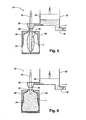
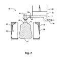
- a mold station 10 that utilizes a final liquid commodity L to impart the pressure required to expand a hot preform 12 to take on the shape of a mold thus simultaneously forming and filling the resultant container C ( FIG. 7 ).
- the mold station 10 generally includes a mold cavity 16, a pressure source 20, a blow nozzle 22 and a stretch rod 26.
- the exemplary mold cavity 16 illustrated includes mold halves 30, 32 that cooperate to define an interior surface 34 corresponding to a desired outer profile of a blown container.
- the mold cavity 16 may be moveable from an open position ( FIG. 1 ) to a closed position ( FIG. 2 ) such that a support ring 38 of the preform 12 is captured at an upper end of the mold cavity 16.
- the pressure source 20 can be in the form of, but not limited to, a filling cylinder, manifold or chamber 42 that generally includes a mechanical piston-like device 40 including, but not limited to, a piston, a pump (such as a hydraulic pump) or any other such similarly suitable device, moveable within the filling cylinder, manifold or chamber 42.
- the pressure source 20 has an inlet 46 for accepting liquid commodity L and an outlet 48 for delivering the liquid commodity L to the blow nozzle 22. It is appreciated that the inlet 46 and the outlet 48 may have valves incorporated thereat.
- the piston-like device 40 may be moveable in a first direction (upward as viewed in the figures) to draw liquid commodity L from the inlet 46 into the filling cylinder, manifold or chamber 42, and in a second direction (downward as viewed in the figures) to deliver the liquid commodity L from the filling cylinder, manifold or chamber 42 to the blow nozzle 22.
- the piston-like device 40 can be moveable by any suitable method such as pneumatically, mechanically, electrically (servo), or hydraulically for example.
- the inlet 46 of the pressure source 20 may be connected, such as by tubing or piping to a reservoir or container (not shown) which contains the final liquid commodity L. It is appreciated that the pressure source 20 may be configured differently.
- the blow nozzle 22 generally defines one or more inlets 50 for accepting the liquid commodity L from one or more outlets 48 of the pressure source 20 and an outlet 56 ( FIG. 1 ) for delivering the liquid commodity L into the preform 12. It is appreciated that the outlet 56 may define a shape complementary to the preform 12 near the support ring 38 such that the blow nozzle 22 may easily mate with the preform 12 during the forming/filling process. In one example, the blow nozzle 22 may define an opening 58 for slidably accepting the stretch rod 26 used to initiate mechanical stretching of the preform 12 in some embodiments.
- the liquid commodity L may be introduced into the plastic container C during a thermal process, typically a hot-fill process.
- bottlers generally fill the plastic container C with a liquid or product at an elevated temperature between approximately 185°F to 205°F (approximately 85°C to 96°C) and seal the plastic container C with a closure (not illustrated) before cooling.
- the liquid may be continuously circulated within the filling cylinder, manifold or chamber 42 through the inlet 46 whereby the liquid can be heated to a preset temperature (i.e., at a heat source (not illustrated) upstream of the inlet 46).
- the plastic container C may be suitable for other high-temperature pasteurization or retort filling processes, or other thermal processes as well.
- the liquid commodity L may be introduced into the plastic container C under ambient or cold temperatures. Accordingly, by way of example, the plastic container C may be filled at ambient or cold temperatures such as between approximately 32°F to 90°F (approximately 0°C to 32°C), and more preferably at approximately 40°F (approximately 4.4°C).
- mold station 10 can comprise a pressure compensation system 11 to aid in exerting a force against at least one of the mold halves 30, 32 to provide clamping force sufficient to maintain mold cavity 16 in the closed position during molding of the container.
- Pressure compensation system 10 can at least in part supplement the closing system of mold halves 30, 32 to ensure proper definition of mold cavity 16.
- the present teachings do not require such an addition. It should be recognized that according to the principles of the present teachings, high-pressure air may not be available because the liquid product or commodity L is often used for both forming and filling of the container. Alternatively, it has been found that low-pressure air may not provide sufficient clamping force during container manufacturing to produce a high-quality parting line.
- pressure compensation system 11 can comprise an isolator system 13 operably coupled to pressure source 20, a line 15 operably coupling isolator system 13 to a compensation pressure applicator 17, whereby the compensation pressure applicator 17 can exert a clamping force on at least one mold half 30, 32 in response to the pressure of the forming and filling liquids.
- the high-pressure liquids used for forming and filing of the container i.e. liquid commodity L
- the high-pressure liquids used for forming and filing of the container can be indirectly/directly used for maintaining a clamping force on the mold halves 30, 32.
- the present teachings use the final product or commodity as the forming and filling liquid, it may be desirable to employ systems or techniques to ensure the continued sterility of the liquid.
- circulation of the forming and filling liquid may be used; however, such circulation systems can increase required parts and system complexity.
- isolator system 13 can be an isolator cylinder 19 which is operable to transfer the pressure from the liquid commodity L to a separate liquid medium, hydraulic fluid or similar, L2 disposed in line 15. Separate liquid medium L2 is then operable to convey the pressure to the compensation pressure applicator 17 and create the necessary clamping force required. No additional recirculation system would be needed because the liquid commodity L would remain fluidly separate from the separate liquid medium L2.
- isolator cylinder 19 of isolator system 13 can comprise a biasing member 21 biasing isolator cylinder 19 against the fluid pressure of commodity liquid L.
- isolator system 13 can be a diaphragm member being exposed on a first side to liquid commodity L and on the other side separate liquid medium L2, thereby permitting the transfer of pressure forces without the transfer or comingling of liquids.
- Isolator system 13 can be positioned at any location within pressure compensation system 11 that is exposed to the high pressure of liquid commodity L.
- the actual pressure created by the separate liquid medium L2 for the clamping pressure can be increased by increasing the size of the isolator cylinder 19 within the isolator system 13 and/or by increasing the size/area of the compensation pressure applicator 17.
- the size of isolator system 13, line 15, and compensation pressure applicator 17 can be varied to achieve a desired pressure, or amount of compression.
- the high pressure of liquid commodity L will force the isolator cylinder 19 into the isolator system 13, thereby applying a hydraulic pressure to the separate liquid medium L2 and finally against one or more mold halves 30, 32 via compensation pressure applicator 17.
- the preform 12 may be placed into the mold cavity 16.
- a machine places the preform 12 heated to a temperature between approximately 190°F to 250°F (approximately 88°C to 121 °C) into the mold cavity 16.
- the piston-like device 40 of the pressure source 20 may begin to draw liquid commodity L into the filling cylinder, manifold or chamber 42 through the inlet 46. It should be understood that piston-like device 40 can be filled prior to this stage, if desired, or at any other suitable time.
- the mold halves 30, 32 of the mold cavity 16 may then close thereby capturing the preform 12 ( FIG. 2 ).
- the blow nozzle 22 may form a seal at the finish of the preform 12.
- the mold cavity 16 may be heated to a temperature between approximately 250°F to 350°F (approximately 93°C to 177°C) in order to impart increased crystallinity levels within the resultant container C.
- the mold cavity 16 may be provided at ambient or cold temperatures between approximately 32°F to 90°F (approximately 0°C to 32°C).
- Liquid commodity L may continue to be drawn into the filling cylinder, manifold or chamber 42 by the piston-like device 40.
- the stretch rod 26 may extend into the preform 12 to initiate mechanical stretching in some embodiments.
- the liquid commodity L may continue to be drawn into the filling cylinder, manifold or chamber 42.
- the stretch rod 26 continues to stretch the preform 12 thereby thinning the sidewalls of the preform 12.
- the volume of liquid commodity L in the filling cylinder, manifold or chamber 42 may increase until the appropriate volume suitable to form and fill the resultant container C is reached.
- a valve disposed at the inlet 46 of the pressure source 20 may be closed.
- the piston-like device 40 may begin to drive downward (drive phase) to initiate the rapid transfer of liquid commodity L from the filling cylinder, manifold or chamber 42 to the preform 12.
- the piston-like device 40 may be actuated by any suitable means such as pneumatic, mechanical, electrical (servo), and/or hydraulic pressure.
- the hydraulic pressure within the preform 12 may reach between approximately 100 PSI to 1000 PSI.
- the liquid commodity L causes the preform 12 to expand toward the interior surface 34 of the mold cavity 16.
- FIG. 1 As described herein and illustrated in FIG.
- pressure compensation system 11 can be used to exert a clamping force on at least one of mold halves 30, 32 by directly or indirectly transferring the pressure force of liquid commodity L to a separate liquid medium L2 (in some embodiments) that drives a compensation pressure applicator 17 against one or more mold halves 30,32.
- Residual air may be vented through a passage 70 defined in the stretch rod 26 ( FIG. 5 ).
- the piston-like device 40 has completed its drive phase thereby completely transferring the appropriate volume of liquid commodity L to the newly formed plastic container C.
- the stretch rod 26 may be withdrawn from the mold cavity 16 while continuing to vent residual air.
- the stretch rod 26 may be designed to displace a predetermined volume of liquid commodity L when it is withdrawn from the mold cavity 16 thereby allowing for the desired fill level of liquid commodity L within the resultant plastic container C and/or the desired headspace.
- the desired fill level and/or headspace will correspond between the level of the support ring 38 and the mid-shoulder area of the plastic container C.
- liquid commodity L can be provided at a constant pressure or at different pressures during the molding cycle.
- liquid commodity L may be provided at a pressure which is less than the pressure applied when the preform 12 is blown into substantial conformity with the interior surface 34 of the mold cavity 16 defining the final configuration of the plastic container C.
- This lower pressure P 1 may be ambient or greater than ambient but less than the subsequent high pressure P 2 .
- the preform 12 is axially stretched in the mold cavity 16 to a length approximating the final length of the resultant plastic container C. During or just after stretching the preform 12, the preform 12 is generally expanded radially outward under the low pressure P 1 .
- This low pressure P 1 is preferably in the range of between approximately 100 PSI to 150 PSI and can be held for a predetermined amount of time, such as 0.1 to 0.2 seconds.
- the preform 12 is further expanded under the high pressure P 2 such that the preform 12 contacts the interior surface 34 of the mold halves 30, 32 thereby forming the resultant plastic container C.
- the high pressure P 2 is in the range of approximately 400 PSI to 600 PSI and can be held for a predetermined amount of time, such as 0.1 to 0.2 seconds.
- more than one piston-like device may be employed during the formation of the resultant plastic container C.
- a primary piston-like device may be used to generate the low pressure P 1 to initially expand the preform 12 while a secondary piston-like device may be used to generate the subsequent high pressure P 2 to further expand the preform 12 such that the preform 12 contacts the interior surface 34 of the mold halves 30, 32 thereby forming the resultant plastic container C.
- the fill cycle is shown completed.
- the mold halves 30, 32 may separate and the blow nozzle 22 may be withdrawn.
- the resultant filled plastic container C is now ready for post-forming steps such as capping, cooling (if necessary), labeling and packing.
- the piston-like device 40 may begin the next cycle by drawing liquid commodity L through the inlet 46 of the pressure source 20 in preparation for the next fill/form cycle.
- the mold station 10 may include a controller for communicating signals to the various components. In this way, components such as, but not limited to, the mold cavity 16, the blow nozzle 22, the stretch rod 26, the piston-like device 40 and various valves may operate according to a signal communicated by the controller. It is also contemplated that the controller may be utilized to adjust various parameters associated with these components according to a given application.
- a movable filling cylinder, manifold, or chamber may not provide sufficient space optimization or facility efficiency. Moreover, in some embodiments, it may be difficult to obtain and/or route pressurized fluid from a first location to the preform shaping location.
- the pressure source 20 can be in the form of a servo system 60 that generally includes one or more servo motors 62 being actuated by one or more controllers 64 via a line 66.
- the servo system 60 can be positioned adjacent to the preform shaping location.
- the servo system 60 can comprise inlet 46 for accepting liquid commodity L and outlet 48 for delivering the liquid commodity L to the blow nozzle 22.
- the servo motor 62 may be operable in a first direction to draw liquid commodity L from the inlet 46 and output the liquid commodity L from the outlet 48 to the blow nozzle 22 (i.e. forward flow).
- the servo motor 62 in some embodiments, may also be operable in a second direction to draw liquid commodity L from outlet 48, blow nozzle 22, and/or preform 12 (i.e. reverse flow), which will be discussed in greater detail herein.
- servo motor 62 can be used to overcome some of the difficulties in metering precise and/or minute quantities of commodity L. That is, servo motor 62 is precisely and variably controlled to permit precise metering of a through flow of commodity L and at a variable rate.
- This precise and variably control can be coupled with a feedback loop to provide active and real-time monitoring and control of the fill process, including stopping of the filling process in the event of a detected issue, such as a blow-out.
- the feedback loop can be formed as part of controller 64, with appropriate sensors disposed at any one of a number of locations provide sufficient data to detect a relevant parameter (e.g. pressure sensors, flow sensors, shape sensors, and the like). Because active control of the pressures and quantity of flow of commodity L is often important to the final formed product, the use of servo system 60 is particularly well suited to provide such benefits.
- servo system 60 may require less electrical power to operate, thereby providing additional benefits in terms of reduced electrical consumption and cost. That is, it has been found that servo system 60 uses merely 10% of the electricity required for a similar high pressure air system.
- the method described herein may be particularly useful for filling applications such as isotonic, juice, tea and other commodities that are susceptible to biological contamination. As such, these commodities are typically filled in a controlled, sterile environment. Commercially, two ways are typically used to achieve the required sterile environment. In Europe, one primary method for filling these types of beverages is in an aseptic filling environment. The filling operation is performed in a clean room. All of the components of the product including the packaging must be sterilized prior to filling. Once filled, the product may be sealed until it is consumed preventing any potential for the introduction of bacteria. The process is expensive to install and operate. As well, there is always the risk of a bacterial contaminant breaking through the operational defenses and contaminating the product.
Landscapes
- Engineering & Computer Science (AREA)
- Mechanical Engineering (AREA)
- Manufacturing & Machinery (AREA)
- Blow-Moulding Or Thermoforming Of Plastics Or The Like (AREA)
- Moulds For Moulding Plastics Or The Like (AREA)
- Containers Having Bodies Formed In One Piece (AREA)
- Basic Packing Technique (AREA)
Claims (13)
- Système pour former et remplir simultanément un contenant comprenant :un moule comportant une cavité de moule (16) définissant une surface interne (34) et conçu pour accepter une préforme (12) ;une source de pression (20) poussant un premier liquide vers la préforme ;une soufflette (22) conçue pour recevoir le premier liquide de la source de pression (20) et pour transférer le premier liquide à une pression ou un volume dans la préforme (12), poussant de ce fait la préforme (12) à s'étendre vers la surface interne (34) de la cavité de moule (16) et à créer un contenant résultant, dans lequel le premier liquide reste dans le contenant en tant que produit final ;le système étant caractérisé en ce qu'il comprend en outre :un système de compensation de pression (11) exerçant une force de serrage sur ledit moule en réponse à ladite source de pression,dans lequel ledit système de compensation de pression (11) comprend :un applicateur de pression de compensation (17) venant en prise fonctionnellement avec ledit moule pour exercer ladite force de serrage ; etun système d'isolement (13), couplé fonctionnellement à ladite source de pression (20) pour transférer une pression du premier liquide à une conduite (15) couplée au dit applicateur de pression de compensation (17),dans lequel ledit système d'isolement (13) comprend un cylindre d'isolement (19) transférant ladite pression du premier liquide à un deuxième liquide disposé dans ladite conduite (15), ledit premier liquide étant isolé fluidiquement dudit deuxième liquide, ou dans lequel ledit système d'isolement (13) comprend une membrane transférant ladite pression du premier liquide à un deuxième liquide disposé dans ladite conduite (15), ledit premier liquide étant isolé fluidiquement dudit deuxième liquide.
- Système pour former et remplir simultanément un contenant selon la revendication 1, dans lequel ledit cylindre d'isolement (19) est sollicité par ressort contre ladite pression de ladite source de pression (20).
- Système pour former et remplir simultanément un contenant selon la revendication 1 ou 2, comprenant en outre un système de servomoteur (60) comprenant au moins un servomoteur (62), et un contrôleur (64), dans lequel ledit au moins un servomoteur (62) est commandé de manière variable.
- Système pour former et remplir simultanément un contenant selon l'une quelconque des revendications 1 à 3, dans lequel le premier liquide est transféré dans la préforme (12) pendant un processus de remplissage à chaud, le premier liquide étant à une température comprise entre environ 85 °C et 96 °C.
- Système pour former et remplir simultanément un contenant selon l'une quelconque des revendications 1 à 4, dans lequel le premier liquide est transféré dans la préforme (12) à une température ambiante, le premier liquide étant à une température comprise entre environ 0 °C et 32 °C.
- Système pour former et remplir simultanément un contenant selon l'une quelconque des revendications 1 à 5, dans lequel la cavité de moule (16) accepte une préforme (12) chauffée à une température comprise entre environ 88 °C et 121 °C.
- Système pour former et remplir simultanément un contenant selon l'une quelconque des revendications 1 à 6, dans lequel la cavité de moule (16) est chauffée à une température comprise entre environ 93 °C et 177 °C.
- Système pour former et remplir simultanément un contenant selon l'une quelconque des revendications 1 à 7, dans lequel la cavité de moule est à une température comprise entre environ 0 °C et 32 °C.
- Système pour former et remplir simultanément un contenant selon l'une quelconque des revendications 1 à 8, dans lequel le premier liquide est transféré dans la préforme (12) à une pression comprise entre environ 6,8 bars (100 PSI) et 41,4 bars (600 PSI).
- Système pour former et remplir simultanément un contenant selon l'une quelconque des revendications 1 à 9, comprenant en outre une tige d'élargissement (26) conçue pour s'étendre dans la préforme (12) et étendre mécaniquement la préforme (12) avant que le premier liquide soit poussé dans la préforme.
- Système pour former et remplir simultanément un contenant selon la revendication 10, dans lequel la tige d'élargissement (26) est reliée à l'air extérieur.
- Système pour former et remplir simultanément un contenant selon l'une quelconque des revendications 1 à 11, dans lequel la préforme (12) est initialement étendue vers l'extérieur sous une première pression et étendue par la suite vers l'extérieur sous une deuxième pression, la deuxième pression étant supérieure à la première pression.
- Système pour former et remplir simultanément un contenant selon la revendication 12, dans lequel la première pression est comprise entre environ 6,8 bars (100 PSI) et 10,4 bars (150 PSI) et la deuxième pression est comprise entre environ 27,5 bars (400 PSI) et 41,4 bars (600 PSI).
Applications Claiming Priority (3)
| Application Number | Priority Date | Filing Date | Title |
|---|---|---|---|
| US201161495072P | 2011-06-09 | 2011-06-09 | |
| US13/489,943 US9216537B2 (en) | 2011-06-09 | 2012-06-06 | Compensation for hydrapak machine using isolator cylinder |
| PCT/US2012/041084 WO2012170517A2 (fr) | 2011-06-09 | 2012-06-06 | Compensation pour machines à hydrapaks utilisant un cylindre isolateur |
Publications (3)
| Publication Number | Publication Date |
|---|---|
| EP2694271A2 EP2694271A2 (fr) | 2014-02-12 |
| EP2694271A4 EP2694271A4 (fr) | 2014-02-19 |
| EP2694271B1 true EP2694271B1 (fr) | 2015-10-21 |
Family
ID=47293396
Family Applications (1)
| Application Number | Title | Priority Date | Filing Date |
|---|---|---|---|
| EP12797531.6A Active EP2694271B1 (fr) | 2011-06-09 | 2012-06-06 | Système |
Country Status (8)
| Country | Link |
|---|---|
| US (1) | US9216537B2 (fr) |
| EP (1) | EP2694271B1 (fr) |
| JP (1) | JP5977341B2 (fr) |
| CN (1) | CN103608164B (fr) |
| AR (1) | AR086891A1 (fr) |
| BR (1) | BR112013031386B1 (fr) |
| MX (1) | MX2013014167A (fr) |
| WO (1) | WO2012170517A2 (fr) |
Families Citing this family (18)
| Publication number | Priority date | Publication date | Assignee | Title |
|---|---|---|---|---|
| FR2988637B1 (fr) * | 2012-04-02 | 2014-05-09 | Sidel Participations | Machine de formage comportant une conduite de communication entre une chambre de compensation et une tuyere |
| EP2801470B1 (fr) | 2013-05-07 | 2017-10-04 | Discma AG | Appareil et procédé de fabrication des récipients |
| EP2801469A1 (fr) | 2013-05-07 | 2014-11-12 | Nestec S.A. | Appareil et procédé de fabrication des récipients |
| EP2801468B1 (fr) * | 2013-05-07 | 2018-02-28 | Discma AG | Appareil et procédé de fabrication des récipients |
| US10046505B2 (en) | 2013-06-28 | 2018-08-14 | Discma Ag | Method of molding a container |
| JP6122762B2 (ja) * | 2013-10-31 | 2017-04-26 | 株式会社吉野工業所 | ブロー成形装置 |
| EP2883800B1 (fr) * | 2013-12-13 | 2017-08-16 | Discma AG | Dispositif de piston comprenant une vanne de régulation de l'entrée dudit dispositif |
| EP2883681B1 (fr) | 2013-12-16 | 2018-09-12 | Discma AG | Pluralité de récipients et emballage comprenant une pluralité de récipients |
| WO2015136368A2 (fr) * | 2014-03-10 | 2015-09-17 | Discma Ag | Procédé de formation et de réglage de l'espace libre dans un récipient |
| DE102014019400A1 (de) * | 2014-12-31 | 2016-06-30 | Khs Corpoplast Gmbh | Verfahren zum Herstellen von mit einem flüssigen Füllgut gefüllten Behältern aus Vorformlingen aus einem thermoplastischen Material sowie eine Vorrichtung hierfür |
| JP6632872B2 (ja) * | 2015-11-27 | 2020-01-22 | 株式会社吉野工業所 | 液体ブロー成形方法 |
| JP6685705B2 (ja) * | 2015-11-27 | 2020-04-22 | 株式会社吉野工業所 | 液体ブロー成形方法及び液体ブロー成形装置 |
| JP6605312B2 (ja) * | 2015-11-27 | 2019-11-13 | 株式会社吉野工業所 | 液体ブロー成形方法 |
| CA3088197C (fr) | 2018-01-11 | 2023-06-20 | Husky Injection Molding Systems Ltd. | Procede et appareil pour donner une forme finale a des contenants en utilisant un liquide devant etre contenu dans lesdits contenants |
| IT201800001700A1 (it) * | 2018-01-23 | 2019-07-23 | Gea Procomac Spa | Apparato e processo di formatura in asettico di contenitori a partire da preforme in materiale termoplastico |
| CN114080315B (zh) * | 2019-06-27 | 2024-04-23 | 帝斯克玛股份有限公司 | 形成并填充容器的高压工艺及对应系统 |
| EP3990251B1 (fr) * | 2019-06-27 | 2024-11-06 | Discma AG | Amortissement lors de la formation et du remplissage d'un récipient |
| EP3990252B1 (fr) * | 2019-06-28 | 2024-08-21 | Discma AG | Récipient pour matériau réduit et système et méthode de formation associés |
Family Cites Families (79)
| Publication number | Priority date | Publication date | Assignee | Title |
|---|---|---|---|---|
| US3267185A (en) | 1962-12-31 | 1966-08-16 | Union Oil Co | Method and apparatus for forming and filling hollow plastic articles |
| US3268635A (en) | 1963-02-25 | 1966-08-23 | Robert A Kraus | Arrangement for forming foam plastic article |
| US3993427A (en) | 1974-10-11 | 1976-11-23 | Monsanto Company | Movable preform locator and blow air valve apparatus for a blow molding machine |
| GB1474044A (en) | 1974-12-03 | 1977-05-18 | Ici Ltd | Plastics container manufacture |
| DE2717365A1 (de) | 1977-04-20 | 1978-10-26 | Bekum Maschf Gmbh | Verfahren zur herstellung von hohlkoerpern aus thermoplastischem kunststoff |
| DE2927617A1 (de) | 1979-07-07 | 1981-01-08 | Cillichemie | Dosiervorrichtung |
| JPS57123027A (en) | 1981-01-26 | 1982-07-31 | Pentel Kk | Method of blow molding plastic container filled with paste such as color |
| US4432720A (en) | 1981-04-24 | 1984-02-21 | Cincinnati Milacron Inc. | Apparatus for high rate production of biaxially oriented thermoplastic articles |
| US4457688A (en) | 1981-05-07 | 1984-07-03 | Cincinnati Milacron Inc. | External center pin for blow molding machine |
| FR2510940A1 (fr) | 1981-08-06 | 1983-02-11 | Solvay | Procede et appareillage pour la fabrication de tuyaux en matiere plastique orientee moleculaire |
| US4490327A (en) | 1982-02-03 | 1984-12-25 | Cincinnati Milacron Industries, Inc. | External center pin for blow molding machine |
| JPS59184623A (ja) * | 1983-04-04 | 1984-10-20 | Japan Steel Works Ltd:The | 中空成形機のサ−ボ制御装置 |
| US4539172A (en) | 1983-12-16 | 1985-09-03 | Baxter Travenol Laboratories, Inc. | Method of blowmolding a container having an integral inner dispensing outlet |
| US4725464A (en) | 1986-05-30 | 1988-02-16 | Continental Pet Technologies, Inc. | Refillable polyester beverage bottle and preform for forming same |
| US4883631A (en) | 1986-09-22 | 1989-11-28 | Owens-Illinois Plastic Products Inc. | Heat set method for oval containers |
| JPS63249616A (ja) | 1987-04-07 | 1988-10-17 | Komatsu Ltd | 樹脂成形方法 |
| US4935190A (en) | 1987-07-10 | 1990-06-19 | William G. Whitney | Method of making balloon retention catheter |
| US5352402A (en) | 1989-10-23 | 1994-10-04 | Nissei Asb Machine Co., Ltd. | Method and apparatus for manufacturing biaxially oriented, thermally stable, blown containers |
| DE69026793D1 (de) | 1989-11-16 | 1996-06-05 | Mitsui Petrochemical Ind | Behälter mit einem Aufhängegriff und Verfahren zu seiner Herstellung |
| US5066528A (en) | 1990-03-05 | 1991-11-19 | Continental Pet Technologies, Inc. | Refillable polyester container and preform for forming the same |
| FR2659265B1 (fr) | 1990-03-06 | 1992-06-26 | Sidel Sa | Procede de dispositif pour fabriquer des recipients en matieres thermoplastiques par soufflage ou etirage-soufflage. |
| JPH0675911B2 (ja) | 1990-08-14 | 1994-09-28 | 日精エー・エス・ビー機械株式会社 | 広口容器の延伸吹込成形方法及び装置 |
| JPH0813498B2 (ja) | 1992-02-29 | 1996-02-14 | 日精エー・エス・ビー機械株式会社 | 耐熱性容器の成形方法 |
| US5344596A (en) | 1992-03-23 | 1994-09-06 | Icp Systems, Inc. | Method for fluid compression of injection molded plastic material |
| US5269672A (en) | 1992-06-29 | 1993-12-14 | Hoover Universal, Inc. | Servo stretch assembly for blow molding machine |
| US5478229A (en) | 1993-01-29 | 1995-12-26 | The Japan Steel Works, Ltd. | Apparatus for forming hollow article |
| JP3528132B2 (ja) * | 1993-06-04 | 2004-05-17 | 義勝 河野 | ブロー成形法 |
| US5474735A (en) | 1993-09-24 | 1995-12-12 | Continental Pet Technologies, Inc. | Pulse blow method for forming container with enhanced thermal stability |
| US5486103A (en) * | 1994-05-09 | 1996-01-23 | Electra Form, Inc. | Blow mold clamp assembly |
| US5635226A (en) | 1994-09-26 | 1997-06-03 | A.K. Technical Laboratory Inc. | Composite molding device for stretch blow molding |
| DE4439231C1 (de) | 1994-11-03 | 1996-04-25 | Bernd Hansen | Blasformverfahren zum Herstellen eines verschlossenen Behältnisses und nach diesem Verfahren hergestelltes Behältnis |
| KR0147442B1 (ko) | 1994-11-15 | 1998-08-17 | 성재갑 | 주입식 금형 |
| DE4441815C2 (de) | 1994-11-24 | 1997-09-18 | Tuhh Tech Gmbh | Verfahren und Vorrichtung zur Herstellung von Kunststoffteilen |
| US6214282B1 (en) | 1995-08-23 | 2001-04-10 | The Japan Steel Works, Ltd. | Simultaneous filling blow molding method and apparatus |
| US5962039A (en) | 1997-02-21 | 1999-10-05 | The Japan Steel Works, Ltd. | Simultaneous filling blow molding apparatus |
| JPH0999477A (ja) | 1995-10-06 | 1997-04-15 | Japan Steel Works Ltd:The | 同時充填中空成形方法およびその装置 |
| JPH0957834A (ja) | 1995-08-23 | 1997-03-04 | Japan Steel Works Ltd:The | 同時充填中空成形機の液体充填方法およびその装置 |
| JP2984228B2 (ja) | 1996-12-05 | 1999-11-29 | 東海ゴム工業株式会社 | エポキシ樹脂成形用金型 |
| US5845667A (en) | 1996-12-19 | 1998-12-08 | Saturn Electronics & Engineering, Inc. | Single stage variable force solenoid pressure regulating valve |
| SE511861C2 (sv) | 1998-04-07 | 1999-12-06 | Tetra Laval Holdings & Finance | Sätt och anordning för att framställa en steril förpackningsbehållare |
| US6277321B1 (en) | 1998-04-09 | 2001-08-21 | Schmalbach-Lubeca Ag | Method of forming wide-mouth, heat-set, pinch-grip containers |
| CA2239192C (fr) * | 1998-05-29 | 2007-07-24 | Wentworth Mould And Die Company Limited | Porte-moules universel muni d'une compensation d'ecoulement d'air amelioree |
| JP2000043129A (ja) | 1998-07-29 | 2000-02-15 | Ishikawajima Harima Heavy Ind Co Ltd | プラスチック容器の成形方法 |
| DE19929033B4 (de) | 1999-06-25 | 2009-05-07 | Khs Corpoplast Gmbh & Co. Kg | Vorrichtung zur Blasformung von Behältern |
| US6485669B1 (en) | 1999-09-14 | 2002-11-26 | Schmalbach-Lubeca Ag | Blow molding method for producing pasteurizable containers |
| US6485670B1 (en) | 1999-11-09 | 2002-11-26 | Schmalbach-Lubeca Ag | Blow molding method for producing pasteurizable containers |
| EP1155807B1 (fr) | 1999-11-30 | 2005-02-09 | Yoshino Kogyosho Co., Ltd. | Procédé de moulage d'un récipient multicouche en polyester |
| JP2001199412A (ja) * | 2000-01-14 | 2001-07-24 | Toyo Jidoki Co Ltd | 液状物の充填装置及び充填方法 |
| JP2001212874A (ja) | 2000-02-02 | 2001-08-07 | Shikoku Kakoki Co Ltd | 無菌容器成形充填方法 |
| FR2813231B1 (fr) | 2000-08-31 | 2003-05-09 | Sidel Sa | Unite de moulage comportant une chambre de compensation delimitee par une membrane, membrane pour une telle unite et machine munie d'une telle unite |
| JP2002067135A (ja) * | 2000-09-01 | 2002-03-05 | Placo Co Ltd | ブロー成形方法とその装置 |
| FR2814392B1 (fr) | 2000-09-25 | 2002-12-20 | Sidel Sa | Machine d'etirage-soufflage comportant une commande perfectionnee de la tige d'etirage |
| US6502369B1 (en) | 2000-10-25 | 2003-01-07 | Amcor Twinpak-North America Inc. | Method of supporting plastic containers during product filling and packaging when exposed to elevated temperatures and internal pressure variations |
| US7141190B2 (en) | 2001-11-27 | 2006-11-28 | Hekal Ihab M | Biaxially oriented hollow thermoplastic bodies and improved method for sterilization |
| FR2839277B1 (fr) | 2002-05-03 | 2005-04-08 | Nestle Waters Man & Technology | Procede de fabrication d'un contenant en resine polyester et dispositif pour sa mise en oeuvre |
| FR2848906B1 (fr) | 2002-12-23 | 2006-08-18 | Sidel Sa | Procede et installation de fabrication d'un recipient en matiere plastique |
| EP1636289B1 (fr) | 2003-06-18 | 2009-09-16 | The Coca-Cola Company | Procede de remplissage a chaud de contenants faits a partir de compositions a base de polyester |
| US20050067002A1 (en) | 2003-09-25 | 2005-03-31 | Supercritical Systems, Inc. | Processing chamber including a circulation loop integrally formed in a chamber housing |
| ATE423670T1 (de) | 2003-11-06 | 2009-03-15 | Nestle Waters Man & Technology | Herstellungsverfahren von behältern aus polyesterharz |
| FR2863930B1 (fr) | 2003-12-19 | 2006-03-03 | Sidel Sa | Dispositif de moulage pour la fabrication de recipients en materiau thermoplastique |
| JP4335040B2 (ja) | 2004-03-15 | 2009-09-30 | 株式会社フロンティア | プラスチック容器のブロー成形方法 |
| ITPN20040021A1 (it) | 2004-03-19 | 2004-06-19 | Servizi Tecnici Avanzati S R L | "impianto di riempimento di bottiglie con valvola di riempimento perfezionata" |
| EP1688234A3 (fr) | 2005-02-04 | 2006-10-11 | The Procter & Gamble Company | Procédé de fabrication d'un récipient par moulage par étirage-soufflage et récipient ainsi fabriqué |
| US7981356B2 (en) | 2005-03-15 | 2011-07-19 | Invoplas Pty Ltd | Stretch blow moulding method and apparatus |
| US20060231646A1 (en) | 2005-04-18 | 2006-10-19 | Geary Charles T Jr | Straight flow nozzle |
| NL1028904C2 (nl) * | 2005-04-29 | 2006-10-31 | Fico Bv | Pers met plaatvormige gesteldelen, en werkwijze voor het bedrijven van een dergelijke platenpers. |
| FR2887525B1 (fr) | 2005-06-24 | 2007-09-07 | Sidel Sas | Installation produisant des bouteilles steriles par soufflage a partir de preformes sterilisees |
| US7621465B2 (en) | 2005-11-10 | 2009-11-24 | Nordson Corporation | Air annulus cut off nozzle to reduce stringing and method |
| DE102006002632A1 (de) * | 2006-01-19 | 2007-07-26 | Khs Ag | Verfahren zum Herstellen von Flaschen oder dergleichen Behältern aus Kunststoff durch Blasen sowie nach diesem Verfahren hergestellte Flaschen oder dergleichen Behälter |
| US7914726B2 (en) * | 2006-04-13 | 2011-03-29 | Amcor Limited | Liquid or hydraulic blow molding |
| FR2903933B1 (fr) | 2006-07-21 | 2008-10-03 | Sidel Participations | Dispositif de moulage pour la fabrication de recipients thermoplastiques |
| JP5026813B2 (ja) * | 2007-02-16 | 2012-09-19 | 四国化工機株式会社 | 定量充填装置 |
| ITVI20070100A1 (it) | 2007-04-03 | 2008-10-04 | Gruppo Bertolaso Spa | Apparecchiatura perfezionata per il riempimento di contenitori |
| FR2914876B1 (fr) | 2007-04-10 | 2009-07-10 | Sidel Participations | Dispositif de moulage, par soufflage ou etirage-soufflage, de recipients en matiere thermoplastique |
| FR2918916B1 (fr) | 2007-07-19 | 2009-10-23 | Sidel Participations | Installation pour la fabrication de recipients a partir d'une preforme et procede de commande des moyens de soufflage d'une telle installation |
| US8017064B2 (en) * | 2007-12-06 | 2011-09-13 | Amcor Limited | Liquid or hydraulic blow molding |
| EP2143543A1 (fr) | 2008-07-07 | 2010-01-13 | Nestec S.A. | Dispositif et procédé de conditionnement de liquide alimentaire |
| US8439281B2 (en) | 2008-08-15 | 2013-05-14 | Hyde Tools, Inc. | Modular coatings sprayer |
| DE102009023406A1 (de) | 2009-05-29 | 2010-12-02 | Krones Ag | Blasmaschine mit CIP-Reinigungssystem zur Herstellung von Kunststoff-Flaschen, insbesondere PET-Flaschen |
-
2012
- 2012-06-06 US US13/489,943 patent/US9216537B2/en active Active
- 2012-06-06 EP EP12797531.6A patent/EP2694271B1/fr active Active
- 2012-06-06 MX MX2013014167A patent/MX2013014167A/es active IP Right Grant
- 2012-06-06 CN CN201280028182.2A patent/CN103608164B/zh active Active
- 2012-06-06 BR BR112013031386-2A patent/BR112013031386B1/pt active IP Right Grant
- 2012-06-06 JP JP2014514586A patent/JP5977341B2/ja active Active
- 2012-06-06 WO PCT/US2012/041084 patent/WO2012170517A2/fr not_active Ceased
- 2012-06-08 AR ARP120102057A patent/AR086891A1/es active IP Right Grant
Also Published As
| Publication number | Publication date |
|---|---|
| MX2013014167A (es) | 2014-06-23 |
| JP5977341B2 (ja) | 2016-08-24 |
| JP2014519429A (ja) | 2014-08-14 |
| CN103608164A (zh) | 2014-02-26 |
| BR112013031386A2 (pt) | 2017-06-27 |
| CN103608164B (zh) | 2015-12-02 |
| BR112013031386B1 (pt) | 2021-02-09 |
| WO2012170517A2 (fr) | 2012-12-13 |
| WO2012170517A3 (fr) | 2013-04-25 |
| AR086891A1 (es) | 2014-01-29 |
| US20120315348A1 (en) | 2012-12-13 |
| EP2694271A4 (fr) | 2014-02-19 |
| US9216537B2 (en) | 2015-12-22 |
| EP2694271A2 (fr) | 2014-02-12 |
Similar Documents
| Publication | Publication Date | Title |
|---|---|---|
| EP2694271B1 (fr) | Système | |
| US9669578B2 (en) | Method and apparatus for forming and filling a container | |
| EP2629956B1 (fr) | Système de formage et de remplissage d'un récipient moulé par soufflage | |
| EP2010369B1 (fr) | Moulage par soufflage par liquide ou hydraulique | |
| US8017064B2 (en) | Liquid or hydraulic blow molding | |
| US20130147097A1 (en) | Method for forming a preform for a container | |
| EP2697121B1 (fr) | Refroidissement et pressurisation de csd pour maintenir du co2 en solution pendant le formage | |
| EP3645239B1 (fr) | Procédé de moulage par soufflage avec un liquide | |
| EP2771168B1 (fr) | Procédé et appareil pour former et remplir un récipient |
Legal Events
| Date | Code | Title | Description |
|---|---|---|---|
| PUAI | Public reference made under article 153(3) epc to a published international application that has entered the european phase |
Free format text: ORIGINAL CODE: 0009012 |
|
| 17P | Request for examination filed |
Effective date: 20131018 |
|
| AK | Designated contracting states |
Kind code of ref document: A2 Designated state(s): AL AT BE BG CH CY CZ DE DK EE ES FI FR GB GR HR HU IE IS IT LI LT LU LV MC MK MT NL NO PL PT RO RS SE SI SK SM TR |
|
| A4 | Supplementary search report drawn up and despatched |
Effective date: 20140121 |
|
| RIC1 | Information provided on ipc code assigned before grant |
Ipc: B29K 67/00 20060101ALN20140115BHEP Ipc: B29C 49/56 20060101ALI20140115BHEP Ipc: B29C 49/58 20060101ALN20140115BHEP Ipc: B29C 49/46 20060101ALI20140115BHEP Ipc: B67D 3/02 20060101ALI20140115BHEP Ipc: B65B 3/04 20060101AFI20140115BHEP Ipc: B29K 23/00 20060101ALN20140115BHEP Ipc: B29C 49/78 20060101ALN20140115BHEP Ipc: B29C 49/12 20060101ALN20140115BHEP |
|
| RAP1 | Party data changed (applicant data changed or rights of an application transferred) |
Owner name: DISCMA AG |
|
| DAX | Request for extension of the european patent (deleted) | ||
| GRAP | Despatch of communication of intention to grant a patent |
Free format text: ORIGINAL CODE: EPIDOSNIGR1 |
|
| RIC1 | Information provided on ipc code assigned before grant |
Ipc: B29C 49/58 20060101ALN20141128BHEP Ipc: B29C 49/56 20060101ALI20141128BHEP Ipc: B29C 49/78 20060101ALN20141128BHEP Ipc: B29K 23/00 20060101ALN20141128BHEP Ipc: B29C 49/12 20060101ALN20141128BHEP Ipc: B67D 3/02 20060101ALI20141128BHEP Ipc: B29K 67/00 20060101ALN20141128BHEP Ipc: B65B 3/04 20060101AFI20141128BHEP Ipc: B29C 49/46 20060101ALI20141128BHEP |
|
| INTG | Intention to grant announced |
Effective date: 20150105 |
|
| REG | Reference to a national code |
Ref country code: DE Ref legal event code: R079 Ref document number: 602012011893 Country of ref document: DE Free format text: PREVIOUS MAIN CLASS: B29C0049420000 Ipc: B65B0003040000 |
|
| GRAP | Despatch of communication of intention to grant a patent |
Free format text: ORIGINAL CODE: EPIDOSNIGR1 |
|
| INTG | Intention to grant announced |
Effective date: 20150518 |
|
| RIC1 | Information provided on ipc code assigned before grant |
Ipc: B29C 49/12 20060101ALN20150504BHEP Ipc: B29K 23/00 20060101ALN20150504BHEP Ipc: B29C 49/46 20060101ALI20150504BHEP Ipc: B65B 3/04 20060101AFI20150504BHEP Ipc: B29C 49/58 20060101ALN20150504BHEP Ipc: B29C 49/78 20060101ALN20150504BHEP Ipc: B29K 67/00 20060101ALN20150504BHEP Ipc: B29C 49/56 20060101ALI20150504BHEP Ipc: B67D 3/02 20060101ALI20150504BHEP |
|
| GRAS | Grant fee paid |
Free format text: ORIGINAL CODE: EPIDOSNIGR3 |
|
| GRAA | (expected) grant |
Free format text: ORIGINAL CODE: 0009210 |
|
| AK | Designated contracting states |
Kind code of ref document: B1 Designated state(s): AL AT BE BG CH CY CZ DE DK EE ES FI FR GB GR HR HU IE IS IT LI LT LU LV MC MK MT NL NO PL PT RO RS SE SI SK SM TR |
|
| REG | Reference to a national code |
Ref country code: GB Ref legal event code: FG4D Ref country code: NL Ref legal event code: MP Effective date: 20151021 |
|
| REG | Reference to a national code |
Ref country code: CH Ref legal event code: EP |
|
| REG | Reference to a national code |
Ref country code: CH Ref legal event code: NV Representative=s name: ARNOLD AND SIEDSMA AG, CH |
|
| REG | Reference to a national code |
Ref country code: AT Ref legal event code: REF Ref document number: 756430 Country of ref document: AT Kind code of ref document: T Effective date: 20151115 |
|
| REG | Reference to a national code |
Ref country code: IE Ref legal event code: FG4D |
|
| REG | Reference to a national code |
Ref country code: DE Ref legal event code: R096 Ref document number: 602012011893 Country of ref document: DE |
|
| REG | Reference to a national code |
Ref country code: LT Ref legal event code: MG4D |
|
| REG | Reference to a national code |
Ref country code: AT Ref legal event code: MK05 Ref document number: 756430 Country of ref document: AT Kind code of ref document: T Effective date: 20151021 |
|
| PG25 | Lapsed in a contracting state [announced via postgrant information from national office to epo] |
Ref country code: LT Free format text: LAPSE BECAUSE OF FAILURE TO SUBMIT A TRANSLATION OF THE DESCRIPTION OR TO PAY THE FEE WITHIN THE PRESCRIBED TIME-LIMIT Effective date: 20151021 Ref country code: NL Free format text: LAPSE BECAUSE OF FAILURE TO SUBMIT A TRANSLATION OF THE DESCRIPTION OR TO PAY THE FEE WITHIN THE PRESCRIBED TIME-LIMIT Effective date: 20151021 Ref country code: IS Free format text: LAPSE BECAUSE OF FAILURE TO SUBMIT A TRANSLATION OF THE DESCRIPTION OR TO PAY THE FEE WITHIN THE PRESCRIBED TIME-LIMIT Effective date: 20160221 Ref country code: ES Free format text: LAPSE BECAUSE OF FAILURE TO SUBMIT A TRANSLATION OF THE DESCRIPTION OR TO PAY THE FEE WITHIN THE PRESCRIBED TIME-LIMIT Effective date: 20151021 Ref country code: HR Free format text: LAPSE BECAUSE OF FAILURE TO SUBMIT A TRANSLATION OF THE DESCRIPTION OR TO PAY THE FEE WITHIN THE PRESCRIBED TIME-LIMIT Effective date: 20151021 Ref country code: NO Free format text: LAPSE BECAUSE OF FAILURE TO SUBMIT A TRANSLATION OF THE DESCRIPTION OR TO PAY THE FEE WITHIN THE PRESCRIBED TIME-LIMIT Effective date: 20160121 |
|
| REG | Reference to a national code |
Ref country code: FR Ref legal event code: PLFP Year of fee payment: 5 |
|
| PG25 | Lapsed in a contracting state [announced via postgrant information from national office to epo] |
Ref country code: PT Free format text: LAPSE BECAUSE OF FAILURE TO SUBMIT A TRANSLATION OF THE DESCRIPTION OR TO PAY THE FEE WITHIN THE PRESCRIBED TIME-LIMIT Effective date: 20160222 Ref country code: FI Free format text: LAPSE BECAUSE OF FAILURE TO SUBMIT A TRANSLATION OF THE DESCRIPTION OR TO PAY THE FEE WITHIN THE PRESCRIBED TIME-LIMIT Effective date: 20151021 Ref country code: SE Free format text: LAPSE BECAUSE OF FAILURE TO SUBMIT A TRANSLATION OF THE DESCRIPTION OR TO PAY THE FEE WITHIN THE PRESCRIBED TIME-LIMIT Effective date: 20151021 Ref country code: PL Free format text: LAPSE BECAUSE OF FAILURE TO SUBMIT A TRANSLATION OF THE DESCRIPTION OR TO PAY THE FEE WITHIN THE PRESCRIBED TIME-LIMIT Effective date: 20151021 Ref country code: LV Free format text: LAPSE BECAUSE OF FAILURE TO SUBMIT A TRANSLATION OF THE DESCRIPTION OR TO PAY THE FEE WITHIN THE PRESCRIBED TIME-LIMIT Effective date: 20151021 Ref country code: GR Free format text: LAPSE BECAUSE OF FAILURE TO SUBMIT A TRANSLATION OF THE DESCRIPTION OR TO PAY THE FEE WITHIN THE PRESCRIBED TIME-LIMIT Effective date: 20160122 Ref country code: RS Free format text: LAPSE BECAUSE OF FAILURE TO SUBMIT A TRANSLATION OF THE DESCRIPTION OR TO PAY THE FEE WITHIN THE PRESCRIBED TIME-LIMIT Effective date: 20151021 Ref country code: AT Free format text: LAPSE BECAUSE OF FAILURE TO SUBMIT A TRANSLATION OF THE DESCRIPTION OR TO PAY THE FEE WITHIN THE PRESCRIBED TIME-LIMIT Effective date: 20151021 |
|
| REG | Reference to a national code |
Ref country code: DE Ref legal event code: R097 Ref document number: 602012011893 Country of ref document: DE |
|
| PG25 | Lapsed in a contracting state [announced via postgrant information from national office to epo] |
Ref country code: CZ Free format text: LAPSE BECAUSE OF FAILURE TO SUBMIT A TRANSLATION OF THE DESCRIPTION OR TO PAY THE FEE WITHIN THE PRESCRIBED TIME-LIMIT Effective date: 20151021 |
|
| PLBE | No opposition filed within time limit |
Free format text: ORIGINAL CODE: 0009261 |
|
| STAA | Information on the status of an ep patent application or granted ep patent |
Free format text: STATUS: NO OPPOSITION FILED WITHIN TIME LIMIT |
|
| PG25 | Lapsed in a contracting state [announced via postgrant information from national office to epo] |
Ref country code: SK Free format text: LAPSE BECAUSE OF FAILURE TO SUBMIT A TRANSLATION OF THE DESCRIPTION OR TO PAY THE FEE WITHIN THE PRESCRIBED TIME-LIMIT Effective date: 20151021 Ref country code: SM Free format text: LAPSE BECAUSE OF FAILURE TO SUBMIT A TRANSLATION OF THE DESCRIPTION OR TO PAY THE FEE WITHIN THE PRESCRIBED TIME-LIMIT Effective date: 20151021 Ref country code: DK Free format text: LAPSE BECAUSE OF FAILURE TO SUBMIT A TRANSLATION OF THE DESCRIPTION OR TO PAY THE FEE WITHIN THE PRESCRIBED TIME-LIMIT Effective date: 20151021 Ref country code: EE Free format text: LAPSE BECAUSE OF FAILURE TO SUBMIT A TRANSLATION OF THE DESCRIPTION OR TO PAY THE FEE WITHIN THE PRESCRIBED TIME-LIMIT Effective date: 20151021 Ref country code: RO Free format text: LAPSE BECAUSE OF FAILURE TO SUBMIT A TRANSLATION OF THE DESCRIPTION OR TO PAY THE FEE WITHIN THE PRESCRIBED TIME-LIMIT Effective date: 20151021 |
|
| 26N | No opposition filed |
Effective date: 20160722 |
|
| PG25 | Lapsed in a contracting state [announced via postgrant information from national office to epo] |
Ref country code: SI Free format text: LAPSE BECAUSE OF FAILURE TO SUBMIT A TRANSLATION OF THE DESCRIPTION OR TO PAY THE FEE WITHIN THE PRESCRIBED TIME-LIMIT Effective date: 20151021 |
|
| PG25 | Lapsed in a contracting state [announced via postgrant information from national office to epo] |
Ref country code: BE Free format text: LAPSE BECAUSE OF FAILURE TO SUBMIT A TRANSLATION OF THE DESCRIPTION OR TO PAY THE FEE WITHIN THE PRESCRIBED TIME-LIMIT Effective date: 20151021 |
|
| PG25 | Lapsed in a contracting state [announced via postgrant information from national office to epo] |
Ref country code: MC Free format text: LAPSE BECAUSE OF FAILURE TO SUBMIT A TRANSLATION OF THE DESCRIPTION OR TO PAY THE FEE WITHIN THE PRESCRIBED TIME-LIMIT Effective date: 20151021 |
|
| GBPC | Gb: european patent ceased through non-payment of renewal fee |
Effective date: 20160606 |
|
| REG | Reference to a national code |
Ref country code: IE Ref legal event code: MM4A |
|
| REG | Reference to a national code |
Ref country code: FR Ref legal event code: PLFP Year of fee payment: 6 |
|
| PG25 | Lapsed in a contracting state [announced via postgrant information from national office to epo] |
Ref country code: GB Free format text: LAPSE BECAUSE OF NON-PAYMENT OF DUE FEES Effective date: 20160606 Ref country code: IE Free format text: LAPSE BECAUSE OF NON-PAYMENT OF DUE FEES Effective date: 20160606 |
|
| REG | Reference to a national code |
Ref country code: FR Ref legal event code: PLFP Year of fee payment: 7 |
|
| PG25 | Lapsed in a contracting state [announced via postgrant information from national office to epo] |
Ref country code: CY Free format text: LAPSE BECAUSE OF FAILURE TO SUBMIT A TRANSLATION OF THE DESCRIPTION OR TO PAY THE FEE WITHIN THE PRESCRIBED TIME-LIMIT Effective date: 20151021 Ref country code: HU Free format text: LAPSE BECAUSE OF FAILURE TO SUBMIT A TRANSLATION OF THE DESCRIPTION OR TO PAY THE FEE WITHIN THE PRESCRIBED TIME-LIMIT; INVALID AB INITIO Effective date: 20120606 |
|
| PG25 | Lapsed in a contracting state [announced via postgrant information from national office to epo] |
Ref country code: TR Free format text: LAPSE BECAUSE OF FAILURE TO SUBMIT A TRANSLATION OF THE DESCRIPTION OR TO PAY THE FEE WITHIN THE PRESCRIBED TIME-LIMIT Effective date: 20151021 Ref country code: MT Free format text: LAPSE BECAUSE OF NON-PAYMENT OF DUE FEES Effective date: 20160630 Ref country code: MK Free format text: LAPSE BECAUSE OF FAILURE TO SUBMIT A TRANSLATION OF THE DESCRIPTION OR TO PAY THE FEE WITHIN THE PRESCRIBED TIME-LIMIT Effective date: 20151021 Ref country code: LU Free format text: LAPSE BECAUSE OF NON-PAYMENT OF DUE FEES Effective date: 20160606 |
|
| PG25 | Lapsed in a contracting state [announced via postgrant information from national office to epo] |
Ref country code: BG Free format text: LAPSE BECAUSE OF FAILURE TO SUBMIT A TRANSLATION OF THE DESCRIPTION OR TO PAY THE FEE WITHIN THE PRESCRIBED TIME-LIMIT Effective date: 20151021 |
|
| PG25 | Lapsed in a contracting state [announced via postgrant information from national office to epo] |
Ref country code: AL Free format text: LAPSE BECAUSE OF FAILURE TO SUBMIT A TRANSLATION OF THE DESCRIPTION OR TO PAY THE FEE WITHIN THE PRESCRIBED TIME-LIMIT Effective date: 20151021 |
|
| P01 | Opt-out of the competence of the unified patent court (upc) registered |
Effective date: 20230505 |
|
| PGFP | Annual fee paid to national office [announced via postgrant information from national office to epo] |
Ref country code: DE Payment date: 20250520 Year of fee payment: 14 |
|
| PGFP | Annual fee paid to national office [announced via postgrant information from national office to epo] |
Ref country code: IT Payment date: 20250520 Year of fee payment: 14 |
|
| PGFP | Annual fee paid to national office [announced via postgrant information from national office to epo] |
Ref country code: FR Payment date: 20250520 Year of fee payment: 14 |
|
| PGFP | Annual fee paid to national office [announced via postgrant information from national office to epo] |
Ref country code: CH Payment date: 20250701 Year of fee payment: 14 |