EP2692876B2 - Sintered friction material for high-speed rail - Google Patents
Sintered friction material for high-speed rail Download PDFInfo
- Publication number
- EP2692876B2 EP2692876B2 EP12762964.0A EP12762964A EP2692876B2 EP 2692876 B2 EP2692876 B2 EP 2692876B2 EP 12762964 A EP12762964 A EP 12762964A EP 2692876 B2 EP2692876 B2 EP 2692876B2
- Authority
- EP
- European Patent Office
- Prior art keywords
- friction material
- sintered
- disk
- sintered friction
- powder
- Prior art date
- Legal status (The legal status is an assumption and is not a legal conclusion. Google has not performed a legal analysis and makes no representation as to the accuracy of the status listed.)
- Active
Links
Images

Classifications
-
- C—CHEMISTRY; METALLURGY
- C22—METALLURGY; FERROUS OR NON-FERROUS ALLOYS; TREATMENT OF ALLOYS OR NON-FERROUS METALS
- C22C—ALLOYS
- C22C1/00—Making non-ferrous alloys
- C22C1/04—Making non-ferrous alloys by powder metallurgy
- C22C1/05—Mixtures of metal powder with non-metallic powder
-
- C—CHEMISTRY; METALLURGY
- C22—METALLURGY; FERROUS OR NON-FERROUS ALLOYS; TREATMENT OF ALLOYS OR NON-FERROUS METALS
- C22C—ALLOYS
- C22C9/00—Alloys based on copper
-
- F—MECHANICAL ENGINEERING; LIGHTING; HEATING; WEAPONS; BLASTING
- F16—ENGINEERING ELEMENTS AND UNITS; GENERAL MEASURES FOR PRODUCING AND MAINTAINING EFFECTIVE FUNCTIONING OF MACHINES OR INSTALLATIONS; THERMAL INSULATION IN GENERAL
- F16D—COUPLINGS FOR TRANSMITTING ROTATION; CLUTCHES; BRAKES
- F16D69/00—Friction linings; Attachment thereof; Selection of coacting friction substances or surfaces
- F16D69/02—Composition of linings ; Methods of manufacturing
- F16D69/027—Compositions based on metals or inorganic oxides
-
- F—MECHANICAL ENGINEERING; LIGHTING; HEATING; WEAPONS; BLASTING
- F16—ENGINEERING ELEMENTS AND UNITS; GENERAL MEASURES FOR PRODUCING AND MAINTAINING EFFECTIVE FUNCTIONING OF MACHINES OR INSTALLATIONS; THERMAL INSULATION IN GENERAL
- F16D—COUPLINGS FOR TRANSMITTING ROTATION; CLUTCHES; BRAKES
- F16D2200/00—Materials; Production methods therefor
- F16D2200/0004—Materials; Production methods therefor metallic
- F16D2200/0026—Non-ferro
Definitions
- the present invention relates to a sintered friction material useful as a brake lining material and a disk brake pad material for use in a high-speed railway vehicle.
- Patent Document 7 discloses an invention directed to "a copper-based sintered friction material consisting of 55 to 80 wt% matrix metal and 20 to 45 wt% a filler component, such as lubricant and a friction adjusting material.
- the matrix metal comprises 0.5 to 15 wt% tin power, 0.1 to 30 wt% zinc powder, 5 to 25 wt% nickel power, 5 to 25 wt% iron powder, 0.1 to 20 wt% stainless steel powder, the balance comprising copper powder.
- Patent Document 7 describes that if electrolytic iron powder and stainless steel powder are used in combination, the iron component works as a component that hinders sinterability, thereby causes cavities in the vicinity of the iron component of the matrix phase.
- the cavities react similarly with pores in a friction material, or a grinding material, and contribute to a stable friction during a hard-braking.
- Patent Document 8 describes an invention directed to "a sintered friction-material consisting metallic matrix, a grinding material, and lubricant.
- the matrix comprises 25 to 50 vol% cast iron, and 1 to 7 vol% copper.”
- an Fe-based sintered material is used instead of a conventional Cu-based sintered material, thereby enhances a frictional property during braking at a high temperature.
- US 3 191 278 A discloses a friction material composition
- a friction material composition comprising -in weight%- 50% to 80% copper; 5% to 15% graphite; up to 20% iron, preferably 9.5%; up to 6% molybdenum disulfide, preferably 4%; and up to 5% silica, preferably 3.5%.
- US 2 408 430 A discloses a friction material composition comprising: -in weight%- 60% to 75% copper; 3-10% graphite; 4-10% iron; 3-12% molybdenum disulfide; and 2-7% silica.
- US 2009/008210 A1 discloses a friction material composition for "modern drive trains" comprising -in weight%- 50.0% copper, 10.0% iron, 9.0% graphite, 4.5% molybdenum disulphide, and 1.5% silicon oxide.
- Any composition and structure of a lining material were not designed based on the grasp of a sliding mechanism between a brake disk and a lining in none of the prior arts, in which designing has been done empirically.
- a mechanism of exerting braking power by a scratching action of hard particles doesn't seem to be applicable to the friction material design for high-speed railways running 350 km/h or higher, which generates a safety problem.
- larger braking power attained by the scratching action of hard particles requires a greater amount of hard particles, and results in a significant increase in production cost.
- Patent Document 7 As shown in Table 1 in Example, the Cu content doesn't exceed 41 mass% in the entire sintered material, and consequently sufficient thermal conductivity cannot be secured.
- Patent Document 8 an Fe-based sintered material containing Fe more than Cu is used, and this material is similar to a material of a counter member, such as a brake disk; therefore the amount of wear by braking becomes extremely great.
- An object of the present invention is to provide a sintered friction material for a high-speed railway having a high COF, and excellent wear resistance against a steel material of a counter member (e.g. brake disk).
- the present inventors have studied particularly on a sintered friction material included in lining used for a disk made of forged steel or cast steel.
- the present inventors have confirmed that in case a lining comprises Fe powder, the lining and the opposite disk adhere to each other through the reaction of Fe in both friction materials. That yields high COF.
- Such an effect that increases adhesion between the similar composition metals, or between eutectic metals during braking is well-known as the "similar-composition metal contact effect" in the tribology field, and is considered unfavorable for mechanical products because of seizure.
- Fe addition in a metal material increases COF. Such heavy friction raises the temperature during braking and deteriorates the wear resistance.
- the present inventors have conducted various studies to solve the above conventional problems, and consequently have found that the addition of appropriate amount of Fe in a friction material increases COF properly and the adoption of Cu to the basic metallic phase prevents excessive increase in temperature caused by the Fe addition because of high thermal conductivity. That results in the enhancement of stability of braking power at a higher temperature.
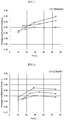
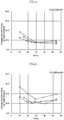
- Figures 1, 2 , and 3 disclosed in EXAMPLE 1 show relations between an average COF and an Fe/Cu value in braking test condition at 160, 325, and 360km/h respectively.
- the symbols " ⁇ ", “ ⁇ ” and “ ⁇ ” show the data of materials sintered at 950, 1030 and 1030°C respectively.
- the chemical composition of the materials is shown in Table 1 of Examples described later.
- the average COF increased with an increase in the Fe/Cu value.
- the average COF tends to be smaller when the Fe/Cu value becomes greater.
- the average COF becomes significantly smaller in a region of the Fe/Cu value.
- the gist of the present invention is described by a disk brake pad material according to claim 1, and by a use of the sintered friction material for a disk brake pad according to claim 4.
- the sintered friction material for a high-speed railway of the present invention exhibits large braking power and is excellent in stability of braking power at a high temperature. Accordingly, the sintered friction material for a high-speed railway of the present invention is suitable for brake lining for a high-speed railway in which the largest braking power is required among various transport vehicles, for example.
- Cu is an element having high thermal conductivity, and serves as a base metal of the sintered friction material in the present invention.
- the Cu content should be 50% or more.
- the upper limit of the Cu content may be defined in relation with additive components, and is not limited to specific one, but it is preferably 67% or less.
- Fe is an element exhibiting the most significant "similar-composition-metal contact effect" relative to a steel disk.
- the Fe content should be 7.5% or more.
- the Fe content has no specific upper limit, but the excessive Fe content may deteriorate the wear resistance in case of the improper sintering temperature. Hence, it is preferable to set the Fe content to be 63% or less.
- the insufficient Fe content in relation with the Cu content may provide an insufficient COF, or cause a deterioration of the wear resistance.
- the mass ratio between Fe and Cu (Fe/Cu) should be 0.15 or more.
- excessive Fe/Cu likely causes the dropout of Fe particles, which rather deteriorates the COF. Accordingly, Fe/Cu is set to be 0.40 or less. It is preferable to set Fe/Cu to be 0.36 or less.
- Fe powder having a particle diameter of 45 ⁇ m or less is used as a raw material of the sintered friction material.
- Fe powder having a too small particle diameter increases its surface area per unit volume, so that the particles are likely to become agglomerated, which deteriorates both sinterability and uniform dispersion; thus it is preferable to set the particle diameter 5 ⁇ m or more.
- Fe powder previously subjected to heat treatment in an atmosphere of hydrogen gas or ammonia gas (AX gas) is used, and the Fe powder treated in this manner hinders sinterability, as described in Patent Document 7. Accordingly, it is preferable to use mill scale powder as the Fe powder to be added as a raw material of the sintered friction material, rather than the Fe powder treated in this manner.
- any component may be employed in the metal matrix included in the sintered friction material as far as the component contains predetermined amount of Fe and Cu.
- elements other than Fe and Cu, such as Cr and Mo, may further be contained in addition to Fe and Cu so as to enhance strength.
- Graphite becomes useful for suppressing adhesion between a disk and a lining, and enhancing stabilization of the COF and the wear resistance if graphite is disposed between the disk and the lining.
- the graphite content should exceed 5% to attain this effect.
- the content thereof of more than 15% deteriorates material strength of the sintered body.
- Molybdenum disulfide 0.3 to 7%
- Molybdenum disulfide (MoS 2 ) is useful for stabilization of COF and enhancement of the wear resistance, as similar to graphite, and has effect of preventing a so-called "brake noise", and also has effect of providing lubricity in case of high load. These effects cannot be exerted if the MoS 2 content is less than 0.3%.
- the MoS 2 content of more than 7% significantly deteriorates the material strength of the sintered body, and hinders the wear resistance.
- Silica (SiO 2 ) is effective to remove an oxide film generated on a surface of the disk of the counter member by a so-called “scratching effect", and stably generate adhesion of Fe between the disk and the lining, thereby secure the friction force.
- the SiO 2 content of less than 0.5% attains no scratching effect, and the content thereof of more than 10% rather damages and roughens a surface of the disk.
- the sintered friction material may include the above various components. Various components other than the aforementioned components that are usually added to the sintered friction material may also be contained. For example, a lubricant component such as tungsten disulfide, bismuth, and antimony, and a compound such as alumina, mullite, silicon nitride, and zircon sand may be contained.
- the sintered friction material of the present invention preferably has density of 4.6 or more so as to attain sufficient strength.
- the sintered friction material of the present invention may be produced by a general producing method, for example, by mixing Fe powder and various additives with Cu powder, and compacting and sintering them. Instead of mixing Cu and Fe powders, Fe-Cu alloy powder produced by atomizing or the like may be used.
- Adding Fe powder to Cu powder allows the Fe phase having a risk of increase in temperature during braking to be involved in the Cu phase exhibiting high thermal conductivity, so that it is possible to enhance stability of braking at a high temperature, and to reinforce the Cu phase at the same time, thereby enhancing the wear resistance.
- a surface thereof becomes melted due to friction heat during braking.
- the wear characteristics of the sintered body is influenced by a neck strength of the sintered body, and if a difference in thermal expansion among the bound particles is large, the sintered body may be ruptured because of distortion caused by inhomogeneous thermal expansion.
- Fe particles and Cu particles that have large difference in thermal expansion are used.
- the sintering temperature as close as possible to the melting point of Cu, and it is preferable to set this temperature at higher than 1000°C.
- This configuration allows the structure of the sintered body to withstand distortion caused by the thermal expansion during braking, thereby enhancing the wear resistance. Meanwhile, sintering at an excessively high temperature attains no effect commensurate with the cost. Accordingly, it is preferable to set the upper limit of the sintering temperature at 1083°C which does not exceed the melting point of Cu.
- the produced sintered body is cut out in a predetermined size by common electrical discharge machining, and is mounted to a brake system so as to be used as brake lining.
- test specimens shown in Figure 2 of "5.1 Shape and Dimension of Test Specimen” of "5. Test Specimen”, and the strength was measured using a jig for the rotary three-point bending test shown in Figure 1a of "4.2 Test Jig” of "4. Apparatus and Implement”.
- Micro Vickers hardness (load of 50g, MHv of 50) was measured for the hardness. No measurement for the hardness was conducted on No. 2, and 4 specimens.
- a bench test equipment with a brake disk (outer diameter of 400 mm, thickness of 20 mm, made of forged steel) which is half the size of an actual body (Shinkansen) was used. The test was conducted on each sintered friction material three times at initial speeds of 160, 325, and 365 km/h.
- the amount of wear (g / each surface) for each sintered friction material was measured based on the difference in weight of the lining material before and after the test, and each average value of the above three trials of the test is also shown in Table 3.
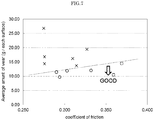
- the relation between the average amount of wear and the average COF in the test at 365 km/h was evaluated. The result thereof is shown in table 3.
- the relation between the above results and the Fe/Cu value is shown in Figs. 1 to 7 .
- the target value for the average COF in the test at the initial speed of 365 km/h is 0.28 or more.
- the target for the average amount of wear in the same test is required to satisfy the relation: M ⁇ 38.2 ⁇ F + 0.345 (where "M” denotes the average amount of wear, and "F” denotes the average COF).
- M denotes the average amount of wear
- F denotes the average COF
- the above target value for the average amount of wear was defined based on the following: that if the average amount of wear is small, the pressing force (loading force) can be increased even with a small average COF, thereby securing sufficient braking power; and if the average COF is high although the amount of wear is large, sufficient braking power can be secured even with a small pressing force (loading force).
- the sintered friction material of the present invention exhibits high braking power, and is excellent in stability of braking power at a high temperature. Accordingly, the sintered friction material of the present invention is suitable for a break lining of a high-speed railway in which the highest braking power is required among various transport vehicles, for example.
Landscapes
- Chemical & Material Sciences (AREA)
- Engineering & Computer Science (AREA)
- Mechanical Engineering (AREA)
- General Engineering & Computer Science (AREA)
- Materials Engineering (AREA)
- Metallurgy (AREA)
- Organic Chemistry (AREA)
- Inorganic Chemistry (AREA)
- Braking Arrangements (AREA)
- Powder Metallurgy (AREA)
Description
- The present invention relates to a sintered friction material useful as a brake lining material and a disk brake pad material for use in a high-speed railway vehicle.
- Traveling at a speed higher than 300 km/h has been common in high-speed railways of the world, such as German ICE and French TGV. In Japan, each company of the Japan Railways Group has made great efforts to enhance a traveling speed of the Shinkansen. In order to enhance the traveling speed, brakes that can reliably stop even trains travelling at a high-speed are indispensable. Particularly in Japan where there are high risks of natural disasters such as earthquakes, it is essential to enhance performance and reliability of brakes to reliably stop trains in a short distance even when the regenerative brake system is out of function.
- Various sintered materials are disclosed as materials for use in brake lining materials, disk brake pad materials, and others (see Patent Documents 1 to 8). Most of the conventional lining materials including metallic sintered materials are produced by adding hard particles (ceramics such as silica) to exert mechanical action (scratching action) and secure a sufficient coefficient of friction (referred as COF, µ), but some of conventional lining materials are produced by adding elements such as Fe in lining materials so as to enhance the coefficient of friction.
- For example, Patent Document 7 discloses an invention directed to "a copper-based sintered friction material consisting of 55 to 80 wt% matrix metal and 20 to 45 wt% a filler component, such as lubricant and a friction adjusting material. The matrix metal comprises 0.5 to 15 wt% tin power, 0.1 to 30 wt% zinc powder, 5 to 25 wt% nickel power, 5 to 25 wt% iron powder, 0.1 to 20 wt% stainless steel powder, the balance comprising copper powder. Wherein
- (1) total amount of the iron powder and the stainless steel powder is 8 to 28 wt%, and
- (2) the iron powder is electrolytic iron powder whose particle diameter is within a range of 40 to 150 µm, and is subjected to heat treatment at 600 to 1200°C in a hydrogen gas or an ammonia gas (AX gas) atmosphere."
- The invention disclosed in Patent Document 7 describes that if electrolytic iron powder and stainless steel powder are used in combination, the iron component works as a component that hinders sinterability, thereby causes cavities in the vicinity of the iron component of the matrix phase. The cavities react similarly with pores in a friction material, or a grinding material, and contribute to a stable friction during a hard-braking.
- Patent Document 8 describes an invention directed to "a sintered friction-material consisting metallic matrix, a grinding material, and lubricant. The matrix comprises 25 to 50 vol% cast iron, and 1 to 7 vol% copper." In the invention of Patent Document 8, an Fe-based sintered material is used instead of a conventional Cu-based sintered material, thereby enhances a frictional property during braking at a high temperature.
-
- Patent Document 1:
JP60-106932A - Patent Document 2:
JP63-109131A - Patent Document 3:
JP2-10857A - Patent Document 4:
JP3-68091A - Patent Document 5:
JP6-45837A - Patent Document 6:
JP7-65132A - Patent Document 7:
JP2006-16680A - Patent Document 8:
JP2007-126738A -
US 3 191 278 A discloses a friction material composition comprising -in weight%- 50% to 80% copper; 5% to 15% graphite; up to 20% iron, preferably 9.5%; up to 6% molybdenum disulfide, preferably 4%; and up to 5% silica, preferably 3.5%. -
US 2 408 430 A discloses a friction material composition comprising: -in weight%- 60% to 75% copper; 3-10% graphite; 4-10% iron; 3-12% molybdenum disulfide; and 2-7% silica. -
US 2009/008210 A1 discloses a friction material composition for "modern drive trains" comprising -in weight%- 50.0% copper, 10.0% iron, 9.0% graphite, 4.5% molybdenum disulphide, and 1.5% silicon oxide. - Any composition and structure of a lining material were not designed based on the grasp of a sliding mechanism between a brake disk and a lining in none of the prior arts, in which designing has been done empirically. A mechanism of exerting braking power by a scratching action of hard particles doesn't seem to be applicable to the friction material design for high-speed railways running 350 km/h or higher, which generates a safety problem. In addition, it is supposed that larger braking power attained by the scratching action of hard particles requires a greater amount of hard particles, and results in a significant increase in production cost.
- In the invention of Patent Document 7, as shown in Table 1 in Example, the Cu content doesn't exceed 41 mass% in the entire sintered material, and consequently sufficient thermal conductivity cannot be secured. In the invention of Patent Document 8, an Fe-based sintered material containing Fe more than Cu is used, and this material is similar to a material of a counter member, such as a brake disk; therefore the amount of wear by braking becomes extremely great.
- An object of the present invention is to provide a sintered friction material for a high-speed railway having a high COF, and excellent wear resistance against a steel material of a counter member (e.g. brake disk).
- The present inventors have studied particularly on a sintered friction material included in lining used for a disk made of forged steel or cast steel. The present inventors have confirmed that in case a lining comprises Fe powder, the lining and the opposite disk adhere to each other through the reaction of Fe in both friction materials. That yields high COF. Such an effect that increases adhesion between the similar composition metals, or between eutectic metals during braking is well-known as the "similar-composition metal contact effect" in the tribology field, and is considered unfavorable for mechanical products because of seizure. On the other hand, it was found that Fe addition in a metal material increases COF. Such heavy friction raises the temperature during braking and deteriorates the wear resistance.
- The present inventors have conducted various studies to solve the above conventional problems, and consequently have found that the addition of appropriate amount of Fe in a friction material increases COF properly and the adoption of Cu to the basic metallic phase prevents excessive increase in temperature caused by the Fe addition because of high thermal conductivity. That results in the enhancement of stability of braking power at a higher temperature.
-
Figures 1, 2 , and3 disclosed in EXAMPLE 1 show relations between an average COF and an Fe/Cu value in braking test condition at 160, 325, and 360km/h respectively. In the figures, the symbols "○", "◇" and "□" show the data of materials sintered at 950, 1030 and 1030°C respectively. The chemical composition of the materials is shown in Table 1 of Examples described later. - As shown in
Fig. 1 , in case of the test at 160km/h, the average COF increased with an increase in the Fe/Cu value. As shown inFig. 2 , however, in case of the test at 325km/h, the average COF tends to be smaller when the Fe/Cu value becomes greater. As shown inFig. 3 , in case of the test at 365k/h, the average COF becomes significantly smaller in a region of the Fe/Cu value. As shown in the figures, it is understood that with an increase in Fe/Cu value the average COF increased at 160 km/h. But that with an increase in Fe/Cu value the average COF decreased at 350 km/h that is the expected maximum velocity of the futuristic high-speed railways. Consequently a too large Fe/Cu value rather deteriorates the average COF and results in the smaller braking power. - Based on the above findings the present invention has been done. The gist of the present invention is described by a disk brake pad material according to claim 1, and by a use of the sintered friction material for a disk brake pad according to claim 4.
- The sintered friction material for a high-speed railway of the present invention exhibits large braking power and is excellent in stability of braking power at a high temperature. Accordingly, the sintered friction material for a high-speed railway of the present invention is suitable for brake lining for a high-speed railway in which the largest braking power is required among various transport vehicles, for example.
-
-
Figure 1 shows a relation between an average coefficient of friction and an Fe/Cu value in a test at 160 km/h. -
Figure 2 shows a relation between the average coefficient of friction and the Fe/Cu value in a test at 325 km/h. -
Figure 3 shows a relation between the average coefficient of friction and the Fe/Cu value in a test at 365 km/h. -
Figure 4 show a relation between an average amount of wear and an Fe/Cu value in a test at 160 km/h. -
Figure 5 shows a relation between the average amount of wear and the Fe/Cu value in a test at 325 km/h. -
Figure 6 shows a relation between the average amount of wear and the Fe/Cu value in a test at 365 km/h. -
Figure 7 shows a relation between the average amount of wear and the average coefficient of friction in a test at 365 km/h. - Hereinafter, a description will be provided on the embodiment of the present invention by using an example in which the sintered friction material of the present invention is applied to the brake lining. Every component contained in the sintered friction material relates to each other, and influences each other in its friction property; therefore, it is not always appropriate to individually discuss a reason for limiting each component, but a general reason for such limitation will be provided as follow. The percent sign "%" for each component denotes "mass %" in the following description.
- Cu is an element having high thermal conductivity, and serves as a base metal of the sintered friction material in the present invention. In order to obtain a Cu-based sintered body, the Cu content should be 50% or more. The upper limit of the Cu content may be defined in relation with additive components, and is not limited to specific one, but it is preferably 67% or less.
- Fe is an element exhibiting the most significant "similar-composition-metal contact effect" relative to a steel disk. In order to exert this effect, the Fe content should be 7.5% or more. The Fe content has no specific upper limit, but the excessive Fe content may deteriorate the wear resistance in case of the improper sintering temperature. Hence, it is preferable to set the Fe content to be 63% or less.
- The insufficient Fe content in relation with the Cu content may provide an insufficient COF, or cause a deterioration of the wear resistance. Hence, the mass ratio between Fe and Cu (Fe/Cu) should be 0.15 or more. On the other hand, excessive Fe/Cu likely causes the dropout of Fe particles, which rather deteriorates the COF. Accordingly, Fe/Cu is set to be 0.40 or less. It is preferable to set Fe/Cu to be 0.36 or less.
- In order to attain preferable sinterability, or to uniformly disperse Fe that dominates the friction force, Fe powder having a particle diameter of 45 µm or less is used as a raw material of the sintered friction material. Fe powder having a too small particle diameter increases its surface area per unit volume, so that the particles are likely to become agglomerated, which deteriorates both sinterability and uniform dispersion; thus it is preferable to set the particle diameter 5 µm or more.
- In the invention described in Patent Document 7, Fe powder previously subjected to heat treatment in an atmosphere of hydrogen gas or ammonia gas (AX gas) is used, and the Fe powder treated in this manner hinders sinterability, as described in Patent Document 7. Accordingly, it is preferable to use mill scale powder as the Fe powder to be added as a raw material of the sintered friction material, rather than the Fe powder treated in this manner.
- Any component may be employed in the metal matrix included in the sintered friction material as far as the component contains predetermined amount of Fe and Cu. For example, elements other than Fe and Cu, such as Cr and Mo, may further be contained in addition to Fe and Cu so as to enhance strength.
- Graphite becomes useful for suppressing adhesion between a disk and a lining, and enhancing stabilization of the COF and the wear resistance if graphite is disposed between the disk and the lining. The graphite content should exceed 5% to attain this effect. On the other hand, the content thereof of more than 15% deteriorates material strength of the sintered body.
- Molybdenum disulfide (MoS2) is useful for stabilization of COF and enhancement of the wear resistance, as similar to graphite, and has effect of preventing a so-called "brake noise", and also has effect of providing lubricity in case of high load. These effects cannot be exerted if the MoS2 content is less than 0.3%. The MoS2 content of more than 7% significantly deteriorates the material strength of the sintered body, and hinders the wear resistance.
- Silica (SiO2) is effective to remove an oxide film generated on a surface of the disk of the counter member by a so-called "scratching effect", and stably generate adhesion of Fe between the disk and the lining, thereby secure the friction force. The SiO2 content of less than 0.5% attains no scratching effect, and the content thereof of more than 10% rather damages and roughens a surface of the disk.
- The sintered friction material may include the above various components. Various components other than the aforementioned components that are usually added to the sintered friction material may also be contained. For example, a lubricant component such as tungsten disulfide, bismuth, and antimony, and a compound such as alumina, mullite, silicon nitride, and zircon sand may be contained. The sintered friction material of the present invention preferably has density of 4.6 or more so as to attain sufficient strength.
- The sintered friction material of the present invention may be produced by a general producing method, for example, by mixing Fe powder and various additives with Cu powder, and compacting and sintering them. Instead of mixing Cu and Fe powders, Fe-Cu alloy powder produced by atomizing or the like may be used.
- Adding Fe powder to Cu powder allows the Fe phase having a risk of increase in temperature during braking to be involved in the Cu phase exhibiting high thermal conductivity, so that it is possible to enhance stability of braking at a high temperature, and to reinforce the Cu phase at the same time, thereby enhancing the wear resistance.
- In a lining for a high speed railway, a surface thereof becomes melted due to friction heat during braking. This means that the lining is heated approximately up to a melting point of Cu having the lowest melting point (1083°C) in the particles constituting the lining during braking. The wear characteristics of the sintered body is influenced by a neck strength of the sintered body, and if a difference in thermal expansion among the bound particles is large, the sintered body may be ruptured because of distortion caused by inhomogeneous thermal expansion. In the present invention, Fe particles and Cu particles that have large difference in thermal expansion (the coefficient of thermal expansion at a room temperature is 11.7 × 10⁻⁶ /°C for Fe, and 16.5 × 10⁻⁶ /°C for Cu) are used. Hence, it is effective to set the sintering temperature as close as possible to the melting point of Cu, and it is preferable to set this temperature at higher than 1000°C. This configuration allows the structure of the sintered body to withstand distortion caused by the thermal expansion during braking, thereby enhancing the wear resistance. Meanwhile, sintering at an excessively high temperature attains no effect commensurate with the cost. Accordingly, it is preferable to set the upper limit of the sintering temperature at 1083°C which does not exceed the melting point of Cu.
- The produced sintered body is cut out in a predetermined size by common electrical discharge machining, and is mounted to a brake system so as to be used as brake lining.
- After mixing the raw material powders shown in Table 1, the materials were sintered by the process shown in Table 1. The strength, hardness, and density of each produced sintered friction material were measured with the following method. The result thereof is also described in Table 2. Of the raw material powder, CE-15 of Fukuda Metal Foil & Powder Co., LTD (electrolytic copper powder, maximum particle diameter of 75 µm) was used as Cu, ASC300 of Höganäs AB (mill scale powder, restored, maximum particle diameter of 45 µm) was used as Fe, CRE03PB of Japan Pure Chemical Co., Ltd. (maximum particle diameter of 63 µm) was used as Cr, MOE02PB of Japan Pure Chemical Co., Ltd. (maximum particle diameter of 63 µm) was used as Mo, SGP-100 of SEC Carbon Ltd. (flat artificial graphite, average particle diameter of 120 µm) was used as graphite, 010-51125 of Kishida Chemical Co., Ltd. was used as MoS2, and SIO08PB of Japan Pure Chemical Co., Ltd. (average particle diameter of 4 µm) was used as SiO2, respectively.
- In compliant with JIS R1601:2008, there were prepared test specimens shown in
Figure 2 of "5.1 Shape and Dimension of Test Specimen" of "5. Test Specimen", and the strength was measured using a jig for the rotary three-point bending test shown inFigure 1a of "4.2 Test Jig" of "4. Apparatus and Implement". - Micro Vickers hardness (load of 50g, MHv of 50) was measured for the hardness. No measurement for the hardness was conducted on No. 2, and 4 specimens.
- Measurement for the density was conducted with the Archimedes method.
- Each measurement result is shown in Table 2
-
Table 1 No. Chemical composition (mass%) Fe/Cu Sintering temperature (°C) remarks Cu Fe Cr Mo graphite MoS2 SiO2 1 50.0 27.0 7.5 1.0 12.5 1.5 0.5 0.540 950 Comparative Example 2 55.0 22.0 7.5 1.0 12.5 1.5 0.5 0.400 950 Comparative Examples 3 60.0 17.0 7.5 1.0 12.5 1.5 0.5 0.280 950 4 65.0 12.0 7.5 1.0 12.5 1.5 0.5 0.185 950 5 70.0 7.0 7.5 1.0 12.5 1.5 0.5 0.100 950 Comparative Example 6 50.0 27.0 7.5 1.0 12.5 1.5 0.5 0.540 1,000 Comparative Example 7 57.0 20.0 7.5 1.0 12.5 1.5 0.5 0.351 1,000 Comparative Examples 8 62.0 15.0 7.5 1.0 12.5 1.5 0.5 0.242 1,000 9 67.0 10.0 7.5 1.0 12.5 1.5 0.5 0.149 1,000 Comparative Example 10 50.0 27.0 7.5 1.0 12.5 1.5 0.5 0.540 1,030 Comparative Example 11 60.0 17.0 7.5 1.0 12.5 1.5 0.5 0.283 1,030 Example of the present invention 12 70.0 7.0 7.5 1.0 12.5 1.5 0.5 0.100 1,030 Comparative Example *means it does not meet the claimed range. -
Table 2 No. Bending Strength (MPa) Hardness (MHv50) Density (g/cm3) remarks 1 59.6 89.2 4.9 Comparative Example 2 68.3 - 4.9 Comparative Examples 3 66.6 87.8 4.8 4 65.4 - 4.9 5 74.0 87.6 4.9 Comparative Example 6 55.3 87.5 4.9 Comparative Example 7 62.4 85.5 4.9 Comparative Examples 8 67.5 86.9 5.0 9 77.0 85.6 5.1 Comparative Example 10 37.1 86.3 4.9 Comparative Example 11 47.9 85.6 5.0 Example of the present invention 12 55.7 85.2 5.1 Comparative Example - The coefficient of friction and the amount of wear were measured on each sintered friction material in accordance with the following method.
- A bench test equipment with a brake disk (outer diameter of 400 mm, thickness of 20 mm, made of forged steel) which is half the size of an actual body (Shinkansen) was used. The test was conducted on each sintered friction material three times at initial speeds of 160, 325, and 365 km/h. Four pieces of the lining material (38 mm × 55 mm × 15 mm) cut out from each sintered friction material were rigidly fixed (nonisobaric structure) onto a surface of each caliper, that is, eight pieces of the lining material were fixed onto both surfaces of the calipers in total, and these pieces of the lining material were pushed with a load of 2.24kN (constant) against both surfaces of the disk at positions of 170 mm radially extending from a center of the disk, and in this state, torque was measured to calculate the COF (µ) for each sintered friction material; and each average value of the above three trials of the test is shown in Table 3. The amount of wear (g / each surface) for each sintered friction material was measured based on the difference in weight of the lining material before and after the test, and each average value of the above three trials of the test is also shown in Table 3. The relation between the average amount of wear and the average COF in the test at 365 km/h was evaluated. The result thereof is shown in table 3. The relation between the above results and the Fe/Cu value is shown in
Figs. 1 to 7 . - The target value for the average COF in the test at the initial speed of 365 km/h is 0.28 or more. In relation with the average COF, the target for the average amount of wear in the same test is required to satisfy the relation: M ≤ 38.2 × F + 0.345 (where "M" denotes the average amount of wear, and "F" denotes the average COF). A case of satisfying this relation is denoted by a symbol "○", and a case of unsatisfying this relation is denoted by a symbol "×". The above target value for the average amount of wear was defined based on the following: that if the average amount of wear is small, the pressing force (loading force) can be increased even with a small average COF, thereby securing sufficient braking power; and if the average COF is high although the amount of wear is large, sufficient braking power can be secured even with a small pressing force (loading force).
-
Table 3 No. Average coefficient of friction µ Average amount of wear (g / each surface) evaluation remarks 160km/h 325km/h 365km/h 160km/h 325km/h 365km/h 1 0.351 0.289 0.276 0.78 8.00 14.30 × Comparative Example 2 0.349 0.298 0.294 0.85 7.38 9.72 ○ Comparative Examples 3 0.351 0.301 0.303 1.40 7.50 11.92 ○ 4 0.334 0.278 0.290 1.50 9.10 11.43 ○ 5 0.307 0.266 0.276 1.65 12.42 16.77 × Comparative Example 6 0.411 0.320 0.315 0.79 6.22 13.65 × Comparative Example 7 0.382 0.335 0.332 0.80 7.20 12.00 ○ Comparative Examples 8 0.368 0.323 0.359 1.50 8.30 10.50 ○ 9 0.364 0.271 0.310 0.70 13.50 16.20 × Comparative Example 10 0.447 0.360 0.327 0.95 9.48 19.37 × Comparative Example 11 0.392 0.371 0.369 1.53 8.05 14.45 ○ Example of the present invention 12 0.317 0.287 0.275 1.65 18.45 26.75 × Comparative Example - As shown in Table 3, and
Figs. 1 to 7 , in Inventive Example of the present invention (No. 11), a high average COF can be attained even at 365 km/h in each case, and sufficiently small average amount of wear can also be attained in relation with the average COF; thus such performance could be attained. That is preferable enough for use as the sintered friction material for a high-speed railway. On the contrary, Comparative Example (No. 1, 5, 6, 9, 10, and 12) could not be used as the sintered friction material for a high-speed railway because the average COFs were too small (No. 1, 5, and 12), or the average amounts of wear were too large (No. 6, 9, and 10). - The sintered friction material of the present invention exhibits high braking power, and is excellent in stability of braking power at a high temperature. Accordingly, the sintered friction material of the present invention is suitable for a break lining of a high-speed railway in which the highest braking power is required among various transport vehicles, for example.
Claims (4)
- A disk brake pad material made of a sintered friction material for a high-speed railway containing, by mass%, Fe of 7.5% or more, Cu of 50% or more, graphite of 5 to 15%, molybdenum disulfide of 0.3 to 7%, and silica of 0.5 to 10%, wherein Fe/Cu is 0.15 to 0.40,wherein a relation between an average amount of wear M and an average coefficient of friction F of the sintered friction material satisfies a formula: M ≤ 38.2 × F+ 0.345 which is obtained by the wearing test having steps:preparing four pairs of lining pieces each having a length of 55 mm, a width of 38 mm, and a thickness of 15 mm;placing the four pairs of lining pieces on a brake disk made of forged steel having an outer diameter of 400 mm, and a thickness of 20 mm, where the four pairs of the lining pieces are placed at positions of 170 mm radially extending from a center of the brake disk with constant intervals in a rotational axial direction of the brake disk; andimpressing the four pairs of the lining pieces onto both surfaces of the brake disk with a load of 2.24 kN so as to brake a wheel rotating at an initial speed of 365 km/h,wherein the sintered friction material is sintered at a temperature of higher than 1000°C, andwherein Fe powder having a particle diameter of 45 µm or less is used as a raw material of the sintered friction material.
- The disk brake pad material for a high-speed railway according to claim 1, wherein mill scale powder is used as Fe powder.
- The disk brake pad material for a high-speed railway according to claim 1 or 2, wherein the sintered friction material has a density of 4.6 or more.
- Use of the sintered friction material for a disk brake pad according to any one of the preceding claims for a high-speed railway traveling at a speed higher than 300 km/h.
Applications Claiming Priority (2)
| Application Number | Priority Date | Filing Date | Title |
|---|---|---|---|
| JP2011075343A JP5716494B2 (en) | 2011-03-30 | 2011-03-30 | Sintered friction material for high-speed railway |
| PCT/JP2012/058102 WO2012133513A1 (en) | 2011-03-30 | 2012-03-28 | Sintered friction material for high-speed rail |
Publications (4)
| Publication Number | Publication Date |
|---|---|
| EP2692876A1 EP2692876A1 (en) | 2014-02-05 |
| EP2692876A4 EP2692876A4 (en) | 2014-10-15 |
| EP2692876B1 EP2692876B1 (en) | 2019-03-20 |
| EP2692876B2 true EP2692876B2 (en) | 2022-01-05 |
Family
ID=46931222
Family Applications (1)
| Application Number | Title | Priority Date | Filing Date |
|---|---|---|---|
| EP12762964.0A Active EP2692876B2 (en) | 2011-03-30 | 2012-03-28 | Sintered friction material for high-speed rail |
Country Status (9)
| Country | Link |
|---|---|
| US (1) | US20140109723A1 (en) |
| EP (1) | EP2692876B2 (en) |
| JP (1) | JP5716494B2 (en) |
| KR (2) | KR101892772B1 (en) |
| CN (1) | CN103459626A (en) |
| BR (1) | BR112013025270A2 (en) |
| ES (1) | ES2722228T5 (en) |
| TW (1) | TWI476285B (en) |
| WO (1) | WO2012133513A1 (en) |
Families Citing this family (15)
| Publication number | Priority date | Publication date | Assignee | Title |
|---|---|---|---|---|
| WO2014157089A1 (en) * | 2013-03-25 | 2014-10-02 | 新日鐵住金株式会社 | Copper alloy powder, sintered copper alloy body and brake lining for use in high-speed railway |
| EP3028983B1 (en) * | 2014-12-05 | 2018-02-07 | Zollern GmbH & Co. KG | Winch, in particular free fall winch with a service and holding brake |
| JP6329088B2 (en) * | 2015-01-30 | 2018-05-23 | 株式会社シマノ | Brake pad for bicycle and method for manufacturing the same |
| WO2017059026A1 (en) * | 2015-09-29 | 2017-04-06 | Höganäs Ab (Publ) | New iron-based composite powder |
| RU2627138C1 (en) * | 2016-06-27 | 2017-08-03 | Государственное научное учреждение "Институт порошковой металлургии" | Copper-based sintered friction material |
| CN107245676B (en) * | 2016-11-21 | 2019-04-16 | 西安航空制动科技有限公司 | Copper-based powder metallurgy friction material for high-speed linear brake and preparation method thereof |
| EP3550042B1 (en) | 2016-12-01 | 2022-02-16 | Fine Sinter Co., Ltd. | Sintered friction material for railway vehicles, method for producing the same and use thereof |
| CN107606007B (en) * | 2017-10-17 | 2019-11-05 | 湖北飞龙摩擦密封材料股份有限公司 | A kind of high-speed rail brake lining and its manufacturing method |
| CN109185369A (en) * | 2018-10-16 | 2019-01-11 | 北京天仁道和新材料有限公司 | A kind of powder metallurgy brake flat and preparation method thereof |
| AT522255B1 (en) | 2019-03-13 | 2022-01-15 | Miba Frictec Gmbh | friction lining |
| IT201900016835A1 (en) * | 2019-09-20 | 2021-03-20 | Cofren Srl | PAIR OF DISC / BRAKE FRICTION FOR RAILWAY VEHICLES |
| KR102454674B1 (en) | 2020-12-03 | 2022-10-18 | 한국철도기술연구원 | Friction characteristic analysis method according to the component ratio of the friction pad for railway vehicles |
| CN112570709A (en) * | 2020-12-29 | 2021-03-30 | 沈阳远程摩擦密封材料有限公司 | Powder sintered brake pad for braking high-speed railway at speed of 420km/h |
| DE102021207257A1 (en) | 2021-07-08 | 2023-01-12 | Volkswagen Aktiengesellschaft | Method for determining a coefficient of friction between a sintering base and a component, computer program product and sintering device |
| CN115466876B (en) * | 2022-10-12 | 2023-08-22 | 湖南博云新材料股份有限公司 | Powder metallurgy friction material for unmanned aerial vehicle brake pair and preparation process thereof |
Citations (2)
| Publication number | Priority date | Publication date | Assignee | Title |
|---|---|---|---|---|
| FR1502916A (en) † | 1965-10-15 | 1967-11-24 | Bendix Corp | Copper-based friction substance and frèis linings made from this substance |
| US4855336A (en) † | 1988-07-25 | 1989-08-08 | Allied-Signal Inc. | Friction material containing mill scale |
Family Cites Families (17)
| Publication number | Priority date | Publication date | Assignee | Title |
|---|---|---|---|---|
| US2408430A (en) * | 1944-04-04 | 1946-10-01 | Sk Wellman Co | Friction composition product |
| US2886882A (en) * | 1956-06-06 | 1959-05-19 | S K Wellman Co | Friction composition product |
| US2945291A (en) * | 1958-11-28 | 1960-07-19 | Gen Motors Corp | Frictional material |
| US3191278A (en) * | 1963-10-21 | 1965-06-29 | American Brake Shoe Co | Friction composition |
| JPS60106932A (en) | 1983-11-14 | 1985-06-12 | Nippon Funmatsu Gokin Kk | Sintered friction material |
| JPH0765132B2 (en) | 1986-10-24 | 1995-07-12 | 日本粉末合金株式会社 | Sintered alloy friction material |
| JPH0210857A (en) | 1988-06-29 | 1990-01-16 | Toshiba Corp | Semiconductor device |
| JPH0368091A (en) | 1989-08-08 | 1991-03-25 | Seiko Epson Corp | character recognition device |
| JPH0645837A (en) | 1992-07-22 | 1994-02-18 | Nec Kansai Ltd | Protecting circuit |
| JP3339122B2 (en) | 1993-08-24 | 2002-10-28 | 松下電器産業株式会社 | Driver's license recognition device |
| TW267213B (en) * | 1994-12-29 | 1996-01-01 | Da Jie Entpr Co Ltd | Process of producing semi-metallic brake pad |
| JP4197751B2 (en) * | 1997-02-17 | 2008-12-17 | 東海カーボン株式会社 | Metallic friction material and method for manufacturing the same |
| JPH10287941A (en) * | 1997-04-16 | 1998-10-27 | Toyota Motor Corp | Sintered friction member and method of manufacturing the same |
| JP2000328171A (en) * | 1999-05-25 | 2000-11-28 | Akechi Ceramics Co Ltd | Inorganic friction material |
| JP4430468B2 (en) * | 2004-07-05 | 2010-03-10 | 東海カーボン株式会社 | Copper-based sintered friction material |
| JP2007126738A (en) | 2005-11-07 | 2007-05-24 | Akebono Brake Ind Co Ltd | Sintered frictional material |
| AT505425B1 (en) * | 2007-07-04 | 2017-09-15 | Miba Frictec Gmbh | TROCKENLAUFREIBBELAG |
-
2011
- 2011-03-30 JP JP2011075343A patent/JP5716494B2/en not_active Expired - Fee Related
-
2012
- 2012-03-28 KR KR1020137026837A patent/KR101892772B1/en not_active Expired - Fee Related
- 2012-03-28 CN CN2012800164138A patent/CN103459626A/en active Pending
- 2012-03-28 BR BR112013025270A patent/BR112013025270A2/en not_active Application Discontinuation
- 2012-03-28 WO PCT/JP2012/058102 patent/WO2012133513A1/en not_active Ceased
- 2012-03-28 ES ES12762964T patent/ES2722228T5/en active Active
- 2012-03-28 KR KR1020167002014A patent/KR101823797B1/en not_active Expired - Fee Related
- 2012-03-28 US US14/008,675 patent/US20140109723A1/en not_active Abandoned
- 2012-03-28 EP EP12762964.0A patent/EP2692876B2/en active Active
- 2012-03-30 TW TW101111418A patent/TWI476285B/en not_active IP Right Cessation
Patent Citations (2)
| Publication number | Priority date | Publication date | Assignee | Title |
|---|---|---|---|---|
| FR1502916A (en) † | 1965-10-15 | 1967-11-24 | Bendix Corp | Copper-based friction substance and frèis linings made from this substance |
| US4855336A (en) † | 1988-07-25 | 1989-08-08 | Allied-Signal Inc. | Friction material containing mill scale |
Non-Patent Citations (3)
| Title |
|---|
| ANONYMOUS: "High-speed rail history", UIC - INTERNATIONAL UNION OF RAILWAYS, 24 July 2015 (2015-07-24), pages 1 - 5, Retrieved from the Internet <URL:https://uic.org/passenger/highspeed/High-Speed-History> † |
| EUDIER MICHEL: "La physique du frittage", BULLETIN DE LA SOCIETE FRANGAISE DE MINERALOGIE ET DE CRISTALLOGRAPHIE, vol. 77, no. 4-6, 1954, pages 1126 - 1142 † |
| LANDOLT-BÖRNSTEIN: "9. Rail and other guided transport technologies, Sone S", GROUP VIII ADVANCED MATERIALS AND TECHNOLOGIES, 2002, DOI: 10.1007/10696439_46 † |
Also Published As
| Publication number | Publication date |
|---|---|
| US20140109723A1 (en) | 2014-04-24 |
| EP2692876A1 (en) | 2014-02-05 |
| TW201311911A (en) | 2013-03-16 |
| CN103459626A (en) | 2013-12-18 |
| KR20130143715A (en) | 2013-12-31 |
| ES2722228T5 (en) | 2022-04-08 |
| JP5716494B2 (en) | 2015-05-13 |
| JP2012207289A (en) | 2012-10-25 |
| EP2692876B1 (en) | 2019-03-20 |
| KR101823797B1 (en) | 2018-01-30 |
| WO2012133513A1 (en) | 2012-10-04 |
| BR112013025270A2 (en) | 2016-12-13 |
| ES2722228T3 (en) | 2019-08-08 |
| KR101892772B1 (en) | 2018-08-28 |
| TWI476285B (en) | 2015-03-11 |
| KR20160017106A (en) | 2016-02-15 |
| EP2692876A4 (en) | 2014-10-15 |
Similar Documents
| Publication | Publication Date | Title |
|---|---|---|
| EP2692876B2 (en) | Sintered friction material for high-speed rail | |
| JP6503229B2 (en) | Method of manufacturing sintered friction material for high speed railway vehicle | |
| CN110650812B (en) | Sintered friction material | |
| CN105506346B (en) | Powder metallurgy brake pad friction material and preparation method thereof | |
| EP3550042B1 (en) | Sintered friction material for railway vehicles, method for producing the same and use thereof | |
| CN113564406A (en) | High-melting-point alloy reinforced copper-based powder metallurgy friction material and preparation method thereof | |
| EP2979780A1 (en) | Copper alloy powder, sintered copper alloy body and brake lining for use in high-speed railway | |
| JP2019163540A (en) | Sinter friction material for high speed railway vehicle | |
| EP3875561B1 (en) | Sintered friction material and method for producing sintered friction material | |
| EP3597718A1 (en) | Sintered friction material for brake | |
| CN106838079A (en) | A kind of extremely frigid zones bullet train brake pad metallurgical friction material | |
| KR20110074003A (en) | Sintered friction material and its manufacturing method | |
| CN113102757B (en) | Metal matrix composite brake pad and preparation method thereof | |
| CN113118434B (en) | Brake pad of high-speed motor train unit and preparation method thereof | |
| CN113106360B (en) | Motor train unit brake pad and preparation method thereof | |
| TWI680188B (en) | Sintered friction material | |
| KR101453446B1 (en) | Sintered friction material having good stability and manufacturing method of the same | |
| KR101386409B1 (en) | Sintered friction material having good stability and manufacturing method of the same | |
| JPH10140274A (en) | Composite material for railway vehicle brake discs |
Legal Events
| Date | Code | Title | Description |
|---|---|---|---|
| PUAI | Public reference made under article 153(3) epc to a published international application that has entered the european phase |
Free format text: ORIGINAL CODE: 0009012 |
|
| 17P | Request for examination filed |
Effective date: 20131030 |
|
| AK | Designated contracting states |
Kind code of ref document: A1 Designated state(s): AL AT BE BG CH CY CZ DE DK EE ES FI FR GB GR HR HU IE IS IT LI LT LU LV MC MK MT NL NO PL PT RO RS SE SI SK SM TR |
|
| DAX | Request for extension of the european patent (deleted) | ||
| A4 | Supplementary search report drawn up and despatched |
Effective date: 20140912 |
|
| RIC1 | Information provided on ipc code assigned before grant |
Ipc: C22C 32/00 20060101ALI20140908BHEP Ipc: F16D 69/02 20060101ALI20140908BHEP Ipc: C22C 9/00 20060101AFI20140908BHEP |
|
| STAA | Information on the status of an ep patent application or granted ep patent |
Free format text: STATUS: EXAMINATION IS IN PROGRESS |
|
| 17Q | First examination report despatched |
Effective date: 20170216 |
|
| GRAP | Despatch of communication of intention to grant a patent |
Free format text: ORIGINAL CODE: EPIDOSNIGR1 |
|
| STAA | Information on the status of an ep patent application or granted ep patent |
Free format text: STATUS: GRANT OF PATENT IS INTENDED |
|
| INTG | Intention to grant announced |
Effective date: 20181009 |
|
| GRAS | Grant fee paid |
Free format text: ORIGINAL CODE: EPIDOSNIGR3 |
|
| GRAA | (expected) grant |
Free format text: ORIGINAL CODE: 0009210 |
|
| STAA | Information on the status of an ep patent application or granted ep patent |
Free format text: STATUS: THE PATENT HAS BEEN GRANTED |
|
| AK | Designated contracting states |
Kind code of ref document: B1 Designated state(s): AL AT BE BG CH CY CZ DE DK EE ES FI FR GB GR HR HU IE IS IT LI LT LU LV MC MK MT NL NO PL PT RO RS SE SI SK SM TR |
|
| REG | Reference to a national code |
Ref country code: GB Ref legal event code: FG4D |
|
| REG | Reference to a national code |
Ref country code: CH Ref legal event code: EP |
|
| REG | Reference to a national code |
Ref country code: DE Ref legal event code: R096 Ref document number: 602012058036 Country of ref document: DE |
|
| REG | Reference to a national code |
Ref country code: AT Ref legal event code: REF Ref document number: 1110583 Country of ref document: AT Kind code of ref document: T Effective date: 20190415 |
|
| REG | Reference to a national code |
Ref country code: IE Ref legal event code: FG4D |
|
| REG | Reference to a national code |
Ref country code: DE Ref legal event code: R082 Ref document number: 602012058036 Country of ref document: DE Representative=s name: ZIMMERMANN & PARTNER PATENTANWAELTE MBB, DE Ref country code: DE Ref legal event code: R081 Ref document number: 602012058036 Country of ref document: DE Owner name: NIPPON STEEL CORPORATION, JP Free format text: FORMER OWNER: NIPPON STEEL & SUMITOMO METAL CORPORATION, TOKYO, JP |
|
| RAP2 | Party data changed (patent owner data changed or rights of a patent transferred) |
Owner name: NIPPON STEEL CORPORATION |
|
| REG | Reference to a national code |
Ref country code: NL Ref legal event code: MP Effective date: 20190320 |
|
| PG25 | Lapsed in a contracting state [announced via postgrant information from national office to epo] |
Ref country code: SE Free format text: LAPSE BECAUSE OF FAILURE TO SUBMIT A TRANSLATION OF THE DESCRIPTION OR TO PAY THE FEE WITHIN THE PRESCRIBED TIME-LIMIT Effective date: 20190320 Ref country code: LT Free format text: LAPSE BECAUSE OF FAILURE TO SUBMIT A TRANSLATION OF THE DESCRIPTION OR TO PAY THE FEE WITHIN THE PRESCRIBED TIME-LIMIT Effective date: 20190320 Ref country code: FI Free format text: LAPSE BECAUSE OF FAILURE TO SUBMIT A TRANSLATION OF THE DESCRIPTION OR TO PAY THE FEE WITHIN THE PRESCRIBED TIME-LIMIT Effective date: 20190320 Ref country code: NO Free format text: LAPSE BECAUSE OF FAILURE TO SUBMIT A TRANSLATION OF THE DESCRIPTION OR TO PAY THE FEE WITHIN THE PRESCRIBED TIME-LIMIT Effective date: 20190620 |
|
| REG | Reference to a national code |
Ref country code: ES Ref legal event code: FG2A Ref document number: 2722228 Country of ref document: ES Kind code of ref document: T3 Effective date: 20190808 |
|
| REG | Reference to a national code |
Ref country code: LT Ref legal event code: MG4D |
|
| PG25 | Lapsed in a contracting state [announced via postgrant information from national office to epo] |
Ref country code: BG Free format text: LAPSE BECAUSE OF FAILURE TO SUBMIT A TRANSLATION OF THE DESCRIPTION OR TO PAY THE FEE WITHIN THE PRESCRIBED TIME-LIMIT Effective date: 20190620 Ref country code: RS Free format text: LAPSE BECAUSE OF FAILURE TO SUBMIT A TRANSLATION OF THE DESCRIPTION OR TO PAY THE FEE WITHIN THE PRESCRIBED TIME-LIMIT Effective date: 20190320 Ref country code: LV Free format text: LAPSE BECAUSE OF FAILURE TO SUBMIT A TRANSLATION OF THE DESCRIPTION OR TO PAY THE FEE WITHIN THE PRESCRIBED TIME-LIMIT Effective date: 20190320 Ref country code: NL Free format text: LAPSE BECAUSE OF FAILURE TO SUBMIT A TRANSLATION OF THE DESCRIPTION OR TO PAY THE FEE WITHIN THE PRESCRIBED TIME-LIMIT Effective date: 20190320 Ref country code: GR Free format text: LAPSE BECAUSE OF FAILURE TO SUBMIT A TRANSLATION OF THE DESCRIPTION OR TO PAY THE FEE WITHIN THE PRESCRIBED TIME-LIMIT Effective date: 20190621 Ref country code: HR Free format text: LAPSE BECAUSE OF FAILURE TO SUBMIT A TRANSLATION OF THE DESCRIPTION OR TO PAY THE FEE WITHIN THE PRESCRIBED TIME-LIMIT Effective date: 20190320 |
|
| REG | Reference to a national code |
Ref country code: AT Ref legal event code: MK05 Ref document number: 1110583 Country of ref document: AT Kind code of ref document: T Effective date: 20190320 |
|
| PG25 | Lapsed in a contracting state [announced via postgrant information from national office to epo] |
Ref country code: AL Free format text: LAPSE BECAUSE OF FAILURE TO SUBMIT A TRANSLATION OF THE DESCRIPTION OR TO PAY THE FEE WITHIN THE PRESCRIBED TIME-LIMIT Effective date: 20190320 Ref country code: PT Free format text: LAPSE BECAUSE OF FAILURE TO SUBMIT A TRANSLATION OF THE DESCRIPTION OR TO PAY THE FEE WITHIN THE PRESCRIBED TIME-LIMIT Effective date: 20190720 Ref country code: SK Free format text: LAPSE BECAUSE OF FAILURE TO SUBMIT A TRANSLATION OF THE DESCRIPTION OR TO PAY THE FEE WITHIN THE PRESCRIBED TIME-LIMIT Effective date: 20190320 Ref country code: EE Free format text: LAPSE BECAUSE OF FAILURE TO SUBMIT A TRANSLATION OF THE DESCRIPTION OR TO PAY THE FEE WITHIN THE PRESCRIBED TIME-LIMIT Effective date: 20190320 Ref country code: RO Free format text: LAPSE BECAUSE OF FAILURE TO SUBMIT A TRANSLATION OF THE DESCRIPTION OR TO PAY THE FEE WITHIN THE PRESCRIBED TIME-LIMIT Effective date: 20190320 Ref country code: CZ Free format text: LAPSE BECAUSE OF FAILURE TO SUBMIT A TRANSLATION OF THE DESCRIPTION OR TO PAY THE FEE WITHIN THE PRESCRIBED TIME-LIMIT Effective date: 20190320 |
|
| REG | Reference to a national code |
Ref country code: CH Ref legal event code: PL |
|
| PG25 | Lapsed in a contracting state [announced via postgrant information from national office to epo] |
Ref country code: SM Free format text: LAPSE BECAUSE OF FAILURE TO SUBMIT A TRANSLATION OF THE DESCRIPTION OR TO PAY THE FEE WITHIN THE PRESCRIBED TIME-LIMIT Effective date: 20190320 Ref country code: LU Free format text: LAPSE BECAUSE OF NON-PAYMENT OF DUE FEES Effective date: 20190328 Ref country code: PL Free format text: LAPSE BECAUSE OF FAILURE TO SUBMIT A TRANSLATION OF THE DESCRIPTION OR TO PAY THE FEE WITHIN THE PRESCRIBED TIME-LIMIT Effective date: 20190320 |
|
| REG | Reference to a national code |
Ref country code: BE Ref legal event code: MM Effective date: 20190331 |
|
| REG | Reference to a national code |
Ref country code: DE Ref legal event code: R026 Ref document number: 602012058036 Country of ref document: DE |
|
| PLBI | Opposition filed |
Free format text: ORIGINAL CODE: 0009260 |
|
| PG25 | Lapsed in a contracting state [announced via postgrant information from national office to epo] |
Ref country code: IS Free format text: LAPSE BECAUSE OF FAILURE TO SUBMIT A TRANSLATION OF THE DESCRIPTION OR TO PAY THE FEE WITHIN THE PRESCRIBED TIME-LIMIT Effective date: 20190720 Ref country code: AT Free format text: LAPSE BECAUSE OF FAILURE TO SUBMIT A TRANSLATION OF THE DESCRIPTION OR TO PAY THE FEE WITHIN THE PRESCRIBED TIME-LIMIT Effective date: 20190320 |
|
| PLAX | Notice of opposition and request to file observation + time limit sent |
Free format text: ORIGINAL CODE: EPIDOSNOBS2 |
|
| 26 | Opposition filed |
Opponent name: VRI-VERBAND DER REIBBELAGINDUSTRIE E.V. Effective date: 20191217 |
|
| PG25 | Lapsed in a contracting state [announced via postgrant information from national office to epo] |
Ref country code: DK Free format text: LAPSE BECAUSE OF FAILURE TO SUBMIT A TRANSLATION OF THE DESCRIPTION OR TO PAY THE FEE WITHIN THE PRESCRIBED TIME-LIMIT Effective date: 20190320 Ref country code: IE Free format text: LAPSE BECAUSE OF NON-PAYMENT OF DUE FEES Effective date: 20190328 Ref country code: MC Free format text: LAPSE BECAUSE OF FAILURE TO SUBMIT A TRANSLATION OF THE DESCRIPTION OR TO PAY THE FEE WITHIN THE PRESCRIBED TIME-LIMIT Effective date: 20190320 Ref country code: CH Free format text: LAPSE BECAUSE OF NON-PAYMENT OF DUE FEES Effective date: 20190331 Ref country code: LI Free format text: LAPSE BECAUSE OF NON-PAYMENT OF DUE FEES Effective date: 20190331 |
|
| PG25 | Lapsed in a contracting state [announced via postgrant information from national office to epo] |
Ref country code: BE Free format text: LAPSE BECAUSE OF NON-PAYMENT OF DUE FEES Effective date: 20190331 Ref country code: SI Free format text: LAPSE BECAUSE OF FAILURE TO SUBMIT A TRANSLATION OF THE DESCRIPTION OR TO PAY THE FEE WITHIN THE PRESCRIBED TIME-LIMIT Effective date: 20190320 |
|
| PG25 | Lapsed in a contracting state [announced via postgrant information from national office to epo] |
Ref country code: TR Free format text: LAPSE BECAUSE OF FAILURE TO SUBMIT A TRANSLATION OF THE DESCRIPTION OR TO PAY THE FEE WITHIN THE PRESCRIBED TIME-LIMIT Effective date: 20190320 |
|
| PLBB | Reply of patent proprietor to notice(s) of opposition received |
Free format text: ORIGINAL CODE: EPIDOSNOBS3 |
|
| PG25 | Lapsed in a contracting state [announced via postgrant information from national office to epo] |
Ref country code: MT Free format text: LAPSE BECAUSE OF NON-PAYMENT OF DUE FEES Effective date: 20190328 |
|
| PG25 | Lapsed in a contracting state [announced via postgrant information from national office to epo] |
Ref country code: CY Free format text: LAPSE BECAUSE OF FAILURE TO SUBMIT A TRANSLATION OF THE DESCRIPTION OR TO PAY THE FEE WITHIN THE PRESCRIBED TIME-LIMIT Effective date: 20190320 |
|
| PG25 | Lapsed in a contracting state [announced via postgrant information from national office to epo] |
Ref country code: HU Free format text: LAPSE BECAUSE OF FAILURE TO SUBMIT A TRANSLATION OF THE DESCRIPTION OR TO PAY THE FEE WITHIN THE PRESCRIBED TIME-LIMIT; INVALID AB INITIO Effective date: 20120328 |
|
| PUAH | Patent maintained in amended form |
Free format text: ORIGINAL CODE: 0009272 |
|
| STAA | Information on the status of an ep patent application or granted ep patent |
Free format text: STATUS: PATENT MAINTAINED AS AMENDED |
|
| 27A | Patent maintained in amended form |
Effective date: 20220105 |
|
| AK | Designated contracting states |
Kind code of ref document: B2 Designated state(s): AL AT BE BG CH CY CZ DE DK EE ES FI FR GB GR HR HU IE IS IT LI LT LU LV MC MK MT NL NO PL PT RO RS SE SI SK SM TR |
|
| REG | Reference to a national code |
Ref country code: DE Ref legal event code: R102 Ref document number: 602012058036 Country of ref document: DE |
|
| REG | Reference to a national code |
Ref country code: ES Ref legal event code: DC2A Ref document number: 2722228 Country of ref document: ES Kind code of ref document: T5 Effective date: 20220408 |
|
| PG25 | Lapsed in a contracting state [announced via postgrant information from national office to epo] |
Ref country code: MK Free format text: LAPSE BECAUSE OF FAILURE TO SUBMIT A TRANSLATION OF THE DESCRIPTION OR TO PAY THE FEE WITHIN THE PRESCRIBED TIME-LIMIT Effective date: 20190320 |
|
| PGFP | Annual fee paid to national office [announced via postgrant information from national office to epo] |
Ref country code: ES Payment date: 20250403 Year of fee payment: 14 |
|
| PGFP | Annual fee paid to national office [announced via postgrant information from national office to epo] |
Ref country code: GB Payment date: 20260209 Year of fee payment: 15 |
|
| PGFP | Annual fee paid to national office [announced via postgrant information from national office to epo] |
Ref country code: DE Payment date: 20260204 Year of fee payment: 15 |
|
| PGFP | Annual fee paid to national office [announced via postgrant information from national office to epo] |
Ref country code: IT Payment date: 20260220 Year of fee payment: 15 |
|
| PGFP | Annual fee paid to national office [announced via postgrant information from national office to epo] |
Ref country code: FR Payment date: 20260209 Year of fee payment: 15 |