EP2692001B1 - Batterie für ein kraftfahrzeug - Google Patents
Batterie für ein kraftfahrzeug Download PDFInfo
- Publication number
- EP2692001B1 EP2692001B1 EP12717593.3A EP12717593A EP2692001B1 EP 2692001 B1 EP2692001 B1 EP 2692001B1 EP 12717593 A EP12717593 A EP 12717593A EP 2692001 B1 EP2692001 B1 EP 2692001B1
- Authority
- EP
- European Patent Office
- Prior art keywords
- battery
- cells
- battery cells
- round
- electrically
- Prior art date
- Legal status (The legal status is an assumption and is not a legal conclusion. Google has not performed a legal analysis and makes no representation as to the accuracy of the status listed.)
- Not-in-force
Links
Images

Classifications
-
- H—ELECTRICITY
- H01—ELECTRIC ELEMENTS
- H01M—PROCESSES OR MEANS, e.g. BATTERIES, FOR THE DIRECT CONVERSION OF CHEMICAL ENERGY INTO ELECTRICAL ENERGY
- H01M10/00—Secondary cells; Manufacture thereof
- H01M10/60—Heating or cooling; Temperature control
- H01M10/65—Means for temperature control structurally associated with the cells
- H01M10/655—Solid structures for heat exchange or heat conduction
- H01M10/6553—Terminals or leads
-
- H—ELECTRICITY
- H01—ELECTRIC ELEMENTS
- H01M—PROCESSES OR MEANS, e.g. BATTERIES, FOR THE DIRECT CONVERSION OF CHEMICAL ENERGY INTO ELECTRICAL ENERGY
- H01M50/00—Constructional details or processes of manufacture of the non-active parts of electrochemical cells other than fuel cells, e.g. hybrid cells
- H01M50/20—Mountings; Secondary casings or frames; Racks, modules or packs; Suspension devices; Shock absorbers; Transport or carrying devices; Holders
- H01M50/296—Mountings; Secondary casings or frames; Racks, modules or packs; Suspension devices; Shock absorbers; Transport or carrying devices; Holders characterised by terminals of battery packs
-
- H—ELECTRICITY
- H01—ELECTRIC ELEMENTS
- H01M—PROCESSES OR MEANS, e.g. BATTERIES, FOR THE DIRECT CONVERSION OF CHEMICAL ENERGY INTO ELECTRICAL ENERGY
- H01M10/00—Secondary cells; Manufacture thereof
- H01M10/60—Heating or cooling; Temperature control
- H01M10/65—Means for temperature control structurally associated with the cells
- H01M10/655—Solid structures for heat exchange or heat conduction
- H01M10/6554—Rods or plates
- H01M10/6555—Rods or plates arranged between the cells
-
- H—ELECTRICITY
- H01—ELECTRIC ELEMENTS
- H01M—PROCESSES OR MEANS, e.g. BATTERIES, FOR THE DIRECT CONVERSION OF CHEMICAL ENERGY INTO ELECTRICAL ENERGY
- H01M50/00—Constructional details or processes of manufacture of the non-active parts of electrochemical cells other than fuel cells, e.g. hybrid cells
- H01M50/20—Mountings; Secondary casings or frames; Racks, modules or packs; Suspension devices; Shock absorbers; Transport or carrying devices; Holders
- H01M50/204—Racks, modules or packs for multiple batteries or multiple cells
- H01M50/207—Racks, modules or packs for multiple batteries or multiple cells characterised by their shape
- H01M50/213—Racks, modules or packs for multiple batteries or multiple cells characterised by their shape adapted for cells having curved cross-section, e.g. round or elliptic
-
- H—ELECTRICITY
- H01—ELECTRIC ELEMENTS
- H01M—PROCESSES OR MEANS, e.g. BATTERIES, FOR THE DIRECT CONVERSION OF CHEMICAL ENERGY INTO ELECTRICAL ENERGY
- H01M50/00—Constructional details or processes of manufacture of the non-active parts of electrochemical cells other than fuel cells, e.g. hybrid cells
- H01M50/20—Mountings; Secondary casings or frames; Racks, modules or packs; Suspension devices; Shock absorbers; Transport or carrying devices; Holders
- H01M50/262—Mountings; Secondary casings or frames; Racks, modules or packs; Suspension devices; Shock absorbers; Transport or carrying devices; Holders with fastening means, e.g. locks
- H01M50/264—Mountings; Secondary casings or frames; Racks, modules or packs; Suspension devices; Shock absorbers; Transport or carrying devices; Holders with fastening means, e.g. locks for cells or batteries, e.g. straps, tie rods or peripheral frames
-
- H—ELECTRICITY
- H01—ELECTRIC ELEMENTS
- H01M—PROCESSES OR MEANS, e.g. BATTERIES, FOR THE DIRECT CONVERSION OF CHEMICAL ENERGY INTO ELECTRICAL ENERGY
- H01M50/00—Constructional details or processes of manufacture of the non-active parts of electrochemical cells other than fuel cells, e.g. hybrid cells
- H01M50/50—Current conducting connections for cells or batteries
- H01M50/502—Interconnectors for connecting terminals of adjacent batteries; Interconnectors for connecting cells outside a battery casing
- H01M50/503—Interconnectors for connecting terminals of adjacent batteries; Interconnectors for connecting cells outside a battery casing characterised by the shape of the interconnectors
-
- H—ELECTRICITY
- H01—ELECTRIC ELEMENTS
- H01M—PROCESSES OR MEANS, e.g. BATTERIES, FOR THE DIRECT CONVERSION OF CHEMICAL ENERGY INTO ELECTRICAL ENERGY
- H01M50/00—Constructional details or processes of manufacture of the non-active parts of electrochemical cells other than fuel cells, e.g. hybrid cells
- H01M50/50—Current conducting connections for cells or batteries
- H01M50/502—Interconnectors for connecting terminals of adjacent batteries; Interconnectors for connecting cells outside a battery casing
- H01M50/509—Interconnectors for connecting terminals of adjacent batteries; Interconnectors for connecting cells outside a battery casing characterised by the type of connection, e.g. mixed connections
- H01M50/512—Connection only in parallel
-
- H—ELECTRICITY
- H01—ELECTRIC ELEMENTS
- H01M—PROCESSES OR MEANS, e.g. BATTERIES, FOR THE DIRECT CONVERSION OF CHEMICAL ENERGY INTO ELECTRICAL ENERGY
- H01M2220/00—Batteries for particular applications
- H01M2220/20—Batteries in motive systems, e.g. vehicle, ship, plane
-
- Y—GENERAL TAGGING OF NEW TECHNOLOGICAL DEVELOPMENTS; GENERAL TAGGING OF CROSS-SECTIONAL TECHNOLOGIES SPANNING OVER SEVERAL SECTIONS OF THE IPC; TECHNICAL SUBJECTS COVERED BY FORMER USPC CROSS-REFERENCE ART COLLECTIONS [XRACs] AND DIGESTS
- Y02—TECHNOLOGIES OR APPLICATIONS FOR MITIGATION OR ADAPTATION AGAINST CLIMATE CHANGE
- Y02E—REDUCTION OF GREENHOUSE GAS [GHG] EMISSIONS, RELATED TO ENERGY GENERATION, TRANSMISSION OR DISTRIBUTION
- Y02E60/00—Enabling technologies; Technologies with a potential or indirect contribution to GHG emissions mitigation
- Y02E60/10—Energy storage using batteries
Definitions
- the invention relates to a motor vehicle battery having a plurality of battery cells, which are arranged parallel to the axis in at least two rows and at least some of which are electrically connected via a guide element with a connection element, via which the battery can be connected to the motor vehicle.
- a motor vehicle such as e.g. a passenger car, may include various types of batteries, such as a starter battery or a high voltage traction battery.
- batteries such as a starter battery or a high voltage traction battery.
- the term battery means a battery of any type. Under a battery, a rechargeable battery, i. an accumulator, understood.
- the generation of electrical energy takes place in a battery by one or more galvanic cells.
- a galvanic cell may be provided within the battery in a self-contained container, which is referred to herein as a battery cell.
- a battery cell In the production of a motor vehicle battery, one or more of such battery cells are arranged in a housing of the battery and interconnected via electrical conductors, so that electrical energy is taken from the battery cells and transmitted via the connecting elements of the battery e.g. a vehicle electrical system of the motor vehicle can be supplied or can be fed from there into the battery cells.
- the manufacturing costs of a battery are determined inter alia by the effort required to wire the battery cells. From the US 7,671,565 B2 is known to circular cells in a battery paraxial to arrange side by side between two perforated, electrically conductive plates. Through the holes of the plates, the plate can then be electrically connected to respective terminal poles (plus pole and minus pole) on the front sides of the round cells.
- a battery must be cost-effective and yet be manufactured error-free in a mass production process with high reliability.
- a battery is described with parallel juxtaposed circular cells, which are electrically connected in parallel by two plates.
- Each of the plates is in each case at one end of the cylindrical round cells. So that the round cells do not slip between the plates, the plates may each have depressions, in each of which one of the round cells is arranged. By each of the plates rests directly on a terminal contact of the round cells, the round cells are electrically connected without further contacting directly to the two plates.
- a battery with a similar guide as in the EP 2 613 378 is in the document US 2008241667 disclosed.
- the motor vehicle battery according to the invention comprises a plurality of battery cells.
- the battery cells of the battery according to the invention are battery cells, each of which has a longitudinal axis predetermined by a basic shape of the battery cell.
- the longitudinal axis is correspondingly formed by the symmetry axis of its cylindrical basic shape.
- At least one terminal pole (plus or minus pole) of each battery cell is located on a respective end face, which extends transversely to the longitudinal axis of the battery cell.
- the battery cells are arranged parallel to the axis next to each other in at least two rows, so the front sides of the battery cells are accessible from a common side.
- the battery according to the invention also has an electrical guide element (eg a plate), which is arranged at least in regions between the two rows. In each case one terminal pole of the battery cells of at least one of the two rows is electrically connected to a connection element of the battery via the guide element.
- connection element is meant an element via which the battery can be connected to the motor vehicle.
- the battery according to the invention has two particular advantages.
- arranging the conducting element between the battery cells does not hinder the movements of a tool for wiring the battery cells.
- heat is removed from the battery cells to an environment of the battery via the guide element.
- the guide element comprises an electrically conductive plate.
- a surface normal of the plate is perpendicular to the longitudinal axes of the battery cells.
- the guiding element e.g. the electrically conductive plate has at least one connection region in which an electrical coupling element for electrically connecting the guide element to at least one of the connection poles is attached.
- the coupling element may e.g. a bonding wire, which is attached by means of a corresponding bonding method on the guide element.
- one terminal pole of the battery cells of the other battery cell row is additionally electrically connected to the terminal element of the battery via the guide element.
- current can be taken from the battery cells on both sides of the guide element or fed to it via the guide element.
- a single guide element thus two rows of battery cells are connected in an advantageous manner.
- a particularly low production time of the battery can be made possible if in each case one battery cell of one row is connected together with a battery cell of the other row opposite it on the other side of the guide element to a common connection region of the guide element located between them. Then, by means of a single wire, for example by a bonding method, both battery cells can be electrically connected to the guide element.
- Another advantageous development of the battery according to the invention provides to form the guide element as part of a holding element, in which the battery cells used and through which the battery cells are held in a housing of the battery.
- a holding element or magazine in which a plurality of battery cells can be used when mounting a battery according to the invention, to then be used together in the housing, allows a reduction in the number of assembly steps for the production of the battery and thus their production costs.
- the end faces are arranged in a common plane, this allows particularly fast movements of the tool, which allows a particularly short production time.
- an electrically conductive plate may be provided, which is arranged parallel to the end faces of the battery cells.
- the rows of battery cells are covered by the front side of the plate.
- the surface normal of the plate is then aligned parallel to the longitudinal axes of the battery cells.
- the plate is electrically connected to one terminal pole of the battery cells. A current flow in a circuit is then made possible via the guide element between the battery cells on the one hand and the plate on the end faces of the battery cells on the other hand.
- the battery cells are preferably connected to a parallel circuit.
- the resulting currents of high amperage can be performed easily via the guide element located between the rows of battery cells.
- the example represents a preferred embodiment of the invention.
- a magazine 10 is shown with eleven inserted therein round cells, of which for clarity, only a round cell 12 is provided with a reference numeral.
- the round cells are lined up in the magazine next to each other in two rows 14 and 16.
- the round cell 12 has (as well as the other round cells) an elongated, cylindrical basic shape.
- An axis of symmetry or longitudinal axis 18 of the round cell 12 is aligned parallel to corresponding longitudinal axes of the other round cells.
- the round cell 12 includes a galvanic cell for storing electrochemical energy.
- a cell cup 20 of the round cell 12 forms a minus pole, a lid 22 a plus pole.
- the cover 22 and an upper edge 24 of the cell cup 20 form an end face 26 of the round cell 12. Both the negative pole (cell cup 20) and the positive pole (cover 22) can be electrically contacted via the end face 26.
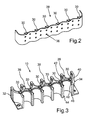
- an in Fig. 2 closer contact plate shown 28 which is made in the example of a bent sheet metal part.
- the contact plate 28 is an electrical guide element, via which an electric current can be dissipated from the round cells or guided to them.
- For contacting the contact plate 28 with the individual round cells 28 Mullellesslaschen 30 are formed on the contact plate.
- the magazine 10 is made in the example shown by molding the contact plate 28 by means of a plastic injection molding process.
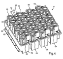
- Fig. 3 is the full magazine 10 alone again, without the round cells shown.
- Fig. 3 only the contact surface 32 is visible.
- the contact plate 28 For a better grip of the contact plate 28 in the surrounding plastic, the contact plate 28 through openings, of which for the sake of clarity in Fig. 2 only one through opening 36 is provided with a reference numeral.
- pins 38 are formed on the magazine, whose function below in connection with Fig. 5 is described.
- the round cell 12 is held (as well as the other round cells) in the magazine 10 by a snap connection.
- resilient walls 40, 42 are formed to hold the round cell 12 on the magazine 10.
- the round cell 12 was pressed against tapered surfaces 44, 46, whereby the walls 40, 42 have moved apart by elastic deformation and the round cell 12 is snapped between the walls 40, 42 in the magazine 10 ,
- a web 48 engages in an annular groove 50 of the round cell 12, whereby the round cell 12 is secured against slipping in the magazine 12 along its longitudinal axis 18.
- the round cells of the magazine 10 are to be installed in a housing for a traction battery 51 of a passenger car and interconnected to a parallel circuit.
- a parallel circuit the installation of the magazine 10 in connection with the assembly of the traction battery 51 based on Fig. 4 explained in more detail.
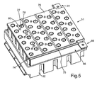
- the magazine 10 with the round cells has been inserted into a housing bottom 52 of the traction battery 51. Together with the magazine 10 in the example, three more magazines 54, 56, 58 of the same type as the magazine 10 arranged in the housing bottom 52. Overall, thus four double rows of round cells are present with each located between the rows of each double row contact plates.
- the end face 26 of the round cell 12 is arranged with end faces of the other round cells in a plane.
- the edge 24 of the cell cup 20 is electrically connected via a wire 60 to one of the contacting tabs 30.
- the wire 60 has been attached to the edge 24 and the contacting tab 30 in the example by means of a bonding method.
- the wire 60 also connects the edge of a cell cup of an opposite round cell 62 with the same contacting tab 30.
- the two round cells 12 and 62 are connected to the contacting tab 30 in one manufacturing step.
- the wire 60 is designed as an electrical fuse. In the event that an electric current of the round cell 12, which flows over the wire 60, exceeds a predetermined safety critical current value, the wire 60 melts, whereby the current flow is interrupted. As a result, damage to the round cell 12 or another component in the passenger car is avoided.
- the other round cells are connected by wires with respective Kunststoffmaschineschen.
- the wires can be poured over to protect against mechanical influences and against corrosion with a potting compound.
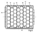
- a bus bar 66 electrically connects the pads 32, 64 to each other.
- the busbar 66 consists of a metal plate, which is made here for example of aluminum or copper.
- the busbar 66 is welded to the contact surfaces 32, 64 with the contact plates of the magazines 10, 54, 56, 58.
- a flange 68 is formed, via which the busbar 66 can be connected to a (not shown) cable of the passenger car or to another traction battery.
- the plus poles of the round cells i. the lid 22 of the round cell 12 and the lid of the other round cells, are electrically connected to each other via a further electrically conductive contact plate 70.
- the contact plate 70 has a flange 72, which serves as the flange 68 for connecting the contact plate 70 to a cable or another traction battery.
- an insulating plate 74 is fixed, which is placed on the end faces of the round cells.
- a collar 76 of the insulating plate 74 prevents electrical flashover from the contact plate 70 to the busbar 66th
- the contact plate 70 is wired by means of a bonding method with the individual lids of the round cells. For this purpose, the contact plate 70 and the insulating plate 74 connected to it holes. Through such a bore 78, a wire 80 is guided by the contact plate 70 to the lid 22.
- the contact plate 70 is held in the traction battery 51 by the magazines 10, 54, 56, 58.
- the contact plate 70 has been attached to the pins 38 of the magazine 10 and to corresponding pins of the remaining magazines 54, 56, 58. Subsequently, the pins 38 and the remaining pins have been deformed here by caulking and using hot gas, so that the contact plate firmly on the magazines 10, 54, 56, 58 sits.
- the traction battery 51 is closed.
- Fig. 6 the finished traction battery 51 is shown in a sectional view.
- the contact plate 28 of the magazine 10 and the contact plates of the remaining magazines 54, 56, 58 are each between two rows of round cells.
- the individual round cells are electrically connected to the flange 68 for connecting the traction battery 51 to the motor vehicle.
- the example shows how a low-cost battery for a motor vehicle can be provided.
Landscapes
- Chemical & Material Sciences (AREA)
- Chemical Kinetics & Catalysis (AREA)
- Electrochemistry (AREA)
- General Chemical & Material Sciences (AREA)
- Engineering & Computer Science (AREA)
- Manufacturing & Machinery (AREA)
- Battery Mounting, Suspending (AREA)
- Connection Of Batteries Or Terminals (AREA)
Description
- Die Erfindung betrifft eine Kraftfahrzeug-Batterie mit einer Mehrzahl von Batteriezellen, die in zumindest zwei Reihen achsparallel nebeneinander angeordnet sind und von denen zumindest einige über ein Leitelement elektrisch mit einem Anschlusselement verbunden sind, über welches die Batterie an das Kraftfahrzeug angeschlossen werden kann.
- Ein Kraftfahrzeug, wie z.B. ein Personkraftwagen, kann verschiedene Typen von Batterien aufweisen, beispielsweise eine Starter-Batterie oder eine Hochvolt-Traktionsbatterie. Im Zusammenhang mit der Erfindung ist mit dem Begriff Batterie ein Batterie beliebigen Typs gemeint. Unter einer Batterie wird auch eine wiederaufladbare Batterie, d.h. ein Akkumulator, verstanden.
- Die Erzeugung von elektrischer Energie erfolgt in einer Batterie durch eine oder mehrere galvanischen Zellen. Eine solche galvanische Zelle kann innerhalb der Batterie in einem in sich geschlossenen Behältnis bereitgestellt sein, das vorliegend als Batteriezelle bezeichnet wird. Bei der Herstellung einer Kraftfahrzeug-Batterie werden eine oder mehrere solcher Batteriezellen in einem Gehäuse der Batterie angeordnet und über elektrische Leiter miteinander verschaltet, so dass den Batteriezellen elektrische Energie entnommen und über die Anschlusselemente der Batterie z.B. einem Bordnetz des Kraftfahrzeugs zugeführt werden kann bzw. von dort in die Batteriezellen eingespeist werden kann.
- Die Herstellungskosten einer Batterie werden unter anderem durch den Aufwand bestimmt, der zum Verdrahten der Batteriezellen nötig ist. Aus der
US 7,671,565 B2 ist dazu bekannt, Rundzellen in einer Batterie achsparallel nebeneinander zwischen zwei gelochten, elektrisch leitenden Platten anzuordnen. Durch die Löcher der Platten hindurch kann die Platte dann mit jeweiligen Anschlusspolen (Plus-Pol und Minus-Pol) an den Stirnseiten der Rundzellen elektrisch verbunden werden. - Eine Batterie muss in einem Massenfertigungsprozess kostengünstig und dennoch mit hoher Zuverlässigkeit fehlerfrei herstellbar sein.
- In der
EP 2 613 379 A1 und dem DokumentWO 2012/029235 A1 ist eine Batterie mit parallel nebeneinander angeordneten Rundzellen beschrieben, die untereinander durch zwei Platten elektrisch parallel geschaltet sind. Jede der Platten liegt jeweils an einem Ende der zylindrischen Rundzellen auf. Damit die Rundzellen zwischen den Platten nicht verrutschen, können die Platten jeweils Vertiefungen aufweisen, in welche jeweils eine der Rundzellen angeordnet ist. Indem jede der Platten direkt auf einem Anschlusskontakt der Rundzellen aufliegt, sind die Rundzellen ohne weitere Kontaktiermittel direkt mit den beiden Platten elektrisch verbunden. Eine Batterie mit einem ähnlichen Leitelement wie in derEP 2 613 378 ist in dem DokumentUS 2008241667 offenbart. - Es ist Aufgabe der vorliegenden Erfindung, eine kostengünstig herstellbare Batterie für ein Kraftfahrzeug bereitzustellen.
- Die Aufgabe wird durch eine Batterie gemäß Anspruch 1 gelöst. Vorteilhafte Weiterbildungen der Erfindung sind durch die Unteransprüche gegeben.
- Die erfindungsgemäße Kraftfahrzeug-Batterie umfasst eine Mehrzahl von Batteriezellen. Bevorzugt sind Rundzellen verwendet. Allgemein handelt es sich aber bei den Batteriezellen der erfindungsgemäßen Batterie um Batteriezellen, von denen jede eine durch eine Grundform der Batteriezelle vorgegebene Längsachse aufweist. Im Falle einer Rundzelle ist die Längsachse entsprechend durch die Symmetrieachse ihrer zylindrischen Grundform gebildet. Zumindest ein Anschlusspol (Plus- oder Minus-Pol) jeder Batteriezelle befindet sich an einer jeweiligen Stirnseite, die sich quer zur Längsachse der Batteriezelle erstreckt. Bei der erfindungsgemäßen Batterie sind die Batteriezellen achsparallel nebeneinander in zumindest zwei Reihen angeordnet, so dass die Stirnseiten der Batteriezellen von einer gemeinsamen Seite her zugänglich sind. Die erfindungsgemäße Batterie weist zudem ein elektrisches Leitelement (z.B. eine Platte) auf, die zumindest bereichsweise zwischen den beiden Reihen angeordnet ist. Über das Leitelement ist jeweils ein Anschlusspol der Batteriezellen von zumindest einer der beiden Reihen mit einem Anschlusselement der Batterie elektrisch verbunden. Mit dem Anschlusselement ist ein Element gemeint, über das die Batterie an das Kraftfahrzeug angeschlossen werden kann.
- Die erfindungsgemäße Batterie weist zwei besondere Vorteile auf. Bei der Herstellung der Batterie werden durch Anordnen des Leitelements zwischen den Batteriezellen nicht die Bewegungen eines Werkzeugs zum Verdrahten der Batteriezellen behindert. Im Betrieb der Batterie wird über das Leitelement Wärme aus den Batteriezellen an eine Umgebung der Batterie abgeführt.
- Eine besonders einfache und damit kostengünstige Bauweise der Batterie ergibt sich, wenn das Leitelement eine elektrisch leitende Platte umfasst. Eine Flächennormale der Platte steht dabei senkrecht zu den Längsachsen der Batteriezellen.
- Das Leitelement, also z.B. die elektrisch leitende Platte, weist zumindest einen Anschlussbereich auf, in welchem ein elektrisches Koppelelement zum elektrischen Verbinden des Leitelements mit zumindest einem der Anschlusspole befestigt ist. Das Koppelelement kann z.B. ein Bonddraht sein, der mittels eines entsprechenden Bonding-Verfahrens am Leitelement angebracht ist. Durch Ausbilden von entsprechenden Anschlussbereichen am Leitelement wird eine automatisierte Herstellung der Batterie ermöglicht.
- Bei einer anderen Weiterbildung der erfindungsgemäßen Batterie ist zusätzlich auch jeweils ein Anschlusspol der Batteriezellen der anderen Batteriezellen-Reihe über das Leitelement mit dem Anschlusselement der Batterie elektrisch verbunden. So kann über das Leitelement Strom aus den Batteriezellen beiderseits des Leitelements entnommen bzw. diesen zugeführt werden. Mit einem einzigen Leitelement sind somit in vorteilhafter Weise zwei Reihen von Batteriezellen verschaltet. Zudem lässt sich eine besonders geringe Fertigungszeit der Batterie ermöglichen, wenn jeweils eine Batteriezelle einer Reihe zusammen mit einer ihr auf der anderen Seite des Leitelements gegenüber befindlichen Batteriezelle der anderen Reihe an einem gemeinsamen Anschlussbereich des zwischen ihnen befindlichen Leitelements angeschlossen wird. Dann können mittels eines einzigen Drahtes z.B. durch ein Bonding-Verfahren beide Batteriezellen mit dem Leitelement elektrisch verbunden werden.
- Bei der erfindungsgemäßen Batterie ist es möglich, weitere Doppelreihen von Batteriezellen vorzusehen, zwischen denen sich jeweils ein weiteres Leitelement der genannten Art befindet. In diesem Zusammenhang kann dann vorgesehen sein, eine Sammelschiene vorzusehen, über welche die Leitelemente gemeinsam mit dem Anschlusselement der Batterie elektrisch gekoppelt sind.
- Eine andere vorteilhafte Weiterbildung der erfindungsgemäßen Batterie sieht vor, das Leitelement als einen Bestandteil eines Halteelements auszubilden, in welches die Batteriezellen eingesetzt und durch welches die Batteriezellen in einem Gehäuse der Batterie gehalten sind. Ein solches Halteelement oder Magazin, in welches mehrere Batteriezellen bei der Montage einer erfindungsgemäßen Batterie eingesetzt werden können, um dann gemeinsam in das Gehäuse eingesetzt zu werden, ermöglicht eine Verringerung der Anzahl der Montageschritte zur Herstellung der Batterie und damit auch deren Herstellungskosten. Zudem ist durch die feste Verbindung des Leitelements mit dem Haltelement zum Halten der Batteriezellen sichergestellt, dass das Leitelement und die Batteriezellen gegeneinander fixiert sind. Dadurch ist in vorteilhafter Weise vermieden, dass die elektrischen Verbindungen zwischen dem Leitelement und den Batteriezellen brechen, wenn die Batterie bei einer Fahrt des Kraftfahrzeugs erschüttert wird.
- Bei einer anderen Weiterbildung der erfindungsgemäßen Batterie ist bei den Batteriezellen jeweils ein weiterer Anschlusspol an der Stirnseite bereitgestellt. Dadurch ergibt sich der Vorteil, dass bei der Herstellung der Batterie sowohl der Plus- als auch der Minus-Pol der Batteriezellen von derselben Seite her verschaltet werden können. Dies vereinfacht eine automatisierte Herstellung mit einem robotergeführten Werkzeug.
- Sind die Stirnseiten in einer gemeinsamen Ebene angeordnet, erlaubt dies besonders schnelle Bewegungen des Werkzeugs, was eine besonders kurze Herstellungsdauer ermöglicht.
- Als ein zweites Leitelement zum Ermöglichen eines geschlossenen Stromkreises kann eine elektrisch leitende Platte bereitgestellt sein, welche parallel zu den Stirnseiten der Batteriezellen angeordnet ist. Mit anderen Worten werden die Reihen von Batteriezellen von ihren Stirnseiten her von der Platte abgedeckt. Die Flächennormale der Platte ist dann parallel zu den Längsachsen der Batteriezellen ausgerichtet. Die Platte ist dabei mit jeweils einem Anschlusspol der Batteriezellen elektrisch verbunden. Ein Stromfluss in einem Stromkreis ist dann über das Leitelement zwischen den Batteriezellen einerseits und die Platte auf den Stirnseiten der Batteriezellen andererseits ermöglicht.
- Die Batteriezellen sind dabei bevorzugt zu einer Parallelschaltung verschaltet. Mittels der erfindungsgemäßen Batterie können die dabei entstehenden Ströme hoher Stromstärke problemlos über das zwischen den Reihen der Batteriezellen befindlichen Leitelement geführt werden.
- Die Erfindung wird im Folgenden anhand eines Ausführungsbeispiels näher erläutert. Dazu zeigt:
- Fig. 1
- eine perspektivische Darstellung eines Magazins mit darin eingesetzten Rundzellen für eine Batterie gemäß einer Ausführungsform der Erfindung;
- Fig. 2
- eine perspektivische Darstellung einer Kontaktplatte, die Bestandteil des in
Fig. 1 gezeigten Magazins ist; - Fig. 3
- eine perspektivische Darstellung des Magazins aus
Fig. 1 ohne die Rundzellen; - Fig. 4
- eine perspektivische Darstellung einer Batterie, in welche das Magazin aus
Fig. 1 eingesetzt ist; - Fig. 5
- eine perspektivische Darstellung der Batterie aus
Fig. 4 mit einer auf die Rundzellen aufgesetzten Kontaktplatte zum Anschließen von Plus-Polen der Rundzellen und mit einer Sammelschiene; und - Fig. 6
- eine schematische Darstellung eines Schnitts durch die Batterie, wie sie in
Fig. 5 dargestellt ist. - Das Beispiel stellt eine bevorzugte Ausführungsform der Erfindung dar.
- In
Fig. 1 ist ein Magazin 10 mit elf darin einsetzten Rundzellen gezeigt, von denen der Übersichtlichkeit halber nur eine Rundzelle 12 mit einem Bezugszeichen versehen ist. Die Rundzellen sind in dem Magazin nebeneinander in zwei Reihen 14 und 16 aufgereiht. Die Rundzelle 12 weist (wie auch die übrigen Rundzellen) eine längliche, zylindrische Grundform auf. Eine Symmetrieachse bzw. Längsachse 18 der Rundzelle 12 ist parallel zu entsprechenden Längsachsen der übrigen Rundzellen ausgerichtet. - Die Rundzelle 12 enthält eine galvanische Zelle zum Speichern von elektrochemischer Energie. Ein Zellenbecher 20 der Rundzelle 12 bildet einen Minus-Pol, ein Deckel 22 einen Plus-Pol. Der Deckel 22 und ein oberer Rand 24 des Zellenbechers 20 bilden eine Stirnseite 26 der Rundzelle 12. Sowohl der Minus-Pol (Zellenbecher 20) als auch der Plus-Pol (Deckel 22) können über die Stirnseite 26 elektrisch kontaktiert werden.
- Zum Verschalten der Minus-Pole der Rundzellen für eine Parallelschaltung der Rundzellen befindet sich zwischen den beiden Reihen 14 und 16 von Rundzellen in dem Magazin 10 eine in
Fig. 2 genauer gezeigte Kontaktplatte 28, die in dem Beispiel aus einem Blechbiegeteil gefertigt ist. Die Kontaktplatte 28 ist ein elektrisches Leitelement, über welches ein elektrischer Strom von den Rundzellen abgeführt oder zu diesen hingeführt werden kann. Zum Kontaktieren der Kontaktplatte 28 mit den einzelnen Rundzellen sind an der Kontaktplatte 28 Kontaktierungslaschen 30 ausgebildet. - Das Magazin 10 ist in dem gezeigten Beispiel durch Umspritzen der Kontaktplatte 28 mittels eines Kunststoff-Spritzgussverfahrens hergestellt. In
Fig. 3 ist das vollständige Magazin 10 noch einmal allein, ohne die Rundzellen dargestellt. Von der Kontaktplatte 28 sind neben den Kontaktierungslaschen 30 noch zwei Kontaktflächen 32 und 34 freigelassen, über welche die Kontaktplatte 28 von außerhalb des Magazins 10 elektrisch kontaktiert werden kann. InFig. 3 ist nur die Kontaktfläche 32 sichtbar. - Für einen besseren Halt der Kontaktplatte 28 in dem sie umgebenden Kunststoff weist die Kontaktplatte 28 Durchgangsöffnungen auf, von denen der Übersichtlichkeit halber in
Fig. 2 nur eine Durchgangsöffnung 36 mit einem Bezugszeichen versehen ist. - Mittels des Spritzgussverfahrens sind an dem Magazin 10 Stifte 38 angeformt, deren Funktion weiter unten im Zusammenhang mit
Fig. 5 beschrieben ist. - Die Rundzelle 12 ist (wie auch die übrigen Rundzellen) in dem Magazin 10 durch eine Schnappverbindung gehalten. Dazu sind zum Halten der Rundzelle 12 an dem Magazin 10 elastische Wände 40, 42 ausgebildet. Zum Einsetzen der Rundzelle 12 in das Magazin 10 wurde die Rundzelle 12 gegen konisch zulaufende Flächen 44, 46 gedrückt, wodurch sich die Wände 40, 42 durch elastische Verformung auseinanderbewegt haben und die Rundzelle 12 zwischen den Wänden 40, 42 in dem Magazin 10 eingeschnappt ist. Ein Steg 48 greift in eine Ringnut 50 der Rundzelle 12, wodurch die Rundzelle 12 gegen ein Verrutschen in dem Magazin 12 entlang ihrer Längsachse 18 gesichert ist.
- Die Rundzellen des Magazins 10 sollen in ein Gehäuse für eine Traktionsbatterie 51 eines Personenkraftwagens eingebaut und zu einer Parallelschaltung verschaltet werden. Im Folgenden wird dazu der Einbau des Magazins 10 im Zusammenhang mit der Montage der Traktionsbatterie 51 anhand von
Fig. 4 näher erläutert. - Das Magazin 10 mit den Rundzellen ist in einen Gehäuseboden 52 der Traktionsbatterie 51 eingesetzt worden. Zusammen mit dem Magazin 10 in dem Beispiel noch drei weitere Magazine 54, 56, 58 derselben Bauart wie das Magazin 10 in dem Gehäuseboden 52 angeordnet. Insgesamt sind somit vier Doppelreihen von Rundzellen mit jeweils zwischen den Reihen einer jeden Doppelreihe befindlichen Kontaktplatten vorhanden.
- Die Stirnseite 26 der Rundzelle 12 ist mit Stirnseiten der übrigen Rundzellen in einer Ebene angeordnet. Der Rand 24 des Zellenbechers 20 ist über einen Draht 60 mit einer der Kontaktierungslaschen 30 elektrisch verbunden. Der Draht 60 ist in dem Beispiel mittels eines Bonding-Verfahrens an dem Rand 24 und der Kontaktierungslasche 30 befestigt worden. Der Draht 60 verbindet auch den Rand eines Zellenbechers einer gegenüberliegenden Rundzelle 62 mit derselben Kontaktierungslasche 30. So wurden durch Bonden des einzelnen Drahtes 60 die beiden Rundzellen 12 und 62 in einem Fertigungsschritt mit der Kontaktierungslasche 30 verbunden.
- Der Draht 60 ist als elektrische Sicherung ausgelegt. Für den Fall, dass ein elektrischer Strom der Rundzelle 12, der über den Draht 60 fließt, einen vorbestimmten sicherheitskritischen Stromstärkewert überschreitet, schmilzt der Draht 60, wodurch der Stromfluss unterbrochen wird. Dadurch wird eine Beschädigung der Rundzelle 12 oder eines anderen Bauteils in dem Personenkraftwagen vermieden.
- Wie in
Fig. 4 gezeigt ist, sind auch die übrigen Rundzellen durch Drähte mit jeweiligen Kontaktierungslaschen verbunden. Die Drähte können zum Schutz gegen mechanische Einflüsse und gegen Korrosion mit einer Vergussmasse übergossen sein. - Über die Kontaktfläche 32 der Kontaktplatte 28 und entsprechende Kontaktflächen 64 der Kontaktplatten der übrigen Magazine 54, 56, 58 soll ein jeweiliger Sammelstrom von den Kontaktplatten abgegriffen werden.
- In
Fig. 5 ist dazu die weitere Verschaltung der Rundzellen gezeigt. Eine Sammelschiene 66 verbindet die Kontaktflächen 32, 64 elektrisch miteinander. Die Sammelschiene 66 besteht aus einer Metallplatte, die hier beispielsweise aus Aluminium oder Kupfer gefertigt ist. Die Sammelschiene 66 ist an den Kontaktflächen 32, 64 mit den Kontaktplatten der Magazine 10, 54, 56, 58 verschweißt. - An der Sammelschiene 66 ist ein Flansch 68 ausgebildet, über den die Sammelschiene 66 an ein (nicht dargestelltes) Kabel des Personenkraftwagens oder an eine weitere Traktionsbatterie angeschlossen werden kann.
- Die Plus-Pole der Rundzellen, d.h. der Deckel 22 der Rundzelle 12 und die Deckel der übrigen Rundzellen, sind über eine weitere elektrisch leitende Kontaktplatte 70 miteinander elektrisch verbunden.
- Die Kontaktplatte 70 weist einen Flansch 72 auf, der wie der Flansch 68 zum Anschließen der Kontaktplatte 70 an ein Kabel oder eine weitere Traktionsbatterie dient.
- An einer in
Fig. 5 unteren Seite der Kontaktplatte 70 ist eine Isolierplatte 74 befestigt, die auf die Stirnseiten der Rundzellen aufgelegt ist. Ein Kragen 76 der Isolierplatte 74 verhindert einen elektrischen Überschlag von der Kontaktplatte 70 zur Sammelschiene 66. - Die Kontaktplatte 70 ist mittels eines Bonding-Verfahrens mit den einzelnen Deckeln der Rundzellen verdrahtet. Dazu weist die Kontaktplatte 70 und die mit ihr verbundene Isolierplatte 74 Bohrungen auf. Durch eine solche Bohrung 78 ist ein Draht 80 von der Kontaktplatte 70 zum Deckel 22 geführt.
- Die Kontaktplatte 70 ist in der Traktionsbatterie 51 durch die Magazine 10, 54, 56, 58 gehalten. Dazu ist die Kontaktplatte 70 auf die Stifte 38 des Magazins 10 und auf entsprechende Stifte der übrigen Magazine 54, 56, 58 aufgesteckt worden. Anschließend sind die Stifte 38 und die übrigen Stifte hier durch Verstemmen und unter Verwendung von heißem Gas verformt worden, so dass die Kontaktplatte fest auf den Magazinen 10, 54, 56, 58 sitzt.
- Durch Aufsetzten eines (nicht dargestellten) Gehäusedeckels auf den Gehäuseboden 52 wird die Traktionsbatterie 51 verschlossen.
- In
Fig. 6 ist die fertige Traktionsbatterie 51 in einer Schnittansicht gezeigt. Die Kontaktplatte 28 des Magazins 10 und die Kontaktplatten der übrigen Magazine 54, 56, 58 befinden sich jeweils zwischen zwei Reihen von Rundzellen. Über die Kontaktplatten und die Sammelschiene 66 sind die einzelnen Rundzellen mit der Flansch 68 zum Anschließen der Traktionsbatterie 51 an das Kraftfahrzeug elektrisch verbunden. - Durch das Beispiel ist gezeigt, wie eine kostengünstige Batterie für einen Kraftwagen bereitgestellt werden kann.
Claims (10)
- Batterie (51) für ein Kraftfahrzeug, mit einer Mehrzahl von Batteriezellen (12, 62), von denen jede eine durch eine Grundform der jeweiligen Batteriezelle (12, 62) vorgegebene Längsachse (18) und eine sich quer zur Längsachse (18) erstreckende Stirnseite (26) mit zumindest einem Anschlusspol (22, 24) aufweist, wobei die Batteriezellen (12, 62) achsparallel nebeneinander in zumindest zwei Reihen (14, 16) angeordneten sind und ein elektrisches Leitelement (28), über welches jeweils ein Anschlusspol (24) der Batteriezellen (12, 62) zumindest einer der beiden Reihen (14, 16) mit einem Anschlusselement (68) zum Anschließen der Batterie (51) an das Kraftfahrzeug elektrisch verbunden ist, und welches zumindest einen Anschlussbereich (30) aufweist, in welchem ein elektrisches Koppelelement (60) zum elektrischen Verbinden des Leitelements (28) mit zumindest einem der Anschlusspole (24) befestigt ist.
dadurch gekennzeichnet, dass das elektrische Leitelement (28) zumindest bereichsweise zwischen den beiden Reihen (14, 16) angeordnet ist. - Batterie (51) nach Anspruch 1, wobei das Leitelement (28) eine elektrisch leitende Platte umfasst.
- Batterie (51) nach einem der vorhergehenden Ansprüche, wobei zusätzlich auch jeweils ein Anschlusspol der Batteriezellen (62) der anderen Reihe (14) über das Leitelement (28) mit dem Anschlusselement (68) der Batterie (51) elektrisch verbunden ist.
- Batterie (51) nach einem der vorhergehenden Ansprüche, wobei das Leitelement (28) über eine Sammelschiene (66) mit dem Anschlusselement (68) elektrisch gekoppelt ist.
- Batterie (51) nach einem der vorhergehenden Ansprüche, wobei das Leitelement (28) ein Bestandteil eines Halteelements (10) ist, in welches die Batteriezellen (12, 62) eingesetzt und durch welches sie in einem Gehäuse (52) der Batterie (51) gehalten sind.
- Batterie (51) nach einem der vorhergehenden Ansprüche, wobei die Batteriezellen (12, 62) Rundzellen sind.
- Batterie (51) nach einem der vorhergehenden Ansprüche, wobei bei den Batteriezellen (12, 62) jeweils ein weiterer Anschlusspol (22) an der Stirnseite (26) bereitgestellt ist.
- Batterie (51) nach einem der vorhergehenden Ansprüche, wobei die Stirnseiten (26) in einer gemeinsamen Ebene angeordnet sind.
- Batterie (51) nach einem der vorhergehenden Ansprüche, wobei eine elektrisch leitende Platte (70) als zweites Leitelement bereitgestellt ist, welche parallel zu den Stirnseiten (26) der Batteriezellen angeordnet ist, wobei jeweils ein Anschlusspol (22) der Batteriezellen (12, 62) mit der Platte (70) elektrisch verbunden ist.
- Batterie (51) nach einem der vorhergehenden Ansprüche, wobei die Batteriezellen (12, 62) zu einer Parallelschaltung verschaltet sind.
Applications Claiming Priority (2)
| Application Number | Priority Date | Filing Date | Title |
|---|---|---|---|
| DE102011015622.4A DE102011015622B4 (de) | 2011-03-31 | 2011-03-31 | Batterie für ein Kraftfahrzeug |
| PCT/EP2012/001302 WO2012130424A1 (de) | 2011-03-31 | 2012-03-24 | Batterie für ein kraftfahrzeug |
Publications (2)
| Publication Number | Publication Date |
|---|---|
| EP2692001A1 EP2692001A1 (de) | 2014-02-05 |
| EP2692001B1 true EP2692001B1 (de) | 2015-12-16 |
Family
ID=46022147
Family Applications (1)
| Application Number | Title | Priority Date | Filing Date |
|---|---|---|---|
| EP12717593.3A Not-in-force EP2692001B1 (de) | 2011-03-31 | 2012-03-24 | Batterie für ein kraftfahrzeug |
Country Status (3)
| Country | Link |
|---|---|
| EP (1) | EP2692001B1 (de) |
| DE (1) | DE102011015622B4 (de) |
| WO (1) | WO2012130424A1 (de) |
Families Citing this family (17)
| Publication number | Priority date | Publication date | Assignee | Title |
|---|---|---|---|---|
| DE102013203280A1 (de) | 2013-02-27 | 2014-08-28 | Bayerische Motoren Werke Aktiengesellschaft | Hochvolt-Energiespeichermodul und Verfahren zur Herstellung des Hochvolt-Energiespeichermoduls |
| JP6246483B2 (ja) * | 2013-04-04 | 2017-12-13 | 株式会社マキタ | 電動工具用電池パック |
| DE102013017168B4 (de) * | 2013-10-16 | 2017-07-13 | Lisa Dräxlmaier GmbH | Vorrichtung zum elektrischen Verbinden mehrerer Rundzellen sowie dazugehöriges Batteriemodul und Verfahren |
| KR102236981B1 (ko) * | 2016-03-16 | 2021-04-05 | 엘에스엠트론 주식회사 | 에너지 저장 모듈용 연결 구조체 |
| DE102017004939A1 (de) | 2017-05-23 | 2018-07-26 | Daimler Ag | Verfahren zum elektrisch leitenden Verbinden der elektrischen Pole wenigstens zweier Batteriezellen einer Batterie und Batterie für ein Kraftfahrzeug mit wenigstens zwei Batteriezellen |
| WO2018234722A1 (en) | 2017-06-19 | 2018-12-27 | Tti (Macao Commercial Offshore) Limited | SURFACE CLEANING APPARATUS |
| DE202017103801U1 (de) * | 2017-06-26 | 2018-11-08 | SOLO Vertriebs- und Entwicklungs-GmbH | Halteelement für eine Batteriezellenanordnung |
| DE102018112475B4 (de) * | 2018-05-24 | 2024-01-18 | Lisa Dräxlmaier GmbH | Batterieanordnung und herstellverfahren |
| DE102019130854A1 (de) * | 2019-03-18 | 2020-09-24 | Dr. Ing. H.C. F. Porsche Aktiengesellschaft | Haltevorrichtung für Strom- und Signalleiter einer Traktionsbatterie eines Kraftfahrzeugs |
| KR102937187B1 (ko) * | 2020-05-19 | 2026-03-09 | 주식회사 엘지에너지솔루션 | 배터리 모듈, 이를 포함하는 배터리 팩, 및 자동차 |
| CN218677373U (zh) * | 2021-08-26 | 2023-03-21 | 江苏东成工具科技有限公司 | 电池包 |
| DE102021125014A1 (de) | 2021-09-28 | 2023-03-30 | Bayerische Motoren Werke Aktiengesellschaft | Batteriezellengehäuse für eine Batteriezelle eines elektrischen Energiespeichers, Batteriezelle, elektrischer Energiespeicher sowie Verfahren |
| DE102022128743A1 (de) | 2022-10-28 | 2024-05-08 | Man Truck & Bus Se | Trägervorrichtung für Batterierundzellen |
| CN116053691B (zh) * | 2023-01-10 | 2024-02-23 | 铁塔能源有限公司 | 一种电芯固定支架、电池模组及车辆 |
| DE102023101421A1 (de) | 2023-01-20 | 2024-07-25 | Man Truck & Bus Se | Batteriemodul und Verfahren zur Herstellung eines Batteriemoduls |
| DE102024128969A1 (de) * | 2024-10-08 | 2026-04-09 | Bayerische Motoren Werke Aktiengesellschaft | Trägereinrichtung für Batteriezellen für einen Hochvoltspeicher |
| DE102024129950A1 (de) * | 2024-10-16 | 2026-04-16 | Dr. Ing. H.C. F. Porsche Aktiengesellschaft | Halterahmenanordnung für Batteriezellen sowie eine Energiespeicheranordnung |
Citations (1)
| Publication number | Priority date | Publication date | Assignee | Title |
|---|---|---|---|---|
| WO2012029235A1 (ja) * | 2010-08-31 | 2012-03-08 | パナソニック株式会社 | 組電池 |
Family Cites Families (6)
| Publication number | Priority date | Publication date | Assignee | Title |
|---|---|---|---|---|
| US7671565B2 (en) | 2006-02-13 | 2010-03-02 | Tesla Motors, Inc. | Battery pack and method for protecting batteries |
| US9034501B2 (en) * | 2007-02-16 | 2015-05-19 | Panasonic Intellectual Property Management Co., Ltd. | Electric storage unit |
| US7923144B2 (en) * | 2007-03-31 | 2011-04-12 | Tesla Motors, Inc. | Tunable frangible battery pack system |
| DE102007044461A1 (de) * | 2007-09-11 | 2009-03-12 | Daimler Ag | Wärmeaustauschereinheit und Elektrochemischer Energiespeicher mit einer Wärmeaustauschereinheit |
| JP5451211B2 (ja) * | 2009-06-26 | 2014-03-26 | パナソニック株式会社 | 蓄電ユニット |
| DE102010045707B4 (de) * | 2010-09-16 | 2018-07-05 | Fey Elektronik Gmbh | Batteriepack |
-
2011
- 2011-03-31 DE DE102011015622.4A patent/DE102011015622B4/de not_active Expired - Fee Related
-
2012
- 2012-03-24 WO PCT/EP2012/001302 patent/WO2012130424A1/de not_active Ceased
- 2012-03-24 EP EP12717593.3A patent/EP2692001B1/de not_active Not-in-force
Patent Citations (2)
| Publication number | Priority date | Publication date | Assignee | Title |
|---|---|---|---|---|
| WO2012029235A1 (ja) * | 2010-08-31 | 2012-03-08 | パナソニック株式会社 | 組電池 |
| EP2613379A1 (de) * | 2010-08-31 | 2013-07-10 | Panasonic Corporation | Montierte batterie |
Also Published As
| Publication number | Publication date |
|---|---|
| DE102011015622B4 (de) | 2017-01-05 |
| DE102011015622A1 (de) | 2012-10-04 |
| EP2692001A1 (de) | 2014-02-05 |
| WO2012130424A1 (de) | 2012-10-04 |
Similar Documents
| Publication | Publication Date | Title |
|---|---|---|
| DE102011015622B4 (de) | Batterie für ein Kraftfahrzeug | |
| DE102017216869B4 (de) | Sammelschienenmodul | |
| EP3523841B1 (de) | Energiespeichermodul und verfahren zum zusammenbau | |
| EP2639857B1 (de) | Verbindungssystem für eine Energiespeichereinrichtung und Energiespeichereinrichtung mit dem Verbindungssystem | |
| DE112014006004B4 (de) | Verfahren zur Herstellung eines Batterieverdrahtungsmoduls | |
| DE102015225233A1 (de) | Batterieleitungsmodul und Batterieleitungsmodulherstellungsverfahren | |
| DE19611776A1 (de) | Batterie | |
| DE102018212913A1 (de) | Leitermodul | |
| DE112014006079B4 (de) | Verfahren zum Herstellen eines Batterieverdrahtungsmoduls | |
| DE102013209358A1 (de) | Verfahren zur herstellung einer elektrischen speichervorrichtung, abstandselement und elektrische speichervorrichtung | |
| DE102017221535A1 (de) | Befestigungsstruktur einer Leitereinheit | |
| DE102011087040A1 (de) | Zellkontaktieranordnung für einen Energiespeicher | |
| DE102010046642A1 (de) | Elektrischer Energiespeicher sowie Leiterelement für einen solchen Energiespeicher | |
| EP2692000B1 (de) | Batterie für ein kraftfahrzeug und zugehöriges herstellungsverfahren | |
| WO2020078649A1 (de) | Schutzeinheit für ein batteriemodul einer hochvoltbatterie, batteriemodul sowie hochvoltbatterie | |
| WO2011060969A1 (de) | Batteriezellenverbinder | |
| EP3631877B1 (de) | Energiespeichermodul und verfahren zum zusammenbau davon | |
| DE112020000962T5 (de) | Energiespeichervorrichtung | |
| WO2015074735A1 (de) | Batterie mit einer mehrzahl von batteriezellen wobei die pole mittels verbindungselemente verbunden sind | |
| DE112017001046T5 (de) | Leitermodul | |
| EP2735039B1 (de) | Zellkontaktieranordnung für einen energiespeicher | |
| EP2791996B1 (de) | Batterie für ein kraftfahrzeug | |
| DE112017006651T5 (de) | Energiespeichervorrichtung | |
| EP3063808B1 (de) | Elektrochemischer akkumulator | |
| DE112015000905T5 (de) | Stromquellenvorrichtung |
Legal Events
| Date | Code | Title | Description |
|---|---|---|---|
| PUAI | Public reference made under article 153(3) epc to a published international application that has entered the european phase |
Free format text: ORIGINAL CODE: 0009012 |
|
| 17P | Request for examination filed |
Effective date: 20131031 |
|
| AK | Designated contracting states |
Kind code of ref document: A1 Designated state(s): AL AT BE BG CH CY CZ DE DK EE ES FI FR GB GR HR HU IE IS IT LI LT LU LV MC MK MT NL NO PL PT RO RS SE SI SK SM TR |
|
| DAX | Request for extension of the european patent (deleted) | ||
| 17Q | First examination report despatched |
Effective date: 20150330 |
|
| REG | Reference to a national code |
Ref country code: DE Ref legal event code: R079 Ref document number: 502012005497 Country of ref document: DE Free format text: PREVIOUS MAIN CLASS: H01M0002100000 Ipc: H01M0010655300 |
|
| RIC1 | Information provided on ipc code assigned before grant |
Ipc: H01M 2/20 20060101ALI20150729BHEP Ipc: H01M 2/10 20060101ALI20150729BHEP Ipc: H01M 10/6555 20140101ALI20150729BHEP Ipc: H01M 10/6553 20140101AFI20150729BHEP |
|
| GRAP | Despatch of communication of intention to grant a patent |
Free format text: ORIGINAL CODE: EPIDOSNIGR1 |
|
| INTG | Intention to grant announced |
Effective date: 20150904 |
|
| GRAS | Grant fee paid |
Free format text: ORIGINAL CODE: EPIDOSNIGR3 |
|
| GRAA | (expected) grant |
Free format text: ORIGINAL CODE: 0009210 |
|
| AK | Designated contracting states |
Kind code of ref document: B1 Designated state(s): AL AT BE BG CH CY CZ DE DK EE ES FI FR GB GR HR HU IE IS IT LI LT LU LV MC MK MT NL NO PL PT RO RS SE SI SK SM TR |
|
| REG | Reference to a national code |
Ref country code: GB Ref legal event code: FG4D Free format text: NOT ENGLISH |
|
| REG | Reference to a national code |
Ref country code: CH Ref legal event code: EP |
|
| REG | Reference to a national code |
Ref country code: IE Ref legal event code: FG4D Free format text: LANGUAGE OF EP DOCUMENT: GERMAN |
|
| REG | Reference to a national code |
Ref country code: AT Ref legal event code: REF Ref document number: 765949 Country of ref document: AT Kind code of ref document: T Effective date: 20160115 |
|
| REG | Reference to a national code |
Ref country code: DE Ref legal event code: R096 Ref document number: 502012005497 Country of ref document: DE |
|
| REG | Reference to a national code |
Ref country code: FR Ref legal event code: PLFP Year of fee payment: 5 |
|
| REG | Reference to a national code |
Ref country code: NL Ref legal event code: MP Effective date: 20151216 |
|
| REG | Reference to a national code |
Ref country code: LT Ref legal event code: MG4D |
|
| PG25 | Lapsed in a contracting state [announced via postgrant information from national office to epo] |
Ref country code: HR Free format text: LAPSE BECAUSE OF FAILURE TO SUBMIT A TRANSLATION OF THE DESCRIPTION OR TO PAY THE FEE WITHIN THE PRESCRIBED TIME-LIMIT Effective date: 20151216 Ref country code: LT Free format text: LAPSE BECAUSE OF FAILURE TO SUBMIT A TRANSLATION OF THE DESCRIPTION OR TO PAY THE FEE WITHIN THE PRESCRIBED TIME-LIMIT Effective date: 20151216 Ref country code: NO Free format text: LAPSE BECAUSE OF FAILURE TO SUBMIT A TRANSLATION OF THE DESCRIPTION OR TO PAY THE FEE WITHIN THE PRESCRIBED TIME-LIMIT Effective date: 20160316 |
|
| PG25 | Lapsed in a contracting state [announced via postgrant information from national office to epo] |
Ref country code: SE Free format text: LAPSE BECAUSE OF FAILURE TO SUBMIT A TRANSLATION OF THE DESCRIPTION OR TO PAY THE FEE WITHIN THE PRESCRIBED TIME-LIMIT Effective date: 20151216 Ref country code: RS Free format text: LAPSE BECAUSE OF FAILURE TO SUBMIT A TRANSLATION OF THE DESCRIPTION OR TO PAY THE FEE WITHIN THE PRESCRIBED TIME-LIMIT Effective date: 20151216 Ref country code: FI Free format text: LAPSE BECAUSE OF FAILURE TO SUBMIT A TRANSLATION OF THE DESCRIPTION OR TO PAY THE FEE WITHIN THE PRESCRIBED TIME-LIMIT Effective date: 20151216 Ref country code: GR Free format text: LAPSE BECAUSE OF FAILURE TO SUBMIT A TRANSLATION OF THE DESCRIPTION OR TO PAY THE FEE WITHIN THE PRESCRIBED TIME-LIMIT Effective date: 20160317 Ref country code: LV Free format text: LAPSE BECAUSE OF FAILURE TO SUBMIT A TRANSLATION OF THE DESCRIPTION OR TO PAY THE FEE WITHIN THE PRESCRIBED TIME-LIMIT Effective date: 20151216 Ref country code: NL Free format text: LAPSE BECAUSE OF FAILURE TO SUBMIT A TRANSLATION OF THE DESCRIPTION OR TO PAY THE FEE WITHIN THE PRESCRIBED TIME-LIMIT Effective date: 20151216 |
|
| PG25 | Lapsed in a contracting state [announced via postgrant information from national office to epo] |
Ref country code: ES Free format text: LAPSE BECAUSE OF FAILURE TO SUBMIT A TRANSLATION OF THE DESCRIPTION OR TO PAY THE FEE WITHIN THE PRESCRIBED TIME-LIMIT Effective date: 20151216 Ref country code: CZ Free format text: LAPSE BECAUSE OF FAILURE TO SUBMIT A TRANSLATION OF THE DESCRIPTION OR TO PAY THE FEE WITHIN THE PRESCRIBED TIME-LIMIT Effective date: 20151216 Ref country code: IT Free format text: LAPSE BECAUSE OF FAILURE TO SUBMIT A TRANSLATION OF THE DESCRIPTION OR TO PAY THE FEE WITHIN THE PRESCRIBED TIME-LIMIT Effective date: 20151216 |
|
| PG25 | Lapsed in a contracting state [announced via postgrant information from national office to epo] |
Ref country code: RO Free format text: LAPSE BECAUSE OF FAILURE TO SUBMIT A TRANSLATION OF THE DESCRIPTION OR TO PAY THE FEE WITHIN THE PRESCRIBED TIME-LIMIT Effective date: 20151216 Ref country code: SM Free format text: LAPSE BECAUSE OF FAILURE TO SUBMIT A TRANSLATION OF THE DESCRIPTION OR TO PAY THE FEE WITHIN THE PRESCRIBED TIME-LIMIT Effective date: 20151216 Ref country code: SK Free format text: LAPSE BECAUSE OF FAILURE TO SUBMIT A TRANSLATION OF THE DESCRIPTION OR TO PAY THE FEE WITHIN THE PRESCRIBED TIME-LIMIT Effective date: 20151216 Ref country code: BE Free format text: LAPSE BECAUSE OF NON-PAYMENT OF DUE FEES Effective date: 20160331 Ref country code: PT Free format text: LAPSE BECAUSE OF FAILURE TO SUBMIT A TRANSLATION OF THE DESCRIPTION OR TO PAY THE FEE WITHIN THE PRESCRIBED TIME-LIMIT Effective date: 20160418 Ref country code: EE Free format text: LAPSE BECAUSE OF FAILURE TO SUBMIT A TRANSLATION OF THE DESCRIPTION OR TO PAY THE FEE WITHIN THE PRESCRIBED TIME-LIMIT Effective date: 20151216 Ref country code: IS Free format text: LAPSE BECAUSE OF FAILURE TO SUBMIT A TRANSLATION OF THE DESCRIPTION OR TO PAY THE FEE WITHIN THE PRESCRIBED TIME-LIMIT Effective date: 20160416 |
|
| REG | Reference to a national code |
Ref country code: DE Ref legal event code: R097 Ref document number: 502012005497 Country of ref document: DE |
|
| PLBE | No opposition filed within time limit |
Free format text: ORIGINAL CODE: 0009261 |
|
| STAA | Information on the status of an ep patent application or granted ep patent |
Free format text: STATUS: NO OPPOSITION FILED WITHIN TIME LIMIT |
|
| PG25 | Lapsed in a contracting state [announced via postgrant information from national office to epo] |
Ref country code: DK Free format text: LAPSE BECAUSE OF FAILURE TO SUBMIT A TRANSLATION OF THE DESCRIPTION OR TO PAY THE FEE WITHIN THE PRESCRIBED TIME-LIMIT Effective date: 20151216 Ref country code: PL Free format text: LAPSE BECAUSE OF FAILURE TO SUBMIT A TRANSLATION OF THE DESCRIPTION OR TO PAY THE FEE WITHIN THE PRESCRIBED TIME-LIMIT Effective date: 20151216 Ref country code: MC Free format text: LAPSE BECAUSE OF FAILURE TO SUBMIT A TRANSLATION OF THE DESCRIPTION OR TO PAY THE FEE WITHIN THE PRESCRIBED TIME-LIMIT Effective date: 20151216 Ref country code: LU Free format text: LAPSE BECAUSE OF FAILURE TO SUBMIT A TRANSLATION OF THE DESCRIPTION OR TO PAY THE FEE WITHIN THE PRESCRIBED TIME-LIMIT Effective date: 20160324 |
|
| REG | Reference to a national code |
Ref country code: CH Ref legal event code: PL |
|
| 26N | No opposition filed |
Effective date: 20160919 |
|
| REG | Reference to a national code |
Ref country code: IE Ref legal event code: MM4A |
|
| PG25 | Lapsed in a contracting state [announced via postgrant information from national office to epo] |
Ref country code: LI Free format text: LAPSE BECAUSE OF NON-PAYMENT OF DUE FEES Effective date: 20160331 Ref country code: CH Free format text: LAPSE BECAUSE OF NON-PAYMENT OF DUE FEES Effective date: 20160331 Ref country code: IE Free format text: LAPSE BECAUSE OF NON-PAYMENT OF DUE FEES Effective date: 20160324 |
|
| PG25 | Lapsed in a contracting state [announced via postgrant information from national office to epo] |
Ref country code: SI Free format text: LAPSE BECAUSE OF FAILURE TO SUBMIT A TRANSLATION OF THE DESCRIPTION OR TO PAY THE FEE WITHIN THE PRESCRIBED TIME-LIMIT Effective date: 20151216 |
|
| REG | Reference to a national code |
Ref country code: FR Ref legal event code: PLFP Year of fee payment: 6 |
|
| PG25 | Lapsed in a contracting state [announced via postgrant information from national office to epo] |
Ref country code: MT Free format text: LAPSE BECAUSE OF FAILURE TO SUBMIT A TRANSLATION OF THE DESCRIPTION OR TO PAY THE FEE WITHIN THE PRESCRIBED TIME-LIMIT Effective date: 20151216 |
|
| REG | Reference to a national code |
Ref country code: FR Ref legal event code: PLFP Year of fee payment: 7 |
|
| REG | Reference to a national code |
Ref country code: AT Ref legal event code: MM01 Ref document number: 765949 Country of ref document: AT Kind code of ref document: T Effective date: 20170324 |
|
| PG25 | Lapsed in a contracting state [announced via postgrant information from national office to epo] |
Ref country code: HU Free format text: LAPSE BECAUSE OF FAILURE TO SUBMIT A TRANSLATION OF THE DESCRIPTION OR TO PAY THE FEE WITHIN THE PRESCRIBED TIME-LIMIT; INVALID AB INITIO Effective date: 20120324 Ref country code: CY Free format text: LAPSE BECAUSE OF FAILURE TO SUBMIT A TRANSLATION OF THE DESCRIPTION OR TO PAY THE FEE WITHIN THE PRESCRIBED TIME-LIMIT Effective date: 20151216 |
|
| PG25 | Lapsed in a contracting state [announced via postgrant information from national office to epo] |
Ref country code: MK Free format text: LAPSE BECAUSE OF FAILURE TO SUBMIT A TRANSLATION OF THE DESCRIPTION OR TO PAY THE FEE WITHIN THE PRESCRIBED TIME-LIMIT Effective date: 20151216 Ref country code: TR Free format text: LAPSE BECAUSE OF FAILURE TO SUBMIT A TRANSLATION OF THE DESCRIPTION OR TO PAY THE FEE WITHIN THE PRESCRIBED TIME-LIMIT Effective date: 20151216 |
|
| PG25 | Lapsed in a contracting state [announced via postgrant information from national office to epo] |
Ref country code: BG Free format text: LAPSE BECAUSE OF FAILURE TO SUBMIT A TRANSLATION OF THE DESCRIPTION OR TO PAY THE FEE WITHIN THE PRESCRIBED TIME-LIMIT Effective date: 20151216 |
|
| PG25 | Lapsed in a contracting state [announced via postgrant information from national office to epo] |
Ref country code: AT Free format text: LAPSE BECAUSE OF NON-PAYMENT OF DUE FEES Effective date: 20170324 |
|
| PG25 | Lapsed in a contracting state [announced via postgrant information from national office to epo] |
Ref country code: AL Free format text: LAPSE BECAUSE OF FAILURE TO SUBMIT A TRANSLATION OF THE DESCRIPTION OR TO PAY THE FEE WITHIN THE PRESCRIBED TIME-LIMIT Effective date: 20151216 |
|
| PGFP | Annual fee paid to national office [announced via postgrant information from national office to epo] |
Ref country code: FR Payment date: 20230322 Year of fee payment: 12 |
|
| PGFP | Annual fee paid to national office [announced via postgrant information from national office to epo] |
Ref country code: GB Payment date: 20230322 Year of fee payment: 12 Ref country code: DE Payment date: 20230331 Year of fee payment: 12 |
|
| P01 | Opt-out of the competence of the unified patent court (upc) registered |
Effective date: 20230530 |
|
| REG | Reference to a national code |
Ref country code: DE Ref legal event code: R119 Ref document number: 502012005497 Country of ref document: DE |
|
| GBPC | Gb: european patent ceased through non-payment of renewal fee |
Effective date: 20240324 |
|
| PG25 | Lapsed in a contracting state [announced via postgrant information from national office to epo] |
Ref country code: DE Free format text: LAPSE BECAUSE OF NON-PAYMENT OF DUE FEES Effective date: 20241001 |
|
| PG25 | Lapsed in a contracting state [announced via postgrant information from national office to epo] |
Ref country code: GB Free format text: LAPSE BECAUSE OF NON-PAYMENT OF DUE FEES Effective date: 20240324 |
|
| PG25 | Lapsed in a contracting state [announced via postgrant information from national office to epo] |
Ref country code: FR Free format text: LAPSE BECAUSE OF NON-PAYMENT OF DUE FEES Effective date: 20240331 |
|
| PG25 | Lapsed in a contracting state [announced via postgrant information from national office to epo] |
Ref country code: GB Free format text: LAPSE BECAUSE OF NON-PAYMENT OF DUE FEES Effective date: 20240324 Ref country code: FR Free format text: LAPSE BECAUSE OF NON-PAYMENT OF DUE FEES Effective date: 20240331 Ref country code: DE Free format text: LAPSE BECAUSE OF NON-PAYMENT OF DUE FEES Effective date: 20241001 |