EP2691745B1 - Positionsmesseinrichtung - Google Patents
Positionsmesseinrichtung Download PDFInfo
- Publication number
- EP2691745B1 EP2691745B1 EP12708712.0A EP12708712A EP2691745B1 EP 2691745 B1 EP2691745 B1 EP 2691745B1 EP 12708712 A EP12708712 A EP 12708712A EP 2691745 B1 EP2691745 B1 EP 2691745B1
- Authority
- EP
- European Patent Office
- Prior art keywords
- unit
- interface
- measuring device
- interface unit
- communication
- Prior art date
- Legal status (The legal status is an assumption and is not a legal conclusion. Google has not performed a legal analysis and makes no representation as to the accuracy of the status listed.)
- Active
Links
- 230000002093 peripheral effect Effects 0.000 claims description 46
- 238000004891 communication Methods 0.000 claims description 29
- 230000015654 memory Effects 0.000 claims description 23
- 238000001514 detection method Methods 0.000 claims description 13
- 230000005540 biological transmission Effects 0.000 claims description 11
- 238000000034 method Methods 0.000 claims description 7
- 238000013497 data interchange Methods 0.000 claims 1
- 239000000463 material Substances 0.000 description 4
- 238000005516 engineering process Methods 0.000 description 3
- 230000003287 optical effect Effects 0.000 description 3
- 238000012937 correction Methods 0.000 description 2
- 238000013500 data storage Methods 0.000 description 2
- 238000013461 design Methods 0.000 description 2
- 238000010586 diagram Methods 0.000 description 2
- 230000001939 inductive effect Effects 0.000 description 2
- 230000005291 magnetic effect Effects 0.000 description 2
- 238000013507 mapping Methods 0.000 description 2
- 238000004804 winding Methods 0.000 description 2
- 230000001133 acceleration Effects 0.000 description 1
- 230000002457 bidirectional effect Effects 0.000 description 1
- 230000000903 blocking effect Effects 0.000 description 1
- 239000004020 conductor Substances 0.000 description 1
- 238000010276 construction Methods 0.000 description 1
- 238000010168 coupling process Methods 0.000 description 1
- 238000005859 coupling reaction Methods 0.000 description 1
- 230000002950 deficient Effects 0.000 description 1
- 230000001419 dependent effect Effects 0.000 description 1
- 230000005672 electromagnetic field Effects 0.000 description 1
- 239000011521 glass Substances 0.000 description 1
- 238000003306 harvesting Methods 0.000 description 1
- 238000009434 installation Methods 0.000 description 1
- 238000003801 milling Methods 0.000 description 1
- 238000012545 processing Methods 0.000 description 1
- 238000005096 rolling process Methods 0.000 description 1
Images

Classifications
-
- G—PHYSICS
- G01—MEASURING; TESTING
- G01B—MEASURING LENGTH, THICKNESS OR SIMILAR LINEAR DIMENSIONS; MEASURING ANGLES; MEASURING AREAS; MEASURING IRREGULARITIES OF SURFACES OR CONTOURS
- G01B11/00—Measuring arrangements characterised by the use of optical techniques
- G01B11/14—Measuring arrangements characterised by the use of optical techniques for measuring distance or clearance between spaced objects or spaced apertures
-
- H—ELECTRICITY
- H04—ELECTRIC COMMUNICATION TECHNIQUE
- H04Q—SELECTING
- H04Q9/00—Arrangements in telecontrol or telemetry systems for selectively calling a substation from a main station, in which substation desired apparatus is selected for applying a control signal thereto or for obtaining measured values therefrom
-
- G—PHYSICS
- G01—MEASURING; TESTING
- G01D—MEASURING NOT SPECIALLY ADAPTED FOR A SPECIFIC VARIABLE; ARRANGEMENTS FOR MEASURING TWO OR MORE VARIABLES NOT COVERED IN A SINGLE OTHER SUBCLASS; TARIFF METERING APPARATUS; MEASURING OR TESTING NOT OTHERWISE PROVIDED FOR
- G01D21/00—Measuring or testing not otherwise provided for
-
- H—ELECTRICITY
- H04—ELECTRIC COMMUNICATION TECHNIQUE
- H04Q—SELECTING
- H04Q2209/00—Arrangements in telecontrol or telemetry systems
- H04Q2209/40—Arrangements in telecontrol or telemetry systems using a wireless architecture
- H04Q2209/43—Arrangements in telecontrol or telemetry systems using a wireless architecture using wireless personal area networks [WPAN], e.g. 802.15, 802.15.1, 802.15.4, Bluetooth or ZigBee
Definitions
- the invention relates to a position measuring device for communication with wireless peripheral units according to claim 1.
- Position measuring devices are widely used, in particular, in machine tools and in automation technology. They serve to determine the absolute position of two mutually movable objects.
- length and angle encoders serve, for example, for determining the absolute position of two mutually movable machine parts of a machine tool.
- a material measure for example in the form of a scale with a code track, connected to one and a scanning unit with the other of the two objects, so that can be determined by scanning the code track the extent of movement of the two objects to each other along the code track.
- Angle encoders also known as encoders, are based on the same principle. In place of the scale but here enters as a measuring standard a circular disc on the circumference of the code track is applied. The disc is rotatably connected to a shaft to be measured, while the scanning unit is fixedly mounted for this purpose.
- Modern position measuring devices generate absolute position values and have for communication with subsequent electronics, e.g. a numerical control, via a digital, mostly serial interface.
- the generation of the position signals can be effected by the use of optical, magnetic, inductive or capacitive scanning units.
- peripheral units In many technical fields of application for position-measuring devices, there is the necessity of arranging additional peripheral units in the environment of the position-measuring devices. These are in particular to sensors for measuring operating parameters of the system on which the position measuring device is operated, for example, temperature, vibration, and humidity sensors. Another group of peripheral units are data memories in which system-relevant information is stored or storable. After the measured values or information of the peripheral units are often required in the position measuring device and on the other hand, the position measuring device anyway connected via a fast serial interface to the controller, the possibility was created to simplify the wiring of the system, directly to peripheral units to connect the position-measuring device and to enable communication between the controller and peripherals with an extended interface protocol of the fast serial interface.
- DE 103 06 231 A1 an electronic intermediate module to which a plurality of peripheral units can be connected and which is connected via an additional interface with the position measuring device.
- the DE 10 2006 041 056 A1 By contrast, a position-measuring device which, in addition to a sensor for detecting the angle of rotation of a shaft, also has further connections for additional sensors.
- FIG. 1 1 shows a block diagram of a position-measuring device 10 according to the invention, together with a control unit 20 and a plurality of peripheral units 30.
- the position measuring device 10 comprises a position detection unit 12 which processes position signals which a scanning unit 13 acquires by scanning a code track 15 on a material measure 14 to form digital position values.
- the measuring scale 14, the code track 15 and the scanning unit 13 are designed in accordance with the physical principle on which the scanning is based. For example, if it is an optical transmitted-light scan, the measuring standard consists of glass and the code track 15 is formed by transparent and opaque areas. By mapping the code track 15 in an image window by means of a light source on photodetectors in the scanning unit 13, the scanning signals are obtained, which are processed in the position detection unit to digital position values.
- the physical scanning principle is not relevant to the present invention.
- the code track 15 can be coded both incrementally or absolutely.
- the decisive factor is that the position detection unit 12 processes the position signals which the scanning unit 13 generates into digital position values.
- the position-measuring device 10 has for communication with a control unit 20 via a first interface unit 11, which is connected via a data transmission channel 25 to a control interface 21 of the control unit 20.
- the data transmission takes place in serial form and is advantageously bidirectional, so that it is possible both to request data from the position-measuring device 10 and to transmit it to the position-measuring device 10.
- To control the communication commands are set, which are transmitted from the control unit 20 to the first interface unit 11 and determine whether a read or write access is made, Particularly suitable is the data transmission according to the EnDat standard.
- a second interface unit 16 which is a radio interface, is arranged in the position-measuring device 10.
- the second interface unit 16 is thus suitable, without direct connection by electrical lines with any number of peripheral units 30, of which in FIG. 1 three examples are shown to communicate.
- the peripheral units 30 are, for example, sensors for measuring physical quantities. Prominent examples of such sensors are temperature, vibration, acceleration, humidity and air pressure sensors. Also sensors for detecting deformations on mechanical Components such as machine parts but also workpieces to be machined should be mentioned here.
- peripheral units 30 are data memories. Both ROM and rewritable memory (EEPROM, flash memory, FRAM, ...) are suitable.
- the former can be used, for example, as a so-called electronic nameplate, the latter for storing and retrieving operating information that is obtained during the runtime of the machine on which the position measuring device 10 is operated.
- the peripheral units 30 can be both active and passive. Active peripheral units 30 require a battery or other power supply for communication with the second interface unit 16 of the position measuring device 10. Passive or self-powered peripheral units 30 acquire the operating voltage needed to communicate with the second interface unit 16, for example from the energy of the electromagnetic field sent by the second interface unit 16, or from other available energy sources such as ambient temperature, vibration, pressure or airflows. This method of generating an operating voltage from such energy sources is known by the term "energy harvesting".
- a communication unit 17 is arranged between the first interface unit 11 and the second interface unit 16.
- the communication unit 17 is particularly useful if the interface units 11, 16 have different processing speeds or priorities.
- the control unit 20 continuously requires position values from the position-measuring device 10 as actual position values for a control loop.
- it is crucial to obtain current position values as quickly as possible in order to minimize dead times of the control.
- the control unit 20 requests via the data transmission channel 25 and the first interface unit 11 position values from the position-measuring device 10 at short time intervals. The requirement of position values is therefore time-critical and thus has a high priority.
- peripheral units 30 communication with peripheral units 30 is usually time-critical, since measured values from peripheral units 30 (if sensors are concerned) are only slow to change and memory values (when data storage are concerned) do not change at all.
- radio interfaces are often slower than wired interfaces, so that would result in a direct request, such as a sensor value, from the control unit 20 via the first interface unit 11 to the second interface unit 16 a waiting time during which the first interface unit 11 would be blocked and not available for the transmission of position values.
- the communication unit 17 may be configured to receive commands directed to a peripheral unit 30 from the first interface unit 11, to independently process the communication with the peripheral unit 30, and to the peripheral unit 30 incoming input data in a memory unit 28, eg a register, until it fetches the first interface unit 11 at a later time.
- output data to be sent from the control unit to a peripheral unit 30 may be buffered in the memory unit 28 until output to the corresponding peripheral unit 30.
- mapping information For the input and / or output data a mapping information can be stored.
- the communication unit 17 also, without a request command from the control unit 20, receives measured values at specific time intervals from the peripheral units 30 and makes available in the memory unit 28. If a request command for sensor data from the control unit 20 now arrives via the first interface unit 11, a stored, sufficiently current, measured value can be directly transmitted to the control unit 20.
- the communication unit 17 and the position detection unit 12 can be connected to one another via a data connection 19 for the purpose of data transmission.
- a data connection 19 for the purpose of data transmission.
- the second interface unit 16 is connected to transmit and receive radio waves with a main antenna 18, which is dimensioned according to the transmission standard, or the working frequency range of the radio interface.
- the main antenna 18 may be a dipole antenna or a spiral antenna, which may be formed by printed conductors on a printed circuit board.
- the main antenna 18 may also be integrated directly into the housing of the position-measuring device 10. In this case, it is particularly advantageous to design the main antenna 18 as a slot antenna.
- the main antenna 18 may be spaced from the position measuring device 10, such as to bypass shielding material located between the position measuring device 10 and the peripheral units 30 with which the position measuring device 10 is to communicate.
- a connector 22 for example, a coaxial connector provided so that the connection between the main antenna 18 via a suitable cable to the connector 22 is releasable.
- a connector 22 for example, a coaxial connector provided so that the connection between the main antenna 18 via a suitable cable to the connector 22 is releasable.
- counterparts to the Main antenna 18 of the position measuring device 10 are arranged on the peripheral units 30 peripheral antennas 31.
- the second interface unit 16 is particularly advantageous to execute the second interface unit 16 as an RFID reading unit or writing / reading unit and to use 30 RFID transponders as peripheral units.
- RFID technology is widely available, cost-effective and reliable.
- this technology is particularly suitable for use of self-powered peripheral units 30, which extract the energy required for their operation from the radio waves emitted by the second interface unit 16.
- the second interface unit 16 may be designed as a near field communication interface, Bluetooth interface, ZigBee interface, or reading unit for SAW sensors.
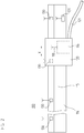
- FIG. 2 It shows a scale 114 with a code track 115, as well as a scanning head 120. Furthermore, a connecting cable 121 is indicated, via which the position measuring device 100 can be connected to a control unit 20.
- the connection cable 121 comprises, for example, the data transmission channel 25 for the data transmission between the first interface unit 11 and the control interface 21, as well as supply lines which supply the scanning head 120 with an operating voltage.
- the second interface unit 116 with the main antenna 118 is shown in the scanning head 120.
- the illustration of the remaining components has been omitted.
- the scale 114 is mounted on a first machine part and the scanning head 120 on a second machine part.
- the scanning head 120 In a relative movement of the first machine part relative to the second machine part in a measuring direction X, the scanning head 120 (and thus the scanning unit 13, not shown) moves along the code track 115 of the scale 114.
- the on this Way generated position signals are, as in the comments too FIG. 1 already described, processed.
- peripheral units 130 in the form of temperature sensors are arranged at regular intervals. Due to the wireless communication between the temperature sensors and the second interface unit 116, it is now very comfortably possible to determine the temperature distribution along the scale 114 and, if necessary, to include the correction of the position values. This can be done both in the control unit 20 and already in the scanning head 120, for example in the position detection unit 12, to which the temperature values are supplied from the communication unit 17 via the data connection 19. The latter is particularly advantageous since there is no need to transmit temperature values to the control unit 20 in addition to the position values.
- peripheral units 130 in this embodiment passive sensors, since in this case can be completely dispensed with an external wiring of the peripheral units 130.
- each peripheral unit 130 would need to have at least two leads coupled to it, either separately or in the form of a bus connection, to the scanhead 120, or directly to the controller 20.
- the peripheral units 130 can of course be attached to any machine parts, or even on a workpiece to be machined to detect temperature fluctuations and correct if necessary.
- this embodiment is not limited to temperature sensors, other types of sensors may be used, such as vibration sensors for detecting impermissible vibrations on the machine, such as caused by a "rattling" of a milling head or a defective bearing.
- the range of the communication can be chosen so large that all peripheral units 130 can be reached at each position of the scanning head 120.
- the data memory may contain information concerning the position-measuring device 100 itself, but also the machine on which the position-measuring device 100 is operated.
- the data memory 131 may contain correction data which describe the measuring standard 114 and in particular the code track 115 and which the position detection unit 12 needs in order to optimally correct position values. This is particularly useful in so-called open length measuring devices, since in these the cultivation of the scale to the machine and the assembly and adjustment of the scanning head 120 relative to the code track 115 usually takes place only at the customer.
- a data memory 131 which is wirelessly, both in terms of data transmission, as well as in terms of the power supply, readable via the radio interface, the adjustment of the scanning head 120 to the measuring scale 114 can be automated and is thus customer friendly and safe ,
- the data memory 131 may be implemented as a read only memory (ROM) or as a random access memory (e.g., EEPROM, flash memory, FRAM, ). In the latter case, information relating to the operation of the position-measuring device 10 can be stored in the data memory 131, for example a serial number of the scanning head 120, the date of the start-up, or the number of operating hours.
- ROM read only memory
- RAM random access memory
- the data memory 131 it may be useful to limit the range of the second interface unit 116, since the content of the Data storage yes directly affects the position measuring device 100. This prevents that when two similar position measuring devices 100 are mounted with data memory 131 in close proximity to each other, the wrong data memory 131 for the adjustment between scale 114 and scanning head 120 is inadvertently used. It is particularly advantageous here to arrange the main antenna 118 of the second interface unit 116 on the scale 114 facing side of the scanning head 120.
- the data memory 131 is an RFID transponder and the second interface unit 116 is an RFID reader or read / write device, the system being dimensioned as a so-called close-coupling system with a few centimeters range.
- NFC Near Field Communication
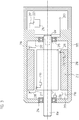
- FIG. 3 shows a position measuring device according to the invention in the form of a drive encoder 200.
- the drive encoder 200 is attached to an electric motor 205.
- the electric motor 205 comprises a rotor 211 with a rotor shaft RW, and stator windings 212.
- the rotor shaft RW is rotatably mounted at two locations by means of radial bearings 214, 215 about its axis of rotation.
- the radial bearings 214, 215 rolling bearings, in particular ball bearings.
- the rotor shaft RW of the rotor 211 of the electric motor 205 is rotatably connected to a transmitter shaft GW of the drive encoder 200.
- the housing of the drive transmitter 200 is fixed to the motor housing 210 of the electric motor 205, so that with the drive encoder 200 of the rotation angle, or the number of complete revolutions of the rotor shaft RW relative to the motor housing 210 is measured.
- the operating principle of the drive encoder 200 is based on the scanning of a code track, which is arranged radially on a circular disc, which represents the measuring graduation, wherein the center of the disc is in turn rotatably connected to the axis of rotation of the encoder shaft GW. This principle is well known to the skilled person and will not be further elaborated here.
- the construction of the drive transmitter 200 corresponds to that of the position-measuring device 10 FIG. 1 , On the representation of components necessary for the description of the embodiment in FIG. 3 are not relevant (measuring scale 14, first interface unit 11, position detection unit 12, scanning unit 13 and communication unit 17) was waived again. According to the invention, only the second interface unit 216 is shown.
- a plurality of peripheral units 230 are arranged, which serve to monitor the state of the electric motor 205.
- the peripheral units 230 on the thrust bearings 214, 215 are vibration sensors, the motor housing 210, the rotor 211, and the stator windings 212 around temperature sensors.
- shielding material eg the motor housing 210
- the motor interior 213 shielding material eg the motor housing 210
- the motor interior 2113 For the installation of the antenna cable 217, suitable recesses are provided in the motor interior 213, for example.
- the connection is made via a plug connector 220.
Landscapes
- Physics & Mathematics (AREA)
- General Physics & Mathematics (AREA)
- Engineering & Computer Science (AREA)
- Computer Networks & Wireless Communication (AREA)
- Arrangements For Transmission Of Measured Signals (AREA)
- Transmission And Conversion Of Sensor Element Output (AREA)
Applications Claiming Priority (2)
| Application Number | Priority Date | Filing Date | Title |
|---|---|---|---|
| DE102011006424A DE102011006424A1 (de) | 2011-03-30 | 2011-03-30 | Positionsmesseinrichtung |
| PCT/EP2012/050783 WO2012130490A1 (de) | 2011-03-30 | 2012-01-19 | Positionsmesseinrichtung |
Publications (2)
| Publication Number | Publication Date |
|---|---|
| EP2691745A1 EP2691745A1 (de) | 2014-02-05 |
| EP2691745B1 true EP2691745B1 (de) | 2018-04-04 |
Family
ID=45833322
Family Applications (1)
| Application Number | Title | Priority Date | Filing Date |
|---|---|---|---|
| EP12708712.0A Active EP2691745B1 (de) | 2011-03-30 | 2012-01-19 | Positionsmesseinrichtung |
Country Status (7)
Families Citing this family (5)
| Publication number | Priority date | Publication date | Assignee | Title |
|---|---|---|---|---|
| DE102012218890A1 (de) | 2012-10-17 | 2014-04-17 | Dr. Johannes Heidenhain Gmbh | Absolutes Positionsmessgerät |
| US9702783B2 (en) * | 2014-08-01 | 2017-07-11 | Rosemount Aerospace Inc. | Air data probe with fluid intrusion sensor |
| DE102016102135B3 (de) * | 2016-02-08 | 2017-08-03 | Asm Assembly Systems Gmbh & Co. Kg | Leiterplatten - Transportsystem und Fertigungssystem |
| DE102016224012A1 (de) * | 2016-12-02 | 2018-06-07 | Dr. Johannes Heidenhain Gmbh | Positionsmesseinrichtung und Verfahren zum Betreiben einer Positionsmesseinrichtung |
| CN110970731A (zh) * | 2018-09-30 | 2020-04-07 | 华为技术有限公司 | 调节装置、天线及通信设备 |
Citations (1)
| Publication number | Priority date | Publication date | Assignee | Title |
|---|---|---|---|---|
| US20060001315A1 (en) * | 2004-01-23 | 2006-01-05 | Stevens James C | Apparatus and method for shifting the center of gravity in a vehicle |
Family Cites Families (31)
| Publication number | Priority date | Publication date | Assignee | Title |
|---|---|---|---|---|
| US5557154A (en) * | 1991-10-11 | 1996-09-17 | Exlar Corporation | Linear actuator with feedback position sensor device |
| US5565864A (en) * | 1993-09-02 | 1996-10-15 | Nikon Corporation | Absolute encoder |
| JPH07249189A (ja) * | 1994-03-09 | 1995-09-26 | Thermo Tekunika:Kk | ストレイン用無線遠隔測定装置 |
| US5574445A (en) * | 1994-12-08 | 1996-11-12 | Bose Corporation | Digital absolute position encoders |
| JP3940970B2 (ja) * | 1997-09-12 | 2007-07-04 | 株式会社東京測器研究所 | ひずみ測定モジュール |
| US6278363B1 (en) * | 2000-07-14 | 2001-08-21 | Motorola, Inc | Method and system for monitoring air pressure of tires on a vehicle |
| JP2003058976A (ja) * | 2001-06-04 | 2003-02-28 | Nsk Ltd | ワイヤレスセンサ、転がり軸受装置、管理装置、及び監視装置 |
| JP4166488B2 (ja) * | 2002-03-05 | 2008-10-15 | ソニーマニュファクチュアリングシステムズ株式会社 | 位置検出装置 |
| JP2003307228A (ja) * | 2002-04-12 | 2003-10-31 | Nsk Ltd | センサ付軸受装置 |
| ES2272965T3 (es) * | 2002-04-15 | 2007-05-01 | Epos Technologies Limited | Metodo y sistema para obtener datos de posicion. |
| JP2004198262A (ja) * | 2002-12-18 | 2004-07-15 | Tamagawa Seiki Co Ltd | 温度センサー付エンコーダの温度設定方法 |
| US7924767B2 (en) * | 2002-12-26 | 2011-04-12 | Sierra Wireless, Inc. | Control and status protocol |
| DE10306231A1 (de) | 2003-02-14 | 2004-08-26 | Dr. Johannes Heidenhain Gmbh | Elektronische Zwischenbaugruppe |
| JP4329478B2 (ja) * | 2003-10-06 | 2009-09-09 | 株式会社日立製作所 | 力学量測定装置 |
| DE102004045849B4 (de) * | 2004-09-20 | 2014-06-05 | Anton Rodi | Messgeber mit Absolut-Signalverarbeitung und Inkremental-Signalausgabe |
| CN200941246Y (zh) * | 2006-04-18 | 2007-08-29 | 武汉利德测控技术股份有限公司 | 格雷母线位移检测系统 |
| US7496481B2 (en) * | 2006-05-19 | 2009-02-24 | Watlow Electric Manufacturing Company | Sensor adaptors and methods |
| DE102006041056C5 (de) | 2006-09-01 | 2015-02-19 | Siemens Aktiengesellschaft | Drehgeber zum Anschluss weiterer Sensoren sowie elektrische Maschine mit einem derartigen Drehgeber |
| WO2009003186A1 (en) * | 2007-06-27 | 2008-12-31 | Brooks Automation, Inc. | Multiple dimension position sensor |
| WO2009055285A2 (en) * | 2007-10-22 | 2009-04-30 | The Timken Company | Absolute position magnetic encoder with binary and decimal output |
| CN101878123B (zh) * | 2007-11-30 | 2013-05-01 | 沃尔沃拉斯特瓦格纳公司 | 识别车轮模块位置的方法 |
| US8744692B2 (en) * | 2007-11-30 | 2014-06-03 | Volvo Lastvagnar Ab | Method of identifying positions of wheel modules |
| WO2009070064A1 (en) * | 2007-11-30 | 2009-06-04 | Volvo Lastvagnar Ab | Method of identifying positions of wheel modules |
| WO2009154748A2 (en) * | 2008-06-17 | 2009-12-23 | Rosemount Inc. | Rf adapter for field device with low voltage intrinsic safety clamping |
| DE102008036554A1 (de) * | 2008-08-06 | 2010-02-11 | Endress + Hauser Process Solutions Ag | Autarkes Feldgerät oder autarker Funkadapter für ein Feldgerät der Automatisierungstechnik |
| WO2010016025A1 (en) * | 2008-08-06 | 2010-02-11 | E-Vitae Pte. Ltd. | Universal body sensor network |
| US8246441B2 (en) * | 2008-10-22 | 2012-08-21 | Wms Gaming Inc. | Gaming machine having position sensor for mechanical reel modularity |
| CN101419078B (zh) * | 2008-12-01 | 2012-02-15 | 深圳职业技术学院 | 运动位移无线检测系统及其运行方法 |
| CN201364112Y (zh) * | 2008-12-25 | 2009-12-16 | 清远市科佳测控科技有限公司 | 一种机械量具指示表 |
| CN201387383Y (zh) * | 2009-04-30 | 2010-01-20 | 武汉铁路科学技术研究发展有限公司 | 机车、车辆数显检测样板 |
| CN101807331B (zh) * | 2010-03-25 | 2012-11-14 | 深圳绿拓科技有限公司 | 一种无源无线传感装置 |
-
2011
- 2011-03-30 DE DE102011006424A patent/DE102011006424A1/de not_active Withdrawn
-
2012
- 2012-01-19 JP JP2014501489A patent/JP6045564B2/ja active Active
- 2012-01-19 US US14/007,432 patent/US9151598B2/en active Active
- 2012-01-19 EP EP12708712.0A patent/EP2691745B1/de active Active
- 2012-01-19 ES ES12708712.0T patent/ES2671725T3/es active Active
- 2012-01-19 CN CN201280013841.5A patent/CN103429995B/zh active Active
- 2012-01-19 WO PCT/EP2012/050783 patent/WO2012130490A1/de active Application Filing
Patent Citations (1)
| Publication number | Priority date | Publication date | Assignee | Title |
|---|---|---|---|---|
| US20060001315A1 (en) * | 2004-01-23 | 2006-01-05 | Stevens James C | Apparatus and method for shifting the center of gravity in a vehicle |
Also Published As
| Publication number | Publication date |
|---|---|
| ES2671725T3 (es) | 2018-06-08 |
| WO2012130490A1 (de) | 2012-10-04 |
| CN103429995A (zh) | 2013-12-04 |
| US9151598B2 (en) | 2015-10-06 |
| CN103429995B (zh) | 2016-12-14 |
| JP6045564B2 (ja) | 2016-12-14 |
| US20140022561A1 (en) | 2014-01-23 |
| JP2014513282A (ja) | 2014-05-29 |
| DE102011006424A1 (de) | 2012-10-04 |
| EP2691745A1 (de) | 2014-02-05 |
Similar Documents
| Publication | Publication Date | Title |
|---|---|---|
| EP2691745B1 (de) | Positionsmesseinrichtung | |
| EP2113742B2 (de) | Messvorrichtung mit Zwei-Kanal-Abtastung | |
| DE102014100301B3 (de) | Optoelektronischer Sensor zur Erfassung von Objekten in einem Überwachungsbereich | |
| EP1923670A1 (de) | Positionsmesseinrichtung | |
| WO2012004020A1 (de) | Vorrichtung zur optischen messung der biegung eines rotorblatts einer windkraftanlage | |
| DE102017216666A1 (de) | Positionsmesseinrichtung und Verfahren zum Betreiben einer Positionsmesseinrichtung | |
| EP3721175B1 (de) | Sensorsystem zur bestimmung mindestens einer rotationseigenschaft eines um mindestens eine rotationsachse rotierenden elements | |
| DE102017115625A1 (de) | Motor mit einer Funktion zum Erzeugen und Einspeisen von elektrischer Energie an einem Spulenendabschnitt | |
| DE102008053105A1 (de) | Vorrichtung und Verfahren zur Datenübertragung zwischen einem Positionsmessgerät und einer Folgeelektronik | |
| EP3964903B1 (de) | Vorrichtung und verfahren zur verarbeitung von rotationsabhängigen messwerten | |
| DE102014116861B4 (de) | Werkzeug umfassend eine Vorrichtung zum Erfassen von Indikatoren für eine vorbeugende Instandhaltung und ein System umfassend das Werkzeug | |
| DE102004011457A1 (de) | Aktor und Verfahren zum Betreiben eines Aktors | |
| EP1949039B1 (de) | Positionsmesssystem | |
| DE10135960B4 (de) | Absolutpositions-Detektionsvorrichtung für einen Linearbetätiger | |
| DE102012103245A1 (de) | Vereinfachte Inbetriebnahme von Antrieben mit individuellen Motordaten | |
| US20080144168A1 (en) | Microscope Having A Sensor Operating In Non-Contact Fashion | |
| EP1750101B1 (de) | Feldmodulierende Winkelmesseinrichtung und Verfahren zu deren Betrieb | |
| DE10251829B4 (de) | Meßeinrichtung für thermische Drift | |
| EP1126248B1 (de) | Positionsmesseinrichtung und Verfahren zu deren Betrieb | |
| DE112010000429T5 (de) | Informationsmanagementsystem für eine Antriebsvorrichtung und Verfahren zur Herstellungder Antriebsvorrichtung | |
| EP3760980A1 (de) | Winkelmesseinrichtung | |
| EP2469239A1 (de) | Multiturn-Winkelmessvorrichtung | |
| DE102017205267A1 (de) | Positionsmesseinrichtung und Verfahren zum Betreiben einer Positionsmesseinrichtung | |
| WO1990003553A1 (de) | Verfahren und vorrichtung zur absoluten positionsbestimmung an einer drehachse | |
| EP3760979B1 (de) | Positionsmesseinrichtung und verfahren zum betreiben einer positionsmesseinrichtung |
Legal Events
| Date | Code | Title | Description |
|---|---|---|---|
| PUAI | Public reference made under article 153(3) epc to a published international application that has entered the european phase |
Free format text: ORIGINAL CODE: 0009012 |
|
| 17P | Request for examination filed |
Effective date: 20131030 |
|
| AK | Designated contracting states |
Kind code of ref document: A1 Designated state(s): AL AT BE BG CH CY CZ DE DK EE ES FI FR GB GR HR HU IE IS IT LI LT LU LV MC MK MT NL NO PL PT RO RS SE SI SK SM TR |
|
| DAX | Request for extension of the european patent (deleted) | ||
| 17Q | First examination report despatched |
Effective date: 20140808 |
|
| STAA | Information on the status of an ep patent application or granted ep patent |
Free format text: STATUS: EXAMINATION IS IN PROGRESS |
|
| REG | Reference to a national code |
Ref country code: DE Ref legal event code: R079 Ref document number: 502012012482 Country of ref document: DE Free format text: PREVIOUS MAIN CLASS: G01D0021020000 Ipc: G01D0021000000 |
|
| GRAP | Despatch of communication of intention to grant a patent |
Free format text: ORIGINAL CODE: EPIDOSNIGR1 |
|
| STAA | Information on the status of an ep patent application or granted ep patent |
Free format text: STATUS: GRANT OF PATENT IS INTENDED |
|
| RIC1 | Information provided on ipc code assigned before grant |
Ipc: G01D 21/00 20060101AFI20171123BHEP |
|
| INTG | Intention to grant announced |
Effective date: 20171221 |
|
| GRAS | Grant fee paid |
Free format text: ORIGINAL CODE: EPIDOSNIGR3 |
|
| GRAA | (expected) grant |
Free format text: ORIGINAL CODE: 0009210 |
|
| STAA | Information on the status of an ep patent application or granted ep patent |
Free format text: STATUS: THE PATENT HAS BEEN GRANTED |
|
| AK | Designated contracting states |
Kind code of ref document: B1 Designated state(s): AL AT BE BG CH CY CZ DE DK EE ES FI FR GB GR HR HU IE IS IT LI LT LU LV MC MK MT NL NO PL PT RO RS SE SI SK SM TR |
|
| REG | Reference to a national code |
Ref country code: GB Ref legal event code: FG4D Free format text: NOT ENGLISH |
|
| REG | Reference to a national code |
Ref country code: CH Ref legal event code: EP Ref country code: CH Ref legal event code: NV Representative=s name: ICB INGENIEURS CONSEILS EN BREVETS SA, CH |
|
| REG | Reference to a national code |
Ref country code: AT Ref legal event code: REF Ref document number: 986078 Country of ref document: AT Kind code of ref document: T Effective date: 20180415 |
|
| REG | Reference to a national code |
Ref country code: DE Ref legal event code: R096 Ref document number: 502012012482 Country of ref document: DE |
|
| REG | Reference to a national code |
Ref country code: IE Ref legal event code: FG4D Free format text: LANGUAGE OF EP DOCUMENT: GERMAN |
|
| REG | Reference to a national code |
Ref country code: ES Ref legal event code: FG2A Ref document number: 2671725 Country of ref document: ES Kind code of ref document: T3 Effective date: 20180608 |
|
| REG | Reference to a national code |
Ref country code: NL Ref legal event code: MP Effective date: 20180404 |
|
| REG | Reference to a national code |
Ref country code: LT Ref legal event code: MG4D |
|
| PG25 | Lapsed in a contracting state [announced via postgrant information from national office to epo] |
Ref country code: NL Free format text: LAPSE BECAUSE OF FAILURE TO SUBMIT A TRANSLATION OF THE DESCRIPTION OR TO PAY THE FEE WITHIN THE PRESCRIBED TIME-LIMIT Effective date: 20180404 |
|
| PG25 | Lapsed in a contracting state [announced via postgrant information from national office to epo] |
Ref country code: SE Free format text: LAPSE BECAUSE OF FAILURE TO SUBMIT A TRANSLATION OF THE DESCRIPTION OR TO PAY THE FEE WITHIN THE PRESCRIBED TIME-LIMIT Effective date: 20180404 Ref country code: AL Free format text: LAPSE BECAUSE OF FAILURE TO SUBMIT A TRANSLATION OF THE DESCRIPTION OR TO PAY THE FEE WITHIN THE PRESCRIBED TIME-LIMIT Effective date: 20180404 Ref country code: FI Free format text: LAPSE BECAUSE OF FAILURE TO SUBMIT A TRANSLATION OF THE DESCRIPTION OR TO PAY THE FEE WITHIN THE PRESCRIBED TIME-LIMIT Effective date: 20180404 Ref country code: BG Free format text: LAPSE BECAUSE OF FAILURE TO SUBMIT A TRANSLATION OF THE DESCRIPTION OR TO PAY THE FEE WITHIN THE PRESCRIBED TIME-LIMIT Effective date: 20180704 Ref country code: NO Free format text: LAPSE BECAUSE OF FAILURE TO SUBMIT A TRANSLATION OF THE DESCRIPTION OR TO PAY THE FEE WITHIN THE PRESCRIBED TIME-LIMIT Effective date: 20180704 Ref country code: LT Free format text: LAPSE BECAUSE OF FAILURE TO SUBMIT A TRANSLATION OF THE DESCRIPTION OR TO PAY THE FEE WITHIN THE PRESCRIBED TIME-LIMIT Effective date: 20180404 Ref country code: PL Free format text: LAPSE BECAUSE OF FAILURE TO SUBMIT A TRANSLATION OF THE DESCRIPTION OR TO PAY THE FEE WITHIN THE PRESCRIBED TIME-LIMIT Effective date: 20180404 |
|
| PG25 | Lapsed in a contracting state [announced via postgrant information from national office to epo] |
Ref country code: GR Free format text: LAPSE BECAUSE OF FAILURE TO SUBMIT A TRANSLATION OF THE DESCRIPTION OR TO PAY THE FEE WITHIN THE PRESCRIBED TIME-LIMIT Effective date: 20180705 Ref country code: HR Free format text: LAPSE BECAUSE OF FAILURE TO SUBMIT A TRANSLATION OF THE DESCRIPTION OR TO PAY THE FEE WITHIN THE PRESCRIBED TIME-LIMIT Effective date: 20180404 Ref country code: RS Free format text: LAPSE BECAUSE OF FAILURE TO SUBMIT A TRANSLATION OF THE DESCRIPTION OR TO PAY THE FEE WITHIN THE PRESCRIBED TIME-LIMIT Effective date: 20180404 Ref country code: LV Free format text: LAPSE BECAUSE OF FAILURE TO SUBMIT A TRANSLATION OF THE DESCRIPTION OR TO PAY THE FEE WITHIN THE PRESCRIBED TIME-LIMIT Effective date: 20180404 |
|
| PG25 | Lapsed in a contracting state [announced via postgrant information from national office to epo] |
Ref country code: PT Free format text: LAPSE BECAUSE OF FAILURE TO SUBMIT A TRANSLATION OF THE DESCRIPTION OR TO PAY THE FEE WITHIN THE PRESCRIBED TIME-LIMIT Effective date: 20180806 |
|
| REG | Reference to a national code |
Ref country code: DE Ref legal event code: R097 Ref document number: 502012012482 Country of ref document: DE |
|
| PG25 | Lapsed in a contracting state [announced via postgrant information from national office to epo] |
Ref country code: RO Free format text: LAPSE BECAUSE OF FAILURE TO SUBMIT A TRANSLATION OF THE DESCRIPTION OR TO PAY THE FEE WITHIN THE PRESCRIBED TIME-LIMIT Effective date: 20180404 Ref country code: EE Free format text: LAPSE BECAUSE OF FAILURE TO SUBMIT A TRANSLATION OF THE DESCRIPTION OR TO PAY THE FEE WITHIN THE PRESCRIBED TIME-LIMIT Effective date: 20180404 Ref country code: DK Free format text: LAPSE BECAUSE OF FAILURE TO SUBMIT A TRANSLATION OF THE DESCRIPTION OR TO PAY THE FEE WITHIN THE PRESCRIBED TIME-LIMIT Effective date: 20180404 Ref country code: SK Free format text: LAPSE BECAUSE OF FAILURE TO SUBMIT A TRANSLATION OF THE DESCRIPTION OR TO PAY THE FEE WITHIN THE PRESCRIBED TIME-LIMIT Effective date: 20180404 |
|
| PLBE | No opposition filed within time limit |
Free format text: ORIGINAL CODE: 0009261 |
|
| STAA | Information on the status of an ep patent application or granted ep patent |
Free format text: STATUS: NO OPPOSITION FILED WITHIN TIME LIMIT |
|
| PG25 | Lapsed in a contracting state [announced via postgrant information from national office to epo] |
Ref country code: SM Free format text: LAPSE BECAUSE OF FAILURE TO SUBMIT A TRANSLATION OF THE DESCRIPTION OR TO PAY THE FEE WITHIN THE PRESCRIBED TIME-LIMIT Effective date: 20180404 |
|
| 26N | No opposition filed |
Effective date: 20190107 |
|
| PG25 | Lapsed in a contracting state [announced via postgrant information from national office to epo] |
Ref country code: SI Free format text: LAPSE BECAUSE OF FAILURE TO SUBMIT A TRANSLATION OF THE DESCRIPTION OR TO PAY THE FEE WITHIN THE PRESCRIBED TIME-LIMIT Effective date: 20180404 |
|
| PG25 | Lapsed in a contracting state [announced via postgrant information from national office to epo] |
Ref country code: MC Free format text: LAPSE BECAUSE OF FAILURE TO SUBMIT A TRANSLATION OF THE DESCRIPTION OR TO PAY THE FEE WITHIN THE PRESCRIBED TIME-LIMIT Effective date: 20180404 |
|
| PG25 | Lapsed in a contracting state [announced via postgrant information from national office to epo] |
Ref country code: LU Free format text: LAPSE BECAUSE OF NON-PAYMENT OF DUE FEES Effective date: 20190119 |
|
| REG | Reference to a national code |
Ref country code: BE Ref legal event code: MM Effective date: 20190131 |
|
| REG | Reference to a national code |
Ref country code: IE Ref legal event code: MM4A |
|
| PG25 | Lapsed in a contracting state [announced via postgrant information from national office to epo] |
Ref country code: FR Free format text: LAPSE BECAUSE OF NON-PAYMENT OF DUE FEES Effective date: 20190131 |
|
| PG25 | Lapsed in a contracting state [announced via postgrant information from national office to epo] |
Ref country code: BE Free format text: LAPSE BECAUSE OF NON-PAYMENT OF DUE FEES Effective date: 20190131 |
|
| PG25 | Lapsed in a contracting state [announced via postgrant information from national office to epo] |
Ref country code: IE Free format text: LAPSE BECAUSE OF NON-PAYMENT OF DUE FEES Effective date: 20190119 |
|
| REG | Reference to a national code |
Ref country code: AT Ref legal event code: MM01 Ref document number: 986078 Country of ref document: AT Kind code of ref document: T Effective date: 20190119 |
|
| PG25 | Lapsed in a contracting state [announced via postgrant information from national office to epo] |
Ref country code: TR Free format text: LAPSE BECAUSE OF FAILURE TO SUBMIT A TRANSLATION OF THE DESCRIPTION OR TO PAY THE FEE WITHIN THE PRESCRIBED TIME-LIMIT Effective date: 20180404 |
|
| PG25 | Lapsed in a contracting state [announced via postgrant information from national office to epo] |
Ref country code: AT Free format text: LAPSE BECAUSE OF NON-PAYMENT OF DUE FEES Effective date: 20190119 |
|
| PG25 | Lapsed in a contracting state [announced via postgrant information from national office to epo] |
Ref country code: MT Free format text: LAPSE BECAUSE OF FAILURE TO SUBMIT A TRANSLATION OF THE DESCRIPTION OR TO PAY THE FEE WITHIN THE PRESCRIBED TIME-LIMIT Effective date: 20180404 |
|
| PG25 | Lapsed in a contracting state [announced via postgrant information from national office to epo] |
Ref country code: CY Free format text: LAPSE BECAUSE OF FAILURE TO SUBMIT A TRANSLATION OF THE DESCRIPTION OR TO PAY THE FEE WITHIN THE PRESCRIBED TIME-LIMIT Effective date: 20180404 |
|
| PG25 | Lapsed in a contracting state [announced via postgrant information from national office to epo] |
Ref country code: IS Free format text: LAPSE BECAUSE OF FAILURE TO SUBMIT A TRANSLATION OF THE DESCRIPTION OR TO PAY THE FEE WITHIN THE PRESCRIBED TIME-LIMIT Effective date: 20180804 |
|
| PG25 | Lapsed in a contracting state [announced via postgrant information from national office to epo] |
Ref country code: HU Free format text: LAPSE BECAUSE OF FAILURE TO SUBMIT A TRANSLATION OF THE DESCRIPTION OR TO PAY THE FEE WITHIN THE PRESCRIBED TIME-LIMIT; INVALID AB INITIO Effective date: 20120119 |
|
| PG25 | Lapsed in a contracting state [announced via postgrant information from national office to epo] |
Ref country code: MK Free format text: LAPSE BECAUSE OF FAILURE TO SUBMIT A TRANSLATION OF THE DESCRIPTION OR TO PAY THE FEE WITHIN THE PRESCRIBED TIME-LIMIT Effective date: 20180404 |
|
| PGFP | Annual fee paid to national office [announced via postgrant information from national office to epo] |
Ref country code: DE Payment date: 20250121 Year of fee payment: 14 |
|
| PGFP | Annual fee paid to national office [announced via postgrant information from national office to epo] |
Ref country code: ES Payment date: 20250226 Year of fee payment: 14 |
|
| PGFP | Annual fee paid to national office [announced via postgrant information from national office to epo] |
Ref country code: CH Payment date: 20250201 Year of fee payment: 14 |
|
| PGFP | Annual fee paid to national office [announced via postgrant information from national office to epo] |
Ref country code: CZ Payment date: 20250110 Year of fee payment: 14 |
|
| PGFP | Annual fee paid to national office [announced via postgrant information from national office to epo] |
Ref country code: GB Payment date: 20250128 Year of fee payment: 14 Ref country code: IT Payment date: 20250129 Year of fee payment: 14 |