EP2691015B1 - Überwachungssystem - Google Patents
Überwachungssystem Download PDFInfo
- Publication number
- EP2691015B1 EP2691015B1 EP12725297.1A EP12725297A EP2691015B1 EP 2691015 B1 EP2691015 B1 EP 2691015B1 EP 12725297 A EP12725297 A EP 12725297A EP 2691015 B1 EP2691015 B1 EP 2691015B1
- Authority
- EP
- European Patent Office
- Prior art keywords
- coil
- monitoring
- party device
- monitored
- party
- Prior art date
- Legal status (The legal status is an assumption and is not a legal conclusion. Google has not performed a legal analysis and makes no representation as to the accuracy of the status listed.)
- Active
Links
Images
Classifications
-
- A—HUMAN NECESSITIES
- A61—MEDICAL OR VETERINARY SCIENCE; HYGIENE
- A61N—ELECTROTHERAPY; MAGNETOTHERAPY; RADIATION THERAPY; ULTRASOUND THERAPY
- A61N1/00—Electrotherapy; Circuits therefor
- A61N1/18—Applying electric currents by contact electrodes
- A61N1/32—Applying electric currents by contact electrodes alternating or intermittent currents
- A61N1/38—Applying electric currents by contact electrodes alternating or intermittent currents for producing shock effects
- A61N1/39—Heart defibrillators
- A61N1/3925—Monitoring; Protecting
-
- A—HUMAN NECESSITIES
- A61—MEDICAL OR VETERINARY SCIENCE; HYGIENE
- A61B—DIAGNOSIS; SURGERY; IDENTIFICATION
- A61B5/00—Measuring for diagnostic purposes; Identification of persons
- A61B5/0002—Remote monitoring of patients using telemetry, e.g. transmission of vital signals via a communication network
- A61B5/0015—Remote monitoring of patients using telemetry, e.g. transmission of vital signals via a communication network characterised by features of the telemetry system
-
- G—PHYSICS
- G08—SIGNALLING
- G08C—TRANSMISSION SYSTEMS FOR MEASURED VALUES, CONTROL OR SIMILAR SIGNALS
- G08C17/00—Arrangements for transmitting signals characterised by the use of a wireless electrical link
- G08C17/02—Arrangements for transmitting signals characterised by the use of a wireless electrical link using a radio link
-
- A—HUMAN NECESSITIES
- A61—MEDICAL OR VETERINARY SCIENCE; HYGIENE
- A61B—DIAGNOSIS; SURGERY; IDENTIFICATION
- A61B2560/00—Constructional details of operational features of apparatus; Accessories for medical measuring apparatus
- A61B2560/02—Operational features
- A61B2560/0266—Operational features for monitoring or limiting apparatus function
- A61B2560/0271—Operational features for monitoring or limiting apparatus function using a remote monitoring unit
-
- A—HUMAN NECESSITIES
- A61—MEDICAL OR VETERINARY SCIENCE; HYGIENE
- A61M—DEVICES FOR INTRODUCING MEDIA INTO, OR ONTO, THE BODY; DEVICES FOR TRANSDUCING BODY MEDIA OR FOR TAKING MEDIA FROM THE BODY; DEVICES FOR PRODUCING OR ENDING SLEEP OR STUPOR
- A61M2205/00—General characteristics of the apparatus
- A61M2205/35—Communication
- A61M2205/3507—Communication with implanted devices, e.g. external control
- A61M2205/3523—Communication with implanted devices, e.g. external control using telemetric means
-
- A—HUMAN NECESSITIES
- A61—MEDICAL OR VETERINARY SCIENCE; HYGIENE
- A61N—ELECTROTHERAPY; MAGNETOTHERAPY; RADIATION THERAPY; ULTRASOUND THERAPY
- A61N1/00—Electrotherapy; Circuits therefor
- A61N1/18—Applying electric currents by contact electrodes
- A61N1/32—Applying electric currents by contact electrodes alternating or intermittent currents
- A61N1/36—Applying electric currents by contact electrodes alternating or intermittent currents for stimulation
- A61N1/372—Arrangements in connection with the implantation of stimulators
- A61N1/37211—Means for communicating with stimulators
- A61N1/37252—Details of algorithms or data aspects of communication system, e.g. handshaking, transmitting specific data or segmenting data
- A61N1/37276—Details of algorithms or data aspects of communication system, e.g. handshaking, transmitting specific data or segmenting data characterised by means for reducing power consumption during telemetry
-
- H—ELECTRICITY
- H04—ELECTRIC COMMUNICATION TECHNIQUE
- H04B—TRANSMISSION
- H04B5/00—Near-field transmission systems, e.g. inductive or capacitive transmission systems
- H04B5/20—Near-field transmission systems, e.g. inductive or capacitive transmission systems characterised by the transmission technique; characterised by the transmission medium
- H04B5/24—Inductive coupling
- H04B5/26—Inductive coupling using coils
Definitions
- the invention relates to a monitoring system for monitoring a third-party device, in particular a medical device, comprising a monitoring device (2) and the third-party device to be monitored, wherein the third-party device has a signaling device for displaying the device status and / or relevant device properties and the monitoring device is assigned to the third-party device, without this being connected to an intervention in the housing of the third party device and / or the functionality of the third party device.
- an implantable medical device which is capable of communicating error messages via a charging coil, in particular when the conventional telemetry nationalities have failed.
- a typical application example of the previously known solution is an implantable cardiac pacemaker, which is associated with an external controller for monitoring the functionality of the cardiac pacemaker.
- data can be exchanged by the coupled coils of the controller and the pacemaker in the event that these are error messages, they are first transmitted to a built-in pacemaker microcontroller and then inductively via a modulation unit on the mentioned coil according to Transmit modulation to the inductively connected external controller.
- Another monitoring system for detecting and transmitting status information of a portable medical device is from the European patent EP 1435076 B1 previously known.
- a device is to be developed according to the previously known solution, with which the displayed status information can be detected and optionally transmitted to a remote monitoring device.
- the prior art solution therefore proposes to associate with the medical device a detection device for detecting a change in state of the status indicator of the portable medical device, the receiver for detecting the change of state being coupled to a transmission device enabling a detected change of state of the status indication to a remote receiver.
- condition indicator monitored according to the European patent is an opti-mal Display monitored by an optical detection device. This assumes, first, that an unobstructed optical channel is available between the receiver of the monitoring device and the status display. However, depending on the location and storage of the medical device to be monitored, it is often difficult to associate the monitored medical device with an attachment that has unobstructed eye contact with the status indicator of the monitored device. But even if this is ensured, the optical channel may be disturbed for many reasons - such as by stray or glare - in which case an emergency signal would have to be detected, although the state of the monitored device has not changed.
- a malfunction of the status display also leads to an emergency signal, even if the function of the medical device is otherwise intact.
- the status display is configured so that it displays only a malfunction active, the previously known monitoring device can therefore no longer function when the status display is faulty.
- the invention is based on the object to provide a monitoring device for a third party, but in particular for a medical device, whose function is independent of the function of any status display of the device and which also works then, when the optical channel between a detection device and the monitored device is disturbed.
- the monitoring is not dependent on the function of a possible status display of the device. In other words, it is not a status display, but rather the function of the device itself is monitored.
- This is achieved by contactless monitoring of the relevant current by means of a coil by utilizing the induction effect of the current.
- the coil is arranged in the vicinity of the power supply of the monitored device.
- Another advantage of the inductive monitoring of the device state is that even with installed monitoring device no change or impairment of the user interface of the monitored device is required. For the rest, the monitoring, in addition to the monitoring of the device status, possibly also monitors for possible changes in the device status.
- the coil for detecting a significant current in the vicinity of the battery of the third party device is arranged.
- This arrangement is based on the knowledge that the third-party devices to be monitored, in particular Although medical devices must be constantly functioning and ready for use, they are often not always in operation, but rather in a provision.
- This standby state is usually referred to as a so-called sleep mode or power-saving mode in which only the functions of the device are maintained, which are necessary to maintain the operational readiness of the device in case of emergency.
- the functionality of the device is therefore given when at least the necessary for maintaining the sleep mode current is obtained from the device.
- This power is supplied by either a device external or a device-internal power supply, so for example in the case of a stand-alone solution and network-independent device setup of a built-in third-party battery.
- a device external or a device-internal power supply so for example in the case of a stand-alone solution and network-independent device setup of a built-in third-party battery.
- the coil in the vicinity of the power supply or the battery of the third party device or in the vicinity of other for the purpose of monitoring significant tracks is arranged.
- the monitoring of the third-party device realized with the monitoring system does not have to be restricted to a passively reacting monitoring unit, but can actively call up a device status display by means of an actuator integrated in the monitoring unit, which then again correlates a current flow or a correlating current flow correlating with the display and the device state Changing the current flow of the current monitored by the coil, which is then detected by means of the coil. In this way, an active and thus preventive monitoring of the third party device is realized.
- the coil Due to the inductive effect of the current flow, the coil generates an alternating current or a periodic signal or a pulse signal that is proportional to the detected current. This signal can then be transmitted to an optionally remote evaluation or queried by such an evaluation.
- the detection unit in which the coil is integrated can be provided with a radio transmission module for wireless transmission and / or remote interrogation of the signal detected by means of the coil.
- the monitoring system is used in conjunction with a defibrillator, which is kept in particular in public facilities for emergencies.
- a defibrillator is also functional in an emergency.
- a power monitor with inductive receiver suitable for a non-implantable third-party medical device is off WO9941616 known.
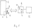
- the block diagram first shows a monitoring system comprising a third-party device to be monitored, here a defibrillator 1, to which a monitoring device 2 with integrated coil 3 is assigned.
- the defibrillator 1 is usually kept in a public building for emergencies and is independent of the rest of the power supply to maintain its functionality, d. H. provided with a battery 4 to maintain the operating condition.
- the monitoring device 2 with the integrated coil 3 is arranged in the vicinity of the battery 4, so that the current flowing in the sleep mode of the defibrillator 1 current to maintain the basic operability of the defibrillator 1 can be detected by means of the coil 3 by way of inductive coupling ,
- the coil 3 Due to the induced AC voltage, the coil 3 generates a periodic signal that is proportional to the monitored current flow within the defibrillator 1.
- This signal or a signal proportional to the signal can then be transmitted wirelessly to a normally remote evaluation unit 6 by means of a radio transmission module 5 likewise integrated in the monitoring device 2.
- the evaluation unit 6 usually contains a processor unit 7 and a memory element 10 for storing the signals transmitted by the monitoring device 2.
- an alarm signal is detected by the evaluation unit 6.
- the alarm signal is usually wireless or wired directly into a central data processing unit 11, such as an emergency call center or a service center, fed.
- the service center will then commission a technician who either exchanges or repairs the monitored third party, which is not the subject of the invention to be discussed herein.
- a monitoring system in particular for monitoring emergency medical devices, is described above, which makes it possible, independently of the status display of the monitored medical device itself, to detect the device state, in particular its operational readiness, and if necessary to transmit it to a remote evaluation unit, so that from a central processing unit from the decentralized distributed medical devices, in particular defibrillators, monitored for their functionality and possibly repaired, maintained or replaced.
Landscapes
- Health & Medical Sciences (AREA)
- Engineering & Computer Science (AREA)
- Life Sciences & Earth Sciences (AREA)
- Computer Networks & Wireless Communication (AREA)
- Physics & Mathematics (AREA)
- Heart & Thoracic Surgery (AREA)
- Biomedical Technology (AREA)
- Animal Behavior & Ethology (AREA)
- General Health & Medical Sciences (AREA)
- Public Health (AREA)
- Veterinary Medicine (AREA)
- General Physics & Mathematics (AREA)
- Biophysics (AREA)
- Pathology (AREA)
- Medical Informatics (AREA)
- Molecular Biology (AREA)
- Surgery (AREA)
- Radiology & Medical Imaging (AREA)
- Nuclear Medicine, Radiotherapy & Molecular Imaging (AREA)
- Cardiology (AREA)
- Electrotherapy Devices (AREA)
- Measuring And Recording Apparatus For Diagnosis (AREA)
Description
- Die Erfindung betrifft ein Überwachungssystem zur Überwachung eines Drittgerätes, insbesondere eines medizinischen Gerätes, umfassend eine Überwachungsvorrichtung (2) und das zu überwachende Drittgerät, wobei das Drittgerät eine Signalvorrichtung zur Anzeige des Gerätezustands und/oder relevanter Geräteeigenschaften aufweist und die Überwachungsvorrichtung dem Drittgerät zugeordnet ist, ohne dass hiermit ein Eingriff in das Gehäuse des Drittgerätes und/oder die Funktionalität des Drittgerätes verbunden ist.
- In diesem Zusammenhang ist aus der
US 2010/179618 A1 eine implantierbare medizinische Vorrichtung vorbekannt, die in der Lage ist, Fehlermeldungen über eine Ladespule zu kommunizieren, insbesondere, wenn die herkömmlichen Telemetrie-Nationalitäten ausgefallen sind. Ein typisches Anwendungsbeispiel für die vorbekannte Lösung ist ein implantierbarer Herzschrittmacher, dem ein externer Controller zur Überwachung der Funktionalität des Herzschrittmachers zugeordnet ist. Hierzu können Daten durch die miteinander gekoppelten Spulen des Controllers und des Herzschrittmachers ausgetauscht werden für den Fall, dass es sich dabei um Fehlermeldungen handelt, werden diese zunächst an einen in den Herzschrittmacher integrierten Microcontroller übermittelt und dann über eine Modulationseinheit über die erwähnte Spule induktiv nach entsprechender Modulation an den induktiv angeschlossenen externen Controller übertragen. - Ein weiteres Überwachungssystem zum Erfassen und Übertragen von Statusinformationen einer tragbaren medizinischen Vorrichtung ist aus dem europäischen Patent
EP 1435076 B1 vorbekannt. - Obwohl medizinische Vorrichtungen zur Überwachung lebenserhaltender Funktionen, auf die im Notfall zugegriffen wird, üblicherweise mit einer Anzeige versehen sind, die die Funktionsfähigkeit des entsprechenden Gerätes signalisiert, sind diese Anzeigen in der Regel im täglichen Gebrauch nicht ausreichend. Wenn beispielsweise eine tragbare medizinische Vorrichtung, wie etwa ein Defibrillator, in einem Schrank, Kasten o. ä. aufbewahrt wird, beispielsweise um den unbefugten Zugriff zu verhindern, so wird eine optische oder akustische Zustandsanzeige in der Regel unbeachtet bleiben.
- Ausgehend von diesem Stand der Technik soll gemäß der vorbekannten Lösung ein Gerät entwickelt werden, mit dem die angezeigten Statusinformationen erfasst und gegebenenfalls an eine entfernte Überwachungsvorrichtung übermittelt werden können. Dabei ist in der Regel bei derartigen Zusatzeinrichtungen zu beachten, dass ein Eingriff in das bereits bestehende, zu überwachende Gerät ohne Verlust der medizinischen Zulassungen in diesem Zusammenhang nicht möglich ist und daher möglichst vermieden werden soll. Die vorbekannte Lösung schlägt daher vor, dem medizinischen Gerät eine Erfassungsvorrichtung zum Detektieren einer Zustandsänderung des Statusanzeigers der tragbaren medizinischen Vorrichtung zuzuordnen, wobei der Empfänger zum Detektieren der Zustandsänderung mit einer Übertragungseinrichtung gekoppelt ist, die eine detektierte Zustandsänderung der Statusanzeige an einen entfernten Empfänger ermöglicht.
- Bei richtigem Verständnis handelt es sich bei der gemäß dem europäischen Patent überwachten Zustandsanzeige um eine optisehe Anzeige, die mit einer optischen Erfassungsvorrichtung überwacht wird. Dies setzt zunächst voraus, dass zwischen dem Empfänger der Überwachungsvorrichtung und der Zustandsanzeige ein ungehinderter optischer Kanal zur Verfügung steht. Je nach Lage und Aufbewahrung der zu überwachenden medizinischen Vorrichtung ist es allerdings in vielen Fällen schwierig, der überwachten medizinischen Vorrichtung ein Zusatzgerät zuzuordnen, das ungehinderten Blickkontakt mit der Zustandsanzeige des überwachten Gerätes hat. Doch selbst wenn dies gewährleistet ist, kann der optische Kanal aus vielen Gründen gestört sein - etwa durch Streu- oder Blendlicht -, wobei in diesem Falle ein Notsignal detektiert werden müsste, obgleich sich an dem Zustand des überwachten Gerätes nichts geändert hat. Im Übrigen führt bei dem aus dem europäischen Patent bekannten System eine Funktionsstörung der Zustandsanzeige ebenfalls zu einem Notsignal, auch dann, wenn die Funktion des medizinischen Gerätes ansonsten intakt ist. Für den Fall, dass bei der vorbekannten Überwachungseinrichtung die Zustandsanzeige so konfiguriert ist, dass sie lediglich eine Betriebsstörung aktiv anzeigt, kann die vorbekannte Überwachungseinrichtung folglich bei defekter Zustandsanzeige nicht mehr funktionieren.
- Ausgehend von diesem Stand der Technik liegt der Erfindung die Aufgabe zu Grunde, eine Überwachungsvorrichtung für ein Drittgerät, insbesondere aber für eine medizinische Vorrichtung, zu schaffen, deren Funktion unabhängig von der Funktion einer etwaigen Zustandsanzeige des Gerätes ist und die im Übrigen auch dann funktioniert, wenn der optische Kanal zwischen einer Erfassungsvorrichtung und dem überwachten Gerät gestört ist.
- Die erfindungsgemäße Aufgabe wird durch ein System mit den Merkmalen des Hauptanspruchs gelöst. Vorteilhafte Ausgestaltungen der Erfindung können den abhängigen Ansprüchen 2 bis 8 entnommen werden.
- Dadurch, dass im Rahmen der erfindungsgemäßen Lösung nicht eine Zustandsanzeige überwacht wird, sondern vielmehr ein im Gerät zur Aufrechterhaltung der gerätetechnischen Funktionen notwendiger Strom, hängt die Überwachung nicht von der Funktion einer möglichen Zustandsanzeige des Gerätes ab. Anders ausgedrückt: es wird nicht eine Zustandsanzeige, sondern vielmehr die Funktion des Gerätes selbst überwacht. Dies gelingt, indem der relevante Strom mittels einer Spule durch Ausnutzung der Induktionswirkung des Stromes kontaktlos überwacht wird. Hierzu ist die Spule in der Nähe der Spannungsversorgung des überwachten Gerätes angeordnet. Nachdem die Überwachungsvorrichtung mittels induktiver Kopplung arbeitet, ist die Funktionsfähigkeit des Überwachungssystems unabhängig von einem direkten oder indirekten Sichtkontakt mit einer Zustandsanzeige.
- Ein weiterer Vorteil der induktiven Überwachung des Gerätezustandes besteht darin, dass auch bei installierter Überwachungsvorrichtung keinerlei Veränderung oder Beeinträchtigung des User-Interfaces des überwachten Gerätes erforderlich ist. Im übrigen leistet die Überwachung neben der Überwachung des Gerätezustandes ggf. auch eine Überwachung auf mögliche Änderungen des Gerätezustandes.
- In vorteilhafter Ausgestaltung ist die Spule zur Detektion eines signifikanten Stromes in der Nähe der Batterie des Drittgerätes angeordnet. Dieser Anordnung liegt die Erkenntnis zu Grunde, dass die zu überwachenden Drittgeräte, insbesondere medizinische Geräte, zwar ständig funktionsfähig und betriebsbereit sein müssen, aber oftmals nicht ständig in Betrieb stehen, sondern vielmehr in einer Bereitstellung. Dieser Bereitschaftszustand wird in der Regel als so genannter Sleep-Modus bzw. Stromsparmodus bezeichnet, in dem lediglich die Funktionen des Gerätes aufrechterhalten sind, die notwendig sind, um die Betriebsbereitschaft des Gerätes für den Ernstfall zu erhalten. Die Funktionsfähigkeit des Gerätes ist also dann gegeben, wenn zumindest noch der zur Aufrechterhaltung des Sleep-Modus notwendige Strom von dem Gerät bezogen wird. Dieser Strom wird entweder von einer geräteexternen oder einer geräteinternen Spannungsversorgung geliefert, also beispielsweise im Falle einer Insellösung und netzunabhängigen Geräteaufstellung von einer in das Drittgerät integrierten Batterie. Um den hier fließenden Strom detektieren zu können, ist die Spule in der Nähe der Spannungsversorgung bzw. der Batterie des Drittgerätes oder in der Nähe sonstig für die Zwecke der Überwachung signifikanter Leiterbahnen angeordnet.
- Bei einer solchen Anordnung hat es sich bewährt, wenn dann mit der entsprechend angeordneten Spule auch der zur Aufrechterhaltung der in einem Sleep-Modus aktiven Funktionen benötigte Stromfluss mit der Spule detektiert wird.
- In vorteilhafter Weiterbildung muss die mit dem Überwachungssystem realisierte Überwachung des Drittgerätes nicht auf eine passiv reagierende Überwachungseinheit beschränkt bleiben, sondern kann mittels eines in die Überwachungseinheit integrierten Aktors eine Gerätezustandsanzeige aktiv abrufen, die dann wieder eine mit der Anzeige und dem Gerätezustand korrelierenden Stromfluss bzw eine korrelierende Änderung des Stromflusses des mit der Spule überwachten Stroms bewirkt, die dann mittels der Spule detektiert wird. Auf diese Weise ist eine aktive und damit präventive Überwachung des Drittgerätes realisiert.
- Auf Grund der induktiven Wirkung des Stromflusses erzeugt die Spule einen Wechselstrom bzw. ein periodisches Signal oder ein Impuls-Signal, das dem detektierten Strom proportional ist. Dieses Signal kann dann an eine gegebenenfalls entfernte Auswerteeinheit übermittelt werden oder von einer solchen Auswerteeinheit abgefragt werden.
- In vorteilhafter Weiterbildung der erfindungsgemäßen Lösung kann hierzu die Erfassungseinheit, in der die Spule integriert ist, mit einem Funkübertragungs-Modul zur drahtlosen Übertragung und/oder Fernabfrage des mittels der Spule detektierten Signals versehen sein.
- In besonders vorteilhafter Verwendung wird das Überwachungssystem in Verbindung mit einem Defibrillator eingesetzt, der insbesondere in öffentlichen Einrichtungen für den Notfall vorgehalten wird. Mittels des erfindungsgemäßen Überwachungssystems ist sichergestellt, dass der Defibrillator im Ernstfall auch funktionsfähig ist. Ein Strom-Überwachungsgerät mit induktivem Empfänger geeignet für ein nicht implantierbares medizinisches Drittgerät ist aus
WO9941616 - Es zeigt:
- Figur 1
- ein Überwachungssystem für einen Defibrillator in einem Blockschaltbild.
- Das Blockschaltbild zeigt zunächst ein Überwachungssystem umfassend ein zu überwachendes Drittgerät, hier einen Defibrillator 1, dem eine Überwachungsvorrichtung 2 mit integrierter Spule 3 zugeordnet ist. Der Defibrillator 1 wird üblicherweise in einem öffentlich zugänglichen Gebäude für den Notfall vorgehalten und ist zur Aufrechterhaltung der Funktionsfähigkeit dabei von der übrigen Stromversorgung unabhängig, d. h. mit einer Batterie 4 zur Aufrechterhaltung des Betriebszustandes versehen. Die Überwachungsvorrichtung 2 mit der integrierten Spule 3 ist dabei in der Nähe der Batterie 4 angeordnet, so dass der im Sleep-Modus des Defibrillators 1 fließende Strom zur Aufrechterhaltung der grundsätzlichen Betriebsfähigkeit des Defibrillators 1 mittels der Spule 3 im Wege der induktiven Kopplung detektiert werden kann.
- Auf Grund der induzierten Wechselspannung erzeugt die Spule 3 ein periodisches Signal, das zu dem überwachten Stromfluss innerhalb des Defibrillators 1 proportional ist. Dieses Signal oder ein zu dem Signal proportionales Signal, insbesondere ein mittels eines Messverstärkers verstärktes Signal, kann dann mittels eines ebenfalls in die Überwachungsvorrichtung 2 integriertes Funkübertragungsmoduls 5 drahtlos an eine im Regelfall entfernte Auswerteeinheit 6 übermittelt werden. Die Auswerteeinheit 6 enthält üblicherweise eine Prozessoreinheit 7 und ein Speicherelement 10 zur Speicherung der von der Überwachungsvorrichtung 2 übermittelten Signale. Für den Fall, dass die von Überwachungsvorrichtung 2 an die Auswerteeinheit 6 übermittelten Signale vorgegebene Schwellwerte über- oder unterschreiten, wird von der Auswerteeinheit 6 ein Alarmsignal detektiert. Das Alarmsignal wird dabei üblicherweise drahtlos oder drahtgebunden direkt in eine zentrale Datenverarbeitungseinheit 11, etwa einer Notrufzentrale oder einer Servicezentrale, eingespeist. Die Servicezentrale wird dann einen Techniker beauftragen, der das überwachte Drittgerät entweder austauscht oder repariert, wobei dies nicht Gegenstand der hier zu diskutierenden Erfindung ist.
- Vorstehend ist somit ein Überwachungssystem, insbesondere zur Überwachung medizinischer Notfallgeräte, beschrieben, das es erlaubt, unabhängig von der Zustandsanzeige des überwachten medizinischen Gerätes selbst den Gerätezustand, insbesondere dessen Betriebsbereitschaft, zu erfassen und gegebenenfalls an eine entfernte Auswerteeinheit zu übermitteln, so dass von einer Zentraleinheit aus die dezentral verteilt angeordneten medizinischen Vorrichtungen, insbesondere Defibrillatoren, auf ihre Funktionsfähigkeit hin überwacht und gegebenenfalls repariert, gewartet oder ausgetauscht werden können.
Claims (8)
- Überwachungssystem zur Überwachung eines Drittgerätes, insbesondere eines medizinischen Gerätes, umfassend eine Überwachungsvorrichtung (2) und das zu überwachende Drittgerät, wobei das Drittgerät eine Signalvorrichtung zur Anzeige des Gerätezustands und/oder relevanter Geräteeigenschaften aufweist und die Überwachungsvorrichtung (2) dem Drittgerät zugeordnet ist, ohne dass hiermit ein Eingriff in das Gehäuse des Drittgerätes und/oder die Funktionalität des Drittgerätes verbunden ist, wobei, das Drittgerät ein nichtimplantierbares medizinisches Gerät, vorzugsweise ein nicht-implantierbarer Defibrillator (1) ist und die Überwachungsvorrichtung (2) einen induktiven Empfänger, vorzugsweise eine Spule (3), umfasst, die dem Gehäuse des Drittgerätes derart zugeordnet ist, dass mittels des Empfängers ein für den Gerätezustand und/oder eine relevante Geräteeigenschaft des Drittgerätes signifikanter Strom und/oder Stromänderung überwacht wird, wobei besagter Empfänger (3) in der Nähe der Spannungsversorgung des überwachten Drittgerätes ist.
- Überwachungssystem nach Anspruch 1, wobei der Empfänger eine Spule umfasst, dadurch gekennzeichnet, dass die Spule (3) in der Nähe der Batterie (4) des Drittgerätes, außerhalb des Gehäuses des überwachten Drittgerätes angeordnet ist.
- Überwachungssystem nach Anspruch 1 wobei der Empfänger eine Spule umfasst, oder Anpruch 2, dadurch gekennzeichnet, dass mittels der Spule (3) ein zur Aufrechterhaltung der in einem Sleep-Modus aktiven Funktionen, insbesondere der Anzeige der ordnungsgemäßen Gerätefunktion, des Drittgerätes benötigter Stromfluss innerhalb des Drittgerätes detektiert wird.
- Überwachungssystem nach Anspruch 1, wobei der Empfänger eine Spule umfasst, oder Ansprüche 2-3, dadurch gekennzeichnet, dass das Drittgerät mittels der Signalvorrichtung aktiv überwacht ist, indem die Überwachungsvorrichtung derart mit dem Drittgerät gekoppelt ist, dass die Überwachungsvorrichtung mittels eines Aktors eine Zustandsanzeige der Signalvorrichtung auslösbar ist, die anschließend mittels der Spule (3) der dem Drittgerät zugeordneten Empfängereinheit der Überwachungsvorrichtung erfassbar und anschließend mittels eines Speicherelementes (10) dieser Empfängereinheit speicherbar und/oder an eine gegebenenfalls entfernt angeordnete Auswertevorrichtung übermittelbar ist.
- Überwachungssystem nach Anspruch 1, wobei der Empfänger eine Spule umfasst, oder Ansprüche 2-4, dadurch gekennzeichnet, dass mittels der Spule (3) der Signalstrom für eine Sprachausgabe des überwachten Drittgerätes und/oder der Signalstrom für einen Selbsttest des überwachten Drittgerätes überwacht wird.
- Überwachungssystem nach Anspruch 1, wobei der Empfänger eine Spule umfasst, oder Ansprüche 2-5, dadurch gekennzeichnet, dass die Spule (3) in Abhängigkeit von dem detektierten Strom ein mit dem Gerätezustand und/oder einer relevanten Geräteeigenschaft des überwachten Drittgerätes korrelierendes periodisches Signal detektiert, das einer, gegebenenfalls entfernten, Auswerteeinheit (6) übermittelt wird und/oder fernabfragbar ist.
- Überwachungssystem nach Anspruch 6, dadurch gekennzeichnet, dass die Spule (3) in eine Erfassungseinheit integriert ist, die Funkübertragungs-Modul (5) zur Übertragung und/oder Fernabfrage des mittels der Spule (3) detektierten Signals aufweist.
- Verwendung des Überwachungssystems nach Anspruch 1, wobei der Empfänger eine Spule umfasst, oder Ansprüche 2-7, zur Überwachung eines nichtimplantierbaren Defibrillators (1).
Priority Applications (1)
| Application Number | Priority Date | Filing Date | Title |
|---|---|---|---|
| PL12725297T PL2691015T3 (pl) | 2011-03-30 | 2012-03-30 | System monitorowania |
Applications Claiming Priority (2)
| Application Number | Priority Date | Filing Date | Title |
|---|---|---|---|
| DE102011001678A DE102011001678A1 (de) | 2011-03-30 | 2011-03-30 | Überwachungssystem |
| PCT/DE2012/100087 WO2012130232A2 (de) | 2011-03-30 | 2012-03-30 | Überwachungssystem |
Publications (2)
| Publication Number | Publication Date |
|---|---|
| EP2691015A2 EP2691015A2 (de) | 2014-02-05 |
| EP2691015B1 true EP2691015B1 (de) | 2018-07-18 |
Family
ID=46207823
Family Applications (1)
| Application Number | Title | Priority Date | Filing Date |
|---|---|---|---|
| EP12725297.1A Active EP2691015B1 (de) | 2011-03-30 | 2012-03-30 | Überwachungssystem |
Country Status (7)
| Country | Link |
|---|---|
| US (1) | US10071255B2 (de) |
| EP (1) | EP2691015B1 (de) |
| JP (1) | JP6124866B2 (de) |
| DE (1) | DE102011001678A1 (de) |
| ES (1) | ES2691729T3 (de) |
| PL (1) | PL2691015T3 (de) |
| WO (1) | WO2012130232A2 (de) |
Families Citing this family (2)
| Publication number | Priority date | Publication date | Assignee | Title |
|---|---|---|---|---|
| US11185708B2 (en) | 2017-10-18 | 2021-11-30 | Rescuestat Llc | Heartstation remote monitor system |
| US10806939B1 (en) | 2019-05-24 | 2020-10-20 | Galibots Inc. | Independent readiness determination for automated external defibrillator deployment |
Family Cites Families (12)
| Publication number | Priority date | Publication date | Assignee | Title |
|---|---|---|---|---|
| US6169387B1 (en) * | 1997-12-22 | 2001-01-02 | Lifecor, Inc. | Battery management apparatus for portable electronic devices |
| US6043641A (en) * | 1998-02-17 | 2000-03-28 | Singer; Jerome R. | Method and apparatus for rapid determinations of voltage and current in wires and conductors |
| JP3377440B2 (ja) | 1998-05-27 | 2003-02-17 | イカリ消毒株式会社 | 電気機器作動監視装置 |
| US6727814B2 (en) | 2001-09-24 | 2004-04-27 | Medtronic Physio-Control Manufacturing Corp. | System, method and apparatus for sensing and communicating status information from a portable medical device |
| US6972686B2 (en) * | 2003-01-24 | 2005-12-06 | Sid Harvey Industries Inc. | Radiated field detector |
| US7570994B2 (en) * | 2003-04-25 | 2009-08-04 | Medtronic Physio-Control Corp. | Apparatus and method for maintaining a defibrillator battery charge and optionally communicating |
| US7231251B2 (en) | 2003-08-14 | 2007-06-12 | Cardiac Pacemakers, Inc. | EMI detection for implantable medical devices |
| JP2006190118A (ja) | 2005-01-07 | 2006-07-20 | High Pressure Gas Safety Institute Of Japan | 圧力調整器監視システム |
| US8010205B2 (en) * | 2007-01-11 | 2011-08-30 | Boston Scientific Neuromodulation Corporation | Multiple telemetry and/or charging coil configurations for an implantable medical device system |
| JP5231057B2 (ja) | 2008-03-19 | 2013-07-10 | 日本宅配システム株式會社 | 物品収納装置 |
| US9370664B2 (en) | 2009-01-15 | 2016-06-21 | Boston Scientific Neuromodulation Corporation | Signaling error conditions in an implantable medical device system using simple charging coil telemetry |
| US8565871B2 (en) | 2009-09-07 | 2013-10-22 | Qualcomm Incorporated | Automated external defibrillator device with integrated wireless modem |
-
2011
- 2011-03-30 DE DE102011001678A patent/DE102011001678A1/de not_active Ceased
-
2012
- 2012-03-30 ES ES12725297.1T patent/ES2691729T3/es active Active
- 2012-03-30 WO PCT/DE2012/100087 patent/WO2012130232A2/de not_active Ceased
- 2012-03-30 JP JP2014501443A patent/JP6124866B2/ja active Active
- 2012-03-30 PL PL12725297T patent/PL2691015T3/pl unknown
- 2012-03-30 US US14/008,125 patent/US10071255B2/en active Active
- 2012-03-30 EP EP12725297.1A patent/EP2691015B1/de active Active
Non-Patent Citations (1)
| Title |
|---|
| None * |
Also Published As
| Publication number | Publication date |
|---|---|
| US10071255B2 (en) | 2018-09-11 |
| WO2012130232A4 (de) | 2013-04-18 |
| DE102011001678A1 (de) | 2012-10-04 |
| JP6124866B2 (ja) | 2017-05-10 |
| ES2691729T3 (es) | 2018-11-28 |
| PL2691015T3 (pl) | 2019-03-29 |
| JP2014514647A (ja) | 2014-06-19 |
| EP2691015A2 (de) | 2014-02-05 |
| WO2012130232A3 (de) | 2013-01-24 |
| WO2012130232A2 (de) | 2012-10-04 |
| US20140097964A1 (en) | 2014-04-10 |
Similar Documents
| Publication | Publication Date | Title |
|---|---|---|
| DE69916428T2 (de) | Patientenbettüberwachung mit mikroprozessor | |
| EP3008530B1 (de) | Verfahren zur offline-parametrierung eines feldgerätes über eine funkschnittstelle | |
| DE112016004282T5 (de) | Drahtbrückenüberwachungssystem | |
| DE102013103454A1 (de) | Messumformerspeisegerät, System zum Einsatz in der Automatisierungstechnik, sowie Verfahren zum Bedienen eines solchen Systems | |
| DE202017102422U1 (de) | Überwachungssystem für Gasflaschen | |
| EP3550401B1 (de) | Feldgerät zur erfassung einer prozessvariable | |
| EP3374308B1 (de) | Überwachungseinheit für eine aufzugsanlage und verfahren | |
| DE102014101509A1 (de) | System und Verfahren zur Erlangung von Energie und zur Auslösung eines Leitungsunterbrechers von einer externen Einrichtung | |
| EP4487128A1 (de) | Tragbarer spannungsdetektor und system zum warnen vor spannungsgefahren | |
| DE102008043297B4 (de) | Schnittstellenneutrales Funktionsmodul für ein modulares Messgerät und modulares Messgerät mit einem schnittstellenneutralen Funktionsmodul | |
| EP2761132B1 (de) | Verfahren und einrichtung zum versorgen wenigstens eines elektrischen verbrauchers eines bohrgestänges mit einer betriebsspannung | |
| DE102011001678A1 (de) | Überwachungssystem | |
| EP2494532B1 (de) | Alarmeinrichtung zur erkennung und mitteilung von umgebungs- und anlagenspezifischen zuständen | |
| DE102005006037A1 (de) | Verfahren und Vorrichtung zur Überwachung Betreuung benötigender Personen | |
| KR20230037091A (ko) | 자동심장충격기 모니터링을 위한 거치 시스템 | |
| EP2279400B1 (de) | Leckwarnanlage für doppelwandige fluidleitungen oder tanks | |
| EP2817791B1 (de) | Automatische wartungserkennung in einer prozesseinrichtung | |
| AT511785A1 (de) | Netzwerk zur datenkommunikation | |
| EP3316514B1 (de) | Prozessmessgerät mit steckbarer speichereinheit | |
| EP2055352A1 (de) | Verfahren und Vorrichtung zur Kontrolle bestehenden Feuerschutzes an Feuerschutztüren | |
| CN105242628A (zh) | 一种具有自检功能的高精度智能机柜 | |
| EP3876890B1 (de) | Tragarmsystem für ein medizinisches gerät, verfahren zum betreiben eines tragarmsystem sowie verfahren zum gestalten eines tragarmsystems | |
| EP4270347A2 (de) | Sicherheitssystem | |
| DE102011001677A1 (de) | Überwachungssystem | |
| AT516790B1 (de) | Verfahren und Vorrichtung zum drahtlosen Lesen und Schreiben von Parametern elektrischer spannungsversorgter Geräte |
Legal Events
| Date | Code | Title | Description |
|---|---|---|---|
| PUAI | Public reference made under article 153(3) epc to a published international application that has entered the european phase |
Free format text: ORIGINAL CODE: 0009012 |
|
| 17P | Request for examination filed |
Effective date: 20131015 |
|
| AK | Designated contracting states |
Kind code of ref document: A2 Designated state(s): AL AT BE BG CH CY CZ DE DK EE ES FI FR GB GR HR HU IE IS IT LI LT LU LV MC MK MT NL NO PL PT RO RS SE SI SK SM TR |
|
| DAX | Request for extension of the european patent (deleted) | ||
| STAA | Information on the status of an ep patent application or granted ep patent |
Free format text: STATUS: EXAMINATION IS IN PROGRESS |
|
| 17Q | First examination report despatched |
Effective date: 20170112 |
|
| GRAP | Despatch of communication of intention to grant a patent |
Free format text: ORIGINAL CODE: EPIDOSNIGR1 |
|
| STAA | Information on the status of an ep patent application or granted ep patent |
Free format text: STATUS: GRANT OF PATENT IS INTENDED |
|
| INTG | Intention to grant announced |
Effective date: 20180216 |
|
| RAP1 | Party data changed (applicant data changed or rights of an application transferred) |
Owner name: MEDIC ASSIST GMBH & CO. KG |
|
| GRAS | Grant fee paid |
Free format text: ORIGINAL CODE: EPIDOSNIGR3 |
|
| GRAA | (expected) grant |
Free format text: ORIGINAL CODE: 0009210 |
|
| STAA | Information on the status of an ep patent application or granted ep patent |
Free format text: STATUS: THE PATENT HAS BEEN GRANTED |
|
| AK | Designated contracting states |
Kind code of ref document: B1 Designated state(s): AL AT BE BG CH CY CZ DE DK EE ES FI FR GB GR HR HU IE IS IT LI LT LU LV MC MK MT NL NO PL PT RO RS SE SI SK SM TR |
|
| REG | Reference to a national code |
Ref country code: GB Ref legal event code: FG4D Free format text: NOT ENGLISH |
|
| REG | Reference to a national code |
Ref country code: CH Ref legal event code: EP |
|
| REG | Reference to a national code |
Ref country code: IE Ref legal event code: FG4D Free format text: LANGUAGE OF EP DOCUMENT: GERMAN |
|
| REG | Reference to a national code |
Ref country code: AT Ref legal event code: REF Ref document number: 1018481 Country of ref document: AT Kind code of ref document: T Effective date: 20180815 |
|
| REG | Reference to a national code |
Ref country code: DE Ref legal event code: R096 Ref document number: 502012013063 Country of ref document: DE |
|
| REG | Reference to a national code |
Ref country code: NL Ref legal event code: FP |
|
| REG | Reference to a national code |
Ref country code: ES Ref legal event code: FG2A Ref document number: 2691729 Country of ref document: ES Kind code of ref document: T3 Effective date: 20181128 |
|
| REG | Reference to a national code |
Ref country code: LT Ref legal event code: MG4D |
|
| PG25 | Lapsed in a contracting state [announced via postgrant information from national office to epo] |
Ref country code: LT Free format text: LAPSE BECAUSE OF FAILURE TO SUBMIT A TRANSLATION OF THE DESCRIPTION OR TO PAY THE FEE WITHIN THE PRESCRIBED TIME-LIMIT Effective date: 20180718 Ref country code: FI Free format text: LAPSE BECAUSE OF FAILURE TO SUBMIT A TRANSLATION OF THE DESCRIPTION OR TO PAY THE FEE WITHIN THE PRESCRIBED TIME-LIMIT Effective date: 20180718 Ref country code: IS Free format text: LAPSE BECAUSE OF FAILURE TO SUBMIT A TRANSLATION OF THE DESCRIPTION OR TO PAY THE FEE WITHIN THE PRESCRIBED TIME-LIMIT Effective date: 20181118 Ref country code: RS Free format text: LAPSE BECAUSE OF FAILURE TO SUBMIT A TRANSLATION OF THE DESCRIPTION OR TO PAY THE FEE WITHIN THE PRESCRIBED TIME-LIMIT Effective date: 20180718 Ref country code: GR Free format text: LAPSE BECAUSE OF FAILURE TO SUBMIT A TRANSLATION OF THE DESCRIPTION OR TO PAY THE FEE WITHIN THE PRESCRIBED TIME-LIMIT Effective date: 20181019 Ref country code: NO Free format text: LAPSE BECAUSE OF FAILURE TO SUBMIT A TRANSLATION OF THE DESCRIPTION OR TO PAY THE FEE WITHIN THE PRESCRIBED TIME-LIMIT Effective date: 20181018 Ref country code: BG Free format text: LAPSE BECAUSE OF FAILURE TO SUBMIT A TRANSLATION OF THE DESCRIPTION OR TO PAY THE FEE WITHIN THE PRESCRIBED TIME-LIMIT Effective date: 20181018 Ref country code: SE Free format text: LAPSE BECAUSE OF FAILURE TO SUBMIT A TRANSLATION OF THE DESCRIPTION OR TO PAY THE FEE WITHIN THE PRESCRIBED TIME-LIMIT Effective date: 20180718 |
|
| PG25 | Lapsed in a contracting state [announced via postgrant information from national office to epo] |
Ref country code: AL Free format text: LAPSE BECAUSE OF FAILURE TO SUBMIT A TRANSLATION OF THE DESCRIPTION OR TO PAY THE FEE WITHIN THE PRESCRIBED TIME-LIMIT Effective date: 20180718 Ref country code: LV Free format text: LAPSE BECAUSE OF FAILURE TO SUBMIT A TRANSLATION OF THE DESCRIPTION OR TO PAY THE FEE WITHIN THE PRESCRIBED TIME-LIMIT Effective date: 20180718 Ref country code: HR Free format text: LAPSE BECAUSE OF FAILURE TO SUBMIT A TRANSLATION OF THE DESCRIPTION OR TO PAY THE FEE WITHIN THE PRESCRIBED TIME-LIMIT Effective date: 20180718 |
|
| REG | Reference to a national code |
Ref country code: DE Ref legal event code: R097 Ref document number: 502012013063 Country of ref document: DE |
|
| PG25 | Lapsed in a contracting state [announced via postgrant information from national office to epo] |
Ref country code: EE Free format text: LAPSE BECAUSE OF FAILURE TO SUBMIT A TRANSLATION OF THE DESCRIPTION OR TO PAY THE FEE WITHIN THE PRESCRIBED TIME-LIMIT Effective date: 20180718 Ref country code: RO Free format text: LAPSE BECAUSE OF FAILURE TO SUBMIT A TRANSLATION OF THE DESCRIPTION OR TO PAY THE FEE WITHIN THE PRESCRIBED TIME-LIMIT Effective date: 20180718 Ref country code: CZ Free format text: LAPSE BECAUSE OF FAILURE TO SUBMIT A TRANSLATION OF THE DESCRIPTION OR TO PAY THE FEE WITHIN THE PRESCRIBED TIME-LIMIT Effective date: 20180718 |
|
| PLBE | No opposition filed within time limit |
Free format text: ORIGINAL CODE: 0009261 |
|
| STAA | Information on the status of an ep patent application or granted ep patent |
Free format text: STATUS: NO OPPOSITION FILED WITHIN TIME LIMIT |
|
| PG25 | Lapsed in a contracting state [announced via postgrant information from national office to epo] |
Ref country code: DK Free format text: LAPSE BECAUSE OF FAILURE TO SUBMIT A TRANSLATION OF THE DESCRIPTION OR TO PAY THE FEE WITHIN THE PRESCRIBED TIME-LIMIT Effective date: 20180718 Ref country code: SM Free format text: LAPSE BECAUSE OF FAILURE TO SUBMIT A TRANSLATION OF THE DESCRIPTION OR TO PAY THE FEE WITHIN THE PRESCRIBED TIME-LIMIT Effective date: 20180718 Ref country code: SK Free format text: LAPSE BECAUSE OF FAILURE TO SUBMIT A TRANSLATION OF THE DESCRIPTION OR TO PAY THE FEE WITHIN THE PRESCRIBED TIME-LIMIT Effective date: 20180718 |
|
| 26N | No opposition filed |
Effective date: 20190423 |
|
| PG25 | Lapsed in a contracting state [announced via postgrant information from national office to epo] |
Ref country code: SI Free format text: LAPSE BECAUSE OF FAILURE TO SUBMIT A TRANSLATION OF THE DESCRIPTION OR TO PAY THE FEE WITHIN THE PRESCRIBED TIME-LIMIT Effective date: 20180718 |
|
| PG25 | Lapsed in a contracting state [announced via postgrant information from national office to epo] |
Ref country code: MC Free format text: LAPSE BECAUSE OF FAILURE TO SUBMIT A TRANSLATION OF THE DESCRIPTION OR TO PAY THE FEE WITHIN THE PRESCRIBED TIME-LIMIT Effective date: 20180718 |
|
| PG25 | Lapsed in a contracting state [announced via postgrant information from national office to epo] |
Ref country code: LU Free format text: LAPSE BECAUSE OF NON-PAYMENT OF DUE FEES Effective date: 20190330 |
|
| REG | Reference to a national code |
Ref country code: BE Ref legal event code: MM Effective date: 20190331 |
|
| PG25 | Lapsed in a contracting state [announced via postgrant information from national office to epo] |
Ref country code: IE Free format text: LAPSE BECAUSE OF NON-PAYMENT OF DUE FEES Effective date: 20190330 |
|
| PG25 | Lapsed in a contracting state [announced via postgrant information from national office to epo] |
Ref country code: BE Free format text: LAPSE BECAUSE OF NON-PAYMENT OF DUE FEES Effective date: 20190331 |
|
| PG25 | Lapsed in a contracting state [announced via postgrant information from national office to epo] |
Ref country code: TR Free format text: LAPSE BECAUSE OF FAILURE TO SUBMIT A TRANSLATION OF THE DESCRIPTION OR TO PAY THE FEE WITHIN THE PRESCRIBED TIME-LIMIT Effective date: 20180718 |
|
| PG25 | Lapsed in a contracting state [announced via postgrant information from national office to epo] |
Ref country code: MT Free format text: LAPSE BECAUSE OF FAILURE TO SUBMIT A TRANSLATION OF THE DESCRIPTION OR TO PAY THE FEE WITHIN THE PRESCRIBED TIME-LIMIT Effective date: 20180718 Ref country code: PT Free format text: LAPSE BECAUSE OF FAILURE TO SUBMIT A TRANSLATION OF THE DESCRIPTION OR TO PAY THE FEE WITHIN THE PRESCRIBED TIME-LIMIT Effective date: 20181118 |
|
| PG25 | Lapsed in a contracting state [announced via postgrant information from national office to epo] |
Ref country code: CY Free format text: LAPSE BECAUSE OF FAILURE TO SUBMIT A TRANSLATION OF THE DESCRIPTION OR TO PAY THE FEE WITHIN THE PRESCRIBED TIME-LIMIT Effective date: 20180718 |
|
| PG25 | Lapsed in a contracting state [announced via postgrant information from national office to epo] |
Ref country code: HU Free format text: LAPSE BECAUSE OF FAILURE TO SUBMIT A TRANSLATION OF THE DESCRIPTION OR TO PAY THE FEE WITHIN THE PRESCRIBED TIME-LIMIT; INVALID AB INITIO Effective date: 20120330 |
|
| PG25 | Lapsed in a contracting state [announced via postgrant information from national office to epo] |
Ref country code: MK Free format text: LAPSE BECAUSE OF FAILURE TO SUBMIT A TRANSLATION OF THE DESCRIPTION OR TO PAY THE FEE WITHIN THE PRESCRIBED TIME-LIMIT Effective date: 20180718 |
|
| PGFP | Annual fee paid to national office [announced via postgrant information from national office to epo] |
Ref country code: NL Payment date: 20250325 Year of fee payment: 14 |
|
| PGFP | Annual fee paid to national office [announced via postgrant information from national office to epo] |
Ref country code: AT Payment date: 20250325 Year of fee payment: 14 |
|
| PGFP | Annual fee paid to national office [announced via postgrant information from national office to epo] |
Ref country code: FR Payment date: 20250326 Year of fee payment: 14 |
|
| PGFP | Annual fee paid to national office [announced via postgrant information from national office to epo] |
Ref country code: GB Payment date: 20250326 Year of fee payment: 14 |
|
| PGFP | Annual fee paid to national office [announced via postgrant information from national office to epo] |
Ref country code: DE Payment date: 20250410 Year of fee payment: 14 |
|
| PGFP | Annual fee paid to national office [announced via postgrant information from national office to epo] |
Ref country code: ES Payment date: 20250428 Year of fee payment: 14 |
|
| PGFP | Annual fee paid to national office [announced via postgrant information from national office to epo] |
Ref country code: IT Payment date: 20250331 Year of fee payment: 14 |
|
| PGFP | Annual fee paid to national office [announced via postgrant information from national office to epo] |
Ref country code: CH Payment date: 20250401 Year of fee payment: 14 |
|
| PGFP | Annual fee paid to national office [announced via postgrant information from national office to epo] |
Ref country code: PL Payment date: 20250328 Year of fee payment: 14 |