EP2690488A1 - Unité de rétroéclairage et dispositif d'affichage - Google Patents
Unité de rétroéclairage et dispositif d'affichage Download PDFInfo
- Publication number
- EP2690488A1 EP2690488A1 EP13174320.5A EP13174320A EP2690488A1 EP 2690488 A1 EP2690488 A1 EP 2690488A1 EP 13174320 A EP13174320 A EP 13174320A EP 2690488 A1 EP2690488 A1 EP 2690488A1
- Authority
- EP
- European Patent Office
- Prior art keywords
- backlight unit
- light emitting
- reflection support
- light
- reflection
- Prior art date
- Legal status (The legal status is an assumption and is not a legal conclusion. Google has not performed a legal analysis and makes no representation as to the accuracy of the status listed.)
- Granted
Links
Images


Classifications
-
- F—MECHANICAL ENGINEERING; LIGHTING; HEATING; WEAPONS; BLASTING
- F21—LIGHTING
- F21V—FUNCTIONAL FEATURES OR DETAILS OF LIGHTING DEVICES OR SYSTEMS THEREOF; STRUCTURAL COMBINATIONS OF LIGHTING DEVICES WITH OTHER ARTICLES, NOT OTHERWISE PROVIDED FOR
- F21V33/00—Structural combinations of lighting devices with other articles, not otherwise provided for
- F21V33/0004—Personal or domestic articles
- F21V33/0052—Audio or video equipment, e.g. televisions, telephones, cameras or computers; Remote control devices therefor
-
- G—PHYSICS
- G02—OPTICS
- G02F—OPTICAL DEVICES OR ARRANGEMENTS FOR THE CONTROL OF LIGHT BY MODIFICATION OF THE OPTICAL PROPERTIES OF THE MEDIA OF THE ELEMENTS INVOLVED THEREIN; NON-LINEAR OPTICS; FREQUENCY-CHANGING OF LIGHT; OPTICAL LOGIC ELEMENTS; OPTICAL ANALOGUE/DIGITAL CONVERTERS
- G02F1/00—Devices or arrangements for the control of the intensity, colour, phase, polarisation or direction of light arriving from an independent light source, e.g. switching, gating or modulating; Non-linear optics
- G02F1/01—Devices or arrangements for the control of the intensity, colour, phase, polarisation or direction of light arriving from an independent light source, e.g. switching, gating or modulating; Non-linear optics for the control of the intensity, phase, polarisation or colour
- G02F1/13—Devices or arrangements for the control of the intensity, colour, phase, polarisation or direction of light arriving from an independent light source, e.g. switching, gating or modulating; Non-linear optics for the control of the intensity, phase, polarisation or colour based on liquid crystals, e.g. single liquid crystal display cells
- G02F1/133—Constructional arrangements; Operation of liquid crystal cells; Circuit arrangements
- G02F1/1333—Constructional arrangements; Manufacturing methods
- G02F1/1335—Structural association of cells with optical devices, e.g. polarisers or reflectors
- G02F1/1336—Illuminating devices
-
- F—MECHANICAL ENGINEERING; LIGHTING; HEATING; WEAPONS; BLASTING
- F21—LIGHTING
- F21V—FUNCTIONAL FEATURES OR DETAILS OF LIGHTING DEVICES OR SYSTEMS THEREOF; STRUCTURAL COMBINATIONS OF LIGHTING DEVICES WITH OTHER ARTICLES, NOT OTHERWISE PROVIDED FOR
- F21V13/00—Producing particular characteristics or distribution of the light emitted by means of a combination of elements specified in two or more of main groups F21V1/00 - F21V11/00
- F21V13/02—Combinations of only two kinds of elements
- F21V13/08—Combinations of only two kinds of elements the elements being filters or photoluminescent elements and reflectors
-
- G—PHYSICS
- G02—OPTICS
- G02F—OPTICAL DEVICES OR ARRANGEMENTS FOR THE CONTROL OF LIGHT BY MODIFICATION OF THE OPTICAL PROPERTIES OF THE MEDIA OF THE ELEMENTS INVOLVED THEREIN; NON-LINEAR OPTICS; FREQUENCY-CHANGING OF LIGHT; OPTICAL LOGIC ELEMENTS; OPTICAL ANALOGUE/DIGITAL CONVERTERS
- G02F1/00—Devices or arrangements for the control of the intensity, colour, phase, polarisation or direction of light arriving from an independent light source, e.g. switching, gating or modulating; Non-linear optics
- G02F1/01—Devices or arrangements for the control of the intensity, colour, phase, polarisation or direction of light arriving from an independent light source, e.g. switching, gating or modulating; Non-linear optics for the control of the intensity, phase, polarisation or colour
- G02F1/13—Devices or arrangements for the control of the intensity, colour, phase, polarisation or direction of light arriving from an independent light source, e.g. switching, gating or modulating; Non-linear optics for the control of the intensity, phase, polarisation or colour based on liquid crystals, e.g. single liquid crystal display cells
- G02F1/133—Constructional arrangements; Operation of liquid crystal cells; Circuit arrangements
- G02F1/1333—Constructional arrangements; Manufacturing methods
- G02F1/1335—Structural association of cells with optical devices, e.g. polarisers or reflectors
- G02F1/1336—Illuminating devices
- G02F1/133602—Direct backlight
- G02F1/133605—Direct backlight including specially adapted reflectors
-
- G—PHYSICS
- G02—OPTICS
- G02F—OPTICAL DEVICES OR ARRANGEMENTS FOR THE CONTROL OF LIGHT BY MODIFICATION OF THE OPTICAL PROPERTIES OF THE MEDIA OF THE ELEMENTS INVOLVED THEREIN; NON-LINEAR OPTICS; FREQUENCY-CHANGING OF LIGHT; OPTICAL LOGIC ELEMENTS; OPTICAL ANALOGUE/DIGITAL CONVERTERS
- G02F1/00—Devices or arrangements for the control of the intensity, colour, phase, polarisation or direction of light arriving from an independent light source, e.g. switching, gating or modulating; Non-linear optics
- G02F1/01—Devices or arrangements for the control of the intensity, colour, phase, polarisation or direction of light arriving from an independent light source, e.g. switching, gating or modulating; Non-linear optics for the control of the intensity, phase, polarisation or colour
- G02F1/13—Devices or arrangements for the control of the intensity, colour, phase, polarisation or direction of light arriving from an independent light source, e.g. switching, gating or modulating; Non-linear optics for the control of the intensity, phase, polarisation or colour based on liquid crystals, e.g. single liquid crystal display cells
- G02F1/133—Constructional arrangements; Operation of liquid crystal cells; Circuit arrangements
- G02F1/1333—Constructional arrangements; Manufacturing methods
- G02F1/1335—Structural association of cells with optical devices, e.g. polarisers or reflectors
- G02F1/1336—Illuminating devices
- G02F1/133602—Direct backlight
- G02F1/133608—Direct backlight including particular frames or supporting means
-
- G—PHYSICS
- G02—OPTICS
- G02F—OPTICAL DEVICES OR ARRANGEMENTS FOR THE CONTROL OF LIGHT BY MODIFICATION OF THE OPTICAL PROPERTIES OF THE MEDIA OF THE ELEMENTS INVOLVED THEREIN; NON-LINEAR OPTICS; FREQUENCY-CHANGING OF LIGHT; OPTICAL LOGIC ELEMENTS; OPTICAL ANALOGUE/DIGITAL CONVERTERS
- G02F1/00—Devices or arrangements for the control of the intensity, colour, phase, polarisation or direction of light arriving from an independent light source, e.g. switching, gating or modulating; Non-linear optics
- G02F1/01—Devices or arrangements for the control of the intensity, colour, phase, polarisation or direction of light arriving from an independent light source, e.g. switching, gating or modulating; Non-linear optics for the control of the intensity, phase, polarisation or colour
- G02F1/13—Devices or arrangements for the control of the intensity, colour, phase, polarisation or direction of light arriving from an independent light source, e.g. switching, gating or modulating; Non-linear optics for the control of the intensity, phase, polarisation or colour based on liquid crystals, e.g. single liquid crystal display cells
- G02F1/133—Constructional arrangements; Operation of liquid crystal cells; Circuit arrangements
- G02F1/1333—Constructional arrangements; Manufacturing methods
- G02F1/1335—Structural association of cells with optical devices, e.g. polarisers or reflectors
- G02F1/1336—Illuminating devices
- G02F1/133602—Direct backlight
- G02F1/133611—Direct backlight including means for improving the brightness uniformity
-
- G—PHYSICS
- G02—OPTICS
- G02F—OPTICAL DEVICES OR ARRANGEMENTS FOR THE CONTROL OF LIGHT BY MODIFICATION OF THE OPTICAL PROPERTIES OF THE MEDIA OF THE ELEMENTS INVOLVED THEREIN; NON-LINEAR OPTICS; FREQUENCY-CHANGING OF LIGHT; OPTICAL LOGIC ELEMENTS; OPTICAL ANALOGUE/DIGITAL CONVERTERS
- G02F1/00—Devices or arrangements for the control of the intensity, colour, phase, polarisation or direction of light arriving from an independent light source, e.g. switching, gating or modulating; Non-linear optics
- G02F1/01—Devices or arrangements for the control of the intensity, colour, phase, polarisation or direction of light arriving from an independent light source, e.g. switching, gating or modulating; Non-linear optics for the control of the intensity, phase, polarisation or colour
- G02F1/13—Devices or arrangements for the control of the intensity, colour, phase, polarisation or direction of light arriving from an independent light source, e.g. switching, gating or modulating; Non-linear optics for the control of the intensity, phase, polarisation or colour based on liquid crystals, e.g. single liquid crystal display cells
- G02F1/133—Constructional arrangements; Operation of liquid crystal cells; Circuit arrangements
- G02F1/1333—Constructional arrangements; Manufacturing methods
- G02F1/1335—Structural association of cells with optical devices, e.g. polarisers or reflectors
- G02F1/1336—Illuminating devices
- G02F1/133602—Direct backlight
- G02F1/133603—Direct backlight with LEDs
Definitions
- Embodiments of the invention relate to a display technology, more specifically, to a backlight unit and a display device.
- Backlight sources are categorized into edge-lit type backlight and direct-lit type backlight, based on the relative disposition of the backlight sources.
- the light source In an edge-lit type backlight configuration, the light source is disposed at a side of the light guide plate (LGP) and light from the lamp bar is directly emitted into the LGP.
- the LGP is mainly for transforming parallel light incident from the edge into a surface light.
- the light source In a direct-lit type backlight configuration, the light source is arranged below the liquid crystal panel and the light from the light source travels through a certain distance spatially and is diffused and mixed by the diffuser plate to exit as a surface light source.
- the direct-lit type backlight plays an important role in the LCDs.
- a light-emission surface of a LED is faced with the diffuser plate directly, which can easily produce a light spot with different brightness on the surface of the backlight.
- a distance between the light source and the film plate is increased to diffuse the light sufficiently (that is, to increase the mixing height), which will leads to relatively thick backlight unit.
- some conventional technology adds a secondary optical lens in the backlight unit such that the light is diffused through the lens.
- a secondary optical system such as requires a secondary optical system and has too many optical interfaces, thereby limiting the efficiency and the volume of the LED module.
- picture quality of a LCD panel is directly related to the flatness of optical films in the backlight unit.
- a separate support frame is arranged between the backplate and the diffuser plate to achieve a flat film.
- a support frame may negatively affect the optical performance of the backlight unit as well.
- Embodiments of the invention provide a backlight unit and a display device.
- the invention provides a backlight unit, the backlight unit comprises at least one light emitting component and at least one reflection support component, wherein the light emitting component comprises a plurality of element surfaces disposed obliquely and a plurality of luminophors disposed on the element surfaces, the reflection support component comprises a plurality of reflective surfaces disposed obliquely.
- the element surfaces of the light emitting component form a pyramid structure
- the reflective surfaces of the reflection support component also form a pyramid structure
- each of the reflective surfaces of the reflection support component is in correspondence with an element surface of the light emitting component.
- a luminophor is disposed on each of the element surfaces of the light emitting component.
- the backlight unit further comprises a backplate and a bottom reflector, wherein the backplate supports the whole backlight unit, the bottom reflector covers a part of the backplate, the backlight unit is disposed on another part of the backplate, and the reflection support component is disposed on the bottom reflector.
- a bracket is further provided on the backplate, the bracket is for supporting the reflection support component.
- a height of the backlight unit is 2 to 5mm
- a height of the reflection support component is 5 to 20mm.
- an oblique angle of the element surfaces of the light emitting component is 15°-60°
- an oblique angle of the reflective surfaces of the reflection support component is 15°-45°.
- the backlight unit comprises a plurality of the light emitting components and a plurality of the reflection support components, wherein the plurality of light emitting components and the plurality of reflection support components are alternatively distributed with equal interval, and the reflection support components surrounding each of the light emitting components are central symmetrically distributed by taking the light emitting component as a center.
- At least a part of light from the luminophors is transmitted to the reflective surfaces of the reflection support component.
- the backlight unit further comprises a diffuser plate, a top portion of the reflection support component is in contact with the diffuser plate to support the diffuser plate, and the light transmitted to the reflective surfaces of the reflection support component is emitted on the diffuser plate after reflection.
- the invention provides a display device, the display device comprises any of the backlight unit described above.
- Fig. 1 schematically illustrates a configuration of a backlight unit in accordance with an embodiment of the invention
- Fig. 2 schematically illustrates a cross section of a light emitting component in accordance with an embodiment of the invention
- Fig. 3 schematically illustrates a top view of a light emitting component in accordance with an embodiment of the invention
- Fig. 4 schematically illustrates a top view of a reflection support component in accordance with an embodiment of the invention
- Fig. 5 schematically illustrates optical paths in accordance with an embodiment of the invention
- Fig. 6 schematically illustrates a configuration of a reflection support component in accordance with another embodiment of the invention.
- Fig. 7 schematically illustrates effect of optical paths in accordance with yet another embodiment of the invention.
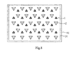
- Fig. 8 schematically illustrates a configuration in which backlight unit is arranged in an array in accordance with yet another embodiment of the invention.
- a backlight unit comprising a light emitting component and a reflection support component, wherein the light emitting component comprises element surfaces disposed obliquely, luminophors are disposed on the element surfaces of the light emitting component, the reflection support component comprises reflective surfaces disposed obliquely.
- a LED light is disposed on each of the inclined element surfaces of a pyramid structure of the light emitting component and each LED light emits light impinging obliquely into a cavity of the backlight unit.
- the reflection support component also forms a pyramid structure, where each inclined surface is a reflective surface made of highly reflective material. Each reflective surface corresponds to an element surface of the light emitting component (substantially corresponding to the LED light on the element surface) and can effectively reflect light emitted by the LED light in the inclined direction.
- the reflection support component may be formed individually in parts and then assembled. Alternatively, the reflection support components may be formed by folding the bottom reflector.
- the reflection support components can be used not only for reflecting the light from the LED lights but also as a support component for supporting components in the upper part of the backlight unit cavity.
- the backlight unit comprises a light emitting component 1, a reflection support component 2, a backplate 41, and a plurality of side plates 42.
- the backplate 41 and the plurality of side plates 42 form a box frame.
- the light emitting component 1 and the reflection support component 2 are disposed in the box frame.
- Sequentially disposed above the box frame are a diffuser plate 61, a first optical film 62 and a second optical film 63.
- the backlight unit further comprises a bottom reflector 31, which covers a part of the backplate 41.
- the light emitting component 1 is disposed on another part of the back plate 41, that is, the light emitting component 1 is disposed on the part of the back plate having no bottom reflector 31 disposed thereon.
- the reflection support component 2 is disposed on the bottom reflector 31. Meanwhile, a top portion of the reflection support component 2 is in contact with the diffuser plate 61 to support the diffuser plate 61 and the first and second optical films 62 and 63 disposed on the diffuser plate.
- the side reflector layer 32 is attached to the side plate 42.
- the backplate indicates where the bottom reflector is disposed
- “another part of” the back plate is where no bottom reflector is disposed.
- the addition of the two parts does not exactly cover the whole backplate surface.
- the disposition of the afore-mentioned bottom reflector, the light emitting component and the backplate is just a preferred embodiment.
- the bottom reflector may cover the whole backplate and the light emitting component may be disposed on the bottom reflector.
- the luminophor in the light emitting component of the invention is a LED, which is not limitative.
- the light emitting component comprises a circuit board 12, a support member 13 and a LED light 11, where the bottom surface of the circuit board is in contact with the backplate and the upper surface of which is in contact with the support member 13.
- the support member 13 is a pyramid that consists of a plurality of slant element surface.
- the LED light 11 comprises a LED chip 15, a seal holder 16 and a seal glue 14.
- Each LED light 11 is fixed to a slant element surface of the support member 13 using a seal holder.
- the bottom surface of the seal holder 16 is connected with the circuit board 12 such that a power is provided for the LED chip 15.
- the LED chip 15 is encapsulated in the seal glue 14.
- the whole light emitting component forms a pyramid structure, the bottom surface of which is in contact with the circuit board 12 and the rest of the slant surfaces function as element surfaces for disposing the LED light 11.
- An angle between each element surface and the circuit board is a light-emission incline of the LED light 11.
- a triangular pyramid (comprising three element surfaces whereupon LED lights may be fixed, except for the bottom surface) is taken as an example for description in Fig. 3 .
- the triangular pyramid is not the only embodiment of the light emitting component pyramid, and a pyramid with more element surfaces may be used in the embodiment as well, such as a rectangular pyramid or a pentagonal pyramid.
- Fig. 4 is a top view of the reflection support component.
- the reflection support component of Fig. 4 also comprises three slant reflection surfaces 21 to 23, each of the reflection surfaces corresponds to a LED light in one of the element surfaces of the light emitting component.
- the optical paths of the lights in the cavity are illustrated in Fig. 5 .
- a part of the light 7 emitted by the LED light 11 is directly transmitted to the diffuser plate 61 and another part of the light is incident on the bottom reflector 31 or a reflection surface of the reflection support component 2 and then transmitted to the diffuser plat 61 after being reflected by the bottom reflector 31 and/or the reflection surface.
- the unreflected light and reflected light are sufficiently mixed in the cavity 5, making the light from the LED light 11 arrived on the diffuser plate 61more uniformly with a shorter mixing height.
- the reflection support component made of a highly reflective material is a pyramid structure in correspondence with the light emitting component.
- the reflection support component not only reflects light but also support the diffuser plate in the backlight unit, thereby making the direct-lit type backlight unit have a flat and stable film structure.
- a width of the LED light is for example - 3mm.
- a size of the light emitting component is required to be big enough for receiving the LED light, a height of light emitting component therefore can be made between 2 to 5mm.
- a height of the reflection support component is determined by the angle of the light emitting component (that is the light-emission incline of the LED light). In order to effectively reflect the light to the diffuser plate, the larger the light-emission incline is, the smaller the angle between the reflection surface and the bottom surface of the reflection support component is, therefore the smaller the height of the reflection support component is.
- the height of the light emitting component is controlled to be between for example 2 to 5mm
- the height of the reflection support component for achieving the aforementioned optical paths is for example about 5 to 20mm.
- the light mixing height of the reflection support component is significantly reduced, which in turn leads to decrease in the height of the backlight unit, thereby reducing the required material, especially the metal material for the backplate. As a result, a lightweight and thin LCD is realized.
- the angle of the light emitting component is limited by the light emission angle of the LED light which is normally 120°.
- the angle of the light emitting component is usually controlled to be 15° to 60°. Accordingly, the angle between the reflection surface and the bottom surface of the reflection support component is for example 10° to 45°.
- a LED light is disposed on each of the slant element surfaces of the light emitting component, and each group of light emitting components form a individual object, therefore, ON/OFF control of individual elements and individual LED lights by the circuit can be easily realized, which in turn makes the contrast in the display region easily controllable.
- Embodiment 2 of the invention is the same as Embodiment 1 except for that the reflection support component may be formed by folding the bottom reflector.
- a bracket 24 disposed on the backplate supports the reflection support component and a plurality of reflection surfaces 21 to 23 of the reflection support component is formed by folding the bottom reflector 31 and fixed at a top end of the frame 24.
- Embodiment 3 of the invention describes a configuration of having a plurality of light emitting components and a plurality of reflection support components in the backlight unit.
- Fig. 7 illustrates a top view of optical paths in the cavity of the backlight unit, in which the lights emitted from the LED light 11 disposed on the support member 13 contains light 71 directly emitted to the cavity space, light 72 emitted to the reflection surfaces of the reflection support components 2, and light 73 reflected by the reflection surfaces. As illustrated in Fig.
- the light emitting components 1 and reflection support components 2 of the direct-lit type backlight unit are arranged as an array, the bottom reflector 31 is disposed on the backplate 41, the light emitting components 1 and reflection support components 2 are disposed on the bottom reflector 31, the light emitting components 1 and reflection support components 2 are alternatively distributed with an equal interval, light emitting surface of each of the light emitting components 1 has a one-to-one correspondence with the reflection surface of the reflection support components 2, and the reflection support components 2 surrounding each of the light emitting components 1 are central symmetrically distributed by taking the light emitting component as a center, thereby forming an overall uniform structure.
- an embodiment of the invention further provides a display device, the display device comprises any of the backlight unit as described above.
- the display device may be a LCD panel, an E-paper, an OLED panel, an LCD television, a LCD monitor, a digital photoframe, a mobile phone, a tablet PC and any other product or component having a display function.
- the light source in the direct-lit type backlight of the invention is designed as being oblique, such that the light from the light source obliquely emits to the surrounding cavity.
- the light incident area of the diffuser plate is increased.
- a small part of the light emits to the reflective surface of the reflection support component and is used again and mixed with the former kind of light.
- the reflection support component combines the optical design and the support structure, which demonstrates a better way of space usage and optical power usage than the conventional single support member.
- the invention ensures the efficiency of the light source, fully utilizes the internal space of the backlight unit, improves the overall optical efficiency of the light source, and effectively reduces the light mixing height of the direct-lit type backlight unit, and facilitates the realization of ultra-thin direct-lit type LCD devices.
- the invention may further have the following configuration:
- a backlight unit the backlight unit comprises:
- the light emitting component comprises a plurality of element surfaces disposed obliquely and a plurality of luminophors disposed on the element surfaces
- the reflection support component comprises a plurality of reflective surfaces disposed obliquely.
- the backlight unit of paragraph (4) further comprising a backplate and a bottom reflector, wherein the backplate supports the whole backlight unit, the bottom reflector covers a part of the backplate, the backlight unit is disposed on another part of the backplate, and the reflection support component is disposed on the bottom reflector.
- the backlight unit comprises a plurality of the light emitting components and a plurality of the reflection support components, wherein the plurality of light emitting components and the plurality of reflection support components are alternatively distributed with equal interval, and the reflection support components surrounding each of the light emitting components are central symmetrically distributed by taking the light emitting component as a center.
- a display device comprising the backlight unit of any of paragraphs 1 to 11.
Applications Claiming Priority (1)
| Application Number | Priority Date | Filing Date | Title |
|---|---|---|---|
| CN2012203615748U CN202647490U (zh) | 2012-07-24 | 2012-07-24 | 背光模组及显示装置 |
Publications (2)
| Publication Number | Publication Date |
|---|---|
| EP2690488A1 true EP2690488A1 (fr) | 2014-01-29 |
| EP2690488B1 EP2690488B1 (fr) | 2016-11-23 |
Family
ID=47416591
Family Applications (1)
| Application Number | Title | Priority Date | Filing Date |
|---|---|---|---|
| EP13174320.5A Not-in-force EP2690488B1 (fr) | 2012-07-24 | 2013-06-28 | Unité de rétroéclairage et dispositif d'affichage |
Country Status (5)
| Country | Link |
|---|---|
| US (1) | US9222664B2 (fr) |
| EP (1) | EP2690488B1 (fr) |
| JP (1) | JP6242605B2 (fr) |
| KR (1) | KR20140013940A (fr) |
| CN (1) | CN202647490U (fr) |
Cited By (1)
| Publication number | Priority date | Publication date | Assignee | Title |
|---|---|---|---|---|
| EP3489744A1 (fr) * | 2016-10-27 | 2019-05-29 | Funai Electric Co., Ltd. | Appareil d'affichage |
Families Citing this family (9)
| Publication number | Priority date | Publication date | Assignee | Title |
|---|---|---|---|---|
| CN102829402B (zh) * | 2012-09-14 | 2015-02-04 | 京东方科技集团股份有限公司 | 直下式背光模组及其显示装置 |
| US10728793B2 (en) * | 2014-06-30 | 2020-07-28 | Telefonakitiebolaget L M Ericsson (Publ) | Aggregation of congestion information |
| CN105093675B (zh) * | 2015-07-30 | 2018-04-13 | 深圳市华星光电技术有限公司 | 一种背光模块 |
| CN107191794B (zh) * | 2017-06-01 | 2020-02-07 | 深圳市华星光电技术有限公司 | 一种灯具 |
| CN110658650A (zh) * | 2018-06-28 | 2020-01-07 | 群创光电股份有限公司 | 显示装置 |
| CN110531552A (zh) * | 2019-08-15 | 2019-12-03 | 安徽康佳电子有限公司 | 一种基于曲面反射结构的直下式背光源 |
| US20230400732A1 (en) * | 2021-03-01 | 2023-12-14 | Beijing Boe Display Technology Co., Ltd. | Light emitting module and display module |
| CN114811531B (zh) * | 2022-04-28 | 2024-03-22 | 富盛光电(吴江)有限公司 | 背光模组及降低背光模组厚度的方法 |
| WO2024050937A1 (fr) * | 2022-09-06 | 2024-03-14 | 瑞仪(广州)光电子器件有限公司 | Module de rétroéclairage de type direct ayant une fonction de support de plaque de diffusion et affichage |
Citations (4)
| Publication number | Priority date | Publication date | Assignee | Title |
|---|---|---|---|---|
| EP1742089A1 (fr) * | 2004-04-12 | 2007-01-10 | The Furukawa Electric Co., Ltd. | Panneau réfléchissant la lumière |
| US20070279936A1 (en) * | 2005-05-30 | 2007-12-06 | Chun-Ho Song | Backlight unit and liquid crystal display |
| US20090147516A1 (en) * | 2007-12-07 | 2009-06-11 | Foxsemicon Integrated Technology, Inc. | Solid illumination device |
| US20100296266A1 (en) * | 2007-09-14 | 2010-11-25 | Osram Gesellschaft mit beschränkter Haftung | Lighting Device |
Family Cites Families (12)
| Publication number | Priority date | Publication date | Assignee | Title |
|---|---|---|---|---|
| TWI282886B (en) * | 2004-04-01 | 2007-06-21 | Au Optronics Corp | Backlight module |
| US7270449B2 (en) * | 2005-02-17 | 2007-09-18 | Alan Uke | Lighting system and method and reflector for use in same |
| KR20060124831A (ko) * | 2005-05-26 | 2006-12-06 | 엘지이노텍 주식회사 | 백라이트 어셈블리 및 이를 구비한 액정표시장치 |
| WO2007043211A1 (fr) * | 2005-10-07 | 2007-04-19 | Sharp Kabushiki Kaisha | Dispositif d'eclairage pour afficheur, et afficheur muni du dispositif d'eclairage |
| JP3142331U (ja) * | 2008-03-03 | 2008-06-12 | 株式会社ギャラックス | 光源反射ユニット |
| TWI364557B (en) * | 2008-05-02 | 2012-05-21 | Chimei Innolux Corp | Light source and backlight module and liquid crystal display device using same |
| CN101581439A (zh) * | 2008-05-16 | 2009-11-18 | 富准精密工业(深圳)有限公司 | 发光二极管照明装置 |
| JP2010108642A (ja) | 2008-10-28 | 2010-05-13 | Sekisui Plastics Co Ltd | 光反射板及びこれを用いた照明体 |
| US20120206660A1 (en) * | 2009-12-01 | 2012-08-16 | Sharp Kabushiki Kaisha | Light source package, illumination device, display device, and television receiving device |
| WO2011158555A1 (fr) * | 2010-06-15 | 2011-12-22 | シャープ株式会社 | Dispositif d'éclairage, dispositif d'affichage et dispositif de réception de télévision |
| WO2012014598A1 (fr) * | 2010-07-30 | 2012-02-02 | シャープ株式会社 | Dispositif d'éclairage, dispositif d'affichage et dispositif de réception de télévision |
| WO2012063676A1 (fr) * | 2010-11-08 | 2012-05-18 | シャープ株式会社 | Dispositif d'éclairage, dispositif d'affichage, et dispositif de réception de télévision |
-
2012
- 2012-07-24 CN CN2012203615748U patent/CN202647490U/zh not_active Expired - Fee Related
-
2013
- 2013-06-26 JP JP2013133464A patent/JP6242605B2/ja not_active Expired - Fee Related
- 2013-06-28 EP EP13174320.5A patent/EP2690488B1/fr not_active Not-in-force
- 2013-07-12 US US13/940,566 patent/US9222664B2/en not_active Expired - Fee Related
- 2013-07-17 KR KR1020130084273A patent/KR20140013940A/ko active Search and Examination
Patent Citations (4)
| Publication number | Priority date | Publication date | Assignee | Title |
|---|---|---|---|---|
| EP1742089A1 (fr) * | 2004-04-12 | 2007-01-10 | The Furukawa Electric Co., Ltd. | Panneau réfléchissant la lumière |
| US20070279936A1 (en) * | 2005-05-30 | 2007-12-06 | Chun-Ho Song | Backlight unit and liquid crystal display |
| US20100296266A1 (en) * | 2007-09-14 | 2010-11-25 | Osram Gesellschaft mit beschränkter Haftung | Lighting Device |
| US20090147516A1 (en) * | 2007-12-07 | 2009-06-11 | Foxsemicon Integrated Technology, Inc. | Solid illumination device |
Cited By (1)
| Publication number | Priority date | Publication date | Assignee | Title |
|---|---|---|---|---|
| EP3489744A1 (fr) * | 2016-10-27 | 2019-05-29 | Funai Electric Co., Ltd. | Appareil d'affichage |
Also Published As
| Publication number | Publication date |
|---|---|
| US9222664B2 (en) | 2015-12-29 |
| JP6242605B2 (ja) | 2017-12-06 |
| KR20140013940A (ko) | 2014-02-05 |
| JP2014026973A (ja) | 2014-02-06 |
| EP2690488B1 (fr) | 2016-11-23 |
| US20140029242A1 (en) | 2014-01-30 |
| CN202647490U (zh) | 2013-01-02 |
Similar Documents
| Publication | Publication Date | Title |
|---|---|---|
| US9222664B2 (en) | Backlight unit and display device | |
| EP3321565B1 (fr) | Module de rétroéclairage et dispositif d'affichage | |
| JP5509154B2 (ja) | 発光装置および表示装置 | |
| US10228589B2 (en) | Backlight unit and liquid crystal display device including the same | |
| EP2913706A1 (fr) | Dispositif d'affichage à cristaux liquides | |
| JP6444339B2 (ja) | 視野角切替バックライトユニット | |
| KR20060038507A (ko) | 액정표시장치용 백라이트 유닛 | |
| JP5228089B2 (ja) | 発光装置および表示装置 | |
| JP2019153436A (ja) | 照明装置および表示装置 | |
| JP2010210891A (ja) | 液晶表示装置 | |
| JP5386551B2 (ja) | 発光装置、表示装置、および反射部材の設計方法 | |
| US20150241020A1 (en) | Optical Member and Display Device Having the Same | |
| JP2012018880A (ja) | 面状照明装置、映像表示装置および光学シート | |
| GB2544895A (en) | Backlight unit and liquid crystal display device including the same | |
| US20120300139A1 (en) | Planar lighting apparatus and liquid crystal display having the same | |
| KR20150065318A (ko) | 백라이트 유닛 및 이를 포함하는 표시장치 | |
| JP2010108601A (ja) | 面状光源及び液晶表示装置 | |
| KR102493918B1 (ko) | 디스플레이 장치 | |
| JP2012243653A (ja) | バックライト装置および表示装置 | |
| JP2014041844A (ja) | バックライトユニット | |
| WO2013015000A1 (fr) | Dispositif électroluminescent et dispositif d'affichage | |
| KR101991124B1 (ko) | 엘이디 어레이 유닛, 이를 갖는 직하형 백라이트 유닛 및 이를 갖는 표시장치 | |
| WO2018199011A1 (fr) | Unité de rétro-éclairage | |
| JP2007059168A (ja) | バックライト | |
| JP5999984B2 (ja) | 照明装置および表示装置 |
Legal Events
| Date | Code | Title | Description |
|---|---|---|---|
| PUAI | Public reference made under article 153(3) epc to a published international application that has entered the european phase |
Free format text: ORIGINAL CODE: 0009012 |
|
| AK | Designated contracting states |
Kind code of ref document: A1 Designated state(s): AL AT BE BG CH CY CZ DE DK EE ES FI FR GB GR HR HU IE IS IT LI LT LU LV MC MK MT NL NO PL PT RO RS SE SI SK SM TR |
|
| AX | Request for extension of the european patent |
Extension state: BA ME |
|
| 17P | Request for examination filed |
Effective date: 20140711 |
|
| RBV | Designated contracting states (corrected) |
Designated state(s): AL AT BE BG CH CY CZ DE DK EE ES FI FR GB GR HR HU IE IS IT LI LT LU LV MC MK MT NL NO PL PT RO RS SE SI SK SM TR |
|
| 17Q | First examination report despatched |
Effective date: 20150608 |
|
| GRAP | Despatch of communication of intention to grant a patent |
Free format text: ORIGINAL CODE: EPIDOSNIGR1 |
|
| INTG | Intention to grant announced |
Effective date: 20160715 |
|
| RAP1 | Party data changed (applicant data changed or rights of an application transferred) |
Owner name: BEIJING BOE CHATANI ELECTRONICS CO., LTD. Owner name: BOE TECHNOLOGY GROUP CO., LTD. |
|
| RIN1 | Information on inventor provided before grant (corrected) |
Inventor name: QIAO, ZHONGLIAN Inventor name: YANG, DONGSHENG Inventor name: ZHENG, WEIXIN |
|
| GRAS | Grant fee paid |
Free format text: ORIGINAL CODE: EPIDOSNIGR3 |
|
| GRAA | (expected) grant |
Free format text: ORIGINAL CODE: 0009210 |
|
| AK | Designated contracting states |
Kind code of ref document: B1 Designated state(s): AL AT BE BG CH CY CZ DE DK EE ES FI FR GB GR HR HU IE IS IT LI LT LU LV MC MK MT NL NO PL PT RO RS SE SI SK SM TR |
|
| REG | Reference to a national code |
Ref country code: GB Ref legal event code: FG4D |
|
| REG | Reference to a national code |
Ref country code: CH Ref legal event code: EP |
|
| REG | Reference to a national code |
Ref country code: IE Ref legal event code: FG4D |
|
| REG | Reference to a national code |
Ref country code: AT Ref legal event code: REF Ref document number: 848443 Country of ref document: AT Kind code of ref document: T Effective date: 20161215 |
|
| REG | Reference to a national code |
Ref country code: NL Ref legal event code: FP |
|
| REG | Reference to a national code |
Ref country code: DE Ref legal event code: R096 Ref document number: 602013014322 Country of ref document: DE |
|
| PG25 | Lapsed in a contracting state [announced via postgrant information from national office to epo] |
Ref country code: LV Free format text: LAPSE BECAUSE OF FAILURE TO SUBMIT A TRANSLATION OF THE DESCRIPTION OR TO PAY THE FEE WITHIN THE PRESCRIBED TIME-LIMIT Effective date: 20161123 |
|
| REG | Reference to a national code |
Ref country code: LT Ref legal event code: MG4D |
|
| REG | Reference to a national code |
Ref country code: AT Ref legal event code: MK05 Ref document number: 848443 Country of ref document: AT Kind code of ref document: T Effective date: 20161123 |
|
| PG25 | Lapsed in a contracting state [announced via postgrant information from national office to epo] |
Ref country code: GR Free format text: LAPSE BECAUSE OF FAILURE TO SUBMIT A TRANSLATION OF THE DESCRIPTION OR TO PAY THE FEE WITHIN THE PRESCRIBED TIME-LIMIT Effective date: 20170224 Ref country code: NO Free format text: LAPSE BECAUSE OF FAILURE TO SUBMIT A TRANSLATION OF THE DESCRIPTION OR TO PAY THE FEE WITHIN THE PRESCRIBED TIME-LIMIT Effective date: 20170223 Ref country code: SE Free format text: LAPSE BECAUSE OF FAILURE TO SUBMIT A TRANSLATION OF THE DESCRIPTION OR TO PAY THE FEE WITHIN THE PRESCRIBED TIME-LIMIT Effective date: 20161123 Ref country code: LT Free format text: LAPSE BECAUSE OF FAILURE TO SUBMIT A TRANSLATION OF THE DESCRIPTION OR TO PAY THE FEE WITHIN THE PRESCRIBED TIME-LIMIT Effective date: 20161123 |
|
| REG | Reference to a national code |
Ref country code: FR Ref legal event code: PLFP Year of fee payment: 5 |
|
| PG25 | Lapsed in a contracting state [announced via postgrant information from national office to epo] |
Ref country code: PT Free format text: LAPSE BECAUSE OF FAILURE TO SUBMIT A TRANSLATION OF THE DESCRIPTION OR TO PAY THE FEE WITHIN THE PRESCRIBED TIME-LIMIT Effective date: 20170323 Ref country code: FI Free format text: LAPSE BECAUSE OF FAILURE TO SUBMIT A TRANSLATION OF THE DESCRIPTION OR TO PAY THE FEE WITHIN THE PRESCRIBED TIME-LIMIT Effective date: 20161123 Ref country code: ES Free format text: LAPSE BECAUSE OF FAILURE TO SUBMIT A TRANSLATION OF THE DESCRIPTION OR TO PAY THE FEE WITHIN THE PRESCRIBED TIME-LIMIT Effective date: 20161123 Ref country code: AT Free format text: LAPSE BECAUSE OF FAILURE TO SUBMIT A TRANSLATION OF THE DESCRIPTION OR TO PAY THE FEE WITHIN THE PRESCRIBED TIME-LIMIT Effective date: 20161123 Ref country code: HR Free format text: LAPSE BECAUSE OF FAILURE TO SUBMIT A TRANSLATION OF THE DESCRIPTION OR TO PAY THE FEE WITHIN THE PRESCRIBED TIME-LIMIT Effective date: 20161123 Ref country code: PL Free format text: LAPSE BECAUSE OF FAILURE TO SUBMIT A TRANSLATION OF THE DESCRIPTION OR TO PAY THE FEE WITHIN THE PRESCRIBED TIME-LIMIT Effective date: 20161123 Ref country code: RS Free format text: LAPSE BECAUSE OF FAILURE TO SUBMIT A TRANSLATION OF THE DESCRIPTION OR TO PAY THE FEE WITHIN THE PRESCRIBED TIME-LIMIT Effective date: 20161123 |
|
| PG25 | Lapsed in a contracting state [announced via postgrant information from national office to epo] |
Ref country code: RO Free format text: LAPSE BECAUSE OF FAILURE TO SUBMIT A TRANSLATION OF THE DESCRIPTION OR TO PAY THE FEE WITHIN THE PRESCRIBED TIME-LIMIT Effective date: 20161123 Ref country code: EE Free format text: LAPSE BECAUSE OF FAILURE TO SUBMIT A TRANSLATION OF THE DESCRIPTION OR TO PAY THE FEE WITHIN THE PRESCRIBED TIME-LIMIT Effective date: 20161123 Ref country code: DK Free format text: LAPSE BECAUSE OF FAILURE TO SUBMIT A TRANSLATION OF THE DESCRIPTION OR TO PAY THE FEE WITHIN THE PRESCRIBED TIME-LIMIT Effective date: 20161123 Ref country code: SK Free format text: LAPSE BECAUSE OF FAILURE TO SUBMIT A TRANSLATION OF THE DESCRIPTION OR TO PAY THE FEE WITHIN THE PRESCRIBED TIME-LIMIT Effective date: 20161123 Ref country code: CZ Free format text: LAPSE BECAUSE OF FAILURE TO SUBMIT A TRANSLATION OF THE DESCRIPTION OR TO PAY THE FEE WITHIN THE PRESCRIBED TIME-LIMIT Effective date: 20161123 |
|
| REG | Reference to a national code |
Ref country code: DE Ref legal event code: R082 Ref document number: 602013014322 Country of ref document: DE Representative=s name: KLUNKER IP PATENTANWAELTE PARTG MBB, DE |
|
| REG | Reference to a national code |
Ref country code: DE Ref legal event code: R097 Ref document number: 602013014322 Country of ref document: DE |
|
| PG25 | Lapsed in a contracting state [announced via postgrant information from national office to epo] |
Ref country code: BE Free format text: LAPSE BECAUSE OF FAILURE TO SUBMIT A TRANSLATION OF THE DESCRIPTION OR TO PAY THE FEE WITHIN THE PRESCRIBED TIME-LIMIT Effective date: 20161123 Ref country code: BG Free format text: LAPSE BECAUSE OF FAILURE TO SUBMIT A TRANSLATION OF THE DESCRIPTION OR TO PAY THE FEE WITHIN THE PRESCRIBED TIME-LIMIT Effective date: 20170223 Ref country code: IT Free format text: LAPSE BECAUSE OF FAILURE TO SUBMIT A TRANSLATION OF THE DESCRIPTION OR TO PAY THE FEE WITHIN THE PRESCRIBED TIME-LIMIT Effective date: 20161123 Ref country code: SM Free format text: LAPSE BECAUSE OF FAILURE TO SUBMIT A TRANSLATION OF THE DESCRIPTION OR TO PAY THE FEE WITHIN THE PRESCRIBED TIME-LIMIT Effective date: 20161123 |
|
| PLBE | No opposition filed within time limit |
Free format text: ORIGINAL CODE: 0009261 |
|
| STAA | Information on the status of an ep patent application or granted ep patent |
Free format text: STATUS: NO OPPOSITION FILED WITHIN TIME LIMIT |
|
| 26N | No opposition filed |
Effective date: 20170824 |
|
| PG25 | Lapsed in a contracting state [announced via postgrant information from national office to epo] |
Ref country code: SI Free format text: LAPSE BECAUSE OF FAILURE TO SUBMIT A TRANSLATION OF THE DESCRIPTION OR TO PAY THE FEE WITHIN THE PRESCRIBED TIME-LIMIT Effective date: 20161123 |
|
| PG25 | Lapsed in a contracting state [announced via postgrant information from national office to epo] |
Ref country code: MC Free format text: LAPSE BECAUSE OF FAILURE TO SUBMIT A TRANSLATION OF THE DESCRIPTION OR TO PAY THE FEE WITHIN THE PRESCRIBED TIME-LIMIT Effective date: 20161123 |
|
| REG | Reference to a national code |
Ref country code: CH Ref legal event code: PL |
|
| REG | Reference to a national code |
Ref country code: IE Ref legal event code: MM4A |
|
| PG25 | Lapsed in a contracting state [announced via postgrant information from national office to epo] |
Ref country code: LU Free format text: LAPSE BECAUSE OF NON-PAYMENT OF DUE FEES Effective date: 20170628 Ref country code: IE Free format text: LAPSE BECAUSE OF NON-PAYMENT OF DUE FEES Effective date: 20170628 Ref country code: CH Free format text: LAPSE BECAUSE OF NON-PAYMENT OF DUE FEES Effective date: 20170630 Ref country code: LI Free format text: LAPSE BECAUSE OF NON-PAYMENT OF DUE FEES Effective date: 20170630 |
|
| REG | Reference to a national code |
Ref country code: FR Ref legal event code: PLFP Year of fee payment: 6 |
|
| PG25 | Lapsed in a contracting state [announced via postgrant information from national office to epo] |
Ref country code: MT Free format text: LAPSE BECAUSE OF NON-PAYMENT OF DUE FEES Effective date: 20170628 |
|
| PG25 | Lapsed in a contracting state [announced via postgrant information from national office to epo] |
Ref country code: HU Free format text: LAPSE BECAUSE OF FAILURE TO SUBMIT A TRANSLATION OF THE DESCRIPTION OR TO PAY THE FEE WITHIN THE PRESCRIBED TIME-LIMIT; INVALID AB INITIO Effective date: 20130628 |
|
| PG25 | Lapsed in a contracting state [announced via postgrant information from national office to epo] |
Ref country code: CY Free format text: LAPSE BECAUSE OF NON-PAYMENT OF DUE FEES Effective date: 20161123 |
|
| PG25 | Lapsed in a contracting state [announced via postgrant information from national office to epo] |
Ref country code: MK Free format text: LAPSE BECAUSE OF FAILURE TO SUBMIT A TRANSLATION OF THE DESCRIPTION OR TO PAY THE FEE WITHIN THE PRESCRIBED TIME-LIMIT Effective date: 20161123 |
|
| PG25 | Lapsed in a contracting state [announced via postgrant information from national office to epo] |
Ref country code: TR Free format text: LAPSE BECAUSE OF FAILURE TO SUBMIT A TRANSLATION OF THE DESCRIPTION OR TO PAY THE FEE WITHIN THE PRESCRIBED TIME-LIMIT Effective date: 20161123 |
|
| PG25 | Lapsed in a contracting state [announced via postgrant information from national office to epo] |
Ref country code: AL Free format text: LAPSE BECAUSE OF FAILURE TO SUBMIT A TRANSLATION OF THE DESCRIPTION OR TO PAY THE FEE WITHIN THE PRESCRIBED TIME-LIMIT Effective date: 20161123 Ref country code: IS Free format text: LAPSE BECAUSE OF FAILURE TO SUBMIT A TRANSLATION OF THE DESCRIPTION OR TO PAY THE FEE WITHIN THE PRESCRIBED TIME-LIMIT Effective date: 20170323 |
|
| PGFP | Annual fee paid to national office [announced via postgrant information from national office to epo] |
Ref country code: DE Payment date: 20210602 Year of fee payment: 9 Ref country code: FR Payment date: 20210513 Year of fee payment: 9 Ref country code: NL Payment date: 20210615 Year of fee payment: 9 |
|
| PGFP | Annual fee paid to national office [announced via postgrant information from national office to epo] |
Ref country code: GB Payment date: 20210602 Year of fee payment: 9 |
|
| REG | Reference to a national code |
Ref country code: DE Ref legal event code: R119 Ref document number: 602013014322 Country of ref document: DE |
|
| REG | Reference to a national code |
Ref country code: NL Ref legal event code: MM Effective date: 20220701 |
|
| GBPC | Gb: european patent ceased through non-payment of renewal fee |
Effective date: 20220628 |
|
| PG25 | Lapsed in a contracting state [announced via postgrant information from national office to epo] |
Ref country code: NL Free format text: LAPSE BECAUSE OF NON-PAYMENT OF DUE FEES Effective date: 20220701 |
|
| PG25 | Lapsed in a contracting state [announced via postgrant information from national office to epo] |
Ref country code: FR Free format text: LAPSE BECAUSE OF NON-PAYMENT OF DUE FEES Effective date: 20220630 |
|
| PG25 | Lapsed in a contracting state [announced via postgrant information from national office to epo] |
Ref country code: GB Free format text: LAPSE BECAUSE OF NON-PAYMENT OF DUE FEES Effective date: 20220628 Ref country code: DE Free format text: LAPSE BECAUSE OF NON-PAYMENT OF DUE FEES Effective date: 20230103 |