EP2688526B1 - Ensemble de courroie de soutien pour dispositifs orthétiques pour extrémités inférieures - Google Patents
Ensemble de courroie de soutien pour dispositifs orthétiques pour extrémités inférieures Download PDFInfo
- Publication number
- EP2688526B1 EP2688526B1 EP12760860.2A EP12760860A EP2688526B1 EP 2688526 B1 EP2688526 B1 EP 2688526B1 EP 12760860 A EP12760860 A EP 12760860A EP 2688526 B1 EP2688526 B1 EP 2688526B1
- Authority
- EP
- European Patent Office
- Prior art keywords
- segment
- linking
- belt assembly
- user
- accordance
- Prior art date
- Legal status (The legal status is an assumption and is not a legal conclusion. Google has not performed a legal analysis and makes no representation as to the accuracy of the status listed.)
- Active
Links
- 230000003319 supportive effect Effects 0.000 title claims description 39
- 210000003141 lower extremity Anatomy 0.000 title claims description 9
- 210000001624 hip Anatomy 0.000 claims description 57
- 210000000689 upper leg Anatomy 0.000 claims description 30
- 210000004394 hip joint Anatomy 0.000 claims description 18
- 238000006073 displacement reaction Methods 0.000 claims description 13
- 239000002775 capsule Substances 0.000 claims description 9
- 230000007246 mechanism Effects 0.000 claims description 9
- 210000003205 muscle Anatomy 0.000 claims description 4
- 238000013519 translation Methods 0.000 claims description 4
- 210000003049 pelvic bone Anatomy 0.000 claims description 3
- 210000002414 leg Anatomy 0.000 description 22
- 238000012546 transfer Methods 0.000 description 17
- 230000033001 locomotion Effects 0.000 description 14
- 210000004197 pelvis Anatomy 0.000 description 7
- 210000003127 knee Anatomy 0.000 description 6
- 210000001503 joint Anatomy 0.000 description 5
- 101000911772 Homo sapiens Hsc70-interacting protein Proteins 0.000 description 4
- 239000004743 Polypropylene Substances 0.000 description 4
- 238000004873 anchoring Methods 0.000 description 4
- 210000003414 extremity Anatomy 0.000 description 4
- 210000002683 foot Anatomy 0.000 description 4
- -1 polypropylene Polymers 0.000 description 4
- 229920001155 polypropylene Polymers 0.000 description 4
- 210000001015 abdomen Anatomy 0.000 description 3
- 210000000988 bone and bone Anatomy 0.000 description 3
- 210000004872 soft tissue Anatomy 0.000 description 3
- 230000009471 action Effects 0.000 description 2
- 210000003484 anatomy Anatomy 0.000 description 2
- 210000001217 buttock Anatomy 0.000 description 2
- 230000006835 compression Effects 0.000 description 2
- 238000007906 compression Methods 0.000 description 2
- 230000006872 improvement Effects 0.000 description 2
- 239000000463 material Substances 0.000 description 2
- 230000003387 muscular Effects 0.000 description 2
- 229920001084 poly(chloroprene) Polymers 0.000 description 2
- 230000000452 restraining effect Effects 0.000 description 2
- 239000007787 solid Substances 0.000 description 2
- 229910000755 6061-T6 aluminium alloy Inorganic materials 0.000 description 1
- 229920000049 Carbon (fiber) Polymers 0.000 description 1
- JOYRKODLDBILNP-UHFFFAOYSA-N Ethyl urethane Chemical compound CCOC(N)=O JOYRKODLDBILNP-UHFFFAOYSA-N 0.000 description 1
- 230000009692 acute damage Effects 0.000 description 1
- XAGFODPZIPBFFR-UHFFFAOYSA-N aluminium Chemical compound [Al] XAGFODPZIPBFFR-UHFFFAOYSA-N 0.000 description 1
- 229910052782 aluminium Inorganic materials 0.000 description 1
- 210000003423 ankle Anatomy 0.000 description 1
- 238000013473 artificial intelligence Methods 0.000 description 1
- 230000000712 assembly Effects 0.000 description 1
- 238000000429 assembly Methods 0.000 description 1
- 239000004917 carbon fiber Substances 0.000 description 1
- 230000008859 change Effects 0.000 description 1
- 230000009693 chronic damage Effects 0.000 description 1
- 230000007423 decrease Effects 0.000 description 1
- 230000007812 deficiency Effects 0.000 description 1
- 238000013461 design Methods 0.000 description 1
- 230000000694 effects Effects 0.000 description 1
- 230000002708 enhancing effect Effects 0.000 description 1
- 210000000629 knee joint Anatomy 0.000 description 1
- 208000027906 leg weakness Diseases 0.000 description 1
- 230000004807 localization Effects 0.000 description 1
- 238000005259 measurement Methods 0.000 description 1
- VNWKTOKETHGBQD-UHFFFAOYSA-N methane Chemical compound C VNWKTOKETHGBQD-UHFFFAOYSA-N 0.000 description 1
- 230000003278 mimic effect Effects 0.000 description 1
- 238000012986 modification Methods 0.000 description 1
- 230000004048 modification Effects 0.000 description 1
- 231100000444 skin lesion Toxicity 0.000 description 1
- 206010040882 skin lesion Diseases 0.000 description 1
- 230000003068 static effect Effects 0.000 description 1
- 210000001519 tissue Anatomy 0.000 description 1
- 238000009941 weaving Methods 0.000 description 1
Images

Classifications
-
- A—HUMAN NECESSITIES
- A61—MEDICAL OR VETERINARY SCIENCE; HYGIENE
- A61F—FILTERS IMPLANTABLE INTO BLOOD VESSELS; PROSTHESES; DEVICES PROVIDING PATENCY TO, OR PREVENTING COLLAPSING OF, TUBULAR STRUCTURES OF THE BODY, e.g. STENTS; ORTHOPAEDIC, NURSING OR CONTRACEPTIVE DEVICES; FOMENTATION; TREATMENT OR PROTECTION OF EYES OR EARS; BANDAGES, DRESSINGS OR ABSORBENT PADS; FIRST-AID KITS
- A61F5/00—Orthopaedic methods or devices for non-surgical treatment of bones or joints; Nursing devices; Anti-rape devices
- A61F5/01—Orthopaedic devices, e.g. splints, casts or braces
- A61F5/0102—Orthopaedic devices, e.g. splints, casts or braces specially adapted for correcting deformities of the limbs or for supporting them; Ortheses, e.g. with articulations
Definitions
- the present disclosure relates to a supportive belt assembly for lower extremity orthotic devices.
- a lower extremity orthotic device such as a knee brace tends to displace itself in various directions away from its main pivotal references, i.e. its respective natural axes of rotation.
- These displacements significantly reduce the efficiency of the orthotic device and even worse, a misalignment of the device with regard to its natural axes of rotation can lead to acute and chronic injuries.
- misalignments arising from the displacement of the device from its original position reduce its capability to adequately stabilize the respective joint-segment body structure and, in the case of a powered orthotic device, its ability to transfer additional biomechanical forces to the body.
- users often use homemade means to try to roughly secure the positioning of their brace with the goal of minimizing its displacement and optimizing its functionality.
- US 1,336,695 discloses a limb and foot brace to provide support to a weakened limb.
- the brace is comprised of a waist portion encircling the waist of the user, a hip portion encircling the hips of the user, a knee portion encircling the leg of the user above and below the knee and a foot piece.
- the various portions and the foot piece are coupled to each other though vertical portions having joints at the hip, knee and ankle.
- EP 0 894 487 A2 discloses a walk assistance apparatus that is comprised of a pelvis/trunk brace encircling the trunk of the user, leg supports having knee joints and being secured to the legs of the user using belts and semi-circular shanks, and feet mechanisms. Motion of the apparatus is controlled by a CO2 tank mounted on the pelvis/trunk brace and various pinion gears and shafts.
- EP 2 163 226 A1 discloses an exoskeleton for safety and control while skiing that is comprised of a rigid first support member encircling the user's waist and a second support member configured to bind to a ski boot, the first and second support members being coupled through a linkage assembly to be located on one or both of the user's legs.
- the linkage assembly is composed of an upper linkage assembly coupled to the leg of the user above the knee and a lower linkage assembly coupled to the leg of the user below the knee, the first support member, upper and lower linkage assemblies being attached using artificial joints.
- One or more clutch assembly operatively connected between elements of the exoskeleton ensure, using signals form movement/pressure sensors, that the support members do not reach dangerous positions.
- the non-limitative illustrative embodiment of the present disclosure provides a supportive belt assembly for lower extremity orthotic devices that eliminates, or at least greatly reduces, undesired displacements of the orthotic devices.
- the supportive belt assembly is a multi-segment belt assembly worn by the user at the waist and hip level, to which are attached one or more orthotic devices.
- the longitudinal and the rotational mobility of the orthotic device is restricted by the capacity of the supportive belt assembly to limit, even eliminate, undesirable shifting.
- the supportive belt assembly enhances the stability of lower extremity orthotic devices on a user and, in the case where the orthotic devices are powered, (i.e. can generate biomechanical efforts at the joints), the quality of the force transfer from the lower extremity orthotic devices to the user's limbs.
- the design of the supportive belt assembly is based upon the concept of the waist as an anchoring central point.
- the supportive belt assembly 10 comprises six major components separated in two groups: a linking segments group and a lateral segments group.
- the linking segments group includes a waist belt 12, a lower-back hips belt (LBHB) 14 and upper thigh contact areas 16, while the lateral segments group includes, on each side of the body of the user, a flexible lateral segment 22 that links the waist belt 12 and the LBHB 14, and a rigid lateral segment 24 that links the LBHB 14 and the upper thigh contact areas 16.
- the components 12, 14, 16, 22 and 24 of the supportive belt assembly 10 are grouped with respect to their function into the assembly.
- the linking segments group (12, 14, 16) gathers together components characterized as supportive elements. Components of this first group are of high importance to deliver the assistive capacities of the orthotic devices to the user.
- the lateral segments group (22, 24) gathers components used to connect together the first group's supportive components.
- Each component of the linking segment group (12, 14, 16) is a direct connection to the human anatomical structure: the waist belt 12 to the waist level transferring part of the load generated by the orthotic devices to the user's pelvic bone; the LBHB 14 to the gluteal level transferring part of the load generated by the orthotic devices to the user's gluteal muscles; and the upper thigh contact areas 16 to the thighs proximal end level transferring part of the load generated by the orthotic devices to the user's thighs proximal ends (i.e. lower buttocks).
- the waist belt 12 is worn at the waist level and closed by a frontal buckle 13.
- Supportive elements have as primary function of creating a mechanical human-machine interface so as to connect to the mechanical bones and muscles structures as directly as possible.
- the efficiency of this mechanical human-machine interface to stabilize the orthotic devices 30 and/or to transfer forces to users has a direct impact on orthotic devices assistive capacities.
- Components of the lateral segments group (22, 24) are used to connect together the supportive elements, i.e. 12, 14 and 16.
- Each flexible lateral segment 22 links the waist belt 12 with the LBHB 14.
- the flexible lateral segment 22 is important to unconstrain hip movements of the user.
- the rigid lateral segments 24 links tips the LBHB 14, via pivot 23, to the upper thigh contact areas 16 and tip of the frame of the orthotic device 30, via pivot 25.
- the purpose of the supportive belt assembly 10 can be summarized in three points: provide vertical stability, provide torsional stability and force transfer.
- the conical shape of the human legs i.e. lower extremities
- the four attachment points 32 of the orthotic device 30 are not sufficient to keep the orthotic device 30 in place in a comfortable manner, neither in movement nor in static position.
- one objective of the supportive belt device 10 is to keep the orthotic device 30 in place, vertically, onto the leg of the user, in order to stabilize the orthotic device 30 and/or to transfer part of the load of the orthotic device 30 to the waist of the user.
- Muscular surfaces onto which the orthotic device 30 lies are more or less firm, depending on the user and on the type of activity carried out.
- the efficiency of the forces transferred from the joint mechanisms and the body segments is reduced by the fact that a part of these additional forces are lost into muscular tissues before providing the expected level of assistance.
- Repeated displacements of the orthotic device 30 on the leg result in the rotation of the orthotic device 30 around the leg of the user, moving inwardly and causing potential skin lesions.
- another objective of the supportive belt assembly 10 is to keep the orthotic device 30 in place in order to prevent it from rotating around the leg of the user.
- a further objective of the supportive belt assembly 10 is to keep the orthotic device 30 in place to prevent the contact areas 32 of the orthotic device to be pushed into the soft tissues of the leg of the user.
- linking segments group (12, 14, 16) and the lateral segments group (22, 24) will now be described further, describing their physical structure, their function as well as how each component contributes to reach the stability and force enhancement objectives described above.
- the waist belt 12 in the illustrative embodiment is about 5 cm in width and is closed by a frontal buckle 13 (see FIG. 1 ).
- the inward surface of the waist belt 12 is covered with VelcroTM loops compatible with potential VelcroTM hooks on the pants of the user to limit undesired movements of the waist belt 12. Tips of the inward surface of the waist belt 12 have VelcroTM hooks which allow an easy adjustment to the waist measurement of the user.
- the waist belt 12 is made of two thick polypropylene straps sewed together, resulting in a high rigidity cross section, able to resist in vertical planes to torsion efforts applied by the weight of the orthotic device 30.
- the waist belt 12 cross section rigidity is required to prevent local deformation of the belt causing considerable discomfort to the user.
- Each orthotic device 30 is linked to the waist belt 12 by the mean of a flexible lateral segment 22 that connects the waist belt 12 and the LBHB 14.
- the pelvis bone offers a solid structure for a comfortable and even distribution of orthotic device 30 load.
- the waist belt 12 transfers part of the load from the orthotic devices 30, approximate 1.5 kg each, to the waist of the user through its flexible lateral segment 22. Thus, downward displacement of the orthotic devices 30 is prevented, and vertical stability objective is reached.
- assistance forces can be transferred to the waist of the user, offering an additional point of contact between the orthotic devices 30 and the user and improving the efficacy of force transfer.
- the role of the LBHB 14 is to provide the rigid lateral segment 24 a fixed position where to be attached at the waist. Since free rotations in the sagittal plane are required for all hips' movements, the LBHB 14 is connected to the frame of the orthotic device 30 via pivots 23 and 25 of the rigid lateral segment 24. This mechanical parts assembly lets the hips' joints free to move while providing a firm attachment to the user's waist.
- the LBHB 14 in the illustrative embodiment is made of a strong and thick polypropylene weaving of about 5 cm in width that can resist substantial torsion efforts. It has to be flexible to conform to the lower back shape during assisting phases so as to offer a surface of contact as large as possible; the largest the surface of contact the more evenly is the load distributed on the user's waist, resulting in a direct comfort improvement. Fitting holes are provided on each side, accommodating various waist sizes. For example, the LBHB 14 can be provided with eight fitting holes accommodating waist sizes from about 71 cm to 101 cm. Pivots 23 and 25 are attached to the LBHB 14 and the frame of the orthotic device 30 through these holes by mean of a mechanical bolt and nut pivot, or any other such attachment.
- the purpose of the LBHL 14 is to keep in place the upper ends of the orthotic devices 30 and to offer a force transfer contact area independent of the waist belt 12.
- the LBHL 14 has no forward section.
- the purpose of the absence of a forward section is to eliminate antero-posterior constraints on pivot 23.
- Pivot 23 is advantageously located above and a little behind the natural hip joint; in which case, a lever of force is created above the mechanical pivot point.
- this lever of force may cause a frontal section to press into the lower abdomen, and thus be an important source of discomfort for the user.
- the LBHB 14 only possesses a rear section. This also explains why the waist belt 12 is minimally connected to the LBHB 14.
- the use of a flexible lateral segment 22 in-between the waist belt 12 and the LBHL 14 offers a force transfer contact area independent of the waist belt 12, and guarantees that no over straining efforts are put on the lower abdomen.
- the attachment point between the LBHB 14 and the upper end of the orthotic device 30 via pivot 25 is located as near as possible to the natural hip joint in the vertical axis. In the horizontal plane, this point is specifically located at the front or a little behind the natural hip joint. It is essential for stability purposes that the point of attachment does not overpass the natural hip joint.
- the LBHB 14 is pressed on the lower back of the user and the position of the attachment point prevents the upper end of the orthotic device 30 from moving forward. Preventing forward displacement as well as displacement around the leg result in a direct stability increase (i.e. torsional stability).
- the upper thigh contact areas 16 allow the transfer of forces from the orthotic device 30 to the proximal end of the user's thighs.
- the upper thigh contact areas 16 are made of urethane reinforced with a carbon fiber mattress and have rounded shape in order to provide a high level of comfort to the user.
- a polypropylene VelcroTM restraining strap 42 surrounds the leg.
- the doubled sided VelcroTM is used as closing system 44 to lock the upper thigh contact areas 16 onto each leg.
- the tips 66 of the upper thigh contact areas 16 each include a groove in order to attach the restraining strap.
- Neoprene cushions 68 are implemented onto the straps to improve user comfort. The "stickiness" characteristic of neoprene material strengthens the resistance to torsion forces in the transversal plane.
- each upper thigh contact area 16 is fully adjustable in the sagittal plane: two degree of freedom in translation which can be locked into place, and one degree in rotation, kept free at all time.
- the vertical translation is possible by means of multiple holes made in the upper brace segment; allowing adjustments for different user heights.
- the antero-posterior translation allows fitting to the user's segment diameter by means of a groove made in the backward tip of the upper thigh contact areas 16.
- the rotation in the sagittal plane is left free to leave user's leg free to move while improving the user's comfort.
- the upper thigh contact areas 16 are specifically located at the buttocks and hamstring muscles junction. This anatomical area is quite close to the pelvic bone structure and consequently reduces compression of soft tissues and undesired orthotic device 30 displacement. The efficacy of force transfer by orthotic devices 30 is then improved, as well as the general user comfort.
- the positioning of the upper thigh contact areas 16 also serves as an anchoring point for the other components of the supportive belt assembly 10, improving the fit onto the user's waist and enhancing the general stability of the orthotic devices 30.
- the flexible lateral segment 22 in the illustrative embodiment takes the form of a polypropylene band of a width of about 2.5 cm, linking the waist belt 12 to the LBHB 14 above pivot 23.
- the main objective of the flexible lateral segment 22 is to transfer the load from the orthotic device 30 to the waist belt 12; the flexible lateral segment 22 is actually used to accomplish the load transfer function from the orthotic device 30 when it is put under tension.
- Torso lateral movements have to be comfortable and free of constraints above the human hip joint. Accordingly, the flexibility characteristic of the flexible lateral segment 22 avoids the undesired situation of having a rigid lateral segment above the human hip joint pushed into torso flesh during transversal plane torso rotations.
- the rigid lateral segment 24 in the illustrative embodiment takes the form of a 6061-T6 aluminum strip of a width of about 3.8 cm.
- the rigid lateral segment 24 links pivot 23 to the proximal upper end of the frame of the orthotic device 30 by means of bolts or other such attachment.
- the function of the rigid lateral segment 24 is to link pivots 23 and 25 of the upper thigh contact areas 16.
- Both supportive elements, the LBHB 14 (positioned through pivot 23) and the upper thigh contact areas 16 (positioned through pivot 25) serve as anchoring elements for the orthotic device 30 in order to transfer assisting force to the user.
- the positioning of pivot 23 on the transversal plane prevents the orthotic device 30 from moving around the user's limbs during assisting phases.
- the rigid lateral segment 24 is provided with holes allowing for length adjustments, which as a result positions pivots 23 and 25 of the upper thigh contact areas 16.
- Deficiencies in stability and force transfer are noticeably reduced using the supportive belt assembly 10, and the biomechanical benefits directly result in a gain in comfort for the user.
- Components making up the supportive belt assembly 10 thus provide orthotic devices 30 with a firm and solid anchoring point, allowing the user to get the most out of each orthotic device's 30 assisting capabilities.
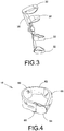
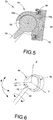
- MHJ mechanical hip joint
- the MHJ 23' consist in a ball joint like mechanism having as a primary function the unconstraining of the pelvis and hips movements.
- the ball joint like mechanism is composed of five main components: an anodized aluminum sphere 52 with and elongated member portion 55, a two piece (54a and 54b) capsule 54, a reduced cross section ball bearing 56, an optional angular position sensor 58 and a housing 59.
- the housing 59 is attached to the LBHB 14, the capsule54 being rotatably connected to the housing 59 via the reduced cross section ball bearing 56.
- the sphere 52 is positioned inside the capsule 54 and its elongated member portion 55 forms the rigid lateral segment 24, protruding from the capsule 54 through groove 53.
- the human hip can execute movements with respect to the three rotational axes. Leaving the user's movements unconstrained requires the MHJ 23' to mimic the three decoupled natural hip rotations.
- the vertical rotation (Z-transverse plane) is allowed by the sphere 52, rotating vertically inside its capsule 54.
- the frontal rotation (Y-transverse plane) is made possible through a groove 53 made perpendicularly with respect to the sagittal plane.
- the MHJ 23' allows the user to move its legs sideward, i.e. sagittal rotation (X-transverse plane), from an angle of about 90 degrees in abduction to an angle of about 10 degrees in adduction.
- the groove 53 decouples the frontal rotation axis (Y-transverse plane) from the sagittal rotation axis (X-transverse plane).
- the groove 53 prevents the sphere 52 from rotating inside its capsule 54 during sagittal axis rotations. It is then the capsule 54 itself that rotates, through the action of the ball bearing 56, with respect to the housing 59.
- This third rotation can be monitored with an optional sensor, for example a magnetic angular position sensor, for artificial intelligence purposes.
- the MHJ 23' also links the orthotic device 30 to the waist belt 12, allowing the load to be properly distributed to the waist belt 12 without over constraining pelvis' and hips' movements.
Claims (13)
- Ensemble ceinture de soutien multi-segments (10) destiné à réduire le déplacement d'une ou de plusieurs orthèses (30) sur les extrémités inférieures d'un utilisateur, la pluralité de segments comprenant :un premier segment de liaison (12) situé, lorsqu'il est utilisé, au niveau de la taille de l'utilisateur pour transférer une partie de la charge générée par la ou les orthèses (30) sur l'os iliaque de l'utilisateur ;une paire de premiers segments latéraux flexibles (22) reliés au premier segment de liaison (12) ;un deuxième segment de liaison (14) situé, lorsqu'il est utilisé, au niveau de la région glutéale de l'utilisateur pour transférer une partie de la charge générée par une ou plusieurs orthèses (30) sur les muscles glutéaux de l'utilisateur, le deuxième segment de liaison (14) étant dépourvu de section avant et étant relié au premier segment de liaison (12) par la paire de premiers segments latéraux flexibles (22) ;Une paire de troisièmes segments de liaison (16) situés, lorsqu'ils sont utilisés, au niveau de l'extrémité proximale des cuisses de l'utilisateur pour transférer une partie de la charge générée par la ou les orthèses (30) sur les extrémités proximales des cuisses de l'utilisateur ; etune paire de seconds segments latéraux rigides (24) qui relient le deuxième segment de liaison (14) et les troisièmes segments de liaison (16), le second segment latéral rigide (24) étant adapté pour être relié à une ou plusieurs orthèses (30).
- Ensemble ceinture de soutien multi-segments (10) selon la revendication 1, dans lequel le premier segment de liaison (12) comprend une ceinture.
- Ensemble ceinture de soutien multi-segments (10) selon l'une quelconque des revendications 1 ou 2, dans lequel le deuxième segment de liaison (14) comprend une ceinture lombaire descendant sur les hanches.
- Ensemble ceinture de soutien multi-segments (10) selon l'une quelconque des revendications 1 à 3, dans lequel chacun des troisièmes segments de liaison (16) comprend des zones de contact (68) sur le haut des cuisses.
- Ensemble ceinture de soutien multi-segments (10) selon la revendication 4, dans lequel les zones de contact (68) sur le haut des cuisses sont réglables dans le plan sagittal.
- Ensemble ceinture de soutien multi-segments (10) selon la revendication 5, dans lequel les zones de contact (68) sur le haut des cuisses sont réglables avec deux degrés de jeu en translation et un degré de jeu en rotation.
- Ensemble ceinture de soutien multi-segments (10) selon l'une quelconque des revendications 1 à 6, dans lequel les seconds segments latéraux rigides (24) sont reliés au deuxième segment de liaison (14) et aux troisièmes segments de liaison (16) via des pivots (23, 25) respectifs.
- Ensemble ceinture de soutien multi-segments (10) selon la revendication 7, dans lequel les pivots (23) reliant les seconds segments latéraux rigides (24) au deuxième segment de liaison (14) sont situés au-dessus de la hanche dans le plan vertical et derrière la hanche dans le plan horizontal.
- Ensemble ceinture de soutien multi-segments (10) selon l'une quelconque des revendications 7 ou 8, dans lequel les pivots (25) reliant le second segment latéral rigide (24) aux troisièmes segments de liaison (16) sont situés au niveau de la hanche dans le plan vertical et derrière la hanche dans le plan horizontal.
- Ensemble ceinture de soutien multi-segments (10) selon l'une quelconque des revendications 7 ou 8, dans lequel les pivots (25) reliant le second segment latéral rigide (24) aux troisièmes segments de liaison (16) sont situés au niveau de la hanche dans le plan vertical et devant la hanche dans le plan horizontal.
- Ensemble ceinture de soutien multi-segments (10) selon l'une quelconque des revendications 7 à 10, dans lequel les pivots (25) reliant le second segment latéral rigide (24) aux troisièmes segments de liaison (16) consistent en des mécanismes de joint à rotule (23').
- Ensemble ceinture de soutien multi-segments (10) selon la revendication 11, dans lequel chacun des mécanismes de joint à rotule (23') est composé d'un logement (59) fixé au deuxième segment de liaison (14), d'une capsule (54) reliée de manière rotative au logement (59), d'une sphère (52) positionnée à l'intérieur de la capsule (54), la sphère (52) ayant une partie d'élément allongé (55) formant le second segment latéral rigide (24) et dépassant de la capsule (54) à travers une rainure allongée (53).
- Ensemble ceinture de soutien multi-segments (10) selon la revendication 12, dans lequel le logement (59) comprend un capteur de position angulaire (58).
Applications Claiming Priority (2)
| Application Number | Priority Date | Filing Date | Title |
|---|---|---|---|
| US201161454632P | 2011-03-21 | 2011-03-21 | |
| PCT/CA2012/000310 WO2012126104A1 (fr) | 2011-03-21 | 2012-03-21 | Ensemble de courroie de soutien pour dispositifs orthétiques pour extrémités inférieures |
Publications (3)
| Publication Number | Publication Date |
|---|---|
| EP2688526A1 EP2688526A1 (fr) | 2014-01-29 |
| EP2688526A4 EP2688526A4 (fr) | 2014-09-10 |
| EP2688526B1 true EP2688526B1 (fr) | 2017-10-11 |
Family
ID=46878581
Family Applications (1)
| Application Number | Title | Priority Date | Filing Date |
|---|---|---|---|
| EP12760860.2A Active EP2688526B1 (fr) | 2011-03-21 | 2012-03-21 | Ensemble de courroie de soutien pour dispositifs orthétiques pour extrémités inférieures |
Country Status (6)
| Country | Link |
|---|---|
| US (1) | US11324621B2 (fr) |
| EP (1) | EP2688526B1 (fr) |
| CA (1) | CA2867742C (fr) |
| ES (1) | ES2656051T3 (fr) |
| NO (1) | NO2791463T3 (fr) |
| WO (1) | WO2012126104A1 (fr) |
Families Citing this family (12)
| Publication number | Priority date | Publication date | Assignee | Title |
|---|---|---|---|---|
| CN105324056A (zh) * | 2013-07-04 | 2016-02-10 | 株式会社Ofrees | 可穿戴式座椅装置 |
| US20150032040A1 (en) * | 2013-07-24 | 2015-01-29 | Gregory Cadichon | Garment-Based System, Construction, and Method for Controllably Bracing a Knee |
| US10561568B1 (en) | 2014-06-19 | 2020-02-18 | Lockheed Martin Corporation | Exoskeleton system providing for a load transfer when a user is standing and kneeling |
| US10548800B1 (en) * | 2015-06-18 | 2020-02-04 | Lockheed Martin Corporation | Exoskeleton pelvic link having hip joint and inguinal joint |
| JP6670861B2 (ja) * | 2015-06-23 | 2020-04-01 | ザ リージェンツ オブ ザ ユニバーシティ オブ カリフォルニア | 外骨格を効率的に着脱するための機構 |
| US10195736B2 (en) | 2015-07-17 | 2019-02-05 | Lockheed Martin Corporation | Variable force exoskeleton hip joint |
| US10518404B2 (en) | 2015-07-17 | 2019-12-31 | Lockheed Martin Corporation | Variable force exoskeleton hip joint |
| US10912346B1 (en) | 2015-11-24 | 2021-02-09 | Lockheed Martin Corporation | Exoskeleton boot and lower link |
| KR102171506B1 (ko) * | 2017-07-25 | 2020-10-29 | 디스크닥터 주식회사 | 고관절 보호대 |
| WO2019022440A1 (fr) * | 2017-07-25 | 2019-01-31 | 디스크닥터 주식회사 | Protecteur d'articulation de la hanche |
| CA3073504A1 (fr) | 2017-08-30 | 2019-03-07 | Lockheed Martin Corporation | Selection de capteur automatique |
| WO2022120466A1 (fr) * | 2020-12-07 | 2022-06-16 | B-Temia Inc. | Ceinture de soutien de structure orthétique |
Family Cites Families (16)
| Publication number | Priority date | Publication date | Assignee | Title |
|---|---|---|---|---|
| US170656A (en) * | 1875-12-07 | Improvement in hip and thigh braces | ||
| US1336695A (en) * | 1917-02-26 | 1920-04-13 | Adam J Gromes | Limb and foot brace |
| US2654365A (en) * | 1949-11-14 | 1953-10-06 | Archie L Whitaker | Combined body and leg brace |
| GB1188647A (en) * | 1966-07-19 | 1970-04-22 | Brian Hartley | Improvements in or relating to Inter-connected Limb Arrangements |
| US4557257A (en) * | 1983-07-21 | 1985-12-10 | Fernandez Jose M | Pneumatic walking brace and operating system |
| US5054476A (en) * | 1989-03-24 | 1991-10-08 | Petrofsky Research, Inc. | Orthosis for assistance in walking |
| US5144943A (en) * | 1990-03-16 | 1992-09-08 | O-Motus, Inc. | Dynamic ankle splint |
| GB9303116D0 (en) * | 1993-02-17 | 1993-03-31 | Young David E | Improvements to lower leg walking orphoses |
| US5718672A (en) * | 1996-10-23 | 1998-02-17 | Gillette Children's Hospital | Dynamic hip splint |
| WO1998047426A1 (fr) * | 1997-04-21 | 1998-10-29 | Virtual Technologies, Inc. | Dispositif et procede de suivi de mouvements du corps, a base de goniometre |
| JPH1142259A (ja) * | 1997-07-28 | 1999-02-16 | Technol Res Assoc Of Medical & Welfare Apparatus | 歩行補助装具 |
| US6039707A (en) * | 1999-02-16 | 2000-03-21 | Crawford; Michael K. | Pelvic support and walking assistance device |
| US6589195B1 (en) * | 2000-05-26 | 2003-07-08 | Orthomerica Products, Inc. | Modular adjustable prophylactic hip orthosis and adduction/abduction joint |
| US6540703B1 (en) * | 2000-11-20 | 2003-04-01 | Max Lerman | Post-operative hip abduction orthosis |
| EP2163226A1 (fr) * | 2007-04-23 | 2010-03-17 | Golden Crab, S.L. | Exosquelette de sécurité et de contrôle pour la pratique du ski |
| CN102046114B (zh) * | 2008-05-28 | 2013-06-05 | 国立大学法人广岛大学 | 骨盆带 |
-
2012
- 2012-03-21 CA CA2867742A patent/CA2867742C/fr active Active
- 2012-03-21 EP EP12760860.2A patent/EP2688526B1/fr active Active
- 2012-03-21 US US14/004,639 patent/US11324621B2/en active Active
- 2012-03-21 WO PCT/CA2012/000310 patent/WO2012126104A1/fr active Application Filing
- 2012-03-21 ES ES12760860.2T patent/ES2656051T3/es active Active
- 2012-12-13 NO NO12857683A patent/NO2791463T3/no unknown
Non-Patent Citations (1)
| Title |
|---|
| None * |
Also Published As
| Publication number | Publication date |
|---|---|
| NO2791463T3 (fr) | 2018-07-28 |
| WO2012126104A1 (fr) | 2012-09-27 |
| US20140094729A1 (en) | 2014-04-03 |
| CA2867742C (fr) | 2020-12-01 |
| US11324621B2 (en) | 2022-05-10 |
| ES2656051T3 (es) | 2018-02-22 |
| EP2688526A1 (fr) | 2014-01-29 |
| EP2688526A4 (fr) | 2014-09-10 |
| CA2867742A1 (fr) | 2012-09-27 |
Similar Documents
| Publication | Publication Date | Title |
|---|---|---|
| EP2688526B1 (fr) | Ensemble de courroie de soutien pour dispositifs orthétiques pour extrémités inférieures | |
| CN111148606B (zh) | 身体接合装置 | |
| US8052629B2 (en) | Multi-fit orthotic and mobility assistance apparatus | |
| US8021316B2 (en) | Weight-bearing lower extremity brace | |
| US8672865B2 (en) | Weight-bearing lower extremity brace | |
| US9820870B2 (en) | Weight-bearing lower extremity brace | |
| US8403872B2 (en) | Weight-bearing lower extremity brace | |
| US5700237A (en) | Device for correcting ankle contractures | |
| US8540655B2 (en) | Weight-bearing lower extremity brace | |
| WO2009144877A1 (fr) | Sangle pelvienne | |
| WO2008036096A1 (fr) | Stabilisateur de hanche dynamique | |
| CN105491979A (zh) | 具有免荷功能的膝关节矫形器 | |
| US20170105864A1 (en) | Triple flexion device | |
| CN210301325U (zh) | 一种仿生柔性脊柱减荷防护装置 | |
| JP3189172B2 (ja) | 骨盤サポータ | |
| US20150080777A1 (en) | Weight-bearing lower extremity brace | |
| EP3162515B1 (fr) | Exoskeleton | |
| CN112294604B (zh) | 一种无动力式全身型负重外骨骼 | |
| CA2543217C (fr) | Enlevement de la pression sur l'attelle de genou | |
| EP4042995A1 (fr) | Dispositif d'interface au niveau du bassin pour un exosquelette | |
| JP2006239343A (ja) | 腰痛ベルト |
Legal Events
| Date | Code | Title | Description |
|---|---|---|---|
| PUAI | Public reference made under article 153(3) epc to a published international application that has entered the european phase |
Free format text: ORIGINAL CODE: 0009012 |
|
| 17P | Request for examination filed |
Effective date: 20131015 |
|
| AK | Designated contracting states |
Kind code of ref document: A1 Designated state(s): AL AT BE BG CH CY CZ DE DK EE ES FI FR GB GR HR HU IE IS IT LI LT LU LV MC MK MT NL NO PL PT RO RS SE SI SK SM TR |
|
| DAX | Request for extension of the european patent (deleted) | ||
| A4 | Supplementary search report drawn up and despatched |
Effective date: 20140812 |
|
| RIC1 | Information provided on ipc code assigned before grant |
Ipc: A61F 5/01 20060101AFI20140806BHEP Ipc: A61F 5/052 20060101ALI20140806BHEP |
|
| 17Q | First examination report despatched |
Effective date: 20160330 |
|
| GRAP | Despatch of communication of intention to grant a patent |
Free format text: ORIGINAL CODE: EPIDOSNIGR1 |
|
| INTG | Intention to grant announced |
Effective date: 20170410 |
|
| GRAS | Grant fee paid |
Free format text: ORIGINAL CODE: EPIDOSNIGR3 |
|
| GRAA | (expected) grant |
Free format text: ORIGINAL CODE: 0009210 |
|
| AK | Designated contracting states |
Kind code of ref document: B1 Designated state(s): AL AT BE BG CH CY CZ DE DK EE ES FI FR GB GR HR HU IE IS IT LI LT LU LV MC MK MT NL NO PL PT RO RS SE SI SK SM TR |
|
| REG | Reference to a national code |
Ref country code: GB Ref legal event code: FG4D |
|
| REG | Reference to a national code |
Ref country code: CH Ref legal event code: EP |
|
| REG | Reference to a national code |
Ref country code: IE Ref legal event code: FG4D |
|
| REG | Reference to a national code |
Ref country code: AT Ref legal event code: REF Ref document number: 935371 Country of ref document: AT Kind code of ref document: T Effective date: 20171115 |
|
| REG | Reference to a national code |
Ref country code: DE Ref legal event code: R096 Ref document number: 602012038420 Country of ref document: DE |
|
| REG | Reference to a national code |
Ref country code: NL Ref legal event code: FP |
|
| REG | Reference to a national code |
Ref country code: SE Ref legal event code: TRGR |
|
| REG | Reference to a national code |
Ref country code: CH Ref legal event code: NV Representative=s name: MICHELI AND CIE SA, CH |
|
| REG | Reference to a national code |
Ref country code: ES Ref legal event code: FG2A Ref document number: 2656051 Country of ref document: ES Kind code of ref document: T3 Effective date: 20180222 |
|
| REG | Reference to a national code |
Ref country code: LT Ref legal event code: MG4D |
|
| REG | Reference to a national code |
Ref country code: NO Ref legal event code: T2 Effective date: 20171011 |
|
| REG | Reference to a national code |
Ref country code: AT Ref legal event code: MK05 Ref document number: 935371 Country of ref document: AT Kind code of ref document: T Effective date: 20171011 |
|
| REG | Reference to a national code |
Ref country code: FR Ref legal event code: PLFP Year of fee payment: 7 |
|
| PG25 | Lapsed in a contracting state [announced via postgrant information from national office to epo] |
Ref country code: LT Free format text: LAPSE BECAUSE OF FAILURE TO SUBMIT A TRANSLATION OF THE DESCRIPTION OR TO PAY THE FEE WITHIN THE PRESCRIBED TIME-LIMIT Effective date: 20171011 |
|
| PG25 | Lapsed in a contracting state [announced via postgrant information from national office to epo] |
Ref country code: AT Free format text: LAPSE BECAUSE OF FAILURE TO SUBMIT A TRANSLATION OF THE DESCRIPTION OR TO PAY THE FEE WITHIN THE PRESCRIBED TIME-LIMIT Effective date: 20171011 Ref country code: RS Free format text: LAPSE BECAUSE OF FAILURE TO SUBMIT A TRANSLATION OF THE DESCRIPTION OR TO PAY THE FEE WITHIN THE PRESCRIBED TIME-LIMIT Effective date: 20171011 Ref country code: BG Free format text: LAPSE BECAUSE OF FAILURE TO SUBMIT A TRANSLATION OF THE DESCRIPTION OR TO PAY THE FEE WITHIN THE PRESCRIBED TIME-LIMIT Effective date: 20180111 Ref country code: LV Free format text: LAPSE BECAUSE OF FAILURE TO SUBMIT A TRANSLATION OF THE DESCRIPTION OR TO PAY THE FEE WITHIN THE PRESCRIBED TIME-LIMIT Effective date: 20171011 Ref country code: HR Free format text: LAPSE BECAUSE OF FAILURE TO SUBMIT A TRANSLATION OF THE DESCRIPTION OR TO PAY THE FEE WITHIN THE PRESCRIBED TIME-LIMIT Effective date: 20171011 Ref country code: IS Free format text: LAPSE BECAUSE OF FAILURE TO SUBMIT A TRANSLATION OF THE DESCRIPTION OR TO PAY THE FEE WITHIN THE PRESCRIBED TIME-LIMIT Effective date: 20180211 Ref country code: GR Free format text: LAPSE BECAUSE OF FAILURE TO SUBMIT A TRANSLATION OF THE DESCRIPTION OR TO PAY THE FEE WITHIN THE PRESCRIBED TIME-LIMIT Effective date: 20180112 |
|
| REG | Reference to a national code |
Ref country code: DE Ref legal event code: R097 Ref document number: 602012038420 Country of ref document: DE |
|
| PG25 | Lapsed in a contracting state [announced via postgrant information from national office to epo] |
Ref country code: SK Free format text: LAPSE BECAUSE OF FAILURE TO SUBMIT A TRANSLATION OF THE DESCRIPTION OR TO PAY THE FEE WITHIN THE PRESCRIBED TIME-LIMIT Effective date: 20171011 Ref country code: CZ Free format text: LAPSE BECAUSE OF FAILURE TO SUBMIT A TRANSLATION OF THE DESCRIPTION OR TO PAY THE FEE WITHIN THE PRESCRIBED TIME-LIMIT Effective date: 20171011 Ref country code: EE Free format text: LAPSE BECAUSE OF FAILURE TO SUBMIT A TRANSLATION OF THE DESCRIPTION OR TO PAY THE FEE WITHIN THE PRESCRIBED TIME-LIMIT Effective date: 20171011 Ref country code: DK Free format text: LAPSE BECAUSE OF FAILURE TO SUBMIT A TRANSLATION OF THE DESCRIPTION OR TO PAY THE FEE WITHIN THE PRESCRIBED TIME-LIMIT Effective date: 20171011 |
|
| PLBE | No opposition filed within time limit |
Free format text: ORIGINAL CODE: 0009261 |
|
| STAA | Information on the status of an ep patent application or granted ep patent |
Free format text: STATUS: NO OPPOSITION FILED WITHIN TIME LIMIT |
|
| PG25 | Lapsed in a contracting state [announced via postgrant information from national office to epo] |
Ref country code: PL Free format text: LAPSE BECAUSE OF FAILURE TO SUBMIT A TRANSLATION OF THE DESCRIPTION OR TO PAY THE FEE WITHIN THE PRESCRIBED TIME-LIMIT Effective date: 20171011 Ref country code: RO Free format text: LAPSE BECAUSE OF FAILURE TO SUBMIT A TRANSLATION OF THE DESCRIPTION OR TO PAY THE FEE WITHIN THE PRESCRIBED TIME-LIMIT Effective date: 20171011 Ref country code: SM Free format text: LAPSE BECAUSE OF FAILURE TO SUBMIT A TRANSLATION OF THE DESCRIPTION OR TO PAY THE FEE WITHIN THE PRESCRIBED TIME-LIMIT Effective date: 20171011 |
|
| 26N | No opposition filed |
Effective date: 20180712 |
|
| PG25 | Lapsed in a contracting state [announced via postgrant information from national office to epo] |
Ref country code: SI Free format text: LAPSE BECAUSE OF FAILURE TO SUBMIT A TRANSLATION OF THE DESCRIPTION OR TO PAY THE FEE WITHIN THE PRESCRIBED TIME-LIMIT Effective date: 20171011 Ref country code: MC Free format text: LAPSE BECAUSE OF FAILURE TO SUBMIT A TRANSLATION OF THE DESCRIPTION OR TO PAY THE FEE WITHIN THE PRESCRIBED TIME-LIMIT Effective date: 20171011 |
|
| REG | Reference to a national code |
Ref country code: BE Ref legal event code: MM Effective date: 20180331 |
|
| REG | Reference to a national code |
Ref country code: IE Ref legal event code: MM4A |
|
| PG25 | Lapsed in a contracting state [announced via postgrant information from national office to epo] |
Ref country code: LU Free format text: LAPSE BECAUSE OF NON-PAYMENT OF DUE FEES Effective date: 20180321 |
|
| PG25 | Lapsed in a contracting state [announced via postgrant information from national office to epo] |
Ref country code: IE Free format text: LAPSE BECAUSE OF NON-PAYMENT OF DUE FEES Effective date: 20180321 |
|
| PG25 | Lapsed in a contracting state [announced via postgrant information from national office to epo] |
Ref country code: BE Free format text: LAPSE BECAUSE OF NON-PAYMENT OF DUE FEES Effective date: 20180331 |
|
| PG25 | Lapsed in a contracting state [announced via postgrant information from national office to epo] |
Ref country code: MT Free format text: LAPSE BECAUSE OF NON-PAYMENT OF DUE FEES Effective date: 20180321 |
|
| PG25 | Lapsed in a contracting state [announced via postgrant information from national office to epo] |
Ref country code: TR Free format text: LAPSE BECAUSE OF FAILURE TO SUBMIT A TRANSLATION OF THE DESCRIPTION OR TO PAY THE FEE WITHIN THE PRESCRIBED TIME-LIMIT Effective date: 20171011 |
|
| PG25 | Lapsed in a contracting state [announced via postgrant information from national office to epo] |
Ref country code: PT Free format text: LAPSE BECAUSE OF FAILURE TO SUBMIT A TRANSLATION OF THE DESCRIPTION OR TO PAY THE FEE WITHIN THE PRESCRIBED TIME-LIMIT Effective date: 20171011 Ref country code: HU Free format text: LAPSE BECAUSE OF FAILURE TO SUBMIT A TRANSLATION OF THE DESCRIPTION OR TO PAY THE FEE WITHIN THE PRESCRIBED TIME-LIMIT; INVALID AB INITIO Effective date: 20120321 |
|
| PG25 | Lapsed in a contracting state [announced via postgrant information from national office to epo] |
Ref country code: CY Free format text: LAPSE BECAUSE OF FAILURE TO SUBMIT A TRANSLATION OF THE DESCRIPTION OR TO PAY THE FEE WITHIN THE PRESCRIBED TIME-LIMIT Effective date: 20171011 Ref country code: MK Free format text: LAPSE BECAUSE OF NON-PAYMENT OF DUE FEES Effective date: 20171011 |
|
| PG25 | Lapsed in a contracting state [announced via postgrant information from national office to epo] |
Ref country code: AL Free format text: LAPSE BECAUSE OF FAILURE TO SUBMIT A TRANSLATION OF THE DESCRIPTION OR TO PAY THE FEE WITHIN THE PRESCRIBED TIME-LIMIT Effective date: 20171011 |
|
| PGFP | Annual fee paid to national office [announced via postgrant information from national office to epo] |
Ref country code: NO Payment date: 20230927 Year of fee payment: 12 Ref country code: NL Payment date: 20230925 Year of fee payment: 12 Ref country code: GB Payment date: 20230925 Year of fee payment: 12 Ref country code: FI Payment date: 20230925 Year of fee payment: 12 Ref country code: ES Payment date: 20230927 Year of fee payment: 12 Ref country code: CH Payment date: 20230925 Year of fee payment: 12 |
|
| PGFP | Annual fee paid to national office [announced via postgrant information from national office to epo] |
Ref country code: SE Payment date: 20230925 Year of fee payment: 12 Ref country code: FR Payment date: 20230925 Year of fee payment: 12 |
|
| PGFP | Annual fee paid to national office [announced via postgrant information from national office to epo] |
Ref country code: IT Payment date: 20230925 Year of fee payment: 12 Ref country code: DE Payment date: 20230929 Year of fee payment: 12 |