EP2688460B1 - Appareil et procédé de modélisation de structures oculaires - Google Patents
Appareil et procédé de modélisation de structures oculaires Download PDFInfo
- Publication number
- EP2688460B1 EP2688460B1 EP12711857.8A EP12711857A EP2688460B1 EP 2688460 B1 EP2688460 B1 EP 2688460B1 EP 12711857 A EP12711857 A EP 12711857A EP 2688460 B1 EP2688460 B1 EP 2688460B1
- Authority
- EP
- European Patent Office
- Prior art keywords
- optical element
- detector
- optical
- eye
- targeted
- Prior art date
- Legal status (The legal status is an assumption and is not a legal conclusion. Google has not performed a legal analysis and makes no representation as to the accuracy of the status listed.)
- Active
Links
Images


Classifications
-
- A—HUMAN NECESSITIES
- A61—MEDICAL OR VETERINARY SCIENCE; HYGIENE
- A61B—DIAGNOSIS; SURGERY; IDENTIFICATION
- A61B3/00—Apparatus for testing the eyes; Instruments for examining the eyes
- A61B3/10—Objective types, i.e. instruments for examining the eyes independent of the patients' perceptions or reactions
- A61B3/14—Arrangements specially adapted for eye photography
-
- A—HUMAN NECESSITIES
- A61—MEDICAL OR VETERINARY SCIENCE; HYGIENE
- A61B—DIAGNOSIS; SURGERY; IDENTIFICATION
- A61B3/00—Apparatus for testing the eyes; Instruments for examining the eyes
- A61B3/10—Objective types, i.e. instruments for examining the eyes independent of the patients' perceptions or reactions
- A61B3/1005—Objective types, i.e. instruments for examining the eyes independent of the patients' perceptions or reactions for measuring distances inside the eye, e.g. thickness of the cornea
-
- A—HUMAN NECESSITIES
- A61—MEDICAL OR VETERINARY SCIENCE; HYGIENE
- A61B—DIAGNOSIS; SURGERY; IDENTIFICATION
- A61B3/00—Apparatus for testing the eyes; Instruments for examining the eyes
- A61B3/10—Objective types, i.e. instruments for examining the eyes independent of the patients' perceptions or reactions
- A61B3/107—Objective types, i.e. instruments for examining the eyes independent of the patients' perceptions or reactions for determining the shape or measuring the curvature of the cornea
-
- A—HUMAN NECESSITIES
- A61—MEDICAL OR VETERINARY SCIENCE; HYGIENE
- A61B—DIAGNOSIS; SURGERY; IDENTIFICATION
- A61B3/00—Apparatus for testing the eyes; Instruments for examining the eyes
- A61B3/10—Objective types, i.e. instruments for examining the eyes independent of the patients' perceptions or reactions
- A61B3/14—Arrangements specially adapted for eye photography
- A61B3/145—Arrangements specially adapted for eye photography by video means
-
- A—HUMAN NECESSITIES
- A61—MEDICAL OR VETERINARY SCIENCE; HYGIENE
- A61B—DIAGNOSIS; SURGERY; IDENTIFICATION
- A61B3/00—Apparatus for testing the eyes; Instruments for examining the eyes
- A61B3/10—Objective types, i.e. instruments for examining the eyes independent of the patients' perceptions or reactions
- A61B3/13—Ophthalmic microscopes
- A61B3/135—Slit-lamp microscopes
-
- A—HUMAN NECESSITIES
- A61—MEDICAL OR VETERINARY SCIENCE; HYGIENE
- A61F—FILTERS IMPLANTABLE INTO BLOOD VESSELS; PROSTHESES; DEVICES PROVIDING PATENCY TO, OR PREVENTING COLLAPSING OF, TUBULAR STRUCTURES OF THE BODY, e.g. STENTS; ORTHOPAEDIC, NURSING OR CONTRACEPTIVE DEVICES; FOMENTATION; TREATMENT OR PROTECTION OF EYES OR EARS; BANDAGES, DRESSINGS OR ABSORBENT PADS; FIRST-AID KITS
- A61F9/00—Methods or devices for treatment of the eyes; Devices for putting-in contact lenses; Devices to correct squinting; Apparatus to guide the blind; Protective devices for the eyes, carried on the body or in the hand
- A61F9/007—Methods or devices for eye surgery
- A61F9/008—Methods or devices for eye surgery using laser
- A61F2009/00878—Planning
Definitions
- the technology described herein relates to ocular modelling.
- Ocular procedures often modify one or more structures of the eye, such as the cornea, lens, or retina. Some procedures involve removing or replacing one or more structures of the eye, or adding an implant. For example, lens replacement surgery involves removing a patient's existing lens and replacing it with a new lens. Some procedures, such as laser vision correction surgery, do not remove or replace existing structures of patient's eye, or add an implant to the eye, but rather re-shape existing structures. Regardless of the type of modification being made (e.g., removal, replacement, insertion, or alteration), the optical performance of the eye is altered by adjustments made to the structures of the eye. Therefore in order to accurately model the structure of any eye, it is necessary to determine the ocular parameters of that eye. These parameters include shape, thickness, and refractive index of ocular structures such as the cornea, the lens, the retina, or any other structures of interest.
- Measuring parameters such as curvatures, or shapes of surfaces, or thicknesses of elements within a patient's eye is traditionally carried out using variations of ultrasound Optical Coherence Tomography (OCT) Interferometery, Purkinje, or Scheimpflug systems.
- OCT ultrasound Optical Coherence Tomography
- Typical Scheimpflug systems facilitate diagnosis of the front chamber of the eye.
- US 6 286 958 B1 entitled "Device for the examination of an eye using a Scheimpflug camera and a slit light projector for photographing slit images of an eye” for example discloses a classic single Scheimpflug system configured for examination of the eye only one meridian at a time.
- US 2009/0190093 entitled “Dual Scheimpflug System for Three-Dimensional Analysis of an Eye” comprises a pair of rotating Scheimpflug cameras positioned perpendicular to one another and rotatable on a platform to generate and display a three dimensional representation of the anterior corneal surface, posterior corneal surface, anterior iris surface and anterior lens surface. While this system provides a dual system, it implements the system using two separate cameras and it is not possible to provide the possibility of allowing two cross sections of the cornea and crystalline lens to be obtained simultaneously.
- a disadvantage of these systems is the inability to measure all the relevant parameters of the eye in a single pass and without having to move or re-orientate the equipment. These systems are unable to measure the front of the lens of the eye without dilating the pupil and also the back surface of the lens under most conditions even with dilation of the pupils. It will be appreciated that dilation affects the accuracy of any measurements made.
- Refractive index is a core parameter needed for ocular modeling. All prior art ignores inter-subject variation in refractive index. Failure to resolve refractive index leads to errors in all measurements beyond the first optical surface (cornea).
- US2004021826 entitled “Combination advanced corneal topography/wave front aberration measurement” discloses a method and apparatus for the simultaneous measurement of the anterior and posterior corneal surfaces, corneal thickness, and optical aberrations of the eye.
- the method employs direct measurements and ray tracing to provide a wide range of measurements for use by the ophthalmic community.
- imaging system for an optical element, the imaging system comprising:
- the optical element may be a multiple element or system.
- Light returning from the optical element may be returning though reflection, scatter, refraction, fluorescence or a combination of these.
- the means for illuminating the targeted optical element preferably comprises at least one source and optical means for altering the direction of incidence of at least one incident light beam on the targeted optical element.
- the system may further comprise means for splitting at least one beam of light emitted from the source, wherein at least two of the resultant split beams have a different angle of incidence relative to the optical axis of the targeted optical element.
- the optical means may comprise at least one or more of a beam shaping lens, mirror with optical power, fold mirror, beam splitter and/or prism.
- the system may further comprise means for changing at least one characteristic of at least one incident light beam on the targeted optical element between consecutive measurements of the detector.
- These may include, for example, means for changing the direction of incidence of at least one incident light beam on the targeted optical element between consecutive measurements of the detector.
- the relative light characteristics of the source might include, but is not limited to, at least one of the following characteristics: spatial and temporal intensity distributions, positions, spatial and temporal linear and/or circular polarizations, phases, wavelengths, temporal and spatial coherences, speckles structures, scattering coefficients and/or the g-anisotropy factors.
- the measured characteristics of the illuminating and/or returning light comprise at least one of spatial and temporal intensity distribution, position, spatial and temporal linear and circular polarization, degree of polarization, phase, wavelength, temporal and spatial coherence, speckles structure, scattering coefficient and g-anisotropy factors.
- the optical device may comprise means for varying the direction of illumination of the optical element relative to the axis of the optical element, being adapted to control the direction of at least one incident light beam.
- Mirrors, lenses, prisms, diffracting gratings and/or coherent fibre bundles may be used to vary or control the direction of illumination of the optical element relative to the axis of the optical element.
- Means may be provided to select different beams illuminating the optical element.
- this might include, but is not limited to apodization of a large illuminating beam using masks in filter wheel and/or a spatial light modulator, selection of various smaller illuminating beams with temporal and/or spatial control.
- the means for directing at least two light beams returning from at least one surface of the illuminated optical element onto the detector may comprise at least one optical component.
- the optical component may comprise one or more of the following: mirrors, lenses, prisms, diffracting gratings, coherent fibre bundles which will receive the returning light at particular angles and positions relative to the axis of the optical element.
- the relative light characteristics of the returning light beams might include, but is not limited to, at least one of the following characteristics: spatial and temporal intensity distributions, positions, spatial and temporal linear and circular polarizations, degree of polarizations, phases, wavelengths, temporal and spatial coherences, speckles structures, scattering coefficients and/or the g-anisotropy factors.
- the or each optical component may be further adapted to control the direction of at least one incident light beam.
- the or each optical component may be used in part to direct the returning light to the detector(s).
- the detector is a CCD, a CMOS sensor, a human eye, a photographic plate, a channel plate array, avalanche photodiodes, a scintillation detector or a photo-multiplying tube.
- the system may further comprise means for changing the position of the detector to focus any or all of the returning light.
- the characteristics of the illuminating and/or returning light are not limited to a single parameter within its own characteristic.
- the characteristics may include at least one of spatial and temporal intensity distributions, positions, spatial and temporal linear and circular polarizations, degree of polarizations, phases, wavelengths, temporal and spatial coherences, speckles structures, scattering coefficients and/or the g-anisotropy factors and may be used sequentially or simultaneously. Other characteristics may be used however.
- the characteristics of the illuminating and/or returning light preferably comprise at least one of spatial and temporal intensity distribution, position, spatial and temporal linear and circular polarization, degree of polarization, phase, wavelength, temporal and spatial coherence, speckles structure, scattering coefficient and g-anisotropy factors.
- the system may further comprise a second detector.
- the first detector and the second detector may lie on different planes with respect to the optical axis of the targeted optical element.
- the first detector and the second detector may however lie on the plane of the optical axis of the targeted optical element.
- Two or more detectors can lie in any plane location and orientation such as to fulfill the Scheimpflug condition. Two detectors may be placed orthogonally.
- the means for illuminating comprises a cross hair light source adapted to generate two beams for projection on the optical element.
- the present invention further provides a method of imaging an optical element, the method comprising the steps of:
- the method may further comprise controlling the direction of the incident light beam.
- the method may further comprise changing or varying the direction of illumination of the optical element relative to the axis of the optical element.
- the method may further comprise changing the position of a detector to focus any or all of the returning light.
- the characteristics of the illuminating and/or returning light comprise at least one of spatial and temporal intensity distribution, position, spatial and temporal linear and circular polarization, degree of polarization, phase, wavelength, temporal and spatial coherence, speckles structure, scattering coefficient and g-anisotropy factors.
- the method may also comprise changing the direction of incidence of at least one incident light beam on the targeted optical element between consecutive measurements.
- the present invention as provided herein provides control of probing beams that fulfil ray tracing criteria and that are capable of being isolated by the telecentric imaging to an accurate model of the eye.
- all meridians are obtained simultaneously or as close to simultaneous as possible.
- simultaneously is considered as less than 1.0 second and preferably under 0.5 seconds.
- the present invention also allows the location of visual axis on images to be determined by having a fixation target eye tracking, or otherwise, which is critical for ray tracing.
- the modelling may indicate the shape and/or location of the structures of the eye, which may be determined using optical methods for determining one or more parameters of the ocular structure of interest, as well as of the structures preceding the ocular structure of interest.
- the one or more parameters may include shape, thickness, distances and refractive index.
- any one of shape, thickness and/or refractive index of an ocular structure of interest may depend to some extent on the directional changes which light employed by the measurement technique undergoes while passing through any ocular structures preceding the structure of interest.
- measurements of shape, thickness, and/or refractive index of ocular structures may be corrected to account for the dependence of the measured values on the other parameters for that structure, as well as on any of the parameters of preceding structures.
- the shapes and locations of ocular structures may be determined, from which an accurate model of the eye may be made.
- the structures may include the cornea, the lens, the retina, or any other structures of interest.
- the shape and location of a structure may be determined by direct measurement of one or more parameters, including shape, thickness, and refractive index, and then correction of any measurements to account for dependence on other parameters of the measured structure or on any parameters of other structures within the eye may be performed. An example is now described in connection with FIG. 1 .
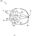
- FIG. 1 provides a simplified representation of an eye 100, including a cornea 102, a lens 104, and a retina 106. These structures are arranged between a front side 108 of the eye, where light enters, and a back side 110 of the eye. Between the cornea 102 and the lens 104 is a volume of aqueous 111. Between the lens 104 and the retina 106 is a volume of vitreous 112. It should be appreciated that the eye 100 is simplified for purposes of illustration, and that eyes typically include more features than those shown in FIG. 1 .
- a structure of interest may be a complete structure (e.g., a lens) or a surface (e.g., the front of the lens) and a parameter may be the shape, thickness, or refractive index of the structure of interest. Any of these three parameters may be of interest either as an ultimate result or as a means for determining other parameters, or for both purposes.
- the shape of the cornea may be of interest as an end result for modelling the cornea, but may also facilitate determination of the refractive index of the cornea.
- modelling the eye 100 may involve determining the shape of one or more surfaces of interest, such as the front surface 114a of the cornea, the back surface 114b of the cornea, etc.
- Topography for example Scheimpflug topography, is one technique that may be used to determine the shapes of such surfaces.
- Purkinje imaging, interferometry and/or optical coherence tomography may also be used.
- modelling the eye 100 to provide locations of the ocular structures may involve determining various distances within the eye.
- the cornea 102 has a thickness T1, between the front surface 114a of the cornea and the back surface 114b of the cornea
- lens 104 has a thickness T2, between the front surface 116a of the lens and the back surface 116b of the lens.
- the cornea and lens are separated by a distance d1 (i.e., the distance from the back surface 114b of the cornea and the front surface 116a of the lens).
- the retina is separated from the back surface 116b of the lens by a distance d2.
- Such distances may be measured using OCT, or other techniques, as the various aspects described herein are not limited in this respect.
- the light employed by such measurement techniques may undergo directional changes induced by the varying indices of refraction of the ocular structures (i.e., refractive index n1 of the cornea, refractive index n2 of the aqueous, refractive index n3 of the lens, and refractive index n4 of the vitreous gel), such that the results may not be accurate if not accounting for such directional changes.
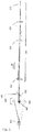
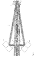
- a modified Purkinje imager such as that shown in Fig. 2 is used to obtain measurements of the ocular parameters.
- an illuminating beam from a collimated source is injected into the system to illuminate mirrors, 210 which are located on the optical axis.
- These mirrors, 210 as shown in Fig. 2 are rod mirrors.
- they are not restricted as such and may also include any reflective element including a combination of prisms (utilizing total internal reflection) with or without mirrors, or glass cones (axicons).
- axicons glass cones
- Illumination of the rod mirrors 210 can be achieved using a beam splitter 205.
- the Mirricon, 206 is configured both for illumination of the eye with collimated beams off-axis and also for imaging the Purkinje reflections working in conjunction with a telecentric optical system or arm 200.
- the Mirricon can deliver the Purkinje reflections to the telecentric system in such a way as to reduce the angular separation of Purkinje reflections from opposite beams such that intrinsic aberrations of the telecentric system are reduced.
- the mirrors 209 are angularly orientated with respect to the mirrors 210 on opposing sides of the optical axis.
- the rays are then directionally reflected from the mirrors 209 towards an eye, 208 at a specific angle of reflection selected such that the Purkinje reflections should be present in the image and separated from each other by sufficient magnitude such that the reflections are resolvable in the crowded group.
- the optimal values for the off-axis angles of the beams depend also on the subject's eye biometry. Further details of the beam angle is provided in relation to Fig. 3 .
- the telecentric imaging arm 200 comprises four main components, including a collimating lens 204, an imaging lens, 202, a telecentric aperture stop, 203 and a detector 201, which may be a charge coupled device (CCD) or other camera.
- the telecentric imaging arm delivers the Purkinje reflections onto the detector.
- the combination of lenses, 202 and 204 and telecentric stop aperture act to block any rays that are not parallel to the optical axis of the system striking the detector, 201.
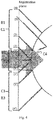
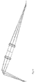
- the mechanics of the Mirricon 206 are described in further detail in Fig. 3 .
- the Mirricon is the beam control unit for the Purkinjie imager in accordance with the present invention.
- Either coherent LASER or incoherent LED light may enter form the left or right of the rod mirrors, 210. As shown in Fig. 3 , these rod mirrors are 45-degree rod mirrors. A gap 301 exists between the rod mirrors allowing a portion of the light to pass directly between the mirrors. Reflected light is also bounced from the rod mirrors 210 to the meridional beam control mirrors, 209. These beam control mirrors then alter the reflected light to generate an input beam angle 302.
- This input beam angle can range from 0 to 90 degrees and can be generated by any combination of the rod mirror and beam control angles provided that the final input beam angle is within the defined range.
- the rod mirrors 210 and the meridional beam control mirrors are disposed on opposing sides of the instrument's optical axis.
- Illumination of the surfaces in question can be done with any wavelength beam of any type, be that coherent laser light, partially coherent LED light or an incoherent broadband source. It is preferable to use the narrowest of bandwidths so that the dispersion of the medium will not be a spectral blur of the spot on the detector.
- this collimated beam can be done by many possible mean, directed beams, a refracted beam by an axicon or a reflected beam by an arrangement of mirrors.
- the mirror solution is of particular interest as it does not induce dispersion or optical aberrations as the axicon would. It also allows for a smaller diameter illumination beam saving on the source intensity and allowing for the telecentric imaging arm to use physically smaller optics.
- Fig. 15 is a representation of the mirrored beam control, here named as the mirricon.
- the central mirrors 2 can be rod mirrors between 10 and 80 degrees while the outer mirrors 1 are the controlling mirrors to generate the angle 7 of the probing beam necessary. These mirrors may have the exact and opposite angle to each other with respect to the optical axis 4.
- the separation between the two inner mirrors 5 must be sufficiently large enough to allow an axialized beam to enter and return, this is of course dependant on the arrangement of the optical system 3 being measured.
- the separation between the two outer mirrors 6 is dependent on the distance to the optical system and the angles to which they probe the surfaces. However, the converse is also true and the separation distance can be left at a set distance and the optical system must then lie within the probing range. It must be noted that the separation is suited to a large value as this will reduce the risk of any interference with mechanical or optical parts.
- the diameters of the mirrors can be designed to whatever is necessary however, the diameter of the inner mirrors determines the diameter of the probing beams. At all times the position and angles of the mirrors must be rotational symmetric about the optical axis for the conditions of the three types of reflections to hold true.
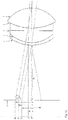
- five broad collimated beams are used to illuminate the eye, namely, B1 and B3 in the vertical meridian (VM), and B2 and B4 in the horizontal meridian (HM) and B0 in the central.
- the use of these five beams allows the required parameters to be determined simultaneously.
- the back reflected light is imaged through the same five channels: C1 and C2 in the VM; and C3 and C4 in the HM;the central C0 From a single surface there are a plurality of reflections, at least four of which are described below. These four reflections are the main types of back reflections, namely:
- channel C3 has five reflections, only three along the vertical direction are shown: CAT from B1, 2', AX from B0, 3', and RET from B3, 4', the remaining two reflections will be of OB type coming from B2 and B4.
- Channel C4 has 5 reflections however only one is shown namely OB from B1, 5". As all five channels have five reflections each, twenty-five reflections in total are available for measurements. Reflections 1 and 3 can be distinguished as inner AX reflection and outer AX reflection, respectively. It will be appreciated that a combination of these reflections may be used in determining and measuring optical surface properties. The combination of the structures described above provide the ability to measure different types of reflections and to reconstruct surfaces in a single pass without the need to obtain multiple measurements individually.
- Figures 9-11 show three different types of back reflections within a Purkinje System, wherein a collimated (possibly infrared) source from 1 illuminates the rod mirrors 2. Rays are then reflected by the rod mirrors going to the Mirricon mirrors 3 and reflected again towards the eye 4 at a specific angle.
- Fig. 9 shows Cat-eye reflection
- Fig. 10 shows Axialised reflection
- Fig. 11 shows Retro reflection.
- a Cat-eye reflection is from the apex of a surface and returns via the mirrors of the opposite side to that which was originally illuminated.
- the cat-eye reflection serves the main purpose to anchor the position of the apex of the surface to be characterized with respect to the Mirricon along its optical axis.
- the cat-reflection gives the position of the eye with respect to the Mirricon, while the cat-eye reflections for the following surfaces gives the information about the central (axial) thickness value entangled with the refractive index of the corresponding medium.
- a Retro reflection occurs when a particular zone of the surface appears normal to the beam and reflects back onto itself by the same path it was illuminated.
- An Axialised reflection is incident at a zone where the angle of reflection is such that it returns to the mirrors parallel to the optical axis of the instrument, and passes through the gap between the rod mirrors. It will be appreciated that axialised reflection also works in the reverse direction, i.e. the surface in question is illuminated via the gap between the rod mirrors and returns via the mirrors at the same angle and positions as when they were illuminated from the mirrors.
- the Retro and Axialised reflections relate information on the curvatures, refractive indices and separations of the surfaces in the eye. The main principle of these reflections is that when rays strike a surface of the eye, to be modelled either via the mirrors or directly, they will return either via the mirrors or directly and pass on to the telecentric arm 200 in Fig. 2 .
- Fig. 12 a generalised structure of the eye and the relevant measurements used in determining this structure their optical parameters are outlined. These are the anterior cornea, 1, the posterior cornea, 2, the iris, 3, the anterior lens, 4 and the posterior lens, 5. are depicted in Figure 5 . To effectively determine the optical surface parameters, heights of aforementioned rays are required. These include as seen in Fig. 12 ,
- Determination of these centroids is worked either on a curve fit of the spot at a threshold or a weighted mean.
- the threshold for the curve fit is set to a brightness level where an interfering second surface reflection can be eliminated or minimized.
- the centroid is then the centre of the circumference of that spot.
- a weighted mean will not work in this scenario as the second overlapping spot will shift the centroid to the centre of gravity of the combined spots. Overlapping spots occur when thicknesses between surfaces are small.
- r c In an exemplary method of determining the radius of the anterior cornea, r c the following equations may be implemented based on the measurements 6 to 15 of Fig 12 determined using for example the ray reflection techniques in Figures 2 to 4 . It will be appreciated that alternatively an optimisation algorithm could also be used to take into account an additional meridian.
- the radius of the anterior cornea is calculated.
- the beam heights are recovered from the distance of separation between the centroids of the reflections from the respective reflections as viewed on the detector 201, example centroid seen in Fig 14 .
- Q surface H surface cos U ⁇ z sin U
- n com is an unknown it is necessary to determine an iterative solution in order to find it and the CCT.
- each successive surface has the preceding surface characterized for its respective index, curvature and distance to the next surface.
- Distances may be determined from the relationship between the beam angle, the anterior corneal curvature calculated, the height of the reflections of the internal structures and refractive indices of the media through which the beams traverse. Refractive indices can be recovered from the time of flight measurements.
- the differential brightness of the reflections given that the mediums before and after the lens (air and aqueous) has a fixed refractive index and the refractive index between the cornea and the lens (aqueous) is also fixed, will allow derivation of refractive index by means of Fresnel equations which are a function of refractive indices, angle of incidence of beams as calculated by the angle of the beams, beam heights and radius of curvature of the two different surfaces.
- refractive indices are functions of wavelengths
- a dispersion curve is used to calculate the change in refractive index given a specific wavelength of source light rays used.
- Another alternative in determining the refractive index could be based on using axialized and oblique reflections along with the cat-eye and retro reflections and then solving for the radius of curvature, thickness and refractive index simultaneously.
- the minimum number of meridians to determine the biconic values of the surface (cylinder) is three, vertical, horizontal and ⁇ 45°. These can also in themselves be rotated, hence the detector will see three rotating lines of spots.
- the number of simultaneous probing meridians is limited only by the mechanics of the system where the mirricon is concerned.
- the Axicon will yield a set of rings instead of spots and the number of meridians is limited then by the resolution of the detector, if not unlimited.
- Scheimpflug system can also be used for the determination of ocular parameters.
- Scheimpflug systems allow for the possibility of diagnosis of the front chamber of the eye and in particular the front surface of the cornea using a large incident beam angle to provide a large field of view and larger curvatures.
- Scheimpflug optical systems adhere to the Scheimpflug principle wherein the plane of the object, the main plane of the camera lens system and the image plane intersect in a common axis. To obtain more than one meridian, traditional instruments are rotated thereby requiring moving parts. The large incident beam angle and large curvatures facilitate this movement without losing accuracy.
- a Scheimpflug system in accordance with the present invention provides for a smaller incident beam angle to facilitate greater depth penetration into the eye.
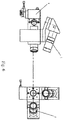
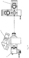
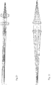
- Figure 6 shows the bottom view (on the left-hand side) and the top view (right-hand side) of a dual-arm Scheimpflug system in accordance with the present invention.
- the first arm, 1 images the vertical meridian of the eye
- the second arm, 2 provides imaging for the horizontal meridian of the eye. Both arms deliver the images of the vertical and horizontal meridians on the same detector, 3.
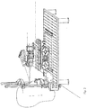
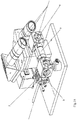
- Figure 7 shows a detailed view of an opto-mechanical system, in particular the illumination unit, which contains a light source unit, 1 that generates two narrow beams.
- a relay lens unit, 2 in conjunction with beam splitters, 3, 4 delivers the illumination into the eye for the vertical and horizontal meridians.
- a subject's eye positioned in front of the beam splitter, 4 is illuminated by the two narrow beams.
- a cross hair light source (forming the two beams) is implemented in the unit, 1 shown in Fig. 7 .
- Rays are converged from more than one meridian to the same detector using the two Scheimpflug arms.
- the need to rotate the instrument is eliminated.
- an eye tracker on the detector axis shown schematically as pupil camera unit 1 in Fig. 8
- the images obtained with the eye tracker provide information about relative position of the two narrow beams (in the vertical and horizontal meridians) relative to the center of the pupil of the eye.
- a cross hair light source can be made by combining two channels, 2 and 3 that contain a vertical slit and a horizontal slit, respectively. These slits help to form very narrow beams projected by the opto mechanical unit (in Fig.7 ) on the cornea.
- Beam splitters, 3 which may be pellicle beam splitters or parallel plate beam splitters, 4, are configured to split pupil camera (eye tracker) and illumination (splitter 3) beams and for bundling of vertical and horizontal slit illumination beams (beam splitter 4).
- the slit illumination beams enables a thin line in two perpendicular directions to be projected within a short period of time (or simultaneously) by synchronizing the light sources in channels (2) and (3) in Fig. 8 .
- the light source can be pulsed so that images of the two meridians in the eye can be obtained simultaneously or one after the other if needed.
- the configuration of the present invention described uses a multiple or dual-arm Scheimpflug system which allows an image of multiple e.g. two and perpendicular) meridians of the eye within a short period of time (or simultaneously) on the same sensor chip or multiple sensor chips to be obtained.
- Figures 16 and 17 show different models of a Scheimpflug camera.
- Figure 18 shows one embodiment of Scheimpflug system in accordance with the present invention.
- the slit 1 projected by optics 2 on to the cornea.
- Beam splitter 3 using for splitting pupil camera and illumination optics beams
- Beam splitter 4 using for bundling of vertical and horizontal slits illumination beams.
- the present application discloses a real dual (90 degrees angle or less between two meridians) Scheimpflug system with single CCD chip allowing recovery of two cross sections of the cornea and crystalline lens simultaneously.
- an A-phase OCT can be combined into a single solution to improve the accuracy of the measurements recorded. It will be appreciated that an A-phase OCT can be used separately to the Scheimpflug or Purkinje systems described above to obtain the axial lengths used in the calculations above.
- a B-Phase OCT may be used to make the relevant measurements necessary for an accurate 3 dimensional model of the eye.
- the present document describes software and hardware methods to achieve the aims as set out in the background to the invention.
- Several alternative optical techniques may also be employed to similar results such as optical coherence tomography, specular interferometry and second harmonics imaging.
- Data proxy to refractive index can also be obtained using non-optical methods such as high-frequency ultrasound and various radiological methods (computed tomography and magnetic resonance imaging).
- a universal software allowing capture and analysis of above device is disclosed.
- Prerequisites of such a software includes a) Correction of optical distortions from preceding surfaces b) recovery of refractive index from dispersion curve of ocular tissue using another optical measurement of another wavelength or by resolving the discrepancy in curvature or distance when compared to another optical measurement of similar wavelength c) Averaging capability of curvatures d) calculating internal ocular parameters such as effective lens position using above output parameters.
- various techniques described herein may therefore be used to design lenses, for example including lens implants.
- the techniques may apply to designing various types of lenses, including, but not limited to, plano, convex, concave, multifocal (refractive, diffractive, etc.), toric, accommodative, prismatic, multiple lens configurations, variable curvature (e.g., aspherical), phakic intraocular lenses, light adjustable lenses, or any combination of those listed.
- one or more of the techniques described herein may be used in the context of planning or performing various types of surgeries.
- Such surgeries may include, but are not limited to, cornea/refractive surgery, lens surgery and retinal surgery.
- Various types of refractive surgery may include, but are not limited to, myopic, hyperopic and presbyopic LASIK, LASEK, or PRK, conductive keratoplasty, radial keratotomy or a combination of the above.
- the methods and apparatus described above may be used to form a model of any number of structures of interest within an eye.
- a complete model of the eye may be formed.
- a model of a single structure e.g., the lens, or a surface of the lens
- the methods and/or apparatus described above may be used to determine a single parameter of interest of a structure.
- the above-described embodiments of the present technology can be implemented in any of numerous ways.
- the embodiments may be implemented using hardware, software or a combination thereof.
- the software code can be executed on any suitable processor or collection of processors, whether provided in a single computer or distributed among multiple computers.
- any component or collection of components that perform the functions described above can be generically considered as one or more controllers that control the above-discussed functions.
- the one or more controllers can be implemented in numerous ways, such as with dedicated hardware, or with general purpose hardware (e.g., one or more processors) that is programmed using microcode or software to perform the functions recited above.
- one implementation of the embodiments of the present technology comprises at least one computer-readable storage medium (e.g., a computer memory, a floppy disk, a compact disk, a tape, a flash drive, etc.) encoded with a computer program (i.e., a plurality of instructions), which, when executed on a processor, performs the above-discussed functions of the embodiments of the present technology.
- the computer-readable storage medium can be transportable such that the program stored thereon can be loaded onto any computer resource to implement the aspects of the present technology discussed herein.
- the reference to a computer program which, when executed, performs the above-discussed functions is not limited to an application program running on a host computer. Rather, the term computer program is used herein in a generic sense to reference any type of computer code (e.g., software or microcode) that can be employed to program a processor to implement the above-discussed aspects of the technology.
- Inventive embodiments of the present technology are directed to each individual feature, system, article, material, kit, and/or method described herein.
- any combination of two or more such features, systems, articles, materials, kits, and/or methods, if such features, systems, articles, materials, kits, and/or methods are not mutually inconsistence, is included within the inventive scope of the present disclosure. All definitions, as defined and used herein, should be understood to control over dictionary definitions, definitions in documents incorporated by reference, and/or ordinary meanings of the defined terms.
- a reference to "A and/or B", when used in conjunction with open-ended language such as “comprising” can refer, in one embodiment, to A only (optionally including elements other than B); in another embodiment, to B only (optionally including elements other than A); in yet another embodiment, to both A and B (optionally including other elements); etc.
- “or” should be understood to have the same meaning as “and/or” as defined above.
- At least one of A and B can refer, in one embodiment, to at least one, optionally including more than one, A, with no B present (and optionally including elements other than B); in another embodiment, to at least one, optionally including more than one, B, with no A present (and optionally including elements other than A); in yet another embodiment, to at least one, optionally including more than one, A, and at least one, optionally including more than, B (and optionally including other elements); etc.
Claims (12)
- Système d'imagerie pour un élément optique, le système d'imagerie comprenant :des moyens pour éclairer un élément optique ciblé (208) avec au moins un faisceau de lumière incident collimaté, les moyens pour éclairer comprenant au moins une source et des moyens optiques pour altérer la direction d'incidence d'au moins un faisceau lumineux incident sur l'élément optique ciblé (208), les moyens optiques pouvant être placés sur l'axe optique de l'élément optique ciblé ; etdes moyens pour diriger au moins deux faisceaux lumineux revenant avec des angles prédéterminés à partir d'au moins une surface de l'élément optique éclairé sur au moins un détecteur (201) ; les moyens pour diriger comprenant au moins un système optique télécentrique (200) et comprenant en outre une pluralité de miroirs (209, 210) orientés angulairement par rapport à l'élément optique ciblé sur des côtés opposés de l'axe optique de sorte que les faisceaux de lumineux revenant sont réfléchis directionnellement par les miroirs (209, 210) en direction de l'élément optique ciblé (208) avec un angle de réflexion spécifique tel que les réflexions de Purkinje sont présentes dans l'image et les faisceaux lumineux revenant sont séparés entre eux d'une amplitude suffisante pour que les réflexions de Purkinje puissent être résolues dans un groupe encombré ;ledit au moins un détecteur étant adapté à mesurer des caractéristiques lumineuses relatives desdits au moins deux faisceaux lumineux revenant et pour calculer au moins un paramètre de l'élément optique en utilisant les caractéristiques mesurées desdits au moins deux faisceaux lumineux revenant.
- Système selon l'une quelconque des revendications précédentes, comprenant en outre des moyens pour séparer au moins un faisceau de lumière émis par la source, dans lequel au moins deux des faisceaux séparés résultants ont un angle d'incidence différent par rapport à l'axe optique de l'élément optique ciblé.
- Système selon la revendication 1, dans lequel les moyens optiques pour altérer la direction d'au moins un faisceau lumineux incident comprennent au moins l'un d'une lentille de mise en forme de faisceau, d'un miroir ayant une puissance optique, d'un miroir de renvoi, d'un séparateur de faisceau ou d'un prisme.
- Système selon la revendication 3, dans lequel les moyens optiques sont en outre adaptés à contrôler la direction d'au moins un faisceau lumineux incident.
- Système selon l'une quelconque des revendications précédentes, dans lequel le détecteur est un capteur CCD, un capteur CMOS, un oeil humain, une plaque photographique, un réseau à plaque rainurée, des photodiodes à avalanche, un détecteur de scintillement ou un tube photomultiplicateur.
- Système selon la revendication 1, comprenant en outre des moyens pour changer la position dudit au moins un détecteur pour focaliser une partie ou la totalité de la lumière renvoyée.
- Système selon l'une quelconque des revendications précédentes, dans lequel les caractéristiques mesurées de l'éclairage et/ou de la lumière renvoyée comprennent au moins l'un d'une distribution d'intensité spatiale et temporelle, d'une position, d'une polarisation spatiale et temporelle linéaire et circulaire, d'un degré de polarisation, d'une phase, d'une longueur d'onde, d'une cohérence temporelle et spatiale, d'une structure de chatoiement, d'un coefficient de diffusion et de facteurs de g-anisotropie.
- Système selon la revendication 1, comprenant en outre un deuxième détecteur, dans lequel le premier détecteur et le deuxième détecteur se trouvent sur des plans différents par rapport à l'axe optique de l'élément optique ciblé ; ou dans lequel le premier détecteur et le deuxième détecteur se trouvent sur le plan de l'axe optique de l'élément optique ciblé.
- Système selon la revendication 8, dans lequel les moyens pour éclairer comprennent une source de lumière à réticule croisé adaptée à générer deux faisceaux pour une projection sur l'élément optique.
- Procédé d'imagerie d'un élément optique, le procédé comprenant les étapes suivantes :éclairer un élément optique ciblé (208) avec au moins un faisceau lumineux incident collimaté, l'éclairage comprenant l'altération de la direction d'incidence dudit au moins un faisceau lumineux incident sur l'élément optique ciblé ; etdiriger au moins deux faisceaux lumineux revenant avec des angles prédéterminés à partir d'au moins une surface de l'élément optique éclairé, sur au moins un détecteur en utilisant au moins un système optique télécentrique et en utilisant en outre une pluralité de miroirs (209, 210) orientés angulairement par rapport à l'élément optique ciblé (208) sur des côtés opposés de l'axe optique de sorte que les faisceaux lumineux revenant sont réfléchis directionnellement par les miroirs (209, 210) en direction de l'élément optique ciblé (208) avec un angle de réflexion spécifique sélectionné de sorte que les réflexions de Purkinje sont présentes dans l'image et les faisceaux lumineux revenant sont séparés entre eux d'une amplitude suffisante pour que les réflexions de Purkinje puissent être résolues dans un groupe encombré ;mesurer les caractéristiques lumineuses relatives desdits au moins deux faisceaux lumineux revenant ; etcalculer au moins un paramètre de l'élément optique (208) en utilisant les caractéristiques mesurées desdits au moins deux faisceaux lumineux revenant.
- Procédé selon la revendication 10, comprenant en outre le changement d'au moins une caractéristique d'au moins un faisceau lumineux incident sur l'élément optique ciblé entre des mesures consécutives.
- Programme informatique contenant des moyens de code de programme informatique adaptés à réaliser toutes les étapes du procédé de l'une quelconque des revendications 10 à 11 lorsque le programme est exécuté sur un ordinateur.
Applications Claiming Priority (2)
| Application Number | Priority Date | Filing Date | Title |
|---|---|---|---|
| US201161467836P | 2011-03-25 | 2011-03-25 | |
| PCT/EP2012/055358 WO2012130818A1 (fr) | 2011-03-25 | 2012-03-26 | Appareil de modélisation de structures oculaires |
Publications (2)
| Publication Number | Publication Date |
|---|---|
| EP2688460A1 EP2688460A1 (fr) | 2014-01-29 |
| EP2688460B1 true EP2688460B1 (fr) | 2018-09-26 |
Family
ID=45928883
Family Applications (1)
| Application Number | Title | Priority Date | Filing Date |
|---|---|---|---|
| EP12711857.8A Active EP2688460B1 (fr) | 2011-03-25 | 2012-03-26 | Appareil et procédé de modélisation de structures oculaires |
Country Status (5)
| Country | Link |
|---|---|
| US (1) | US10952609B2 (fr) |
| EP (1) | EP2688460B1 (fr) |
| JP (2) | JP6301246B2 (fr) |
| ES (1) | ES2701608T3 (fr) |
| WO (1) | WO2012130818A1 (fr) |
Families Citing this family (6)
| Publication number | Priority date | Publication date | Assignee | Title |
|---|---|---|---|---|
| DE102017007974A1 (de) * | 2017-01-27 | 2018-08-02 | Rodenstock Gmbh | Belegung eines Augenmodells zur Optimierung von Brillengläsern mit Messdaten |
| WO2014131917A1 (fr) * | 2013-02-28 | 2014-09-04 | Tecnología Pro Informática, S. L. | Système destiné à obtenir des paramètres de réglage de montures avec des lentilles pour un utilisateur |
| ES2767054T3 (es) | 2015-04-15 | 2020-06-16 | Alcon Inc | Un aparato para modelar estructuras oculares |
| ES2901176T3 (es) * | 2017-12-12 | 2022-03-21 | Alcon Inc | División multihaz utilizando una separación espacial de haz |
| EP3681370A1 (fr) * | 2017-12-21 | 2020-07-22 | Alcon Inc. | Systèmes de diagnostic ophtalmique à vues multiples |
| GB202002009D0 (en) | 2020-02-13 | 2020-04-01 | Univ Liverpool | An imaging device |
Citations (1)
| Publication number | Priority date | Publication date | Assignee | Title |
|---|---|---|---|---|
| US20090002631A1 (en) * | 2007-06-27 | 2009-01-01 | Advanced Medical Optics, Inc. | System and method for measuring corneal topography |
Family Cites Families (27)
| Publication number | Priority date | Publication date | Assignee | Title |
|---|---|---|---|---|
| US4443075A (en) * | 1981-06-26 | 1984-04-17 | Sri International | Stabilized visual system |
| JPS59149125A (ja) * | 1983-02-17 | 1984-08-27 | 工業技術院長 | 水晶体の屈折率測定装置 |
| US4881807A (en) * | 1988-08-05 | 1989-11-21 | Cambridge Instruments, Inc. | Optical alignment system |
| US5225862A (en) * | 1989-02-08 | 1993-07-06 | Canon Kabushiki Kaisha | Visual axis detector using plural reflected image of a light source |
| US5475452A (en) * | 1994-02-24 | 1995-12-12 | Keravision, Inc. | Device and method for mapping objects |
| US5632742A (en) * | 1994-04-25 | 1997-05-27 | Autonomous Technologies Corp. | Eye movement sensing method and system |
| CA2188038C (fr) * | 1994-04-25 | 2005-11-08 | Rudolph W. Frey | Procede et dispositif de detection des mouvements de l'oeil |
| GB2315858A (en) * | 1996-08-01 | 1998-02-11 | Sharp Kk | System for eye detection and gaze direction determination |
| JP4769923B2 (ja) * | 1998-12-10 | 2011-09-07 | カール ツァイス メディテック アクチエンゲゼルシャフト | 眼内レンズの計算に好適な、眼の軸方向長さ及び/又は角膜の曲率及び/又は前房深さを非接触的に測定するための一体化装置 |
| DE29913602U1 (de) | 1999-08-04 | 1999-11-25 | Oculus Optikgeraete Gmbh | Gerät zur Augenuntersuchung mit einer Scheimpflugkamera und einem Spaltprojektor zur Aufnahme von Schnittbildern eines Auges |
| JP2002345755A (ja) * | 2001-05-29 | 2002-12-03 | Menicon Co Ltd | 角膜形状解析方法および角膜形状解析装置 |
| JP4080183B2 (ja) * | 2001-06-26 | 2008-04-23 | 株式会社ニデック | 前眼部撮影装置 |
| JP3703429B2 (ja) * | 2001-12-07 | 2005-10-05 | 株式会社ニデック | 角膜形状測定装置 |
| DE20313745U1 (de) * | 2003-09-02 | 2003-11-20 | Oculus Optikgeraete Gmbh | Ophthalmologisches Analysesystem |
| AU2005261423B2 (en) * | 2004-07-08 | 2011-03-03 | Costruzioni Strumenti Oftalmici C.S.O. S.R.L. | Reflection microscope for examination of the corneal endothelium and method of operating same |
| US20070129775A1 (en) * | 2005-09-19 | 2007-06-07 | Mordaunt David H | System and method for generating treatment patterns |
| EP1785690A1 (fr) * | 2005-11-10 | 2007-05-16 | Haag-Streit Ag | Procédé et dispositif destiné à la détermination de valeurs géométriques d un objet |
| DE102006002001B4 (de) * | 2006-01-16 | 2009-07-23 | Sensomotoric Instruments Gmbh | Verfahren zur Bestimmung der räumlichen Relation eines Auges einer Person bezüglich einer Kameravorrichtung |
| US8356900B2 (en) * | 2006-01-20 | 2013-01-22 | Clarity Medical Systems, Inc. | Large diopter range real time sequential wavefront sensor |
| ITRM20070183A1 (it) * | 2007-04-03 | 2008-10-04 | Optikon 2000 Spa | Apparato oftalmologico multifunzione. |
| JP5073377B2 (ja) * | 2007-06-22 | 2012-11-14 | 株式会社ニデック | 眼科測定装置 |
| JP5448198B2 (ja) | 2007-12-21 | 2014-03-19 | サイファイ メドテック エッセ.エッレ.エッレ. | 眼の3次元解析用デュアルシャインプルーフシステム |
| EP2268192B8 (fr) * | 2008-04-17 | 2022-01-19 | Stichting VUmc | Appareil pour une analyse de forme de cornée et procédé pour déterminer une épaisseur de cornée |
| JP5324839B2 (ja) * | 2008-06-19 | 2013-10-23 | 株式会社トプコン | 光画像計測装置 |
| WO2010003410A1 (fr) * | 2008-07-08 | 2010-01-14 | It-University Of Copenhagen | Procédé de suivi du regard |
| US7878655B2 (en) * | 2008-09-29 | 2011-02-01 | Sifi Diagnostic Spa | Systems and methods for implanting and examining intraocular lens |
| EP2891452B1 (fr) * | 2009-03-26 | 2021-11-03 | Alcon Inc. | Procédés et appareil de modélisation oculaire |
-
2012
- 2012-03-26 EP EP12711857.8A patent/EP2688460B1/fr active Active
- 2012-03-26 WO PCT/EP2012/055358 patent/WO2012130818A1/fr active Application Filing
- 2012-03-26 ES ES12711857T patent/ES2701608T3/es active Active
- 2012-03-26 JP JP2014501566A patent/JP6301246B2/ja active Active
-
2018
- 2018-02-28 JP JP2018034936A patent/JP2018118071A/ja active Pending
- 2018-08-03 US US16/054,653 patent/US10952609B2/en active Active
Patent Citations (1)
| Publication number | Priority date | Publication date | Assignee | Title |
|---|---|---|---|---|
| US20090002631A1 (en) * | 2007-06-27 | 2009-01-01 | Advanced Medical Optics, Inc. | System and method for measuring corneal topography |
Also Published As
| Publication number | Publication date |
|---|---|
| US10952609B2 (en) | 2021-03-23 |
| JP2018118071A (ja) | 2018-08-02 |
| JP2014509910A (ja) | 2014-04-24 |
| WO2012130818A1 (fr) | 2012-10-04 |
| EP2688460A1 (fr) | 2014-01-29 |
| US20180344157A1 (en) | 2018-12-06 |
| JP6301246B2 (ja) | 2018-04-11 |
| ES2701608T3 (es) | 2019-02-25 |
| CN103732129A (zh) | 2014-04-16 |
Similar Documents
| Publication | Publication Date | Title |
|---|---|---|
| US10952609B2 (en) | Apparatus for modelling ocular structures | |
| US10485416B2 (en) | Ocular modeling methods and apparatus | |
| US7659971B2 (en) | Lensometers and wavefront sensors and methods of measuring aberration | |
| US7832864B2 (en) | Inverse optical design | |
| ES2326788T3 (es) | Sistema para trazado de perfil corneal personalizado. | |
| EP3001945B1 (fr) | Lensomètres et capteurs de front d'onde et procédés permettant de mesurer une aberration | |
| ES2767054T3 (es) | Un aparato para modelar estructuras oculares | |
| US20180125355A1 (en) | Technique for performing ophthalmic measurements on an eye | |
| JP2006521157A (ja) | モアレ収差測定器 | |
| US20210338075A1 (en) | Methods and systems for optical coherence tomography scanning of cornea and retina | |
| JP4623899B2 (ja) | 眼バイオメータ | |
| US20150272439A1 (en) | Apparatus for modelling ocular structures | |
| CN101248982A (zh) | 视觉光学分析系统 | |
| US11246484B2 (en) | Methods and systems for eye measurement with in-focus iris and scleral imaging | |
| US20230119409A1 (en) | Refractive index determination by multi-directional ophthalmic image processing | |
| Molebny | Wavefront sensors | |
| CN103732129B (zh) | 用于建模眼部结构的设备 | |
| CN115135228A (zh) | Oct悬韧带成像 |
Legal Events
| Date | Code | Title | Description |
|---|---|---|---|
| PUAI | Public reference made under article 153(3) epc to a published international application that has entered the european phase |
Free format text: ORIGINAL CODE: 0009012 |
|
| 17P | Request for examination filed |
Effective date: 20131002 |
|
| AK | Designated contracting states |
Kind code of ref document: A1 Designated state(s): AL AT BE BG CH CY CZ DE DK EE ES FI FR GB GR HR HU IE IS IT LI LT LU LV MC MK MT NL NO PL PT RO RS SE SI SK SM TR |
|
| DAX | Request for extension of the european patent (deleted) | ||
| RAP1 | Party data changed (applicant data changed or rights of an application transferred) |
Owner name: NOVARTIS AG |
|
| STAA | Information on the status of an ep patent application or granted ep patent |
Free format text: STATUS: EXAMINATION IS IN PROGRESS |
|
| 17Q | First examination report despatched |
Effective date: 20170123 |
|
| GRAP | Despatch of communication of intention to grant a patent |
Free format text: ORIGINAL CODE: EPIDOSNIGR1 |
|
| STAA | Information on the status of an ep patent application or granted ep patent |
Free format text: STATUS: GRANT OF PATENT IS INTENDED |
|
| INTG | Intention to grant announced |
Effective date: 20180423 |
|
| GRAS | Grant fee paid |
Free format text: ORIGINAL CODE: EPIDOSNIGR3 |
|
| GRAA | (expected) grant |
Free format text: ORIGINAL CODE: 0009210 |
|
| STAA | Information on the status of an ep patent application or granted ep patent |
Free format text: STATUS: THE PATENT HAS BEEN GRANTED |
|
| AK | Designated contracting states |
Kind code of ref document: B1 Designated state(s): AL AT BE BG CH CY CZ DE DK EE ES FI FR GB GR HR HU IE IS IT LI LT LU LV MC MK MT NL NO PL PT RO RS SE SI SK SM TR |
|
| REG | Reference to a national code |
Ref country code: GB Ref legal event code: FG4D |
|
| REG | Reference to a national code |
Ref country code: CH Ref legal event code: EP |
|
| REG | Reference to a national code |
Ref country code: AT Ref legal event code: REF Ref document number: 1045040 Country of ref document: AT Kind code of ref document: T Effective date: 20181015 |
|
| REG | Reference to a national code |
Ref country code: IE Ref legal event code: FG4D |
|
| REG | Reference to a national code |
Ref country code: DE Ref legal event code: R096 Ref document number: 602012051484 Country of ref document: DE |
|
| REG | Reference to a national code |
Ref country code: NL Ref legal event code: MP Effective date: 20180926 |
|
| PG25 | Lapsed in a contracting state [announced via postgrant information from national office to epo] |
Ref country code: BG Free format text: LAPSE BECAUSE OF FAILURE TO SUBMIT A TRANSLATION OF THE DESCRIPTION OR TO PAY THE FEE WITHIN THE PRESCRIBED TIME-LIMIT Effective date: 20181226 Ref country code: LT Free format text: LAPSE BECAUSE OF FAILURE TO SUBMIT A TRANSLATION OF THE DESCRIPTION OR TO PAY THE FEE WITHIN THE PRESCRIBED TIME-LIMIT Effective date: 20180926 Ref country code: SE Free format text: LAPSE BECAUSE OF FAILURE TO SUBMIT A TRANSLATION OF THE DESCRIPTION OR TO PAY THE FEE WITHIN THE PRESCRIBED TIME-LIMIT Effective date: 20180926 Ref country code: NO Free format text: LAPSE BECAUSE OF FAILURE TO SUBMIT A TRANSLATION OF THE DESCRIPTION OR TO PAY THE FEE WITHIN THE PRESCRIBED TIME-LIMIT Effective date: 20181226 Ref country code: GR Free format text: LAPSE BECAUSE OF FAILURE TO SUBMIT A TRANSLATION OF THE DESCRIPTION OR TO PAY THE FEE WITHIN THE PRESCRIBED TIME-LIMIT Effective date: 20181227 Ref country code: FI Free format text: LAPSE BECAUSE OF FAILURE TO SUBMIT A TRANSLATION OF THE DESCRIPTION OR TO PAY THE FEE WITHIN THE PRESCRIBED TIME-LIMIT Effective date: 20180926 Ref country code: RS Free format text: LAPSE BECAUSE OF FAILURE TO SUBMIT A TRANSLATION OF THE DESCRIPTION OR TO PAY THE FEE WITHIN THE PRESCRIBED TIME-LIMIT Effective date: 20180926 |
|
| REG | Reference to a national code |
Ref country code: LT Ref legal event code: MG4D |
|
| REG | Reference to a national code |
Ref country code: ES Ref legal event code: FG2A Ref document number: 2701608 Country of ref document: ES Kind code of ref document: T3 Effective date: 20190225 |
|
| PG25 | Lapsed in a contracting state [announced via postgrant information from national office to epo] |
Ref country code: AL Free format text: LAPSE BECAUSE OF FAILURE TO SUBMIT A TRANSLATION OF THE DESCRIPTION OR TO PAY THE FEE WITHIN THE PRESCRIBED TIME-LIMIT Effective date: 20180926 Ref country code: HR Free format text: LAPSE BECAUSE OF FAILURE TO SUBMIT A TRANSLATION OF THE DESCRIPTION OR TO PAY THE FEE WITHIN THE PRESCRIBED TIME-LIMIT Effective date: 20180926 Ref country code: LV Free format text: LAPSE BECAUSE OF FAILURE TO SUBMIT A TRANSLATION OF THE DESCRIPTION OR TO PAY THE FEE WITHIN THE PRESCRIBED TIME-LIMIT Effective date: 20180926 |
|
| REG | Reference to a national code |
Ref country code: AT Ref legal event code: MK05 Ref document number: 1045040 Country of ref document: AT Kind code of ref document: T Effective date: 20180926 |
|
| PG25 | Lapsed in a contracting state [announced via postgrant information from national office to epo] |
Ref country code: PL Free format text: LAPSE BECAUSE OF FAILURE TO SUBMIT A TRANSLATION OF THE DESCRIPTION OR TO PAY THE FEE WITHIN THE PRESCRIBED TIME-LIMIT Effective date: 20180926 Ref country code: EE Free format text: LAPSE BECAUSE OF FAILURE TO SUBMIT A TRANSLATION OF THE DESCRIPTION OR TO PAY THE FEE WITHIN THE PRESCRIBED TIME-LIMIT Effective date: 20180926 Ref country code: AT Free format text: LAPSE BECAUSE OF FAILURE TO SUBMIT A TRANSLATION OF THE DESCRIPTION OR TO PAY THE FEE WITHIN THE PRESCRIBED TIME-LIMIT Effective date: 20180926 Ref country code: NL Free format text: LAPSE BECAUSE OF FAILURE TO SUBMIT A TRANSLATION OF THE DESCRIPTION OR TO PAY THE FEE WITHIN THE PRESCRIBED TIME-LIMIT Effective date: 20180926 Ref country code: CZ Free format text: LAPSE BECAUSE OF FAILURE TO SUBMIT A TRANSLATION OF THE DESCRIPTION OR TO PAY THE FEE WITHIN THE PRESCRIBED TIME-LIMIT Effective date: 20180926 Ref country code: RO Free format text: LAPSE BECAUSE OF FAILURE TO SUBMIT A TRANSLATION OF THE DESCRIPTION OR TO PAY THE FEE WITHIN THE PRESCRIBED TIME-LIMIT Effective date: 20180926 Ref country code: IS Free format text: LAPSE BECAUSE OF FAILURE TO SUBMIT A TRANSLATION OF THE DESCRIPTION OR TO PAY THE FEE WITHIN THE PRESCRIBED TIME-LIMIT Effective date: 20190126 |
|
| PG25 | Lapsed in a contracting state [announced via postgrant information from national office to epo] |
Ref country code: SK Free format text: LAPSE BECAUSE OF FAILURE TO SUBMIT A TRANSLATION OF THE DESCRIPTION OR TO PAY THE FEE WITHIN THE PRESCRIBED TIME-LIMIT Effective date: 20180926 Ref country code: PT Free format text: LAPSE BECAUSE OF FAILURE TO SUBMIT A TRANSLATION OF THE DESCRIPTION OR TO PAY THE FEE WITHIN THE PRESCRIBED TIME-LIMIT Effective date: 20190126 Ref country code: SM Free format text: LAPSE BECAUSE OF FAILURE TO SUBMIT A TRANSLATION OF THE DESCRIPTION OR TO PAY THE FEE WITHIN THE PRESCRIBED TIME-LIMIT Effective date: 20180926 |
|
| REG | Reference to a national code |
Ref country code: DE Ref legal event code: R097 Ref document number: 602012051484 Country of ref document: DE |
|
| PG25 | Lapsed in a contracting state [announced via postgrant information from national office to epo] |
Ref country code: DK Free format text: LAPSE BECAUSE OF FAILURE TO SUBMIT A TRANSLATION OF THE DESCRIPTION OR TO PAY THE FEE WITHIN THE PRESCRIBED TIME-LIMIT Effective date: 20180926 |
|
| PLBE | No opposition filed within time limit |
Free format text: ORIGINAL CODE: 0009261 |
|
| STAA | Information on the status of an ep patent application or granted ep patent |
Free format text: STATUS: NO OPPOSITION FILED WITHIN TIME LIMIT |
|
| 26N | No opposition filed |
Effective date: 20190627 |
|
| PG25 | Lapsed in a contracting state [announced via postgrant information from national office to epo] |
Ref country code: MC Free format text: LAPSE BECAUSE OF FAILURE TO SUBMIT A TRANSLATION OF THE DESCRIPTION OR TO PAY THE FEE WITHIN THE PRESCRIBED TIME-LIMIT Effective date: 20180926 Ref country code: SI Free format text: LAPSE BECAUSE OF FAILURE TO SUBMIT A TRANSLATION OF THE DESCRIPTION OR TO PAY THE FEE WITHIN THE PRESCRIBED TIME-LIMIT Effective date: 20180926 |
|
| REG | Reference to a national code |
Ref country code: CH Ref legal event code: PL |
|
| PG25 | Lapsed in a contracting state [announced via postgrant information from national office to epo] |
Ref country code: LU Free format text: LAPSE BECAUSE OF NON-PAYMENT OF DUE FEES Effective date: 20190326 |
|
| REG | Reference to a national code |
Ref country code: BE Ref legal event code: MM Effective date: 20190331 |
|
| PG25 | Lapsed in a contracting state [announced via postgrant information from national office to epo] |
Ref country code: CH Free format text: LAPSE BECAUSE OF NON-PAYMENT OF DUE FEES Effective date: 20190331 Ref country code: LI Free format text: LAPSE BECAUSE OF NON-PAYMENT OF DUE FEES Effective date: 20190331 Ref country code: IE Free format text: LAPSE BECAUSE OF NON-PAYMENT OF DUE FEES Effective date: 20190326 |
|
| REG | Reference to a national code |
Ref country code: DE Ref legal event code: R082 Ref document number: 602012051484 Country of ref document: DE Representative=s name: WAGNER & GEYER PARTNERSCHAFT MBB PATENT- UND R, DE Ref country code: DE Ref legal event code: R081 Ref document number: 602012051484 Country of ref document: DE Owner name: ALCON INC., CH Free format text: FORMER OWNER: NOVARTIS AG, BASEL, CH |
|
| REG | Reference to a national code |
Ref country code: GB Ref legal event code: 732E Free format text: REGISTERED BETWEEN 20200123 AND 20200129 |
|
| PG25 | Lapsed in a contracting state [announced via postgrant information from national office to epo] |
Ref country code: BE Free format text: LAPSE BECAUSE OF NON-PAYMENT OF DUE FEES Effective date: 20190331 |
|
| PG25 | Lapsed in a contracting state [announced via postgrant information from national office to epo] |
Ref country code: TR Free format text: LAPSE BECAUSE OF FAILURE TO SUBMIT A TRANSLATION OF THE DESCRIPTION OR TO PAY THE FEE WITHIN THE PRESCRIBED TIME-LIMIT Effective date: 20180926 |
|
| REG | Reference to a national code |
Ref country code: ES Ref legal event code: PC2A Owner name: ALCON INC. Effective date: 20200415 |
|
| PG25 | Lapsed in a contracting state [announced via postgrant information from national office to epo] |
Ref country code: MT Free format text: LAPSE BECAUSE OF NON-PAYMENT OF DUE FEES Effective date: 20190326 |
|
| PG25 | Lapsed in a contracting state [announced via postgrant information from national office to epo] |
Ref country code: CY Free format text: LAPSE BECAUSE OF FAILURE TO SUBMIT A TRANSLATION OF THE DESCRIPTION OR TO PAY THE FEE WITHIN THE PRESCRIBED TIME-LIMIT Effective date: 20180926 |
|
| PG25 | Lapsed in a contracting state [announced via postgrant information from national office to epo] |
Ref country code: HU Free format text: LAPSE BECAUSE OF FAILURE TO SUBMIT A TRANSLATION OF THE DESCRIPTION OR TO PAY THE FEE WITHIN THE PRESCRIBED TIME-LIMIT; INVALID AB INITIO Effective date: 20120326 |
|
| PG25 | Lapsed in a contracting state [announced via postgrant information from national office to epo] |
Ref country code: MK Free format text: LAPSE BECAUSE OF FAILURE TO SUBMIT A TRANSLATION OF THE DESCRIPTION OR TO PAY THE FEE WITHIN THE PRESCRIBED TIME-LIMIT Effective date: 20180926 |
|
| PGFP | Annual fee paid to national office [announced via postgrant information from national office to epo] |
Ref country code: FR Payment date: 20230221 Year of fee payment: 12 |
|
| PGFP | Annual fee paid to national office [announced via postgrant information from national office to epo] |
Ref country code: IT Payment date: 20230228 Year of fee payment: 12 Ref country code: GB Payment date: 20230216 Year of fee payment: 12 Ref country code: DE Payment date: 20230222 Year of fee payment: 12 |
|
| P01 | Opt-out of the competence of the unified patent court (upc) registered |
Effective date: 20230503 |
|
| PGFP | Annual fee paid to national office [announced via postgrant information from national office to epo] |
Ref country code: ES Payment date: 20230405 Year of fee payment: 12 |