EP2687675A2 - Moteur à cycle composé - Google Patents
Moteur à cycle composé Download PDFInfo
- Publication number
- EP2687675A2 EP2687675A2 EP13177313.7A EP13177313A EP2687675A2 EP 2687675 A2 EP2687675 A2 EP 2687675A2 EP 13177313 A EP13177313 A EP 13177313A EP 2687675 A2 EP2687675 A2 EP 2687675A2
- Authority
- EP
- European Patent Office
- Prior art keywords
- turbine
- engine
- fluid communication
- rotor
- velocity
- Prior art date
- Legal status (The legal status is an assumption and is not a legal conclusion. Google has not performed a legal analysis and makes no representation as to the accuracy of the status listed.)
- Granted
Links
- 150000001875 compounds Chemical class 0.000 title claims abstract description 43
- 239000012530 fluid Substances 0.000 claims abstract description 29
- 238000004891 communication Methods 0.000 claims abstract description 28
- 238000002485 combustion reaction Methods 0.000 claims abstract description 7
- 238000011144 upstream manufacturing Methods 0.000 claims abstract description 6
- 230000006835 compression Effects 0.000 claims description 12
- 238000007906 compression Methods 0.000 claims description 12
- 239000000446 fuel Substances 0.000 claims description 11
- 230000005540 biological transmission Effects 0.000 claims description 7
- 238000000034 method Methods 0.000 claims description 6
- 238000013329 compounding Methods 0.000 claims description 4
- 230000000063 preceeding effect Effects 0.000 claims 1
- 239000007789 gas Substances 0.000 description 5
- 230000002093 peripheral effect Effects 0.000 description 5
- 239000002826 coolant Substances 0.000 description 3
- 238000010586 diagram Methods 0.000 description 2
- 238000004880 explosion Methods 0.000 description 2
- 239000000203 mixture Substances 0.000 description 2
- 238000012986 modification Methods 0.000 description 2
- 230000004048 modification Effects 0.000 description 2
- 239000002551 biofuel Substances 0.000 description 1
- 230000001010 compromised effect Effects 0.000 description 1
- 238000001816 cooling Methods 0.000 description 1
- -1 diesel Substances 0.000 description 1
- KVIPHDKUOLVVQN-UHFFFAOYSA-N ethene;hydrate Chemical group O.C=C KVIPHDKUOLVVQN-UHFFFAOYSA-N 0.000 description 1
- 239000003350 kerosene Substances 0.000 description 1
- 239000000463 material Substances 0.000 description 1
- 238000010926 purge Methods 0.000 description 1
- 238000011084 recovery Methods 0.000 description 1
- 238000007789 sealing Methods 0.000 description 1
- 239000002699 waste material Substances 0.000 description 1
Images


Classifications
-
- F—MECHANICAL ENGINEERING; LIGHTING; HEATING; WEAPONS; BLASTING
- F02—COMBUSTION ENGINES; HOT-GAS OR COMBUSTION-PRODUCT ENGINE PLANTS
- F02B—INTERNAL-COMBUSTION PISTON ENGINES; COMBUSTION ENGINES IN GENERAL
- F02B53/00—Internal-combustion aspects of rotary-piston or oscillating-piston engines
- F02B53/14—Adaptations of engines for driving, or engine combinations with, other devices
-
- F—MECHANICAL ENGINEERING; LIGHTING; HEATING; WEAPONS; BLASTING
- F01—MACHINES OR ENGINES IN GENERAL; ENGINE PLANTS IN GENERAL; STEAM ENGINES
- F01C—ROTARY-PISTON OR OSCILLATING-PISTON MACHINES OR ENGINES
- F01C11/00—Combinations of two or more machines or engines, each being of rotary-piston or oscillating-piston type
- F01C11/002—Combinations of two or more machines or engines, each being of rotary-piston or oscillating-piston type of similar working principle
-
- F—MECHANICAL ENGINEERING; LIGHTING; HEATING; WEAPONS; BLASTING
- F01—MACHINES OR ENGINES IN GENERAL; ENGINE PLANTS IN GENERAL; STEAM ENGINES
- F01C—ROTARY-PISTON OR OSCILLATING-PISTON MACHINES OR ENGINES
- F01C1/00—Rotary-piston machines or engines
- F01C1/22—Rotary-piston machines or engines of internal-axis type with equidirectional movement of co-operating members at the points of engagement, or with one of the co-operating members being stationary, the inner member having more teeth or tooth- equivalents than the outer member
-
- F—MECHANICAL ENGINEERING; LIGHTING; HEATING; WEAPONS; BLASTING
- F01—MACHINES OR ENGINES IN GENERAL; ENGINE PLANTS IN GENERAL; STEAM ENGINES
- F01C—ROTARY-PISTON OR OSCILLATING-PISTON MACHINES OR ENGINES
- F01C11/00—Combinations of two or more machines or engines, each being of rotary-piston or oscillating-piston type
- F01C11/006—Combinations of two or more machines or engines, each being of rotary-piston or oscillating-piston type of dissimilar working principle
- F01C11/008—Combinations of two or more machines or engines, each being of rotary-piston or oscillating-piston type of dissimilar working principle and of complementary function, e.g. internal combustion engine with supercharger
-
- F—MECHANICAL ENGINEERING; LIGHTING; HEATING; WEAPONS; BLASTING
- F02—COMBUSTION ENGINES; HOT-GAS OR COMBUSTION-PRODUCT ENGINE PLANTS
- F02B—INTERNAL-COMBUSTION PISTON ENGINES; COMBUSTION ENGINES IN GENERAL
- F02B53/00—Internal-combustion aspects of rotary-piston or oscillating-piston engines
- F02B53/10—Fuel supply; Introducing fuel to combustion space
-
- F—MECHANICAL ENGINEERING; LIGHTING; HEATING; WEAPONS; BLASTING
- F02—COMBUSTION ENGINES; HOT-GAS OR COMBUSTION-PRODUCT ENGINE PLANTS
- F02C—GAS-TURBINE PLANTS; AIR INTAKES FOR JET-PROPULSION PLANTS; CONTROLLING FUEL SUPPLY IN AIR-BREATHING JET-PROPULSION PLANTS
- F02C6/00—Plural gas-turbine plants; Combinations of gas-turbine plants with other apparatus; Adaptations of gas- turbine plants for special use
- F02C6/04—Gas-turbine plants providing heated or pressurised working fluid for other apparatus, e.g. without mechanical power output
- F02C6/10—Gas-turbine plants providing heated or pressurised working fluid for other apparatus, e.g. without mechanical power output supplying working fluid to a user, e.g. a chemical process, which returns working fluid to a turbine of the plant
- F02C6/12—Turbochargers, i.e. plants for augmenting mechanical power output of internal-combustion piston engines by increase of charge pressure
-
- F—MECHANICAL ENGINEERING; LIGHTING; HEATING; WEAPONS; BLASTING
- F02—COMBUSTION ENGINES; HOT-GAS OR COMBUSTION-PRODUCT ENGINE PLANTS
- F02C—GAS-TURBINE PLANTS; AIR INTAKES FOR JET-PROPULSION PLANTS; CONTROLLING FUEL SUPPLY IN AIR-BREATHING JET-PROPULSION PLANTS
- F02C6/00—Plural gas-turbine plants; Combinations of gas-turbine plants with other apparatus; Adaptations of gas- turbine plants for special use
- F02C6/20—Adaptations of gas-turbine plants for driving vehicles
-
- F—MECHANICAL ENGINEERING; LIGHTING; HEATING; WEAPONS; BLASTING
- F02—COMBUSTION ENGINES; HOT-GAS OR COMBUSTION-PRODUCT ENGINE PLANTS
- F02B—INTERNAL-COMBUSTION PISTON ENGINES; COMBUSTION ENGINES IN GENERAL
- F02B53/00—Internal-combustion aspects of rotary-piston or oscillating-piston engines
- F02B2053/005—Wankel engines
-
- Y—GENERAL TAGGING OF NEW TECHNOLOGICAL DEVELOPMENTS; GENERAL TAGGING OF CROSS-SECTIONAL TECHNOLOGIES SPANNING OVER SEVERAL SECTIONS OF THE IPC; TECHNICAL SUBJECTS COVERED BY FORMER USPC CROSS-REFERENCE ART COLLECTIONS [XRACs] AND DIGESTS
- Y02—TECHNOLOGIES OR APPLICATIONS FOR MITIGATION OR ADAPTATION AGAINST CLIMATE CHANGE
- Y02T—CLIMATE CHANGE MITIGATION TECHNOLOGIES RELATED TO TRANSPORTATION
- Y02T10/00—Road transport of goods or passengers
- Y02T10/10—Internal combustion engine [ICE] based vehicles
- Y02T10/12—Improving ICE efficiencies
Definitions
- the application relates generally to compound cycle engines and, more particularly, to such compound cycle engines including one or more rotary combustion engine(s).
- Some compound cycle engines include a rotary engine turbocharged and compounded by a turbine located downstream of the turbocharger turbine.
- known compounded rotary engine arrangements typically have limited available power for turbo compounding and/or limited performances, for example on start-up before the turbocharger is running.
- a compound cycle engine comprising: at least one rotary unit with each unit defining an internal combustion engine including a rotor sealingly and rotationally received within a respective housing, each housing defining an inlet port and an exhaust port; a velocity turbine in proximity of each unit and including a rotor supporting a circumferential array of blades extending across a flowpath, the exhaust port of each housing being in fluid communication with the flowpath upstream of the rotor of the velocity turbine, the rotor of the velocity turbine and the rotor of each unit being in driving engagement with a common load; and a turbocharger including a compressor and a pressure turbine in driving engagement through a same shaft, an outlet of the compressor being in fluid communication with the inlet port of each housing, and an inlet of the pressure turbine being in fluid communication with the flowpath downstream of the rotor of the velocity turbine.
- a compound cycle engine comprising: at least one rotary engine having a rotor sealingly and rotationally received within a respective housing having an inlet port and an exhaust port, the rotor of each rotary engine being drivingly engaged to a common load; a velocity turbine in proximity of each rotary engine and having a rotor drivingly engaged to the common load; a respective exhaust pipe providing fluid communication between each exhaust port and the velocity turbine upstream of the rotor thereof; a turbocharger including a compressor and a pressure turbine drivingly engaged to a same shaft; an inlet duct providing fluid communication between an outlet of the compressor and the inlet port of each rotary engine; and a turbine pipe providing fluid communication between an outlet of the velocity turbine and an inlet of the pressure turbine.
- a method of compounding at least one rotary engine comprising: drivingly engaging a pressure turbine and a compressor in a turbocharger; defining a fluid communication between an outlet of the compressor and an inlet port of each rotary engine; defining a fluid communication between an exhaust port of each rotary engine and an inlet of a velocity turbine, including directing the fluid communication onto blades of a rotor of the velocity turbine; defining a fluid communication between an outlet of the velocity turbine and an inlet of the pressure turbine of the turbocharger; and drivingly engaging each rotary engine and the velocity turbine to a common load.
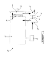
- the compound cycle engine 10 includes one or more rotary units 12, each unit 12 being defined by a rotary internal combustion engine having a rotor sealingly engaged in a respective housing.
- the rotary unit(s) 12 drive a common load.
- the common load includes an output shaft 16 which may be for example connected to a propeller through a reduction gearbox (not shown) and to which the rotor of each unit 12 is engaged.
- the compound cycle engine 10 also includes a turbocharger 18, formed by a compressor 20 and a pressure turbine 22 which are drivingly interconnected by a shaft 24.
- the compressor 20 and the turbine 22 may each be a single-stage device or a multiple-stage device with a single shaft or split on multiple independent shafts in parallel or in series, and may be a centrifugal or axial device.
- the shaft 24 of the turbocharger 18 rotates independently of the common load.
- the compressor 20 of the turbocharger 18 compresses the air before it enters the unit(s) 12.
- the rotary unit(s) 12 form the core of the compound cycle engine 10 and each provide an exhaust flow in the form of exhaust pulses.
- the exhaust flow from the unit(s) 12 is supplied to a power turbine 26 in fluid communication therewith, also driving the common load.
- the power turbine 26 is a velocity type turbine, also known as an impulse turbine, and could be an axial, radial or mixed flow turbine.
- Velocity turbines In a velocity turbine, the fluid is deflected without a significant pressure drop in the blade passages. Velocity turbines thus differ from pressure turbines in that in the pressure drop occurring over the rotor in a pressure turbine is not present in a velocity turbine. Velocity turbines typically have blades with different cross-sections that pressure turbines; for example, blades of pressure turbines usually have a change in flow area as the working fluid circulates therethrough, while blades of velocity turbines usually have a constant flow area; blades of pressure turbines are usually not symmetrical about the plane of the rotating disc, while blades of velocity turbines usually are. Each blade of the velocity turbine 26 thus forms a bucket pushed by the exhaust flow.
- the rotor of the power turbine 26 is rotated by the forces created on the blades by the impingement against them of the exhaust pulses. As such, the kinetic energy provided by each exhaust pulse is used to drive the rotor of the power turbine 26 while imposing minimum back pressure on the rotary unit(s) 12.
- the power turbine 26 is connected to the output shaft 16 through an appropriate type of transmission 28, for example a planetary, star, offset or angular gear system.
- the outlet of the power turbine 26 is in fluid communication with an inlet of the turbocharger turbine 22. Energy is extracted from the exhaust gas exiting the power turbine 26 by the turbocharger turbine 22 to drive the compressor 20 via the connecting shaft 24.
- the air may optionally circulate through an intercooler between the compressor 20 and the unit(s) 12, and the compound cycle engine 10 also includes a cooling system, including for example a circulation system for a coolant (e.g. water-ethylene, oil, air) to cool the housing of each unit 12, an oil coolant for the internal mechanical parts of the unit(s) 12, one or more coolant heat exchangers, etc.
- a coolant e.g. water-ethylene, oil, air
- each unit 12 which in a particular embodiment are common rail fuel injectors, communicate with a source 30 of Heavy fuel (e.g. diesel, kerosene (jet fuel), equivalent biofuel), and deliver the heavy fuel into the unit(s) 12 such that the combustion chamber is stratified with a rich fuel-air mixture near the ignition source and a leaner mixture elsewhere.
- Heavy fuel e.g. diesel, kerosene (jet fuel), equivalent biofuel
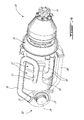
- each unit 12 is a Wankel engine.
- a Wankel engine Referring to Fig. 2 , an exemplary embodiment of a Wankel engine is shown; it is understood that the configuration of the unit(s) 12 used in the compound cycle engine 10, e.g. placement of ports, number and placement of seals, etc., may vary from that of the embodiment shown; each unit 12 may be defined by a rotary engine other than a Wankel engine.
- each unit 12 comprises a housing 32 defining a rotor cavity with a profile defining two lobes, which is preferably an epitrochoid.
- a rotor 34 is received within the rotor cavity.
- the rotor defines three circumferentially-spaced apex portions 36, and a generally triangular profile with outwardly arched sides.
- the apex portions 36 are in sealing engagement with the inner surface of a peripheral wall 38 of the housing 32 to form three working chambers 40 between the rotor 34 and the housing 32.
- the rotor 34 is engaged to an eccentric portion 42 of the output shaft 16 to perform orbital revolutions within the stator cavity.
- the output shaft 16 performs three rotations for each orbital revolution of the rotor 34.
- the geometrical axis 44 of the rotor 34 is offset from and parallel to the axis 46 of the housing 32.
- each chamber 40 varies in volume and moves around the stator cavity to undergo the four phases of intake, compression, expansion and exhaust.
- An intake port 48 is provided through the peripheral wall 38 for admitting compressed air into one of the working chambers 40.
- An exhaust port 50 is also provided through the peripheral wall 38 for discharge of the exhaust gases from the working chambers 40.
- Passages 52 for a spark plug or other ignition mechanism, as well as for one or more fuel injectors (not shown) are also provided through the peripheral wall 38.
- the intake port 48, the exhaust port 50 and/or the passages 52 may be provided through an end or side wall 54 of the housing.
- the working chambers 40 are sealed, for example by spring-loaded apex seals 56 extending from the rotor 34 to engage the peripheral wall 38, and spring-loaded face or gas seals 58 and end or corner seals 60 extending from the rotor 34 to engage the end walls 54.
- the rotor 34 also includes at least one spring-loaded oil seal ring 62 biased against the end wall 54 around the bearing for the rotor 34 on the shaft eccentric portion 42.
- Each Wankel engine provides an exhaust flow in the form of a relatively long exhaust pulse; for example, in a particular embodiment, each Wankel engine has one explosion per 360° of rotation of the output shaft, with the exhaust port remaining open for about 270° of that rotation, thus providing for a pulse duty cycle of about 75%.
- a piston of a reciprocating 4-stroke piston engine typically has one explosion per 720° of rotation of the output shaft with the exhaust port remaining open for about 180° of that rotation, thus providing a pulse duty cycle of 25%.
- the relatively long exhaust pulse of the Wankel engine may facilitate driving of the velocity power turbine 26.
- the inventors have found that in prior art compound engines including one or more rotary engines where the power turbine is a pressure turbine located downstream of the turbocharger turbine, and where each rotary engine has equal volumetric expansion and compression ratios, the relatively high volumetric compression ratio of the rotary engine(s) typically results in a relatively low possible pressure ratio for the compressor of the turbocharger (P C ), as limited by the peak pressure capability of the rotary engine(s). As such, the pressure ratio across the turbines (P PT P TT ) is limited, which limits the power available for the power turbine.
- the volumetric compression ratio of each rotary engine is smaller than its expansion ratio.
- the lower volumetric compression ratio typically results in a larger possible pressure ratio for the compressor of the turbocharger (P C ), which in turn increases the pressure ratio across the turbines (P PT P TT ).
- the lower volumetric compression ratio usually leads to an inlet to outlet pressure ratio P R of the rotary engine(s) which is reduced, which may increase back pressure and thermal loads on the rotary engine(s) because of the increased difficulty in purging the exhaust gases.
- Such a configuration also generally provides for a low compression on the rotary engine on start-up before the turbocharger is running, which may limit performances of the compound cycle engine.
- the pressure ratio P PT across the power turbine 26 is about 1 since it is a velocity turbine.
- a same pressure ratio for the compressor P C (to comply with the peak pressure capability) and a same inlet to outlet pressure ratio of the rotary unit(s) P R (to minimize backpressure and thermal loading on each rotary unit) allow for the pressure ratio P TT available for the turbine 22 of the turbocharger 18 to be greater than with a compound cycle engine in which the power turbine is a pressure turbine, i.e. with a pressure ratio P PT greater than 1.
- the use of a velocity turbine as the power turbine 26 may allow for an increase of the power available to the turbo compounding.
- the volumetric compression ratio of the rotary unit(s) 12 does not need to be reduced to achieve this increase in power available for the turbine 22 of the turbocharger 18.
- the volumetric efficiency of each rotary unit may be maximized and its thermal loads minimized, and the performances of the compound cycle engine 10 at start-up are not compromised by the increase of available power.
- a velocity turbine as the power turbine 26 eliminates the need for the large volume exhaust collector typically required between the rotary engine(s) and a pressure power turbine. This allows for the power turbine 26 to be located upstream of the compound turbine 22 instead of downstream thereof.
- each rotary unit 12 is a Wankel engine with a volumetric compression ratio of from 6:1 to 8:1.
- the power recovery of the velocity turbine 26 may be maximized by having the exhaust gas temperatures at the material limit, and as such is suitable for such relatively low volumetric compression ratios, which may help increase the power density of the Wankel engine and may also improve combustion at high speed and of heavy fuel.
- a compound cycle engine 10 according to a particular embodiment is schematically shown.
- two rotary units 12 in the form of Wankel engines are included, with the two eccentric portions 42 of the output shaft 16 being angularly offset at 180° from one another for balancing of the compound cycle engine 10.
- more or less rotary engines may be provided.
- the rotor blades 64 of the velocity power turbine 26 extend across an annular flowpath 66.
- the rotor of the power turbine 26 is an axial rotor and the flowpath 66 extends axially.
- a respective exhaust pipe 68 extends from the exhaust port 50 (see also Fig. 2 ) of each unit 12 to the flowpath 66, upstream of the rotor blades 64.
- the exhaust pipes 68 extend independently from one another, and their length are minimized to maximize use of the exhaust pulse kinetic energy to drive the power turbine 26.
- the flowpath 66 and/or the outlet of each exhaust pipe 68 are shaped to direct the exhaust pulses onto the blades 64 to allow the exhaust pulses to drive rotation of the rotor of the power turbine 26.
- each exhaust pipe 68 communicates with the flowpath 66 at a different location around the circumference of the power turbine 26.
- a pipe 70 extends from an outlet of the compressor 20, and splits into two inlet pipes 72, each connected to the intake port 48 (see also Fig. 2 ) of the respective rotary unit 12.
- the compressor 20 includes a single radial impeller 74.
- the compressor 20 may include one or more rotors, with radial, axial or mixed flow blades.
- the transmission 28 of the power turbine 26 includes a sun gear 76 attached on the shaft of the rotor of the power turbine 26, and an array of planet gears 78 meshed with the sun gear 76.
- the planet gears 78 are mounted on a rotating carrier which is drivingly engaged to the output shaft 16.
- the planet gears 78 are meshed with a stationary ring gear 79.
- the planet gears 78 are mounted on a stationary carrier, and are meshed with a ring gear drivingly engaged to the output shaft 16.
- the speed reduction ratio of the transmission 28 may be selected to optimize operation of the velocity power turbine 26 and of the rotary units 12.
- a turbine pipe 80 extends from the flowpath 66 downstream of the rotor blades 64 to the inlet of the turbocharger turbine 22.
- the turbocharger turbine 22 includes a single radial impeller 82.
- the turbocharger turbine 22 may include one or more rotors, with radial, axial or mixed flow blades.
- the turbocharger shaft 24 extends along a different axis than that of the output shaft 16. In the particular embodiment shown in Fig. 4 , the turbocharger shaft 24 extends transverse to the output shaft 16. The turbocharger shaft 24 may additionally be connected to a different load than that of the output shaft 16, through a gearbox if necessary.
- a compound cycle engine 110 according to another embodiment is schematically shown, where elements similar to those of the previously described compound cycle engine 10 are identified by the same reference numerals and will not be further described therein.
- the turbocharger 118 is defined coaxially with the output shaft 16.
- the compressor 120 is connected to the output shaft 16 through an appropriate type of transmission 128, for example a planetary or star gear system.
- the pressure turbine 122 of the turbocharger 118 is connected to the velocity power turbine 26 to rotate together therewith, or else connected to the output shaft 16 through an appropriate type of transmission (not shown).
- turbocharger and rotary unit(s) are coaxial, but the output shaft and turbocharger shaft rotate independently from one another, for example with the output shaft being hollow and surrounding the turbocharger shaft which extends therethrough.
- variable geometry elements such as inlet guide vanes, blow-off valves, waste gates, variable turbine nozzles, etc. may be used to obtain desired system operability.
- the velocity power turbine 26 may be mounted in an offset manner rather than co-axially with the rotary units 12.
- the power turbine 26 may be drivingly engaged to the output shaft through an angular, for example perpendicular, transmission system, for example including a gearbox and a tower shaft.
Applications Claiming Priority (1)
| Application Number | Priority Date | Filing Date | Title |
|---|---|---|---|
| US13/554,517 US9512721B2 (en) | 2012-07-20 | 2012-07-20 | Compound cycle engine |
Publications (3)
| Publication Number | Publication Date |
|---|---|
| EP2687675A2 true EP2687675A2 (fr) | 2014-01-22 |
| EP2687675A3 EP2687675A3 (fr) | 2014-09-10 |
| EP2687675B1 EP2687675B1 (fr) | 2016-04-27 |
Family
ID=48803446
Family Applications (1)
| Application Number | Title | Priority Date | Filing Date |
|---|---|---|---|
| EP13177313.7A Active EP2687675B1 (fr) | 2012-07-20 | 2013-07-19 | Moteur à cycle composé |
Country Status (5)
| Country | Link |
|---|---|
| US (3) | US9512721B2 (fr) |
| EP (1) | EP2687675B1 (fr) |
| CA (1) | CA2821444C (fr) |
| ES (1) | ES2584404T3 (fr) |
| PL (1) | PL2687675T3 (fr) |
Cited By (22)
| Publication number | Priority date | Publication date | Assignee | Title |
|---|---|---|---|---|
| EP3059417A1 (fr) * | 2015-02-20 | 2016-08-24 | Pratt & Whitney Canada Corp. | Ensemble moteur à compresseur et de turbine modulaire |
| EP3059421A1 (fr) * | 2015-02-20 | 2016-08-24 | Pratt & Whitney Canada Corp. | Ensemble moteur combiné avec admission commune |
| EP3059414A1 (fr) * | 2015-02-20 | 2016-08-24 | Pratt & Whitney Canada Corp. | Ensemble d'admission de moteur avec soupape de sélection |
| EP3059416A1 (fr) * | 2015-02-20 | 2016-08-24 | Pratt & Whitney Canada Corp. | Ensemble moteur composé avec l'arbre de turbine, l'arbre de moteur et le conduit d'admission décalés |
| EP3059418A1 (fr) * | 2015-02-20 | 2016-08-24 | Pratt & Whitney Canada Corp. | Ensemble moteur composé avec une zone pare-feu délimitée |
| EP3064743A1 (fr) * | 2015-02-20 | 2016-09-07 | Pratt & Whitney Canada Corp. | Ensemble moteur composé avec compresseur et de turbine en porte-à-faux |
| EP3106643A1 (fr) * | 2015-06-16 | 2016-12-21 | Pratt & Whitney Canada Corp. | Moteur à cycle composé |
| EP3106644A1 (fr) * | 2015-06-16 | 2016-12-21 | Pratt & Whitney Canada Corp. | Moteur à cycle composé |
| EP3106609A1 (fr) * | 2015-06-16 | 2016-12-21 | Pratt & Whitney Canada Corp. | Ensemble moteur composé avec buse de tuyau d'échappement |
| EP3109161A1 (fr) * | 2015-06-25 | 2016-12-28 | Pratt & Whitney Canada Corp. | Ensemble moteur composé à entraînement direct de générateur |
| EP3109166A1 (fr) * | 2015-06-25 | 2016-12-28 | Pratt & Whitney Canada Corp. | Ensemble moteur combiné avec de l'air de prélèvement |
| CN107407207A (zh) * | 2015-02-20 | 2017-11-28 | 普拉特 - 惠特尼加拿大公司 | 具有同轴压缩机和偏移涡轮机部段的复合发动机组件 |
| US9856789B2 (en) | 2012-07-20 | 2018-01-02 | Pratt & Whitney Canada Corp. | Compound cycle engine |
| US9896998B2 (en) | 2015-02-20 | 2018-02-20 | Pratt & Whitney Canada Corp. | Compound engine assembly with modulated flow |
| US9926843B2 (en) | 2012-07-20 | 2018-03-27 | Pratt & Whitney Canada Corp. | Compound cycle engine |
| US10107195B2 (en) | 2012-07-20 | 2018-10-23 | Pratt & Whitney Canada Corp. | Compound cycle engine |
| US10196971B2 (en) | 2012-07-20 | 2019-02-05 | Pratt & Whitney Canada Corp. | Compound cycle engine |
| US10428734B2 (en) | 2015-02-20 | 2019-10-01 | Pratt & Whitney Canada Corp. | Compound engine assembly with inlet lip anti-icing |
| US10533492B2 (en) | 2015-02-20 | 2020-01-14 | Pratt & Whitney Canada Corp. | Compound engine assembly with mount cage |
| US10533500B2 (en) | 2015-02-20 | 2020-01-14 | Pratt & Whitney Canada Corp. | Compound engine assembly with mount cage |
| US10696417B2 (en) | 2015-06-25 | 2020-06-30 | Pratt & Whitney Canada Corp. | Auxiliary power unit with excess air recovery |
| US10710738B2 (en) | 2015-06-25 | 2020-07-14 | Pratt & Whitney Canada Corp. | Auxiliary power unit with intercooler |
Families Citing this family (15)
| Publication number | Priority date | Publication date | Assignee | Title |
|---|---|---|---|---|
| US10280830B2 (en) | 2013-03-08 | 2019-05-07 | Pratt & Whitney Canada Corp. | System for pilot subchamber temperature control |
| US9200563B2 (en) | 2013-03-12 | 2015-12-01 | Pratt & Whitney Canada Corp. | Internal combustion engine with common rail pilot and main injection |
| US9399947B2 (en) | 2013-03-12 | 2016-07-26 | Pratt & Whitney Canada Corp. | Internal combustion engine with pilot and main injection |
| US9181863B2 (en) | 2013-03-13 | 2015-11-10 | Pratt & Whitney Canada Corp. | Internal combustion engine with port communication |
| CN104775911B (zh) * | 2014-02-12 | 2017-05-10 | 摩尔动力(北京)技术股份有限公司 | 叶轮变界组合发动机 |
| US10196923B2 (en) | 2014-08-28 | 2019-02-05 | Pratt & Whitney Canada Corp. | Operation of aircraft engines during transient conditions |
| JP2016061275A (ja) * | 2014-09-22 | 2016-04-25 | マツダ株式会社 | 車両搭載用ロータリピストンエンジン |
| US10662903B2 (en) * | 2015-02-27 | 2020-05-26 | Avl Powertrain Engineering, Inc. | Waste heat recovery and boost systems including variable drive mechanisms |
| US10267191B2 (en) * | 2015-08-07 | 2019-04-23 | Pratt & Whitney Canada Corp. | Turboprop engine assembly with combined engine and cooling exhaust |
| US10240522B2 (en) | 2015-08-07 | 2019-03-26 | Pratt & Whitney Canada Corp. | Auxiliary power unit with combined cooling of generator |
| US10253726B2 (en) | 2015-08-07 | 2019-04-09 | Pratt & Whitney Canada Corp. | Engine assembly with combined engine and cooling exhaust |
| US10253687B2 (en) * | 2015-08-07 | 2019-04-09 | Pratt & Whitney Canada Corp. | Auxiliary power unit with electrically driven compressor |
| US10082029B2 (en) * | 2016-07-08 | 2018-09-25 | Pratt & Whitney Canada Corp. | Internal combustion engine with rotor having offset peripheral surface |
| US11365706B2 (en) | 2020-11-04 | 2022-06-21 | William Todd Hodges | Turbine engine system utilizing an augmented combustion module |
| CN113294228B (zh) * | 2021-05-17 | 2022-05-17 | 天津大学 | 一种挥发性有机废气处理系统 |
Citations (1)
| Publication number | Priority date | Publication date | Assignee | Title |
|---|---|---|---|---|
| US7775044B2 (en) | 2003-02-24 | 2010-08-17 | Pratt & Whitney Canada Corp. | Low volumetric compression ratio integrated turbo-compound rotary engine |
Family Cites Families (51)
| Publication number | Priority date | Publication date | Assignee | Title |
|---|---|---|---|---|
| CH202931A (de) * | 1937-03-25 | 1939-02-15 | Maschf Augsburg Nuernberg Ag | Brennkraftmaschine mit Spülung und Aufladung, insbesondere für Höhenflug. |
| US2748564A (en) | 1951-03-16 | 1956-06-05 | Snecma | Intermittent combustion gas turbine engine |
| US3672160A (en) | 1971-05-20 | 1972-06-27 | Dae Sik Kim | System for producing substantially pollution-free hot gas under pressure for use in a prime mover |
| DE2233014A1 (de) | 1972-07-05 | 1974-01-17 | Wankel Gmbh | Aufladbare rotationskolbenbrennkraftmaschine |
| US3993029A (en) | 1972-07-05 | 1976-11-23 | Wankel Gmbh | Method of operating a compound supercharged rotary piston engine |
| US4100742A (en) * | 1976-12-09 | 1978-07-18 | The United States Of America As Represented By The Secretary Of The Army | Turbocompound engine with turbocharger control |
| US4135485A (en) | 1977-06-21 | 1979-01-23 | Curtiss-Wright Corporation | Split-multi-unit rotary combustion engine |
| US4221192A (en) * | 1978-06-26 | 1980-09-09 | Cummins Engine Company, Inc. | Fuel injector and common rail fuel supply system |
| US4435121A (en) | 1979-09-27 | 1984-03-06 | Solar Turbines Incorporated | Turbines |
| US4403928A (en) * | 1981-03-30 | 1983-09-13 | Curtiss-Wright Corporation | Multi-unit rotary mechanism |
| JPS63502768A (ja) * | 1986-01-16 | 1988-10-13 | リ−ズ,ジョン・アンソニ−・ジェネス | 原動機及びそれらの作動サイクル |
| US4742683A (en) | 1986-08-18 | 1988-05-10 | Teledyne Industries, Inc. | Turbocompound engine |
| US4815282A (en) | 1987-02-24 | 1989-03-28 | Teledyne Industries, Inc. | Turbocharged compund cycle ducted fan engine system |
| GB2207191B (en) | 1987-07-06 | 1992-03-04 | Gen Electric | Gas turbine engine |
| US4973233A (en) * | 1987-09-11 | 1990-11-27 | Mazda Motor Corporation | Four-rotor type rotary piston engine |
| SU1686202A1 (ru) | 1989-03-27 | 1991-10-23 | Новосибирский сельскохозяйственный институт | Двигатель внутреннего сгорани |
| GB2301632B (en) | 1995-03-18 | 1998-06-24 | Rolls Royce Plc | Aircraft compound cycle propulsion engine |
| DE19701020A1 (de) | 1997-01-14 | 1998-07-23 | Siemens Ag | Dampfturbine |
| DE10049912A1 (de) | 2000-10-10 | 2002-04-11 | Daimler Chrysler Ag | Brennkraftmaschine mit Abgasturbolader und Compound-Nutzturbine |
| FR2829528B1 (fr) | 2001-09-07 | 2004-02-27 | Bernard Gilbert Macarez | Pulsomoteur-turbomoteur a impulsion-turbine a gaz a chambre de combustion impulsionnelle et a detente de bouffees |
| US7201121B2 (en) | 2002-02-04 | 2007-04-10 | Caterpillar Inc | Combustion engine including fluidically-driven engine valve actuator |
| CA2516720C (fr) | 2003-02-24 | 2012-04-24 | Pratt & Whitney Canada Corp. | Moteur rotatif turbo-combine integre a faible taux de compression volumetrique |
| US20040177837A1 (en) | 2003-03-11 | 2004-09-16 | Bryant Clyde C. | Cold air super-charged internal combustion engine, working cycle & method |
| ITTV20030089A1 (it) * | 2003-06-19 | 2003-09-17 | Orlando Canal | Meccanismo per gas-dinamica azione volumetrica alterno rotativa a 60 grado, "gavara-60", per uso generale e particolarmente per motori endotermic |
| US7100546B2 (en) | 2004-09-21 | 2006-09-05 | Mark Sorochkin | Crankshaftless internal combustion engine |
| US7182075B2 (en) * | 2004-12-07 | 2007-02-27 | Honeywell International Inc. | EGR system |
| DE102006014934A1 (de) | 2006-03-31 | 2007-10-04 | Daimlerchrysler Ag | Brennkraftmaschine mit zwei in Reihe geschalteten Abgasturboladern |
| US7640745B2 (en) | 2007-01-15 | 2010-01-05 | Concepts Eti, Inc. | High-pressure fluid compression system utilizing cascading effluent energy recovery |
| US7753036B2 (en) | 2007-07-02 | 2010-07-13 | United Technologies Corporation | Compound cycle rotary engine |
| DE102008039086A1 (de) | 2008-08-21 | 2010-02-25 | Daimler Ag | Abgasturbolader für eine Brennkraftmaschine eines Kraftfahrzeugs |
| FR2944060B1 (fr) * | 2009-04-06 | 2013-07-19 | Turbomeca | Systeme d'air secondaire pour compresseur centrifuge ou mixte |
| US8640459B2 (en) | 2009-10-23 | 2014-02-04 | GM Global Technology Operations LLC | Turbocharger control systems and methods for improved transient performance |
| US8695565B2 (en) | 2010-02-16 | 2014-04-15 | Sine Waves, Inc. | Co-axial rotary engine |
| US8418672B2 (en) | 2010-03-04 | 2013-04-16 | James L. Groves | High leverage rotary internal combustion engine |
| US20120227397A1 (en) | 2011-03-10 | 2012-09-13 | Willi Martin L | Gaseous fuel-powered engine system having turbo-compounding |
| PL2497902T3 (pl) | 2011-03-10 | 2017-06-30 | Uav Engines Ltd | Wirnik silnika rotacyjnego |
| US8888449B2 (en) | 2011-05-12 | 2014-11-18 | General Electric Company | System, transition conduit, and article of manufacture for delivering a fluid flow |
| EP2554820B1 (fr) | 2011-08-03 | 2016-12-14 | Ford Global Technologies, LLC | Moteur à combustion interne chargé doté de deux turbines et procédé de fonctionnement d'un tel moteur à combustion interne |
| US9255478B2 (en) | 2011-10-24 | 2016-02-09 | Hybrid Turbine Group | Reaction turbine and hybrid impulse reaction turbine |
| US8925317B2 (en) | 2012-07-16 | 2015-01-06 | General Electric Company | Engine with improved EGR system |
| US9926843B2 (en) | 2012-07-20 | 2018-03-27 | Pratt & Whitney Canada Corp. | Compound cycle engine |
| US9512721B2 (en) | 2012-07-20 | 2016-12-06 | Pratt & Whitney Canada Corp. | Compound cycle engine |
| US9194232B2 (en) | 2012-07-20 | 2015-11-24 | Pratt & Whitney Canada Corp. | Compound cycle engine |
| US9181855B2 (en) | 2013-01-31 | 2015-11-10 | Electro-Motive Diesel, Inc. | Turbocharger with axial turbine stage |
| US9181863B2 (en) | 2013-03-13 | 2015-11-10 | Pratt & Whitney Canada Corp. | Internal combustion engine with port communication |
| ITMI20132166A1 (it) | 2013-12-20 | 2015-06-21 | Fpt Ind Spa | Sistema turbo compound migliorato |
| ITMI20132165A1 (it) | 2013-12-20 | 2015-06-21 | Fpt Ind Spa | Sistema turbo compound migliorato |
| US9869240B2 (en) | 2015-02-20 | 2018-01-16 | Pratt & Whitney Canada Corp. | Compound engine assembly with cantilevered compressor and turbine |
| US9896998B2 (en) | 2015-02-20 | 2018-02-20 | Pratt & Whitney Canada Corp. | Compound engine assembly with modulated flow |
| US9932892B2 (en) | 2015-02-20 | 2018-04-03 | Pratt & Whitney Canada Corp. | Compound engine assembly with coaxial compressor and offset turbine section |
| US9759128B2 (en) | 2015-06-16 | 2017-09-12 | Pratt & Whitney Canada Corp. | Compound engine assembly with exhaust pipe nozzle |
-
2012
- 2012-07-20 US US13/554,517 patent/US9512721B2/en active Active
-
2013
- 2013-07-17 CA CA2821444A patent/CA2821444C/fr active Active
- 2013-07-19 PL PL13177313.7T patent/PL2687675T3/pl unknown
- 2013-07-19 EP EP13177313.7A patent/EP2687675B1/fr active Active
- 2013-07-19 ES ES13177313.7T patent/ES2584404T3/es active Active
-
2016
- 2016-11-09 US US15/346,864 patent/US10196971B2/en active Active
-
2018
- 2018-12-20 US US16/226,702 patent/US10920662B2/en active Active
Patent Citations (1)
| Publication number | Priority date | Publication date | Assignee | Title |
|---|---|---|---|---|
| US7775044B2 (en) | 2003-02-24 | 2010-08-17 | Pratt & Whitney Canada Corp. | Low volumetric compression ratio integrated turbo-compound rotary engine |
Cited By (50)
| Publication number | Priority date | Publication date | Assignee | Title |
|---|---|---|---|---|
| US10968824B2 (en) | 2012-07-20 | 2021-04-06 | Pratt & Whitney Canada Corp. | Compound cycle engine |
| US10196971B2 (en) | 2012-07-20 | 2019-02-05 | Pratt & Whitney Canada Corp. | Compound cycle engine |
| US10107195B2 (en) | 2012-07-20 | 2018-10-23 | Pratt & Whitney Canada Corp. | Compound cycle engine |
| US9926843B2 (en) | 2012-07-20 | 2018-03-27 | Pratt & Whitney Canada Corp. | Compound cycle engine |
| US9856789B2 (en) | 2012-07-20 | 2018-01-02 | Pratt & Whitney Canada Corp. | Compound cycle engine |
| US10920662B2 (en) | 2012-07-20 | 2021-02-16 | Pratt & Whitney Canada Corp. | Compound cycle engine |
| CN107407207A (zh) * | 2015-02-20 | 2017-11-28 | 普拉特 - 惠特尼加拿大公司 | 具有同轴压缩机和偏移涡轮机部段的复合发动机组件 |
| US9896998B2 (en) | 2015-02-20 | 2018-02-20 | Pratt & Whitney Canada Corp. | Compound engine assembly with modulated flow |
| US10883414B2 (en) | 2015-02-20 | 2021-01-05 | Pratt & Whitney Canada Corp. | Engine intake assembly with selector valve |
| US10677154B2 (en) | 2015-02-20 | 2020-06-09 | Pratt & Whitney Canada Corp. | Compound engine assembly with offset turbine shaft, engine shaft and inlet duct |
| US10598086B2 (en) | 2015-02-20 | 2020-03-24 | Pratt & Whitney Canada Corp. | Compound engine assembly with cantilevered compressor and turbine |
| EP3059417A1 (fr) * | 2015-02-20 | 2016-08-24 | Pratt & Whitney Canada Corp. | Ensemble moteur à compresseur et de turbine modulaire |
| CN107407207B (zh) * | 2015-02-20 | 2020-03-20 | 普拉特-惠特尼加拿大公司 | 具有同轴压缩机和偏移涡轮机部段的复合发动机组件 |
| US9797297B2 (en) | 2015-02-20 | 2017-10-24 | Pratt & Whitney Canada Corp. | Compound engine assembly with common inlet |
| US10428734B2 (en) | 2015-02-20 | 2019-10-01 | Pratt & Whitney Canada Corp. | Compound engine assembly with inlet lip anti-icing |
| CN107532519A (zh) * | 2015-02-20 | 2018-01-02 | 普拉特 - 惠特尼加拿大公司 | 具有偏移涡轮机轴、发动机轴和入口导管的复合发动机组件 |
| EP3059418A1 (fr) * | 2015-02-20 | 2016-08-24 | Pratt & Whitney Canada Corp. | Ensemble moteur composé avec une zone pare-feu délimitée |
| US9869240B2 (en) | 2015-02-20 | 2018-01-16 | Pratt & Whitney Canada Corp. | Compound engine assembly with cantilevered compressor and turbine |
| US9879591B2 (en) | 2015-02-20 | 2018-01-30 | Pratt & Whitney Canada Corp. | Engine intake assembly with selector valve |
| EP3064743A1 (fr) * | 2015-02-20 | 2016-09-07 | Pratt & Whitney Canada Corp. | Ensemble moteur composé avec compresseur et de turbine en porte-à-faux |
| EP3059416A1 (fr) * | 2015-02-20 | 2016-08-24 | Pratt & Whitney Canada Corp. | Ensemble moteur composé avec l'arbre de turbine, l'arbre de moteur et le conduit d'admission décalés |
| US9932892B2 (en) | 2015-02-20 | 2018-04-03 | Pratt & Whitney Canada Corp. | Compound engine assembly with coaxial compressor and offset turbine section |
| CN107532519B (zh) * | 2015-02-20 | 2020-03-20 | 普拉特-惠特尼加拿大公司 | 具有偏移涡轮机轴、发动机轴和入口导管的复合发动机组件 |
| US10533500B2 (en) | 2015-02-20 | 2020-01-14 | Pratt & Whitney Canada Corp. | Compound engine assembly with mount cage |
| US10533492B2 (en) | 2015-02-20 | 2020-01-14 | Pratt & Whitney Canada Corp. | Compound engine assembly with mount cage |
| US10533489B2 (en) | 2015-02-20 | 2020-01-14 | Pratt & Whitney Canada Corp. | Compound engine assembly with common inlet |
| EP3059414A1 (fr) * | 2015-02-20 | 2016-08-24 | Pratt & Whitney Canada Corp. | Ensemble d'admission de moteur avec soupape de sélection |
| EP3059421A1 (fr) * | 2015-02-20 | 2016-08-24 | Pratt & Whitney Canada Corp. | Ensemble moteur combiné avec admission commune |
| US10371060B2 (en) | 2015-02-20 | 2019-08-06 | Pratt & Whitney Canada Corp. | Compound engine assembly with confined fire zone |
| US10533487B2 (en) | 2015-02-20 | 2020-01-14 | Pratt & Whitney Canada Corp. | Engine intake assembly with selector valve |
| US10408123B2 (en) | 2015-02-20 | 2019-09-10 | Pratt & Whitney Canada Corp. | Engine assembly with modular compressor and turbine |
| US9759128B2 (en) | 2015-06-16 | 2017-09-12 | Pratt & Whitney Canada Corp. | Compound engine assembly with exhaust pipe nozzle |
| CN107923310B (zh) * | 2015-06-16 | 2020-03-31 | 普拉特-惠特尼加拿大公司 | 复合循环发动机 |
| US10393014B2 (en) | 2015-06-16 | 2019-08-27 | Pratt & Whitney Canada Corp. | Engine assembly with exhaust pipe nozzle |
| EP3106643A1 (fr) * | 2015-06-16 | 2016-12-21 | Pratt & Whitney Canada Corp. | Moteur à cycle composé |
| CN107923310A (zh) * | 2015-06-16 | 2018-04-17 | 普拉特 - 惠特尼加拿大公司 | 复合循环发动机 |
| CN107923309A (zh) * | 2015-06-16 | 2018-04-17 | 普拉特 - 惠特尼加拿大公司 | 复合循环发动机 |
| EP3106644A1 (fr) * | 2015-06-16 | 2016-12-21 | Pratt & Whitney Canada Corp. | Moteur à cycle composé |
| CN107923308A (zh) * | 2015-06-16 | 2018-04-17 | 普拉特 - 惠特尼加拿大公司 | 具有排出管喷嘴的复合发动机组件 |
| EP3106609A1 (fr) * | 2015-06-16 | 2016-12-21 | Pratt & Whitney Canada Corp. | Ensemble moteur composé avec buse de tuyau d'échappement |
| CN107923308B (zh) * | 2015-06-16 | 2020-06-12 | 普拉特-惠特尼加拿大公司 | 具有排出管喷嘴的复合发动机组件 |
| EP3109166A1 (fr) * | 2015-06-25 | 2016-12-28 | Pratt & Whitney Canada Corp. | Ensemble moteur combiné avec de l'air de prélèvement |
| EP3109161A1 (fr) * | 2015-06-25 | 2016-12-28 | Pratt & Whitney Canada Corp. | Ensemble moteur composé à entraînement direct de générateur |
| US10501200B2 (en) | 2015-06-25 | 2019-12-10 | Pratt & Whitney Canada Corp. | Engine assembly for an auxiliary power unit |
| US10696417B2 (en) | 2015-06-25 | 2020-06-30 | Pratt & Whitney Canada Corp. | Auxiliary power unit with excess air recovery |
| US10710738B2 (en) | 2015-06-25 | 2020-07-14 | Pratt & Whitney Canada Corp. | Auxiliary power unit with intercooler |
| US9771165B2 (en) | 2015-06-25 | 2017-09-26 | Pratt & Whitney Canada Corp. | Compound engine assembly with direct drive of generator |
| US10590842B2 (en) | 2015-06-25 | 2020-03-17 | Pratt & Whitney Canada Corp. | Compound engine assembly with bleed air |
| US9994332B2 (en) | 2015-06-25 | 2018-06-12 | Pratt & Whitney Canada Corp. | Engine assembly with direct drive of generator |
| US11584539B2 (en) | 2015-06-25 | 2023-02-21 | Pratt & Whitney Canada Corp. | Auxiliary power unit with intercooler |
Also Published As
| Publication number | Publication date |
|---|---|
| ES2584404T3 (es) | 2016-09-27 |
| EP2687675A3 (fr) | 2014-09-10 |
| US20140020380A1 (en) | 2014-01-23 |
| EP2687675B1 (fr) | 2016-04-27 |
| US10196971B2 (en) | 2019-02-05 |
| PL2687675T3 (pl) | 2016-12-30 |
| CA2821444A1 (fr) | 2014-01-20 |
| US9512721B2 (en) | 2016-12-06 |
| US10920662B2 (en) | 2021-02-16 |
| CA2821444C (fr) | 2020-06-23 |
| US20170051666A1 (en) | 2017-02-23 |
| US20190128177A1 (en) | 2019-05-02 |
Similar Documents
| Publication | Publication Date | Title |
|---|---|---|
| US10920662B2 (en) | Compound cycle engine | |
| US10968824B2 (en) | Compound cycle engine | |
| EP2687676B1 (fr) | Moteur à cycle composé | |
| US9926843B2 (en) | Compound cycle engine | |
| CA2933112C (fr) | Moteur a cycle combine | |
| US10393014B2 (en) | Engine assembly with exhaust pipe nozzle | |
| EP3199754B1 (fr) | Ensemble d'aube directrice d'entrée | |
| EP3106644B1 (fr) | Moteur à cycle composé |
Legal Events
| Date | Code | Title | Description |
|---|---|---|---|
| PUAI | Public reference made under article 153(3) epc to a published international application that has entered the european phase |
Free format text: ORIGINAL CODE: 0009012 |
|
| AK | Designated contracting states |
Kind code of ref document: A2 Designated state(s): AL AT BE BG CH CY CZ DE DK EE ES FI FR GB GR HR HU IE IS IT LI LT LU LV MC MK MT NL NO PL PT RO RS SE SI SK SM TR |
|
| AX | Request for extension of the european patent |
Extension state: BA ME |
|
| PUAL | Search report despatched |
Free format text: ORIGINAL CODE: 0009013 |
|
| AK | Designated contracting states |
Kind code of ref document: A3 Designated state(s): AL AT BE BG CH CY CZ DE DK EE ES FI FR GB GR HR HU IE IS IT LI LT LU LV MC MK MT NL NO PL PT RO RS SE SI SK SM TR |
|
| AX | Request for extension of the european patent |
Extension state: BA ME |
|
| RIC1 | Information provided on ipc code assigned before grant |
Ipc: F02C 6/12 20060101ALI20140804BHEP Ipc: F01C 1/22 20060101AFI20140804BHEP Ipc: F01C 11/00 20060101ALI20140804BHEP |
|
| 17P | Request for examination filed |
Effective date: 20150305 |
|
| RBV | Designated contracting states (corrected) |
Designated state(s): AL AT BE BG CH CY CZ DE DK EE ES FI FR GB GR HR HU IE IS IT LI LT LU LV MC MK MT NL NO PL PT RO RS SE SI SK SM TR |
|
| GRAP | Despatch of communication of intention to grant a patent |
Free format text: ORIGINAL CODE: EPIDOSNIGR1 |
|
| RIC1 | Information provided on ipc code assigned before grant |
Ipc: F01C 1/22 20060101AFI20150618BHEP Ipc: F02C 6/12 20060101ALI20150618BHEP Ipc: F02C 6/20 20060101ALI20150618BHEP Ipc: F01C 11/00 20060101ALI20150618BHEP |
|
| INTG | Intention to grant announced |
Effective date: 20150710 |
|
| INTG | Intention to grant announced |
Effective date: 20151207 |
|
| INTG | Intention to grant announced |
Effective date: 20160204 |
|
| GRAS | Grant fee paid |
Free format text: ORIGINAL CODE: EPIDOSNIGR3 |
|
| GRAA | (expected) grant |
Free format text: ORIGINAL CODE: 0009210 |
|
| AK | Designated contracting states |
Kind code of ref document: B1 Designated state(s): AL AT BE BG CH CY CZ DE DK EE ES FI FR GB GR HR HU IE IS IT LI LT LU LV MC MK MT NL NO PL PT RO RS SE SI SK SM TR |
|
| REG | Reference to a national code |
Ref country code: GB Ref legal event code: FG4D |
|
| REG | Reference to a national code |
Ref country code: CH Ref legal event code: EP |
|
| REG | Reference to a national code |
Ref country code: AT Ref legal event code: REF Ref document number: 795037 Country of ref document: AT Kind code of ref document: T Effective date: 20160515 |
|
| REG | Reference to a national code |
Ref country code: IE Ref legal event code: FG4D |
|
| REG | Reference to a national code |
Ref country code: DE Ref legal event code: R096 Ref document number: 602013006896 Country of ref document: DE |
|
| REG | Reference to a national code |
Ref country code: LT Ref legal event code: MG4D |
|
| REG | Reference to a national code |
Ref country code: NL Ref legal event code: MP Effective date: 20160427 |
|
| REG | Reference to a national code |
Ref country code: FR Ref legal event code: PLFP Year of fee payment: 4 |
|
| REG | Reference to a national code |
Ref country code: ES Ref legal event code: FG2A Ref document number: 2584404 Country of ref document: ES Kind code of ref document: T3 Effective date: 20160927 |
|
| PG25 | Lapsed in a contracting state [announced via postgrant information from national office to epo] |
Ref country code: NL Free format text: LAPSE BECAUSE OF FAILURE TO SUBMIT A TRANSLATION OF THE DESCRIPTION OR TO PAY THE FEE WITHIN THE PRESCRIBED TIME-LIMIT Effective date: 20160427 |
|
| PG25 | Lapsed in a contracting state [announced via postgrant information from national office to epo] |
Ref country code: FI Free format text: LAPSE BECAUSE OF FAILURE TO SUBMIT A TRANSLATION OF THE DESCRIPTION OR TO PAY THE FEE WITHIN THE PRESCRIBED TIME-LIMIT Effective date: 20160427 Ref country code: NO Free format text: LAPSE BECAUSE OF FAILURE TO SUBMIT A TRANSLATION OF THE DESCRIPTION OR TO PAY THE FEE WITHIN THE PRESCRIBED TIME-LIMIT Effective date: 20160727 Ref country code: LT Free format text: LAPSE BECAUSE OF FAILURE TO SUBMIT A TRANSLATION OF THE DESCRIPTION OR TO PAY THE FEE WITHIN THE PRESCRIBED TIME-LIMIT Effective date: 20160427 |
|
| PG25 | Lapsed in a contracting state [announced via postgrant information from national office to epo] |
Ref country code: GR Free format text: LAPSE BECAUSE OF FAILURE TO SUBMIT A TRANSLATION OF THE DESCRIPTION OR TO PAY THE FEE WITHIN THE PRESCRIBED TIME-LIMIT Effective date: 20160728 Ref country code: SE Free format text: LAPSE BECAUSE OF FAILURE TO SUBMIT A TRANSLATION OF THE DESCRIPTION OR TO PAY THE FEE WITHIN THE PRESCRIBED TIME-LIMIT Effective date: 20160427 Ref country code: LV Free format text: LAPSE BECAUSE OF FAILURE TO SUBMIT A TRANSLATION OF THE DESCRIPTION OR TO PAY THE FEE WITHIN THE PRESCRIBED TIME-LIMIT Effective date: 20160427 Ref country code: RS Free format text: LAPSE BECAUSE OF FAILURE TO SUBMIT A TRANSLATION OF THE DESCRIPTION OR TO PAY THE FEE WITHIN THE PRESCRIBED TIME-LIMIT Effective date: 20160427 Ref country code: HR Free format text: LAPSE BECAUSE OF FAILURE TO SUBMIT A TRANSLATION OF THE DESCRIPTION OR TO PAY THE FEE WITHIN THE PRESCRIBED TIME-LIMIT Effective date: 20160427 Ref country code: PT Free format text: LAPSE BECAUSE OF FAILURE TO SUBMIT A TRANSLATION OF THE DESCRIPTION OR TO PAY THE FEE WITHIN THE PRESCRIBED TIME-LIMIT Effective date: 20160829 |
|
| PG25 | Lapsed in a contracting state [announced via postgrant information from national office to epo] |
Ref country code: BE Free format text: LAPSE BECAUSE OF FAILURE TO SUBMIT A TRANSLATION OF THE DESCRIPTION OR TO PAY THE FEE WITHIN THE PRESCRIBED TIME-LIMIT Effective date: 20160427 |
|
| REG | Reference to a national code |
Ref country code: DE Ref legal event code: R097 Ref document number: 602013006896 Country of ref document: DE |
|
| PG25 | Lapsed in a contracting state [announced via postgrant information from national office to epo] |
Ref country code: EE Free format text: LAPSE BECAUSE OF FAILURE TO SUBMIT A TRANSLATION OF THE DESCRIPTION OR TO PAY THE FEE WITHIN THE PRESCRIBED TIME-LIMIT Effective date: 20160427 Ref country code: DK Free format text: LAPSE BECAUSE OF FAILURE TO SUBMIT A TRANSLATION OF THE DESCRIPTION OR TO PAY THE FEE WITHIN THE PRESCRIBED TIME-LIMIT Effective date: 20160427 Ref country code: RO Free format text: LAPSE BECAUSE OF FAILURE TO SUBMIT A TRANSLATION OF THE DESCRIPTION OR TO PAY THE FEE WITHIN THE PRESCRIBED TIME-LIMIT Effective date: 20160427 Ref country code: SK Free format text: LAPSE BECAUSE OF FAILURE TO SUBMIT A TRANSLATION OF THE DESCRIPTION OR TO PAY THE FEE WITHIN THE PRESCRIBED TIME-LIMIT Effective date: 20160427 |
|
| PG25 | Lapsed in a contracting state [announced via postgrant information from national office to epo] |
Ref country code: SM Free format text: LAPSE BECAUSE OF FAILURE TO SUBMIT A TRANSLATION OF THE DESCRIPTION OR TO PAY THE FEE WITHIN THE PRESCRIBED TIME-LIMIT Effective date: 20160427 |
|
| PLBE | No opposition filed within time limit |
Free format text: ORIGINAL CODE: 0009261 |
|
| STAA | Information on the status of an ep patent application or granted ep patent |
Free format text: STATUS: NO OPPOSITION FILED WITHIN TIME LIMIT |
|
| PG25 | Lapsed in a contracting state [announced via postgrant information from national office to epo] |
Ref country code: MC Free format text: LAPSE BECAUSE OF FAILURE TO SUBMIT A TRANSLATION OF THE DESCRIPTION OR TO PAY THE FEE WITHIN THE PRESCRIBED TIME-LIMIT Effective date: 20160427 |
|
| 26N | No opposition filed |
Effective date: 20170130 |
|
| REG | Reference to a national code |
Ref country code: IE Ref legal event code: MM4A |
|
| PG25 | Lapsed in a contracting state [announced via postgrant information from national office to epo] |
Ref country code: SI Free format text: LAPSE BECAUSE OF FAILURE TO SUBMIT A TRANSLATION OF THE DESCRIPTION OR TO PAY THE FEE WITHIN THE PRESCRIBED TIME-LIMIT Effective date: 20160427 |
|
| REG | Reference to a national code |
Ref country code: FR Ref legal event code: PLFP Year of fee payment: 5 |
|
| REG | Reference to a national code |
Ref country code: DE Ref legal event code: R082 Ref document number: 602013006896 Country of ref document: DE Representative=s name: SCHMITT-NILSON SCHRAUD WAIBEL WOHLFROM PATENTA, DE |
|
| PG25 | Lapsed in a contracting state [announced via postgrant information from national office to epo] |
Ref country code: IE Free format text: LAPSE BECAUSE OF NON-PAYMENT OF DUE FEES Effective date: 20160719 |
|
| PG25 | Lapsed in a contracting state [announced via postgrant information from national office to epo] |
Ref country code: LU Free format text: LAPSE BECAUSE OF NON-PAYMENT OF DUE FEES Effective date: 20160719 |
|
| REG | Reference to a national code |
Ref country code: AT Ref legal event code: UEP Ref document number: 795037 Country of ref document: AT Kind code of ref document: T Effective date: 20160427 |
|
| PG25 | Lapsed in a contracting state [announced via postgrant information from national office to epo] |
Ref country code: HU Free format text: LAPSE BECAUSE OF FAILURE TO SUBMIT A TRANSLATION OF THE DESCRIPTION OR TO PAY THE FEE WITHIN THE PRESCRIBED TIME-LIMIT; INVALID AB INITIO Effective date: 20130719 Ref country code: CY Free format text: LAPSE BECAUSE OF FAILURE TO SUBMIT A TRANSLATION OF THE DESCRIPTION OR TO PAY THE FEE WITHIN THE PRESCRIBED TIME-LIMIT Effective date: 20160427 |
|
| REG | Reference to a national code |
Ref country code: FR Ref legal event code: PLFP Year of fee payment: 6 |
|
| PG25 | Lapsed in a contracting state [announced via postgrant information from national office to epo] |
Ref country code: MK Free format text: LAPSE BECAUSE OF FAILURE TO SUBMIT A TRANSLATION OF THE DESCRIPTION OR TO PAY THE FEE WITHIN THE PRESCRIBED TIME-LIMIT Effective date: 20160427 Ref country code: IS Free format text: LAPSE BECAUSE OF FAILURE TO SUBMIT A TRANSLATION OF THE DESCRIPTION OR TO PAY THE FEE WITHIN THE PRESCRIBED TIME-LIMIT Effective date: 20160427 Ref country code: MT Free format text: LAPSE BECAUSE OF NON-PAYMENT OF DUE FEES Effective date: 20160731 Ref country code: TR Free format text: LAPSE BECAUSE OF FAILURE TO SUBMIT A TRANSLATION OF THE DESCRIPTION OR TO PAY THE FEE WITHIN THE PRESCRIBED TIME-LIMIT Effective date: 20160427 |
|
| PG25 | Lapsed in a contracting state [announced via postgrant information from national office to epo] |
Ref country code: BG Free format text: LAPSE BECAUSE OF FAILURE TO SUBMIT A TRANSLATION OF THE DESCRIPTION OR TO PAY THE FEE WITHIN THE PRESCRIBED TIME-LIMIT Effective date: 20160427 |
|
| PG25 | Lapsed in a contracting state [announced via postgrant information from national office to epo] |
Ref country code: AL Free format text: LAPSE BECAUSE OF FAILURE TO SUBMIT A TRANSLATION OF THE DESCRIPTION OR TO PAY THE FEE WITHIN THE PRESCRIBED TIME-LIMIT Effective date: 20160427 |
|
| P01 | Opt-out of the competence of the unified patent court (upc) registered |
Effective date: 20230530 |
|
| PGFP | Annual fee paid to national office [announced via postgrant information from national office to epo] |
Ref country code: IT Payment date: 20230620 Year of fee payment: 11 Ref country code: FR Payment date: 20230621 Year of fee payment: 11 Ref country code: CZ Payment date: 20230623 Year of fee payment: 11 |
|
| PGFP | Annual fee paid to national office [announced via postgrant information from national office to epo] |
Ref country code: PL Payment date: 20230623 Year of fee payment: 11 |
|
| PGFP | Annual fee paid to national office [announced via postgrant information from national office to epo] |
Ref country code: GB Payment date: 20230620 Year of fee payment: 11 Ref country code: ES Payment date: 20230801 Year of fee payment: 11 Ref country code: CH Payment date: 20230801 Year of fee payment: 11 Ref country code: AT Payment date: 20230622 Year of fee payment: 11 |
|
| PGFP | Annual fee paid to national office [announced via postgrant information from national office to epo] |
Ref country code: DE Payment date: 20230620 Year of fee payment: 11 |