EP3106643A1 - Moteur à cycle composé - Google Patents
Moteur à cycle composé Download PDFInfo
- Publication number
- EP3106643A1 EP3106643A1 EP16174757.1A EP16174757A EP3106643A1 EP 3106643 A1 EP3106643 A1 EP 3106643A1 EP 16174757 A EP16174757 A EP 16174757A EP 3106643 A1 EP3106643 A1 EP 3106643A1
- Authority
- EP
- European Patent Office
- Prior art keywords
- stage turbine
- turbine
- engine
- rotor
- fluid communication
- Prior art date
- Legal status (The legal status is an assumption and is not a legal conclusion. Google has not performed a legal analysis and makes no representation as to the accuracy of the status listed.)
- Ceased
Links
Images


Classifications
-
- F—MECHANICAL ENGINEERING; LIGHTING; HEATING; WEAPONS; BLASTING
- F02—COMBUSTION ENGINES; HOT-GAS OR COMBUSTION-PRODUCT ENGINE PLANTS
- F02B—INTERNAL-COMBUSTION PISTON ENGINES; COMBUSTION ENGINES IN GENERAL
- F02B41/00—Engines characterised by special means for improving conversion of heat or pressure energy into mechanical power
- F02B41/02—Engines with prolonged expansion
- F02B41/10—Engines with prolonged expansion in exhaust turbines
-
- F—MECHANICAL ENGINEERING; LIGHTING; HEATING; WEAPONS; BLASTING
- F01—MACHINES OR ENGINES IN GENERAL; ENGINE PLANTS IN GENERAL; STEAM ENGINES
- F01C—ROTARY-PISTON OR OSCILLATING-PISTON MACHINES OR ENGINES
- F01C1/00—Rotary-piston machines or engines
- F01C1/22—Rotary-piston machines or engines of internal-axis type with equidirectional movement of co-operating members at the points of engagement, or with one of the co-operating members being stationary, the inner member having more teeth or tooth- equivalents than the outer member
-
- F—MECHANICAL ENGINEERING; LIGHTING; HEATING; WEAPONS; BLASTING
- F01—MACHINES OR ENGINES IN GENERAL; ENGINE PLANTS IN GENERAL; STEAM ENGINES
- F01C—ROTARY-PISTON OR OSCILLATING-PISTON MACHINES OR ENGINES
- F01C11/00—Combinations of two or more machines or engines, each being of rotary-piston or oscillating-piston type
- F01C11/002—Combinations of two or more machines or engines, each being of rotary-piston or oscillating-piston type of similar working principle
-
- F—MECHANICAL ENGINEERING; LIGHTING; HEATING; WEAPONS; BLASTING
- F01—MACHINES OR ENGINES IN GENERAL; ENGINE PLANTS IN GENERAL; STEAM ENGINES
- F01C—ROTARY-PISTON OR OSCILLATING-PISTON MACHINES OR ENGINES
- F01C11/00—Combinations of two or more machines or engines, each being of rotary-piston or oscillating-piston type
- F01C11/006—Combinations of two or more machines or engines, each being of rotary-piston or oscillating-piston type of dissimilar working principle
- F01C11/008—Combinations of two or more machines or engines, each being of rotary-piston or oscillating-piston type of dissimilar working principle and of complementary function, e.g. internal combustion engine with supercharger
-
- F—MECHANICAL ENGINEERING; LIGHTING; HEATING; WEAPONS; BLASTING
- F01—MACHINES OR ENGINES IN GENERAL; ENGINE PLANTS IN GENERAL; STEAM ENGINES
- F01C—ROTARY-PISTON OR OSCILLATING-PISTON MACHINES OR ENGINES
- F01C20/00—Control of, monitoring of, or safety arrangements for, machines or engines
- F01C20/02—Control of, monitoring of, or safety arrangements for, machines or engines specially adapted for several machines or engines connected in series or in parallel
-
- F—MECHANICAL ENGINEERING; LIGHTING; HEATING; WEAPONS; BLASTING
- F01—MACHINES OR ENGINES IN GENERAL; ENGINE PLANTS IN GENERAL; STEAM ENGINES
- F01C—ROTARY-PISTON OR OSCILLATING-PISTON MACHINES OR ENGINES
- F01C21/00—Component parts, details or accessories not provided for in groups F01C1/00 - F01C20/00
- F01C21/007—General arrangements of parts; Frames and supporting elements
-
- F—MECHANICAL ENGINEERING; LIGHTING; HEATING; WEAPONS; BLASTING
- F02—COMBUSTION ENGINES; HOT-GAS OR COMBUSTION-PRODUCT ENGINE PLANTS
- F02B—INTERNAL-COMBUSTION PISTON ENGINES; COMBUSTION ENGINES IN GENERAL
- F02B37/00—Engines characterised by provision of pumps driven at least for part of the time by exhaust
- F02B37/004—Engines characterised by provision of pumps driven at least for part of the time by exhaust with exhaust drives arranged in series
-
- F—MECHANICAL ENGINEERING; LIGHTING; HEATING; WEAPONS; BLASTING
- F04—POSITIVE - DISPLACEMENT MACHINES FOR LIQUIDS; PUMPS FOR LIQUIDS OR ELASTIC FLUIDS
- F04C—ROTARY-PISTON, OR OSCILLATING-PISTON, POSITIVE-DISPLACEMENT MACHINES FOR LIQUIDS; ROTARY-PISTON, OR OSCILLATING-PISTON, POSITIVE-DISPLACEMENT PUMPS
- F04C23/00—Combinations of two or more pumps, each being of rotary-piston or oscillating-piston type, specially adapted for elastic fluids; Pumping installations specially adapted for elastic fluids; Multi-stage pumps specially adapted for elastic fluids
- F04C23/02—Pumps characterised by combination with or adaptation to specific driving engines or motors
-
- Y—GENERAL TAGGING OF NEW TECHNOLOGICAL DEVELOPMENTS; GENERAL TAGGING OF CROSS-SECTIONAL TECHNOLOGIES SPANNING OVER SEVERAL SECTIONS OF THE IPC; TECHNICAL SUBJECTS COVERED BY FORMER USPC CROSS-REFERENCE ART COLLECTIONS [XRACs] AND DIGESTS
- Y02—TECHNOLOGIES OR APPLICATIONS FOR MITIGATION OR ADAPTATION AGAINST CLIMATE CHANGE
- Y02T—CLIMATE CHANGE MITIGATION TECHNOLOGIES RELATED TO TRANSPORTATION
- Y02T10/00—Road transport of goods or passengers
- Y02T10/10—Internal combustion engine [ICE] based vehicles
- Y02T10/12—Improving ICE efficiencies
Definitions
- the application relates generally to compound cycle engines and, more particularly, to such compound cycle engines including one or more rotary combustion engine(s).
- Some compound cycle engines include a rotary engine turbocharged and compounded by a turbine located downstream of the turbocharger turbine.
- known compounded rotary engine arrangements typically have limited available power for turbo compounding and/or limited performances, for example on start-up before the turbocharger is running.
- a compound cycle engine comprising: at least one rotary unit each defining an internal combustion engine including an engine rotor sealingly and rotationally received within a respective housing, each housing defining an inlet port and an exhaust port; a first stage turbine in proximity of the at least one rotary unit, the first stage turbine including a flowpath and a turbine rotor having a circumferential array of blades extending across the flowpath, the turbine rotor of the first stage turbine and the engine rotor of each of the at least one rotary unit being in driving engagement with a common shaft; and a turbocharger including a compressor and a second stage turbine in driving engagement with one another; wherein: an outlet of the compressor is in fluid communication with the inlet port of each housing; the exhaust port of each housing is in fluid communication with a first portion of the flowpath of the first stage turbine, the first portion of the flowpath being located upstream of the circumferential array of blades of the first stage turbine; an inlet of the second stage turbine is in fluid communication with a second
- a compound cycle engine comprising: at least one rotary engine each having an engine rotor sealingly and rotationally received within a respective housing having an inlet port and an exhaust port, the engine rotor of each of the at least one rotary engine being drivingly engaged to a common shaft; a first stage turbine in proximity of the at least one rotary engine and having a turbine rotor drivingly engaged to the common shaft; a respective exhaust pipe providing fluid communication between each exhaust port and an inlet of the first stage turbine; a turbocharger including a compressor and a second stage turbine drivingly engaged to one another; an inlet duct providing fluid communication between an outlet of the compressor and the inlet port of each of the at least one rotary engine; and a turbine pipe providing fluid communication between an outlet of the first stage turbine and an inlet of the second stage turbine; wherein the first stage turbine has a lower reaction ratio than that of the second stage turbine.
- the reaction ratio of the first stage turbine may be pressure-based reaction ratio having a value of at most 0.25.
- the reaction ratio of the first stage turbine may be a pressure-based reaction ratio having a value of at most 0.1 and the second stage turbine have a pressure-based reaction ratio having a value of at least 0.25.
- the reaction ratio of the first stage turbine may be a pressure-based reaction ratio having a value of at most 0.1 and the second stage turbine have a pressure-based reaction ratio having a value of at least 0.25.
- the compressor and the second stage turbine may be in driving engagement with one another through a turbocharger shaft rotatable independently of the common shaft.
- the compressor and the second stage turbine may be in driving engagement with the common shaft.
- the turbine rotor of the first stage turbine may be an axial rotor.
- Each of the at least one rotary engines may be a Wankel engine.
- the compound cycle engine may further comprise common rail fuel injectors for each of the at least one rotary engine, and a heavy fuel source in communication with the fuel injectors.
- a method of compounding at least one rotary engine comprising: drivingly engaging a second stage turbine and a compressor in a turbocharger; defining a fluid communication between an outlet of the compressor and an inlet port of each of the at least one rotary engine; defining a fluid communication between an exhaust port of each of the at least one rotary engine and an inlet of a first stage turbine, including directing the fluid communication onto blades of a turbine rotor of the first stage turbine, the first stage turbine having a lower reaction ratio than that of the second stage turbine; defining a fluid communication between an outlet of the first stage turbine and an inlet of the second stage turbine of the turbocharger; and drivingly engaging an engine rotor of each rotary engine and the rotor of the first stage turbine to a common shaft.
- the compound cycle engine 10 includes one or more rotary units 12, each unit 12 being defined by a rotary internal combustion engine having a rotor sealingly engaged in a respective housing.
- the rotary unit(s) 12 drive a common load.
- the common load includes an output shaft 16 which may be for example connected to a propeller through a reduction gearbox (not shown) and to which the rotor of each unit 12 is engaged.
- the compound cycle engine 10 also includes a turbocharger 18, formed by a compressor 20 and a second stage turbine 22 which are drivingly interconnected by a shaft 24.
- the second stage turbine 22 is a pressure turbine, also known as a reaction turbine.
- the compressor 20 and the second stage turbine 22 may each be a single-stage device or a multiple-stage device with a single shaft or split on multiple independent shafts in parallel or in series, and may be a centrifugal or axial device.
- the shaft 24 of the turbocharger 18 rotates independently of the common load.
- the compressor 20 of the turbocharger 18 compresses the air before it enters the unit(s) 12.
- the rotary unit(s) 12 form the core of the compound cycle engine 10 and each provide an exhaust flow in the form of exhaust pulses.
- the exhaust flow from the unit(s) 12 is supplied to a compound or first stage turbine 26 in fluid communication therewith, also driving the common load.
- the first stage turbine 26 is a velocity type turbine, also known as an impulse type turbine, and could be an axial, radial or mixed flow turbine.
- a pure impulse turbine works by changing the direction of the flow without accelerating the flow inside the rotor;, the fluid is deflected without a significant pressure drop in the blade passages.
- the blades of the pure impulse turbine are designed such that in a transverse plane perpendicular to the direction of flow, the area defined between the blades is the same at the leading edges of the blades and at the trailing edges of the blade: the flow area of the turbine is constant, and the blades are usually symmetrical about the plane of the rotating disc.
- the work of the pure impulse turbine is due only to the change of direction in the flow through the turbine blades. Each blade of the pure impulse turbine thus forms a bucket pushed by the exhaust flow.
- Typical pure impulse turbines include steam and hydraulic turbines.
- a reaction turbine accelerates the flow inside the rotor but needs a static pressure drop across the rotor to enable this flow acceleration.
- the blades of the reaction turbine are designed such that in a transverse plane perpendicular to the direction of flow, the area defined between the blades is larger at the leading edges of the blades than at the trailing edges of the blade: the flow area of the turbine reduces along the direction of flow, and the blades are usually not symmetrical about the plane of the rotating disc.
- the work of the pure reaction turbine is due mostly to the acceleration of the flow through the turbine blades.
- the degree of reaction of a turbine can be determined using the temperature-based reaction ratio (equation 1) or the pressure-based reaction ratio (equation 2), which are typically close to one another in value for a same turbine:
- Reaction T t S 3 ⁇ t S 5 t S 0 ⁇ t S 5
- Reaction P P S 3 ⁇ P S 5 P S 0 ⁇ P S 5
- T temperature and P is pressure
- s refers to a static port
- the numbers refers to the location the temperature or pressure is measured: 0 for the inlet of the turbine vane (stator), 3 for the inlet of the turbine blade (rotor) and 5 for the exit of the turbine blade (rotor); and where a pure impulse turbine would have a ratio of 0 (0%) and a pure reaction turbine would have a ratio of 1 (100%).
- Aeronautical turbines referred to as impulse turbines typically have a reaction ration of 0.25 (25% reaction) or lower, although other values are also possible.
- the first stage turbine 26 is configured to take benefit of the kinetic energy of the pulsating flow exiting the core engine(s) 12 while stabilizing the flow, and the second stage turbine 22 is configured to extract energy from the remaining pressure in the flow. Accordingly, the first stage turbine 26 has a lower reaction ratio (i.e. lower value) than that of the second stage turbine 22.
- the rotor of the first stage turbine 26 is rotated by the forces exerted on the blades by the impingement against them of the exhaust pulses. As such, the kinetic energy provided by each exhaust pulse is used to drive the rotor of the first stage turbine 26 while imposing minimum back pressure on the rotary unit(s) 12.
- the second stage turbine 22 has a reaction ratio higher than 0.25; in another particular embodiment, the second stage turbine 22 has a reaction ratio higher than 0.3; in another particular embodiment, the second stage turbine 22 has a reaction ratio of about 0.5; in another particular embodiment, the second stage turbine 22 has a reaction ratio higher than 0.5.
- the first stage turbine 26 has a reaction ratio of at most 0.2; in another particular embodiment, the first stage turbine 26 has a reaction ratio of at most 0.15; in another particular embodiment, the first stage turbine 26 has a reaction ratio of at most 0.1; in another particular embodiment, the first stage turbine 26 has a reaction ratio of at most 0.05.
- reaction ratios for the second stage turbine 22 can be combined with any of the above-mentioned reaction ratios for the first stage turbine 26 and that these ratios can be pressure-based or temperature-based. Other values are also possible.
- the first stage turbine 26 is connected to the output shaft 16 through an appropriate type of transmission 28, for example a planetary, star, offset or angular gear system.
- the outlet of the first stage turbine 26 is in fluid communication with an inlet of the second stage turbine 22. Energy is extracted from the exhaust gas exiting the first stage turbine 26 by the second stage turbine 22 to drive the compressor 20 via the connecting shaft 24.
- the air may optionally circulate through an intercooler between the compressor 20 and the unit(s) 12, and the compound cycle engine 10 also includes a cooling system, including for example a circulation system for a coolant (e.g. water-ethylene, oil, air) to cool the housing of each unit 12, an oil coolant for the internal mechanical parts of the unit(s) 12, one or more coolant heat exchangers, etc.
- a coolant e.g. water-ethylene, oil, air
- each unit 12 which in a particular embodiment are common rail fuel injectors, communicate with a source 30 of Heavy fuel (e.g. diesel, kerosene (jet fuel), equivalent biofuel), and deliver the heavy fuel into the unit(s) 12 such that the combustion chamber is stratified with a rich fuel-air mixture near the ignition source and a leaner mixture elsewhere.
- Heavy fuel e.g. diesel, kerosene (jet fuel), equivalent biofuel
- each unit 12 is a Wankel engine.
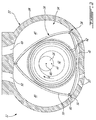
- a Wankel engine Referring to Fig. 2 , an exemplary embodiment of a Wankel engine is shown; it is understood that the configuration of the unit(s) 12 used in the compound cycle engine 10, e.g. placement of ports, number and placement of seals, etc., may vary from that of the embodiment shown; each unit 12 may be defined by a rotary engine other than a Wankel engine.
- each unit 12 comprises a housing 32 defining a rotor cavity with a profile defining two lobes, which is preferably an epitrochoid.
- a rotor 34 is received within the rotor cavity.
- the rotor defines three circumferentially-spaced apex portions 36, and a generally triangular profile with outwardly arched sides.
- the apex portions 36 are in sealing engagement with the inner surface of a peripheral wall 38 of the housing 32 to form three working chambers 40 between the rotor 34 and the housing 32.
- the rotor 34 is engaged to an eccentric portion 42 of the output shaft 16 to perform orbital revolutions within the stator cavity.
- the output shaft 16 performs three rotations for each orbital revolution of the rotor 34.
- the geometrical axis 44 of the rotor 34 is offset from and parallel to the axis 46 of the housing 32.
- each chamber 40 varies in volume and moves around the stator cavity to undergo the four phases of intake, compression, expansion and exhaust.
- An intake port 48 is provided through the peripheral wall 38 for admitting compressed air into one of the working chambers 40.
- An exhaust port 50 is also provided through the peripheral wall 38 for discharge of the exhaust gases from the working chambers 40.
- Passages 52 for a spark plug or other ignition mechanism, as well as for one or more fuel injectors (not shown) are also provided through the peripheral wall 38.
- the intake port 48, the exhaust port 50 and/or the passages 52 may be provided through an end or side wall 54 of the housing.
- the working chambers 40 are sealed, for example by spring-loaded apex seals 56 extending from the rotor 34 to engage the peripheral wall 38, and spring-loaded face or gas seals 58 and end or corner seals 60 extending from the rotor 34 to engage the end walls 54.
- the rotor 34 also includes at least one spring-loaded oil seal ring 62 biased against the end wall 54 around the bearing for the rotor 34 on the shaft eccentric portion 42.
- Each Wankel engine provides an exhaust flow in the form of a relatively long exhaust pulse; for example, in a particular embodiment, each Wankel engine has one explosion per 360° of rotation of the output shaft, with the exhaust port remaining open for about 270° of that rotation, thus providing for a pulse duty cycle of about 75%.
- a piston of a reciprocating 4-stroke piston engine typically has one explosion per 720° of rotation of the output shaft with the exhaust port remaining open for about 180° of that rotation, thus providing a pulse duty cycle of 25%.
- the relatively long exhaust pulse of the Wankel engine may facilitate driving of the first stage turbine 26.
- the inventors have found that in prior art compound engines including one or more rotary engines where the compound turbine is a pressure turbine located downstream of the turbocharger turbine, and where each rotary engine has equal volumetric expansion and compression ratios, the relatively high volumetric compression ratio of the rotary engine(s) typically results in a relatively low possible pressure ratio for the compressor of the turbocharger (P c ), as limited by the peak pressure capability of the rotary engine(s). As such, the pressure ratio across the turbines (P PT P TT ) is limited, which limits the power available for the compound turbine.
- the volumetric compression ratio of each rotary engine is smaller than its expansion ratio.
- the lower volumetric compression ratio typically results in a larger possible pressure ratio for the compressor of the turbocharger (P C ), which in turn increases the pressure ratio across the turbines (P PT P TT ).
- the lower volumetric compression ratio usually leads to an inlet to outlet pressure ratio of the rotary engine(s) which is reduced P R , which may increase back pressure and thermal loads on the rotary engine(s) because of the increased difficulty in purging the exhaust gases.
- P R inlet to outlet pressure ratio of the rotary engine(s)
- Such a configuration also generally provides for a low compression on the rotary engine on start-up before the turbocharger is running, which may limit performances of the compound cycle engine.
- the pressure ratio P PT across the first stage turbine 26 is close to or about 1 since it is a velocity or impulse turbine.
- a same pressure ratio for the compressor P C (to comply with the peak pressure capability) and a same inlet to outlet pressure ratio of the rotary unit(s) P R (to minimize backpressure and thermal loading on each rotary unit) allow for the pressure ratio P TT available for the turbine 22 of the turbocharger 18 to be greater than with a compound cycle engine in which the compound turbine is a pressure turbine, i.e. with a pressure ratio P PT greater than 1 and greater than that of the first stage turbine 26 of the compound cycle engine 10.
- the use of a velocity or impulse turbine as the first stage turbine 26 may allow for an increase of the power available to the turbo compounding.
- the volumetric compression ratio of the rotary unit(s) 12 does not need to be reduced to achieve this increase in power available for the turbine 22 of the turbocharger 18.
- the volumetric efficiency of each rotary unit may be maximized and its thermal loads minimized, and the performances of the compound cycle engine 10 at start-up are not compromised by the increase of available power.
- the use of a velocity or impulse turbine as the first stage turbine 26 eliminates the need for the large volume exhaust collector typically required between the rotary engine(s) and a pressure first stage turbine. This allows for the compound turbine 26 to be located upstream of the turbocharger turbine 22 instead of downstream thereof.
- each rotary unit 12 is a Wankel engine with a volumetric compression ratio of from 6:1 to 8:1.
- the power recovery of the first stage turbine 26 may be maximized by having the exhaust gas temperatures at the material limit, and as such is suitable for such relatively low volumetric compression ratios, which may help increase the power density of the Wankel engine and may also improve combustion at high speed and of heavy fuel.
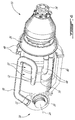
- a compound cycle engine 10 according to a particular embodiment is schematically shown.
- two rotary units 12 in the form of Wankel engines are included, with the two eccentric portions 42 of the output shaft 16 being angularly offset at 180° from one another for balancing of the compound cycle engine 10.
- Fuel injectors 49 ( Fig. 4 ), which may be common rail fuel injectors, communicate with each unit 12. In other embodiments, more or less rotary engines may be provided.
- the rotor blades 64 of the first stage turbine 26 extend across an annular flowpath 66.
- the rotor of the first stage turbine 26 is an axial rotor and the flowpath 66 extends axially.
- a respective exhaust pipe 68 extends from the exhaust port 50 (see also Fig. 2 ) of each unit 12 to a portion of the flowpath 66 located upstream of the rotor blades 64, as shown in Fig. 3 .
- the exhaust pipes 68 extend independently from one another, and their length are minimized to maximize use of the exhaust pulse kinetic energy to drive the first stage turbine 26.
- each exhaust pipe 68 communicates with the flowpath 66 at a different location around the circumference of the first stage turbine 26.
- a pipe 70 extends from an outlet of the compressor 20, and splits into two inlet pipes 72, each connected to the intake port 48 (see also Fig. 2 ) of the respective rotary unit 12.
- the compressor 20 includes a single radial impeller 74.
- the compressor 20 may include one or more rotors, with radial, axial or mixed flow blades.
- the transmission 28 of the first stage turbine 26 includes a sun gear 76 attached on the shaft of the rotor of the first stage turbine 26, and an array of planet gears 78 meshed with the sun gear 76.
- the planet gears 78 are mounted on a rotating carrier which is drivingly engaged to the output shaft 16.
- the planet gears 78 are meshed with a stationary ring gear 79.
- the planet gears 78 are mounted on a stationary carrier, and are meshed with a ring gear drivingly engaged to the output shaft 16.
- the speed reduction ratio of the transmission 28 may be selected to optimize operation of the first stage turbine 26 and of the rotary units 12.
- a turbine pipe 80 extends from a portion of the flowpath 66 downstream of the rotor blades 64 (as shown in Fig. 3 ) to the inlet of the second stage turbine 22 such as to circulate the exhaust flow from the first stage turbine 26 to the second stage turbine 22.
- the second stage turbine 22 includes a single radial impeller 82.
- the second stage turbine 22 may include one or more rotors, with radial, axial or mixed flow blades.
- the turbocharger shaft 24 extends along a different axis than that of the output shaft 16. In the particular embodiment shown in Fig. 4 , the turbocharger shaft 24 extends transverse to the output shaft 16. The turbocharger shaft 24 may additionally be connected to a different load than that of the output shaft 16, through a gearbox if necessary.
- a compound cycle engine 110 according to another embodiment is schematically shown, where elements similar to those of the previously described compound cycle engine 10 are identified by the same reference numerals and will not be further described therein.
- the turbocharger 118 is defined coaxially with the output shaft 16.
- the compressor 120 is connected to the output shaft 16 through an appropriate type of transmission 128, for example a planetary or star gear system.
- the second stage turbine 122 of the turbocharger 118 is connected to the first stage turbine 26 to rotate together therewith, or else connected to the output shaft 16 through an appropriate type of transmission (not shown).
- turbocharger and rotary unit(s) are coaxial, but the output shaft and turbocharger shaft rotate independently from one another, for example with the output shaft being hollow and surrounding the turbocharger shaft which extends therethrough.
- variable geometry elements such as inlet guide vanes, blow-off valves, waste gates, variable turbine nozzles, etc. may be used to obtain desired system operability.
- first stage turbine 26 may be mounted in an offset manner rather than co-axially with the rotary units 12.
- the first stage turbine 26 may be drivingly engaged to the output shaft through an angular, for example perpendicular, transmission system, for example including a gearbox and a tower shaft.
Applications Claiming Priority (1)
| Application Number | Priority Date | Filing Date | Title |
|---|---|---|---|
| US14/740,869 US9926843B2 (en) | 2012-07-20 | 2015-06-16 | Compound cycle engine |
Publications (1)
| Publication Number | Publication Date |
|---|---|
| EP3106643A1 true EP3106643A1 (fr) | 2016-12-21 |
Family
ID=56132850
Family Applications (1)
| Application Number | Title | Priority Date | Filing Date |
|---|---|---|---|
| EP16174757.1A Ceased EP3106643A1 (fr) | 2015-06-16 | 2016-06-16 | Moteur à cycle composé |
Country Status (4)
| Country | Link |
|---|---|
| EP (1) | EP3106643A1 (fr) |
| CN (1) | CN107923310B (fr) |
| CA (1) | CA2933112C (fr) |
| WO (1) | WO2016201567A1 (fr) |
Families Citing this family (4)
| Publication number | Priority date | Publication date | Assignee | Title |
|---|---|---|---|---|
| US20160380776A1 (en) * | 2015-06-29 | 2016-12-29 | Cisco Technology, Inc. | Secured neighbor discovery registration upon device movement |
| CN106895012A (zh) * | 2017-05-05 | 2017-06-27 | 大连依勒斯涡轮增压技术有限公司 | 一种紧凑型两级增压压气机 |
| CN113022863B (zh) * | 2021-04-19 | 2022-07-22 | 中国航发湖南动力机械研究所 | 辅助动力装置及辅助动力装置的排气控制方法 |
| CN113294228B (zh) * | 2021-05-17 | 2022-05-17 | 天津大学 | 一种挥发性有机废气处理系统 |
Citations (6)
| Publication number | Priority date | Publication date | Assignee | Title |
|---|---|---|---|---|
| US4742683A (en) * | 1986-08-18 | 1988-05-10 | Teledyne Industries, Inc. | Turbocompound engine |
| EP2011962A2 (fr) * | 2007-07-02 | 2009-01-07 | United Technologies Corporation | Moteur rotatif à cycle composé |
| US7775044B2 (en) | 2003-02-24 | 2010-08-17 | Pratt & Whitney Canada Corp. | Low volumetric compression ratio integrated turbo-compound rotary engine |
| US20110094221A1 (en) * | 2009-10-23 | 2011-04-28 | Gm Global Technology Operations, Inc. | Turbocharger control systems and methods for improved transient performance |
| EP2687675A2 (fr) * | 2012-07-20 | 2014-01-22 | Pratt & Whitney Canada Corp. | Moteur à cycle composé |
| EP2778342A2 (fr) * | 2013-03-13 | 2014-09-17 | Pratt & Whitney Canada Corp. | Moteur à combustion interne avec communication par port |
Family Cites Families (6)
| Publication number | Priority date | Publication date | Assignee | Title |
|---|---|---|---|---|
| US4815282A (en) * | 1987-02-24 | 1989-03-28 | Teledyne Industries, Inc. | Turbocharged compund cycle ducted fan engine system |
| SU1686202A1 (ru) * | 1989-03-27 | 1991-10-23 | Новосибирский сельскохозяйственный институт | Двигатель внутреннего сгорани |
| CA2516720C (fr) * | 2003-02-24 | 2012-04-24 | Pratt & Whitney Canada Corp. | Moteur rotatif turbo-combine integre a faible taux de compression volumetrique |
| US7438505B2 (en) * | 2004-07-01 | 2008-10-21 | Cudd Pressure Control, Inc. | Heave compensated snubbing system and method |
| US9027345B2 (en) * | 2011-07-28 | 2015-05-12 | Pratt & Whitney Canada Corp. | Compound engine system with rotary engine |
| US9194232B2 (en) * | 2012-07-20 | 2015-11-24 | Pratt & Whitney Canada Corp. | Compound cycle engine |
-
2016
- 2016-06-14 CA CA2933112A patent/CA2933112C/fr active Active
- 2016-06-15 CN CN201680048366.3A patent/CN107923310B/zh active Active
- 2016-06-15 WO PCT/CA2016/050692 patent/WO2016201567A1/fr active Application Filing
- 2016-06-16 EP EP16174757.1A patent/EP3106643A1/fr not_active Ceased
Patent Citations (6)
| Publication number | Priority date | Publication date | Assignee | Title |
|---|---|---|---|---|
| US4742683A (en) * | 1986-08-18 | 1988-05-10 | Teledyne Industries, Inc. | Turbocompound engine |
| US7775044B2 (en) | 2003-02-24 | 2010-08-17 | Pratt & Whitney Canada Corp. | Low volumetric compression ratio integrated turbo-compound rotary engine |
| EP2011962A2 (fr) * | 2007-07-02 | 2009-01-07 | United Technologies Corporation | Moteur rotatif à cycle composé |
| US20110094221A1 (en) * | 2009-10-23 | 2011-04-28 | Gm Global Technology Operations, Inc. | Turbocharger control systems and methods for improved transient performance |
| EP2687675A2 (fr) * | 2012-07-20 | 2014-01-22 | Pratt & Whitney Canada Corp. | Moteur à cycle composé |
| EP2778342A2 (fr) * | 2013-03-13 | 2014-09-17 | Pratt & Whitney Canada Corp. | Moteur à combustion interne avec communication par port |
Also Published As
| Publication number | Publication date |
|---|---|
| CN107923310B (zh) | 2020-03-31 |
| CN107923310A (zh) | 2018-04-17 |
| WO2016201567A1 (fr) | 2016-12-22 |
| CA2933112A1 (fr) | 2016-12-16 |
| CA2933112C (fr) | 2023-09-26 |
Similar Documents
| Publication | Publication Date | Title |
|---|---|---|
| US10968824B2 (en) | Compound cycle engine | |
| US9926843B2 (en) | Compound cycle engine | |
| US10920662B2 (en) | Compound cycle engine | |
| EP2687676B1 (fr) | Moteur à cycle composé | |
| CA2933112C (fr) | Moteur a cycle combine | |
| US10393014B2 (en) | Engine assembly with exhaust pipe nozzle | |
| EP3199754B1 (fr) | Ensemble d'aube directrice d'entrée | |
| EP3106644B1 (fr) | Moteur à cycle composé |
Legal Events
| Date | Code | Title | Description |
|---|---|---|---|
| PUAI | Public reference made under article 153(3) epc to a published international application that has entered the european phase |
Free format text: ORIGINAL CODE: 0009012 |
|
| AK | Designated contracting states |
Kind code of ref document: A1 Designated state(s): AL AT BE BG CH CY CZ DE DK EE ES FI FR GB GR HR HU IE IS IT LI LT LU LV MC MK MT NL NO PL PT RO RS SE SI SK SM TR |
|
| AX | Request for extension of the european patent |
Extension state: BA ME |
|
| 17P | Request for examination filed |
Effective date: 20170620 |
|
| RBV | Designated contracting states (corrected) |
Designated state(s): AL AT BE BG CH CY CZ DE DK EE ES FI FR GB GR HR HU IE IS IT LI LT LU LV MC MK MT NL NO PL PT RO RS SE SI SK SM TR |
|
| 17Q | First examination report despatched |
Effective date: 20170807 |
|
| STAA | Information on the status of an ep patent application or granted ep patent |
Free format text: STATUS: THE APPLICATION HAS BEEN REFUSED |
|
| 18R | Application refused |
Effective date: 20190727 |