EP2687417A1 - Sécurité anti-chocs, en particulier sous forme d'un tampon de crash - Google Patents
Sécurité anti-chocs, en particulier sous forme d'un tampon de crash Download PDFInfo
- Publication number
- EP2687417A1 EP2687417A1 EP13176476.3A EP13176476A EP2687417A1 EP 2687417 A1 EP2687417 A1 EP 2687417A1 EP 13176476 A EP13176476 A EP 13176476A EP 2687417 A1 EP2687417 A1 EP 2687417A1
- Authority
- EP
- European Patent Office
- Prior art keywords
- buffer
- sleeve
- plunger
- end portion
- clamping sleeve
- Prior art date
- Legal status (The legal status is an assumption and is not a legal conclusion. Google has not performed a legal analysis and makes no representation as to the accuracy of the status listed.)
- Granted
Links
- 239000000872 buffer Substances 0.000 title claims abstract description 381
- 230000035939 shock Effects 0.000 claims description 190
- 239000006096 absorbing agent Substances 0.000 claims description 123
- 238000013016 damping Methods 0.000 claims description 47
- 230000021715 photosynthesis, light harvesting Effects 0.000 claims description 29
- 238000006073 displacement reaction Methods 0.000 claims description 22
- 239000000463 material Substances 0.000 claims description 6
- 239000002131 composite material Substances 0.000 claims description 4
- 239000003562 lightweight material Substances 0.000 claims description 4
- 229910052782 aluminium Inorganic materials 0.000 claims description 3
- XAGFODPZIPBFFR-UHFFFAOYSA-N aluminium Chemical compound [Al] XAGFODPZIPBFFR-UHFFFAOYSA-N 0.000 claims description 3
- 239000000835 fiber Substances 0.000 claims description 3
- 230000002093 peripheral effect Effects 0.000 claims 1
- 230000001066 destructive effect Effects 0.000 description 15
- 230000001172 regenerating effect Effects 0.000 description 15
- 238000010276 construction Methods 0.000 description 6
- 230000000694 effects Effects 0.000 description 5
- 238000010521 absorption reaction Methods 0.000 description 4
- 238000005265 energy consumption Methods 0.000 description 4
- 230000005540 biological transmission Effects 0.000 description 3
- 238000005516 engineering process Methods 0.000 description 3
- 230000002427 irreversible effect Effects 0.000 description 3
- 230000000295 complement effect Effects 0.000 description 2
- 230000006835 compression Effects 0.000 description 2
- 238000007906 compression Methods 0.000 description 2
- 238000011161 development Methods 0.000 description 2
- 230000018109 developmental process Effects 0.000 description 2
- 238000010586 diagram Methods 0.000 description 2
- 229910052751 metal Inorganic materials 0.000 description 2
- 239000002184 metal Substances 0.000 description 2
- 238000010008 shearing Methods 0.000 description 2
- 230000007704 transition Effects 0.000 description 2
- 229910000838 Al alloy Inorganic materials 0.000 description 1
- 230000000903 blocking effect Effects 0.000 description 1
- 150000001875 compounds Chemical class 0.000 description 1
- 239000004035 construction material Substances 0.000 description 1
- 230000001419 dependent effect Effects 0.000 description 1
- 229920001971 elastomer Polymers 0.000 description 1
- 239000000806 elastomer Substances 0.000 description 1
- 230000005283 ground state Effects 0.000 description 1
- 238000009434 installation Methods 0.000 description 1
- 230000010354 integration Effects 0.000 description 1
- 238000003032 molecular docking Methods 0.000 description 1
- 238000007639 printing Methods 0.000 description 1
- 230000001681 protective effect Effects 0.000 description 1
- 238000005096 rolling process Methods 0.000 description 1
- 125000006850 spacer group Chemical group 0.000 description 1
- 238000011144 upstream manufacturing Methods 0.000 description 1
Images


Classifications
-
- B—PERFORMING OPERATIONS; TRANSPORTING
- B61—RAILWAYS
- B61G—COUPLINGS; DRAUGHT AND BUFFING APPLIANCES
- B61G11/00—Buffers
- B61G11/02—Buffers with metal springs
- B61G11/04—Buffers with metal springs with helical springs
- B61G11/06—Buffers with metal springs with helical springs arranged to damp each other by mutual friction
-
- B—PERFORMING OPERATIONS; TRANSPORTING
- B61—RAILWAYS
- B61G—COUPLINGS; DRAUGHT AND BUFFING APPLIANCES
- B61G11/00—Buffers
- B61G11/08—Buffers with rubber springs
-
- B—PERFORMING OPERATIONS; TRANSPORTING
- B61—RAILWAYS
- B61G—COUPLINGS; DRAUGHT AND BUFFING APPLIANCES
- B61G11/00—Buffers
- B61G11/16—Buffers absorbing shocks by permanent deformation of buffer element
Definitions
- the present invention relates to a shock absorber, in particular in the form of a crash buffer, wherein the shock absorber comprises a buffer plunger with a plunger sleeve and a buffer arranged at a first end portion of the plunger sleeve and a buffer housing, in which at least one of the first end portion of the plunger sleeve opposite second end portion of the plunger sleeve is recorded telescopically.
- Fender to protect against damage to the outer skin of a ship during port maneuvers and when lying on a quay wall.
- the fender functioning as a protective body is positioned between the ship and the quay wall in such a way that it serves as a shock absorber on the one hand and as a spacer on the other hand so that the hull does not rub.
- fenders are usually used, which are part of a quay.
- Such fenders implemented as part of a quay can be elastic to a certain extent, so that they can, to a certain extent, also participate in the ship movements during docking and in waves.
- the damping of impact forces and the effective distortion of impact energy arising in an impact, especially in a moving object is a problem when due to the mass of the object high movement energies are to be considered, which are to be absorbed after a predictable event in a defined manner.
- bumpers are known from railway technology, which are used to complete a track or stump track of a railway track and to prevent a rail vehicle or a wagon from rolling beyond the end of the rail. Bumpers are usually designed so that as much energy of the moving rail vehicle can be absorbed so that the rail vehicle remains undamaged if possible. Under certain circumstances, the buffer can be deformed or destroyed.
- shock absorbers are also used in the form of bumpers. These are components on vehicles which, in the event of a collision or an impact on a fixed obstacle, absorb energy and thereby prevent damage to the vehicle or the cargo. Bumpers are mainly used on rail vehicles (also referred to as “buffers”, “buffers” or “bumps”), wherein usually one or two attached to the front end construction parts are used, which have the purpose on the rail vehicle in the longitudinal direction of externally acting horizontal compressive forces absorb.
- two types of bumpers can be used in rail vehicles as a shock absorber, namely so-called “buffer” or “central buffer” in which the shock absorber is mounted in the longitudinal axis of the vehicle, so that at each end of the rail vehicle only a buffer in the middle of the head threshold, or so-called “two-buffer” or “side buffer”, in which two buffers are located on the front side of the rail vehicle.
- a telescopic structure which has a buffer housing, a therein at least partially telescopically recorded buffer plunger and a damping element in the form of a spring or an elastomer body.
- the buffer housing serves as a longitudinal guide and for supporting transverse forces, while the damping element accommodated in the buffer housing serves to transmit power in the longitudinal direction.
- the length and the buffer stroke, i. the spring travel of the damping element accommodated in the buffer housing defines the damping property of the side buffer.
- EP 2 036 799 A1 proposed a replaceable energy dissipation unit, which can be connected downstream of a UIC buffer or page buffer as an exchangeable module.
- the energy dissipation unit serves as an additional irreversible shock protection stage, which responds after exhaustion of the energy absorption of integrated in the UIC buffer or side buffer regenerative damping element and by plastic deformation in a destructive manner at least a portion of the initiated in the irreversible shock protection stage impact energy converts into deformation work and heat ,
- a shock absorber with a destructively designed energy absorbing element in the form of a deformation tube known.
- the deformation tube has a section with an expanded cross section and an adjoining section with a not yet expanded cross section, wherein in a crash, a conical ring is pressed into the deformation tube section with the not yet expanded cross section, as a result, a plastic cross-sectional expansion takes place, whereby at least a part the energy generated in a shock transmission is converted into deformation work and heat.
- the known from this prior art shock protection can be provided with a regenerative damping device to dampen the occurring in normal driving tensile / impact forces in a regenerative manner.
- the damping device which is embodied in particular in the form of a spring apparatus, is connected upstream of the deformation pipe section with the not yet expanded cross section in the solution proposed in this prior art.
- the present invention has for its object to provide a shock absorber, which is characterized by a compact design with a high energy consumption, the compact design is also feasible when the shock absorber is used in combination with a regenerative damping device.
- the invention particularly relates to a shock absorber in the form of a crash buffer, wherein the shock absorber has a buffer plunger with a plunger sleeve and a buffer plate arranged on a first end region of the plunger sleeve.
- a buffer housing belongs to the shock absorber in which at least one second end region of the plunger sleeve opposite the first end region of the plunger sleeve is accommodated telescopically.
- the buffer housing has a buffer sleeve with a buffer-plate-side end region and a second end region opposite the buffer-plate-side first end region.
- the buffer sleeve and thus the shock absorber in particular in the form of a crash buffer, can be connected to a support structure to be protected.
- a support structure to be protected This may be, for example, the front side of a car body, a subframe of a car body, a stationary buffer block or, for example, a quay or part of a quay wall.
- the buffer housing further has a clamping sleeve with a buffer end side first end region and a second end region opposite the buffer end side first end region.
- the clamping sleeve is connected to the first end portion of the buffer sleeve of the buffer housing.
- the buffer housing further has a destructive energy dissipation element, which is designed in particular in the form of a deformation tube.
- the energy dissipation element is clamped between the first end region of the clamping sleeve and the first end region of the buffer sleeve.
- the plunger sleeve is formed as a circular cylindrical body, namely deart that the plunger sleeve has a substantially constant outer diameter from its first end portion to its opposite second end portion.
- the shock absorber according to the invention is characterized in particular by the unique and above-described construction of the buffer housing, which also ensures a compact construction of the shock protection, if in addition to the destructive energy dissipation element a regenerative damping device is used, with which before the plastic deformation of the destructive energy dissipation element regenerative tensile / impact forces are damped.
- a conical-ring-shaped region is provided at the first end region of the buffer sleeve, against which a region of the buffer sleeve facing the energy dissipation element, preferably designed as a deformation tube, abuts.
- the conical-ring-shaped region is preferably designed such that, when a critical impact force introduced via the buffer plate into the shock protection is exceeded, the energy dissipation element, which is preferably designed as a deformation tube, is pushed over the buffer sleeve under plastic cross-sectional widening.
- the conical-ring-shaped region preferably has a conically tapered lateral surface in the direction of the energy dissipation element designed as a deformation tube.
- the buffer sleeve of the buffer housing has a cylindrical outer circumferential surface, so that in this way a guide is provided to guide the plastically expanded portion of the energy absorbing element in a longitudinal displacement of this relative to the buffer sleeve in response of the energy dissipation element preferably designed as a deformation tube.
- the shock absorber can not only reduce the impact energy generated in a crash case, at least partially by plastic deformation of the destructively designed energy dissipation element, but also in the normal Driving operation occurring shocks or tensile forces can dampen, is provided in a preferred realization of the solution according to the invention that at least before exceeding a introduced via the buffer plate of the shock absorber in the shock protection pre-definable critical impact force of the buffer ram relative to the buffer housing in the direction of the buffer sleeve is displaceable ,
- a Leksverschiebungsweg by which the buffer plunger is displaceable relative to the buffer housing in the direction of the buffer sleeve can be defined or limited according to an aspect of the present invention by a stop, in particular an annular circumferential stop, with a bufferteller characteren at the first end portion of the clamping sleeve Stop surface is provided, said bufferteller side stop surface of the clamping sleeve limits the longitudinal displacement travel of the buffer plunger relative to the buffer housing.
- a regenerative damping device is provided in order to be able to dampen the tensile and impact forces occurring in normal driving operation in a regenerative manner.
- the damping device formed for example in the form of a spring apparatus is at least partially accommodated in the plunger sleeve and arranged between a first pressure plate connected to the plunger sleeve and a second pressure plate connected to the buffer housing.
- the shock absorber is provided with a regenerative damping device
- the first pressure plate is preferably formed by the buffer plate and abuts the damping device to a pointing in the direction of the buffer housing surface of the buffer plate, said the second pressure plate is connected to the second end region of the clamping sleeve.
- the present invention is characterized not only by a compact design of the shock absorber, but also by the fact that a longitudinal displacement of the buffer plunger takes place relative to the buffer housing after a predetermined defined event sequence.
- a guide is provided to guide the longitudinal displacement of the buffer plunger relative to the buffer housing.
- the leadership Has at least one extending in the longitudinal direction of the plunger sleeve and in the longitudinal direction of the buffer housing guide groove and engaging in the at least one guide pin. It should be noted that in the shock absorber according to the invention, the plunger sleeve and the buffer housing are arranged coaxially and concentrically, so that the longitudinal direction of the plunger sleeve coincides with the longitudinal direction of the buffer housing.
- a particularly compact design of the shock absorber can be realized if the at least one guide groove is formed in the buffer sleeve, wherein the engaging in the at least one guide pin is connected to the clamping sleeve of the buffer housing.
- the engaging in the at least one guide pin extends in the longitudinal direction of the plunger sleeve or in the longitudinal direction of the buffer housing and is preferably connected to the second end portion of the clamping sleeve with the clamping sleeve.
- This embodiment allows a variable stroke of the buffer ram while blocking the rotational degree of freedom.
- the pin which runs laterally in the at least one guide groove produces virtually no notch effects on the components involved. This makes it possible to use smaller material cross-sections and thus to reduce given sizes with simultaneous load or higher load with the same size.
- a stop in particular an annular circumferential stop, provided with a buffer sleeve side stop surface, which preferably designed as a deformation tube destructive Energy absorbing element between the buffer sleeve side abutment surface of the clamping sleeve and the first end portion of the buffer sleeve is clamped.
- This construction makes it possible to use a deformation tube for the destructively designed energy dissipation element, wherein the deformation tube is a rotating part which is provided without a widening, as is otherwise customary in deformation tubes. This allows installation of the destructive energy dissipation element in the shock protection in a small space and beyond a cost-effective design.
- the second end portion of the clamping sleeve is at least partially telescopically received in the first end portion of the buffer sleeve and abuts against a bufferteller workede stop surface of a first provided inside the first end portion of the buffer sleeve, preferably annular abutment of the buffer sleeve.
- a arranged in the interior of the buffer sleeve counter element is provided, which abuts on the one hand against one of the buffer plate side abutment surfaces opposite stop surface of the first stop, and which on the other hand against a stop surface of a second inside the first end of the Buffer sleeve provided preferably annular abutment of the buffer sleeve abuts, wherein the counter element is preferably connected by means of screws with the second end portion of the clamping sleeve such that the first stop of the buffer sleeve is received between the clamping sleeve and the counter element.
- the connection between the second end of the clamping sleeve and the first end of the buffer sleeve can be solved and the clamping sleeve together with the deformation tube with simultaneous plastic deformation of the deformation deformation can be moved towards the buffer sleeve in the direction of the buffer sleeve is provided in a preferred embodiment of the last-mentioned embodiment that the first stop is designed such that it shears when exceeding the pre-definable critical impact force, so that the clamping sleeve relative to the buffer sleeve in the direction the buffer sleeve is displaceable.
- the end face of the first end region of the plunger sleeve is wedge-shaped. This wedge-shaped end face of the plunger sleeve can then engage in a correspondingly complementary groove formed in the buffer plate, so that the assembly of the shock protection is simplified.
- the buffer sleeve, the Verformunsrohr, the clamping sleeve and the plunger sleeve are formed of different materials.
- suitable materials for the aforementioned components with regard to the required stiffness or strength and in terms of their weight are selected.
- shock absorber according to the invention will be described with reference to the accompanying drawings.
- the embodiments shown in the drawings are suitable, for example, as shock protection in track-guided vehicles, in particular rail vehicles, or as shock absorbers in maritime applications, for example as an integral part of a quay.
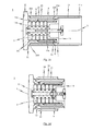
- Fig. 1 is an exemplary embodiment of a shock absorber 1 is shown in a perspective view.
- the exemplary embodiment is a crash buffer, which can be mounted, for example, on the front of a car body or on a stationary buffer bracket.
- the shock absorber 1 has a buffer ram 10 and a buffer housing 20.
- the buffer housing 20 facing the end portion of the buffer plunger 10 is received in the buffer housing 20 telescopically.
- Fig. 2a which shows the exemplary embodiment of the shock absorber 1 in a side view.
- the shock absorber is 1 in Fig. 2a shown in an unloaded state, ie in a state in which no pressure forces act on the buffer plunger 10.
- the buffer plunger 10 used in the exemplary embodiment of the shock absorber 1 consists in detail of a plunger sleeve 11, as shown in a perspective view in FIG Fig. 9 respectively. Fig. 10 is shown.
- the plunger sleeve 11 has a first end region 11a, on which a buffer plate 12 is attached, in particular welded.
- a first end region 11a of the plunger sleeve 11 opposite second end portion 11b of the plunger sleeve 11 is telescopically received in the assembled state of the shock absorber 1 in the buffer housing 20 of the shock absorber 1.
- the plunger sleeve 11 and the buffer housing 20 are arranged coaxially and concentrically with one another (cf. Fig. 2a ).
- the buffer case 20 is basically constituted by a buffer sleeve 21, a collet 22, and a deformation tube 23.
- the buffer sleeve 21 has a buffer end side first end portion 21a and a second end portion 21b opposite to the first end portion 21a.
- the buffer sleeve 21 is connected to a support structure, in particular with the front side of a car body, with the undercarriage of a car body or with a stationary buffer bracket.
- a flange arrangement 2 is provided on the second end region 21b of the buffer sleeve 21.
- the clamping sleeve 22 belonging to the buffer housing 20 has a buffer end side first end region 22a and a second end region 22b opposite the first end region 22a. Via the second end region 22b, the clamping sleeve 22 is connected to the first end region 21a of the buffer sleeve 21, as described below with regard to the first exemplary embodiment of the shock absorber 1 with reference to the illustrations in FIGS FIGS. 3a to 3d will be described in more detail.
- the exemplary embodiments of the shock absorber 1 have as a destructive energy dissipation element in each case a deformation tube 23 which - as in particular the exploded view according to Fig. 4 or the exploded view according to Fig. 6a can be removed - is designed as a cylindrical rotary member without any widening etc.
- the deformation tube 23 used as a destructive energy dissipation element is located between the first end region 22a of the clamping sleeve 22 and the clamped first end portion 21a of the buffer sleeve 21, as in particular the side sectional view according to Fig. 3a can be removed.
- Fig. 3a the exemplary embodiment of the shock absorber 1 shown in a side sectional view, wherein 10 no pressure forces are introduced into the buffer plate 12 of the buffer ram.
- the first exemplary embodiment of designed in the form of a crash buffer shock absorber 1 is designed to at least in a crash, ie when exceeding a introduced via the buffer plate 12 in the shock protection 1 pre-definable critical impact force, under plastic cross-sectional deformation of the deformation tube 23 to reduce part of the initiated impact energy and thus to consume.
- shock absorber 1 is designed to dampen tensile and impact forces before exceeding a initiated in the shock protection 1 critical impact force.
- the shock absorber 1 a regenerative damping device 3, which - as in the FIGS. 3a to 3d shown - can be designed as a spring pack.
- the damping device 3 is at least partially received in the plunger sleeve 11 and disposed between a connected to the plunger sleeve 11 first pressure plate 13a and connected to the buffer housing 20 second pressure plate 13b.
- the first pressure plate 13a is formed by the buffer plate 12, wherein the damping device 3 abuts a pointing in the direction of the buffer housing 20 surface of the buffer plate 12.
- the second pressure plate 13b is connected in the exemplary embodiment of the shock absorber 1 with the second end portion 22b of the clamping sleeve 22.
- a stop 25 connected to the clamping sleeve 22.
- This stop 25 has a pointing in the direction of the buffer plate 12 first stop surface 25a, which ultimately limits the longitudinal displacement of the buffer plunger 10 relative to the buffer housing 20 in the direction of the buffer sleeve 21.
- the clamping sleeve 22 associated stop 25 is preferably an annular circumferential stop.
- the exemplary embodiment of the shock protection 1 shown in the drawings with a special guide for guiding the longitudinal displacement of the buffer ram 10 is relative provided to the buffer housing 20.
- the guide for guiding the longitudinal displacement of the buffer plunger 10 relative to the buffer housing 20 at least one in the longitudinal direction L of the plunger sleeve 11 (or in the longitudinal direction L of the buffer housing 20) extending guide groove 4. In this at least one guide groove 4 engages a corresponding pin or guide pin 5 a.
- the guide pin 5 used for guiding the longitudinal displacement of the buffer plunger 10 relative to the buffer housing 20 in the exemplary embodiment of the shock absorber 1 is shown in a perspective view in FIG Fig. 13 shown.
- Fig. 11 shows a perspective view of the clamping sleeve 22 of the buffer housing 20 of the exemplary embodiment of the shock absorber 1
- Fig. 12 a side sectional view of the clamping sleeve 22 shows.
- Guide pin 5 are held in elongated receptacles 26 which are formed in the inner circumferential surface of the clamping sleeve 22 (see. Fig. 12 ).
- the pins / guide pins 5 are inserted through corresponding pin openings 5 'at the second end portion 22b of the clamping sleeve 22.
- the engaging in the corresponding guide groove 4 of the plunger sleeve 11 pin / guide pin 5 is connected to the second end portion 22b of the clamping sleeve 22 with the clamping sleeve 22.
- the pin / guide pin 5 is held partially in the assembled state of the shock absorber 1 in a corresponding in the clamping sleeve 22, and in detail provided in the inner circumferential surface of the clamping sleeve 22 elongated receptacle 26.
- the second end portion 22b of the clamping sleeve 22, with which the respective pins / guide pins 5 are connected, is at least partially telescopically received in the first end portion 21a of the buffer sleeve 21 and abuts in the direction of the buffer sleeve 21 against a bufferteller workede stop surface 6a of a first inside the first end portion 21a of the buffer sleeve 21 provided stop 6 of the buffer sleeve 21.
- This connected to the buffer sleeve 21 first stop 6 is preferably annular.
- a counter element 14 is also provided in the exemplary embodiment of the shock absorber 1.
- the counter element 14 is shown in the illustrations in the FIGS. 3a to 3d with the second pressure plate 13b, against which the recorded in the shock absorber 1 damping device 3 abuts connected.
- the counter element 14 accommodated in the interior of the buffer sleeve 21 abuts against a stop surface 6b of the first stop 6 facing the buffer plate side abutment 6.
- the counter element 14 abuts against a stop surface 7a of a second inside the first end region 21a and the buffer sleeve 21 Stop 7 of the buffer sleeve 21.
- first stop 6 of the second sleeve 7 connected to the buffer sleeve 21 is preferably annular.
- the counter element 14 is connected by means of screws 8 with the second end portion 22b of the clamping sleeve 22, in such a way that the first stop 6 of the buffer sleeve 21 is received between the clamping sleeve 22 and the counter element 14.
- a single common Stop to use as in the second exemplary embodiment of the solution according to the invention as shown in the FIGS. 5a to 5d the case is.
- the first stopper 6 connected to the buffer sleeve 21 is formed in the exemplary embodiment of the shock absorber 1 such that it shears off at a predetermined above the buffer plate 12 introduced into the shock protection 1 pre-definable critical impact force and thus its connection with the buffer sleeve 21 loses.
- the clamping sleeve 22 is then displaceable relative to the buffer sleeve 21 in the direction of the buffer sleeve 21.
- FIG. 3a in a side sectional view formed in the form of a crash buffer shock protection 1 in the unloaded state, ie in a state in which no pressure forces on the buffer plate 12 are introduced into the shock absorber 1.
- the buffer plunger 10 In this unloaded state, the buffer plunger 10 is in its maximum extended state, ie in a state in which the buffer plate 12 is farthest from the buffer housing 10.
- This in Fig. 3a shown state is the ground state of the shock absorber 1, which is taken independently of the shock absorber 1 when no pressure forces are introduced into the buffer plate 12.
- This basic state is predetermined by the damping device 3 provided in the interior of the shock absorber 1 and biased between the first pressure plate 13a (here buffer plate 12) and the second pressure plate 13b.
- Fig. 3b is a side view of the exemplary embodiment of the shock absorber 1 after exhaustion of the damping behavior of the shock absorber 1 integrated damping device 3 is shown.
- the shock absorber 1 can absorb or reduce any further impact forces in a regenerative manner.
- the destructively designed energy dissipation element responds to the shock absorber 1.
- a preferably cylindrically symmetric deformation tube 23 is used, which can be designed in particular as a rotating part without necessary expansions.
- the deformation tube 23 is arranged, in particular clamped, between the first end region 22a of the clamping sleeve 22 and the first end region 21a of the buffer sleeve 21 of the buffer housing 20.
- the stopper 25 formed on the first end portion 22a of the collet 22 is used, which has an opposed, i.e., in opposition to, the first abutment surface 25a for limiting the longitudinal displacement travel of the buffer plunger 10 relative to the buffer housing 20. in the direction of buffer sleeve 21 facing, second stop surface 25b. Against this second abutment surface 25 b abuts the bufferteller workede end portion of the clamped between the clamping sleeve 22 and the buffer sleeve 21 deformation tube 23rd
- the first stop 6 is in the exemplary embodiment of the shock absorber according to the invention designed as shearing element, which shears when exceeding a pre-definable critical impact force and solves the connection of the clamping sleeve 22 to the buffer sleeve 21. This condition is in Fig. 3c shown.
- the direct power transmission is interrupted by the clamping sleeve 22 to the buffer sleeve 21 via the first stop 6, the resulting impact energy over the stop 25 of the clamping sleeve 22 in the deformation tube 23 and from there into the first end portion 21a of the buffer sleeve 21 initiated.
- the deformation tube is plastically deformed, in particular when the buffer ram 10 is displaced with the clamping sleeve 22 in the direction of the buffer sleeve 21.
- a conical-ring-shaped region 24 is provided at the first end region of the buffer sleeve 21 in order to support the plastic cross-sectional widening of the deformation tube 23, and in particular to prevent tilting of components when the shock absorber 1 responds.
- the buffer sleeve 21 has a cylindrical outer circumferential surface 28, which is designed to guide a plastically expanded region of the deformation tube 23 with a longitudinal displacement of the deformation tube 23 relative to the buffer sleeve 21 after exceeding the pre-definable critical impact force.
- FIGS. 5a to 5d Side sectional views of a second exemplary embodiment of the shock absorber 1 are shown in different states of shock protection.
- Fig. 5a the second embodiment of the shock absorber 1 according to the invention shown in a side sectional view, wherein 10 no pressure forces are introduced into the buffer plate 12 of the buffer plunger.
- the buffer plunger 10 In this unloaded state, the buffer plunger 10 is in its maximum extended state, ie in a state in which the buffer plate 12 is farthest from the buffer housing 10.
- This in Fig. 5a shown state is the Basic state of the shock absorber 1, which is taken independently of the shock protection 1 when no pressure forces are introduced into the buffer plate 12.
- This basic state is predetermined by the damping device 3 provided in the interior of the shock absorber 1 and biased between the first pressure plate 13a (here buffer plate 12) and the second pressure plate 13b.
- Fig. 5b is a side view of the second embodiment of the shock absorber 1 according to the invention after exhaustion of the damping behavior of the shock absorber 1 integrated damping device 3 is shown.
- the shock absorber 1 can absorb or reduce any further impact forces in a regenerative manner.
- the destructively designed energy dissipation element responds to the shock absorber 1.
- a preferably cylindrically symmetric deformation tube 23 is used, which can be designed in particular as a rotating part without necessary expansions.
- the deformation tube 23 is arranged, in particular clamped, between the first end region 22a of the clamping sleeve 22 and the first end region 21a of the buffer sleeve 21 of the buffer housing 20.
- first end portion 22a of the clamping sleeve 22nd trained stop 25 is used, in addition to the first stop surface 25a, which serves to limit the L Lucassverschiebungsweges the buffer plunger 10 relative to the buffer housing 20, an opposite, ie in the direction of the buffer sleeve 21 facing, second stop surface 25b.
- second abutment surface 25 b abuts the bufferteller workede end portion of the clamped between the clamping sleeve 22 and the buffer sleeve 21 deformation tube 23rd
- the first stop 6 is designed as a shearing element, which shears off when a critical impact force that can be predetermined is exceeded and releases the connection of the clamping sleeve 22 to the buffer sleeve 21. This condition is in Fig. 5c shown.
- the direct power transmission is interrupted by the clamping sleeve 22 to the buffer sleeve 21 via the first stop 6, the resulting impact energy over the stop 25 of the clamping sleeve 22 in the deformation tube 23 and from there into the first end portion 21a of the buffer sleeve 21 initiated.
- the deformation tube is plastically deformed, in particular when the buffer ram 10 is displaced with the clamping sleeve 22 in the direction of the buffer sleeve 21.
- a conical-ring-shaped region 24 is provided at the first end region of the buffer sleeve 21 in order to support the plastic cross-sectional widening of the deformation tube 23, and in particular to prevent tilting of components when the shock absorber 1 responds.
- the buffer sleeve 21 has a cylindrical outer circumferential surface 28, which is designed to guide a plastically expanded region of the deformation tube 23 with a longitudinal displacement of the deformation tube 23 relative to the buffer sleeve 21 after exceeding the pre-definable critical impact force.
- FIG. 2 The structure and functioning of the in the FIGS. 5a to 5d
- the second exemplary embodiment shown in FIG. 2 essentially corresponds to the construction and the mode of operation of the previously described with reference to the illustrations in FIGS FIGS. 3a to 3d described first exemplary embodiment. In order to avoid repetition, only the differences between the two embodiments will be discussed briefly below:
- FIGS. 5a to 5d illustrated second exemplary embodiment of the shock absorber 1 according to the invention of the first embodiment according to the FIGS. 3a to 3d in that now only a single annular stop 6 is used, instead of two separate stops 6, 7 as in the first embodiment.
- the counter element 14 has a slightly modified configuration, which will be described below with reference to the illustrations in FIGS. 6a, 6b . 7a, 7b and 8a, 8b will be described in more detail.
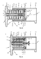
- Fig. 6a in a perspective view, a first assembly step
- Fig. 6b in a side sectional view illustrating the shock absorber 1 after performing the first assembly step.
- the plunger sleeve 11 is first provided with the buffer plate 12 connected to the first end region 11a.
- the representation in Fig. 6a It can also be seen that in the outer circumferential surface of the plunger sleeve 11 already in the longitudinal direction L of the shock protection 1 extending guide grooves 4 are introduced.
- the damping device 3 which is formed in the exemplary embodiment as a spring assembly consisting of a plurality of coaxially and concentrically aligned spring plates, received in the interior of the plunger sleeve 11.
- a guide rod 30 is used, which is inserted into the plunger sleeve 11 and locked there accordingly.
- a securing piece 31 is to be introduced via the guide rod 30 into the plunger sleeve 11.
- the securing piece 31 is used for fixing the guide rod 30 in the interior of the plunger sleeve 11 such that the guide rod 30 is located on the longitudinal axis L of the shock absorber 1.
- a clamping sleeve 32 is attached to the exposed end portion of the guide rod 30 to the damping device 3 against the first pressure plate 13 a (the inside Side wall of the buffer plate 12).
- This condition is in Fig. 6b shown in a side sectional view of the shock protection 1.
- the protruding from the second end portion 11b of the plunger sleeve 11 part of the damping device 3 and attached to the guide rod 30 clamping sleeve 32 is - as soon as the second End portion 11b of the plunger sleeve 11 is telescopically received by the clamping sleeve 22 together with the inside of the plunger sleeve 11 at least partially absorbed damping device 3 - fixed by means of screws 33 to a second end portion 22b of the clamping sleeve 22 flange plate 34.
- the buffer sleeve 21 is then mounted together with the destructive energy dissipation element (deformation tube 23).
- the guide pin 5 are first introduced in the third assembly step from behind through the flange plate 34 in the elongated receptacles 26 which are formed in the clamping sleeve 22.
- corresponding pin openings 5 ' are formed in the flange plate 34.
- the guide pin 5 partially in the elongated receptacles 26, while a part of the guide pin 5 engages in the guide groove 4 of the plunger sleeve 11 like a rail.
- the destructive energy dissipation element formed in particular in the form of a deformation tube 23 from the rear, i. Slid over the second end portion 22b of the clamping sleeve 22 on the clamping sleeve 22 until the deformation tube 23 abuts the second stop surface 25b of the first end portion 22a of the clamping sleeve 22 provided stop 25.
- the composite is connected to the first end portion 21 a of the buffer sleeve 21.
- a plate-shaped counter element 14 is used, which is inserted from behind into the buffer sleeve 21, until it abuts against the second provided in the interior of the first end portion 21a of the buffer sleeve 21 annular stop 7 of the buffer sleeve 21.
- the counter element 14 is connected by means of screws 8 with the second end portion 22b of the clamping sleeve 22 such that the first stop 6 of the buffer sleeve 21 is received between the clamping sleeve 22 and the counter element 14.
- FIGS. 15 to 27 the structure and operation of an exemplary embodiment of the shock absorber 1 according to the invention described.
- FIG. 15 in a perspective view of the exemplary embodiment of the shock absorber 1 according to the invention.
- a side view of the exemplary embodiment is shown in FIG Fig. 16a shown, in an unloaded state of the shock absorber 1, ie in a state in which no pressure forces acting on the buffer plunger 10 of the shock absorber 1.
- the exemplary embodiment of the shock absorber 1 also has a buffer ram 10 and a buffer housing 20.
- the buffer housing 20 facing the end portion of the buffer plunger 10 is received in the buffer housing 20 telescopically.
- the buffer plunger 10 consists essentially of a plunger sleeve 11, as in a perspective view in Fig. 23 is shown.
- the ram sleeve 11 used in the exemplary embodiment of the shock absorber 1 is designed as a circular-cylindrical body, which has a substantial outer diameter from the first end portion 11a of the ram sleeve 11 to the opposite second end portion 11b of the ram sleeve 11.
- the plunger sleeve 11 In contrast to the plunger sleeve, which is used in the first and second exemplary embodiment of the shock absorber 1, in the plunger sleeve 11 according to the exemplary embodiment of the inventive solution, in particular the first end portion 11a of the plunger sleeve 11 is not expanded. In this way, when a critical impact force is introduced into the buffer tappet 10, an (unwanted) deformation of the tappet sleeve 11 can be effectively prevented.
- the end face of the first end portion 11a of the plunger sleeve 11 is wedge-shaped.
- the buffer plate 12 is provided a complementary to the wedge-shaped end face formed groove to receive the first end portion 11 a of the plunger sleeve 11.
- the structure of the shock absorber 1 according to the exemplary embodiment of the shock absorber 1 according to the invention substantially corresponds to the structure of the first and second exemplary embodiments described above. To avoid repetition, reference is therefore made to the previous statements.
- a further (fourth) assembly step in the Figs. 21a and 21b is shown.
- a response indicator 35 is attached to the already mounted shock absorber 1, which is designed to indicate whether the deformation tube 23 integrated in the shock absorber 1 has possibly already been mentioned.
- the response indicator 35 is formed as a sheet-metal strip at the transition point between the deformation tube 23 and the buffer sleeve 21. As soon as the deformation tube 23 has also pushed on the buffer sleeve 21 only slightly, this is indicated on the basis of the response indicator 35, since it deforms or flakes off accordingly.
- a difference is to be seen in the fact that in Fig. 24 illustrated clamping sleeve 22, which is used in the exemplary embodiment of the shock absorber 1 according to the invention, the pin openings 5 'in comparison to the illustration in Fig. 11 are arranged rotated.
- the invention is not limited to the exemplified embodiment of the crash buffer designed as crash buffer, but results from a synopsis of all features disclosed herein.
- the shock absorber 1 according to the invention is provided with a response indicator 35 to indicate whether the integrated in the shock absorber 1 deformation tube 23 has possibly already addressed.
- the response indicator 35 is formed as a sheet-metal strip at the transition point between the deformation tube 23 and the buffer sleeve 21. As soon as the deformation tube 23 only partially on the buffer sleeve 21 has pushed, this is indicated by the response indicator 35, since this deforms accordingly or flakes off.
- the individual components of the shock absorber 1 are formed from materials which are optimized in terms of weight.
- the buffer sleeve 21, the deformation tube 23, the clamping sleeve 22 and / or the plunger sleeve 11 are formed from a lightweight material / is.
- a lightweight material is in particular aluminum, an aluminum alloy or a fiber composite material in question. It is of course conceivable that the aforementioned components of the shock absorber 1 from different materials (in particular lightweight materials) are formed.
Landscapes
- Engineering & Computer Science (AREA)
- Mechanical Engineering (AREA)
- Vibration Dampers (AREA)
Priority Applications (2)
| Application Number | Priority Date | Filing Date | Title |
|---|---|---|---|
| EP13176476.3A EP2687417B1 (fr) | 2012-07-16 | 2013-07-15 | Sécurité anti-chocs, en particulier sous forme d'un tampon de crash |
| PL13176476T PL2687417T3 (pl) | 2012-07-16 | 2013-07-15 | Zabezpieczenie przed uderzeniem, zwłaszcza w postaci zderzaka kolizyjnego |
Applications Claiming Priority (2)
| Application Number | Priority Date | Filing Date | Title |
|---|---|---|---|
| EP12176549.9A EP2687416B1 (fr) | 2012-07-16 | 2012-07-16 | Sécurité anti-chocs, en particulier sous forme d'un tampon de crash |
| EP13176476.3A EP2687417B1 (fr) | 2012-07-16 | 2013-07-15 | Sécurité anti-chocs, en particulier sous forme d'un tampon de crash |
Publications (2)
| Publication Number | Publication Date |
|---|---|
| EP2687417A1 true EP2687417A1 (fr) | 2014-01-22 |
| EP2687417B1 EP2687417B1 (fr) | 2015-03-04 |
Family
ID=48748092
Family Applications (2)
| Application Number | Title | Priority Date | Filing Date |
|---|---|---|---|
| EP12176549.9A Active EP2687416B1 (fr) | 2012-07-16 | 2012-07-16 | Sécurité anti-chocs, en particulier sous forme d'un tampon de crash |
| EP13176476.3A Active EP2687417B1 (fr) | 2012-07-16 | 2013-07-15 | Sécurité anti-chocs, en particulier sous forme d'un tampon de crash |
Family Applications Before (1)
| Application Number | Title | Priority Date | Filing Date |
|---|---|---|---|
| EP12176549.9A Active EP2687416B1 (fr) | 2012-07-16 | 2012-07-16 | Sécurité anti-chocs, en particulier sous forme d'un tampon de crash |
Country Status (3)
| Country | Link |
|---|---|
| EP (2) | EP2687416B1 (fr) |
| CN (1) | CN203727625U (fr) |
| PL (2) | PL2687416T3 (fr) |
Cited By (6)
| Publication number | Priority date | Publication date | Assignee | Title |
|---|---|---|---|---|
| CN109974527A (zh) * | 2019-04-28 | 2019-07-05 | 吉林大学 | 防爆吸能装置 |
| CN112148156A (zh) * | 2020-09-17 | 2020-12-29 | 深圳市嘉中电子有限公司 | 一种厚度薄的触摸屏 |
| EP3771610A1 (fr) * | 2019-07-29 | 2021-02-03 | Falk Schneider | Tampon plongeur à résistance mécanique lors du mouvement télescopique |
| CN113445452A (zh) * | 2021-07-12 | 2021-09-28 | 长沙理工大学 | 一种新型剪切挤胀吸能的可导向防撞垫 |
| CN114775514A (zh) * | 2022-04-13 | 2022-07-22 | 中交第四航务工程勘察设计院有限公司 | 积木式重力方块码头 |
| US20220242463A1 (en) * | 2021-01-29 | 2022-08-04 | Amsted Rail Company, Inc. | Modular crash energy management systems for car coupling systems of rail cars |
Families Citing this family (7)
| Publication number | Priority date | Publication date | Assignee | Title |
|---|---|---|---|---|
| DE102014216061A1 (de) | 2014-08-13 | 2016-02-18 | Siemens Aktiengesellschaft | Schienenfahrzeug mit im Bereich seiner Front angeordneter Kupplung |
| DE102016203921A1 (de) | 2016-03-10 | 2017-09-14 | Voith Patent Gmbh | Auslöseüberwachungseinrichtung für ein Verformungsrohr in einer Kupplung; Verformungsrohr für eine Kupplung und Zugkupplung |
| US10669016B2 (en) * | 2017-04-21 | 2020-06-02 | The Boeing Company | Tail skid shock absorber and indicator |
| PL233589B1 (pl) * | 2017-08-29 | 2019-11-29 | Axtone Spolka Akcyjna | Aparat pochlaniajacy |
| CN109653131B (zh) * | 2018-12-26 | 2023-06-27 | 长安大学 | 一种消能护栏装置 |
| CN112208937B (zh) * | 2020-09-29 | 2022-04-15 | 常州宏业包装材料有限公司 | 一种不易变形的纸箱 |
| CN116398567B (zh) * | 2023-03-27 | 2023-09-22 | 江苏科技大学 | 波纹型薄壁三层缓冲吸能结构及其制作方法 |
Citations (9)
| Publication number | Priority date | Publication date | Assignee | Title |
|---|---|---|---|---|
| DE457171C (de) * | 1927-01-27 | 1928-03-09 | Wilhelm Wurl | Elsenbahnhuelsenpuffer |
| GB882724A (en) * | 1957-09-07 | 1961-11-15 | Garringtons Ltd | Improvements relating to railway buffers |
| DE3610567A1 (de) * | 1986-03-27 | 1987-10-01 | Ringfeder Gmbh | Huelsenpuffer zur federnden aufnahme von stosskraeften, insbesondere fuer schienenfahrzeuge |
| EP1247716A1 (fr) * | 2001-04-04 | 2002-10-09 | Oleo International Limited | Tampon à deux phases |
| WO2005115818A1 (fr) * | 2004-04-27 | 2005-12-08 | Sieghard Schneider | Tampon a boisseau |
| US20090065462A1 (en) * | 2007-09-11 | 2009-03-12 | Voith Patent Gmbh | Shock absorber |
| EP2036799A1 (fr) | 2007-09-11 | 2009-03-18 | Voith Patent GmbH | Unité d'absorption d'énergie échangeable, en particulier pour l'utilisation en association avec un tampon |
| WO2010071468A2 (fr) * | 2008-09-22 | 2010-06-24 | S.C., Innova Sisteme Si Tehnologii S.R.L. | Butoir d'écrasement pour véhicules de chemin de fer |
| WO2012016723A1 (fr) | 2010-08-06 | 2012-02-09 | Voith Patent Gmbh | Dispositif d'absorption d'énergie, en particulier pour un dispositif d'absorption des chocs d'un véhicule guidé |
-
2012
- 2012-07-16 PL PL12176549T patent/PL2687416T3/pl unknown
- 2012-07-16 EP EP12176549.9A patent/EP2687416B1/fr active Active
-
2013
- 2013-07-15 EP EP13176476.3A patent/EP2687417B1/fr active Active
- 2013-07-15 PL PL13176476T patent/PL2687417T3/pl unknown
- 2013-07-16 CN CN201320420379.2U patent/CN203727625U/zh not_active Expired - Fee Related
Patent Citations (9)
| Publication number | Priority date | Publication date | Assignee | Title |
|---|---|---|---|---|
| DE457171C (de) * | 1927-01-27 | 1928-03-09 | Wilhelm Wurl | Elsenbahnhuelsenpuffer |
| GB882724A (en) * | 1957-09-07 | 1961-11-15 | Garringtons Ltd | Improvements relating to railway buffers |
| DE3610567A1 (de) * | 1986-03-27 | 1987-10-01 | Ringfeder Gmbh | Huelsenpuffer zur federnden aufnahme von stosskraeften, insbesondere fuer schienenfahrzeuge |
| EP1247716A1 (fr) * | 2001-04-04 | 2002-10-09 | Oleo International Limited | Tampon à deux phases |
| WO2005115818A1 (fr) * | 2004-04-27 | 2005-12-08 | Sieghard Schneider | Tampon a boisseau |
| US20090065462A1 (en) * | 2007-09-11 | 2009-03-12 | Voith Patent Gmbh | Shock absorber |
| EP2036799A1 (fr) | 2007-09-11 | 2009-03-18 | Voith Patent GmbH | Unité d'absorption d'énergie échangeable, en particulier pour l'utilisation en association avec un tampon |
| WO2010071468A2 (fr) * | 2008-09-22 | 2010-06-24 | S.C., Innova Sisteme Si Tehnologii S.R.L. | Butoir d'écrasement pour véhicules de chemin de fer |
| WO2012016723A1 (fr) | 2010-08-06 | 2012-02-09 | Voith Patent Gmbh | Dispositif d'absorption d'énergie, en particulier pour un dispositif d'absorption des chocs d'un véhicule guidé |
Cited By (7)
| Publication number | Priority date | Publication date | Assignee | Title |
|---|---|---|---|---|
| CN109974527A (zh) * | 2019-04-28 | 2019-07-05 | 吉林大学 | 防爆吸能装置 |
| EP3771610A1 (fr) * | 2019-07-29 | 2021-02-03 | Falk Schneider | Tampon plongeur à résistance mécanique lors du mouvement télescopique |
| CN112148156A (zh) * | 2020-09-17 | 2020-12-29 | 深圳市嘉中电子有限公司 | 一种厚度薄的触摸屏 |
| CN112148156B (zh) * | 2020-09-17 | 2023-02-10 | 深圳市嘉中电子有限公司 | 一种触摸屏 |
| US20220242463A1 (en) * | 2021-01-29 | 2022-08-04 | Amsted Rail Company, Inc. | Modular crash energy management systems for car coupling systems of rail cars |
| CN113445452A (zh) * | 2021-07-12 | 2021-09-28 | 长沙理工大学 | 一种新型剪切挤胀吸能的可导向防撞垫 |
| CN114775514A (zh) * | 2022-04-13 | 2022-07-22 | 中交第四航务工程勘察设计院有限公司 | 积木式重力方块码头 |
Also Published As
| Publication number | Publication date |
|---|---|
| PL2687416T3 (pl) | 2015-02-27 |
| CN203727625U (zh) | 2014-07-23 |
| EP2687416B1 (fr) | 2014-09-03 |
| EP2687417B1 (fr) | 2015-03-04 |
| EP2687416A1 (fr) | 2014-01-22 |
| PL2687417T3 (pl) | 2015-08-31 |
Similar Documents
| Publication | Publication Date | Title |
|---|---|---|
| EP2687417B1 (fr) | Sécurité anti-chocs, en particulier sous forme d'un tampon de crash | |
| EP2188165B1 (fr) | Amortisseur | |
| EP2036799B1 (fr) | Unité d'absorption d'énergie échangeable, en particulier pour l'utilisation en association avec un tampon | |
| EP1719684B1 (fr) | Attelage central pour véhicules ferroviaires | |
| EP2601088B1 (fr) | Dispositif d'absorption d'énergie, en particulier pour un dispositif d'absorption des chocs d'un véhicule guidé | |
| EP2072370B1 (fr) | Dispositif d'absorption d'énergie pour une caisse d'un véhicule composé de plusieurs unités | |
| EP1990251B1 (fr) | Dispositif d'absorption d'énergie pour véhicules à éléments multiples | |
| EP2594452B1 (fr) | Dispositif d'embrayage pour la zone frontale d'un véhicule guidé sur rails | |
| DE3833048A1 (de) | Stossfaenger fuer kraftfahrzeuge, insbesondere personenkraftwagen | |
| EP3442847B1 (fr) | Dispositif de traction et de poussée | |
| AT510958B1 (de) | Anordnung zur umlenkung einer durch das versagen einer überlastsicherung im zuge eines zusammenstosses abgetrennten mittelpufferkupplung eines schienenfahrzeugs | |
| EP2925588B1 (fr) | Dispositif d'amortissement de forces de compression | |
| EP2230147B1 (fr) | Elément de consommation d'énergie et sécurité contre les chocs dotée d'un élément de consommation d'énergie | |
| EP2694348B1 (fr) | Véhicule ferroviaire à zone de déformation | |
| EP3530544B1 (fr) | Dispositif de déformation pourvu de protection anti-chevauchement pour véhicules ferroviaires | |
| EP3205551B1 (fr) | Dispositif d'attelage pour un vehicule sur rails | |
| DE102014108979A1 (de) | Vorrichtung zur Absorption von Energie bei einem Fahrzeugaufprall | |
| DE102008027811B4 (de) | Stoßfängeranordnung | |
| EP3670286B1 (fr) | Véhicule remorqué à voyageurs et véhicule ferroviaire | |
| EP3560787B1 (fr) | Véhicule sur rail | |
| DE102012014375B4 (de) | Strukturbauteil mit Energieabbaufunktion und Kraftfahrzeug mit einem solchen Strukturbauteil | |
| EP3594082B1 (fr) | Tampon anti-crash à barre de guidage, structure portante et véhicule ferroviaire | |
| EP3810482B1 (fr) | Dispositif de raccordement comprenant un absorbeur d'énergie et caisson de wagon | |
| DE102018130253A1 (de) | Crashpuffer mit führungsstange, tragstruktur und schienenfahrzeug | |
| WO2013167534A1 (fr) | Véhicule ferroviaire à sécurité accrue contre le déraillement |
Legal Events
| Date | Code | Title | Description |
|---|---|---|---|
| PUAI | Public reference made under article 153(3) epc to a published international application that has entered the european phase |
Free format text: ORIGINAL CODE: 0009012 |
|
| AK | Designated contracting states |
Kind code of ref document: A1 Designated state(s): AL AT BE BG CH CY CZ DE DK EE ES FI FR GB GR HR HU IE IS IT LI LT LU LV MC MK MT NL NO PL PT RO RS SE SI SK SM TR |
|
| AX | Request for extension of the european patent |
Extension state: BA ME |
|
| 17P | Request for examination filed |
Effective date: 20140428 |
|
| RBV | Designated contracting states (corrected) |
Designated state(s): AL AT BE BG CH CY CZ DE DK EE ES FI FR GB GR HR HU IE IS IT LI LT LU LV MC MK MT NL NO PL PT RO RS SE SI SK SM TR |
|
| GRAP | Despatch of communication of intention to grant a patent |
Free format text: ORIGINAL CODE: EPIDOSNIGR1 |
|
| INTG | Intention to grant announced |
Effective date: 20141021 |
|
| GRAS | Grant fee paid |
Free format text: ORIGINAL CODE: EPIDOSNIGR3 |
|
| GRAA | (expected) grant |
Free format text: ORIGINAL CODE: 0009210 |
|
| AK | Designated contracting states |
Kind code of ref document: B1 Designated state(s): AL AT BE BG CH CY CZ DE DK EE ES FI FR GB GR HR HU IE IS IT LI LT LU LV MC MK MT NL NO PL PT RO RS SE SI SK SM TR |
|
| REG | Reference to a national code |
Ref country code: GB Ref legal event code: FG4D Free format text: NOT ENGLISH |
|
| REG | Reference to a national code |
Ref country code: CH Ref legal event code: EP |
|
| REG | Reference to a national code |
Ref country code: IE Ref legal event code: FG4D Free format text: LANGUAGE OF EP DOCUMENT: GERMAN |
|
| REG | Reference to a national code |
Ref country code: AT Ref legal event code: REF Ref document number: 713577 Country of ref document: AT Kind code of ref document: T Effective date: 20150415 |
|
| REG | Reference to a national code |
Ref country code: DE Ref legal event code: R096 Ref document number: 502013000408 Country of ref document: DE Effective date: 20150416 |
|
| REG | Reference to a national code |
Ref country code: SE Ref legal event code: TRGR |
|
| REG | Reference to a national code |
Ref country code: FR Ref legal event code: PLFP Year of fee payment: 3 |
|
| REG | Reference to a national code |
Ref country code: NL Ref legal event code: VDEP Effective date: 20150304 |
|
| PG25 | Lapsed in a contracting state [announced via postgrant information from national office to epo] |
Ref country code: FI Free format text: LAPSE BECAUSE OF FAILURE TO SUBMIT A TRANSLATION OF THE DESCRIPTION OR TO PAY THE FEE WITHIN THE PRESCRIBED TIME-LIMIT Effective date: 20150304 Ref country code: HR Free format text: LAPSE BECAUSE OF FAILURE TO SUBMIT A TRANSLATION OF THE DESCRIPTION OR TO PAY THE FEE WITHIN THE PRESCRIBED TIME-LIMIT Effective date: 20150304 Ref country code: NO Free format text: LAPSE BECAUSE OF FAILURE TO SUBMIT A TRANSLATION OF THE DESCRIPTION OR TO PAY THE FEE WITHIN THE PRESCRIBED TIME-LIMIT Effective date: 20150604 Ref country code: LT Free format text: LAPSE BECAUSE OF FAILURE TO SUBMIT A TRANSLATION OF THE DESCRIPTION OR TO PAY THE FEE WITHIN THE PRESCRIBED TIME-LIMIT Effective date: 20150304 Ref country code: ES Free format text: LAPSE BECAUSE OF FAILURE TO SUBMIT A TRANSLATION OF THE DESCRIPTION OR TO PAY THE FEE WITHIN THE PRESCRIBED TIME-LIMIT Effective date: 20150304 |
|
| REG | Reference to a national code |
Ref country code: LT Ref legal event code: MG4D |
|
| PG25 | Lapsed in a contracting state [announced via postgrant information from national office to epo] |
Ref country code: RS Free format text: LAPSE BECAUSE OF FAILURE TO SUBMIT A TRANSLATION OF THE DESCRIPTION OR TO PAY THE FEE WITHIN THE PRESCRIBED TIME-LIMIT Effective date: 20150304 Ref country code: LV Free format text: LAPSE BECAUSE OF FAILURE TO SUBMIT A TRANSLATION OF THE DESCRIPTION OR TO PAY THE FEE WITHIN THE PRESCRIBED TIME-LIMIT Effective date: 20150304 Ref country code: GR Free format text: LAPSE BECAUSE OF FAILURE TO SUBMIT A TRANSLATION OF THE DESCRIPTION OR TO PAY THE FEE WITHIN THE PRESCRIBED TIME-LIMIT Effective date: 20150605 |
|
| REG | Reference to a national code |
Ref country code: PL Ref legal event code: T3 |
|
| PG25 | Lapsed in a contracting state [announced via postgrant information from national office to epo] |
Ref country code: NL Free format text: LAPSE BECAUSE OF FAILURE TO SUBMIT A TRANSLATION OF THE DESCRIPTION OR TO PAY THE FEE WITHIN THE PRESCRIBED TIME-LIMIT Effective date: 20150304 |
|
| PG25 | Lapsed in a contracting state [announced via postgrant information from national office to epo] |
Ref country code: EE Free format text: LAPSE BECAUSE OF FAILURE TO SUBMIT A TRANSLATION OF THE DESCRIPTION OR TO PAY THE FEE WITHIN THE PRESCRIBED TIME-LIMIT Effective date: 20150304 Ref country code: CZ Free format text: LAPSE BECAUSE OF FAILURE TO SUBMIT A TRANSLATION OF THE DESCRIPTION OR TO PAY THE FEE WITHIN THE PRESCRIBED TIME-LIMIT Effective date: 20150304 Ref country code: PT Free format text: LAPSE BECAUSE OF FAILURE TO SUBMIT A TRANSLATION OF THE DESCRIPTION OR TO PAY THE FEE WITHIN THE PRESCRIBED TIME-LIMIT Effective date: 20150706 Ref country code: RO Free format text: LAPSE BECAUSE OF FAILURE TO SUBMIT A TRANSLATION OF THE DESCRIPTION OR TO PAY THE FEE WITHIN THE PRESCRIBED TIME-LIMIT Effective date: 20150304 Ref country code: SK Free format text: LAPSE BECAUSE OF FAILURE TO SUBMIT A TRANSLATION OF THE DESCRIPTION OR TO PAY THE FEE WITHIN THE PRESCRIBED TIME-LIMIT Effective date: 20150304 |
|
| PG25 | Lapsed in a contracting state [announced via postgrant information from national office to epo] |
Ref country code: IS Free format text: LAPSE BECAUSE OF FAILURE TO SUBMIT A TRANSLATION OF THE DESCRIPTION OR TO PAY THE FEE WITHIN THE PRESCRIBED TIME-LIMIT Effective date: 20150704 |
|
| REG | Reference to a national code |
Ref country code: DE Ref legal event code: R097 Ref document number: 502013000408 Country of ref document: DE |
|
| PG25 | Lapsed in a contracting state [announced via postgrant information from national office to epo] |
Ref country code: IT Free format text: LAPSE BECAUSE OF FAILURE TO SUBMIT A TRANSLATION OF THE DESCRIPTION OR TO PAY THE FEE WITHIN THE PRESCRIBED TIME-LIMIT Effective date: 20150304 |
|
| PLBE | No opposition filed within time limit |
Free format text: ORIGINAL CODE: 0009261 |
|
| STAA | Information on the status of an ep patent application or granted ep patent |
Free format text: STATUS: NO OPPOSITION FILED WITHIN TIME LIMIT |
|
| PG25 | Lapsed in a contracting state [announced via postgrant information from national office to epo] |
Ref country code: DK Free format text: LAPSE BECAUSE OF FAILURE TO SUBMIT A TRANSLATION OF THE DESCRIPTION OR TO PAY THE FEE WITHIN THE PRESCRIBED TIME-LIMIT Effective date: 20150304 |
|
| 26N | No opposition filed |
Effective date: 20151207 |
|
| PG25 | Lapsed in a contracting state [announced via postgrant information from national office to epo] |
Ref country code: SI Free format text: LAPSE BECAUSE OF FAILURE TO SUBMIT A TRANSLATION OF THE DESCRIPTION OR TO PAY THE FEE WITHIN THE PRESCRIBED TIME-LIMIT Effective date: 20150304 Ref country code: MC Free format text: LAPSE BECAUSE OF FAILURE TO SUBMIT A TRANSLATION OF THE DESCRIPTION OR TO PAY THE FEE WITHIN THE PRESCRIBED TIME-LIMIT Effective date: 20150304 |
|
| PG25 | Lapsed in a contracting state [announced via postgrant information from national office to epo] |
Ref country code: LU Free format text: LAPSE BECAUSE OF FAILURE TO SUBMIT A TRANSLATION OF THE DESCRIPTION OR TO PAY THE FEE WITHIN THE PRESCRIBED TIME-LIMIT Effective date: 20150715 |
|
| REG | Reference to a national code |
Ref country code: IE Ref legal event code: MM4A |
|
| REG | Reference to a national code |
Ref country code: FR Ref legal event code: PLFP Year of fee payment: 4 |
|
| PG25 | Lapsed in a contracting state [announced via postgrant information from national office to epo] |
Ref country code: IE Free format text: LAPSE BECAUSE OF NON-PAYMENT OF DUE FEES Effective date: 20150715 |
|
| PG25 | Lapsed in a contracting state [announced via postgrant information from national office to epo] |
Ref country code: MT Free format text: LAPSE BECAUSE OF FAILURE TO SUBMIT A TRANSLATION OF THE DESCRIPTION OR TO PAY THE FEE WITHIN THE PRESCRIBED TIME-LIMIT Effective date: 20150304 |
|
| PG25 | Lapsed in a contracting state [announced via postgrant information from national office to epo] |
Ref country code: HU Free format text: LAPSE BECAUSE OF FAILURE TO SUBMIT A TRANSLATION OF THE DESCRIPTION OR TO PAY THE FEE WITHIN THE PRESCRIBED TIME-LIMIT; INVALID AB INITIO Effective date: 20130715 Ref country code: BG Free format text: LAPSE BECAUSE OF FAILURE TO SUBMIT A TRANSLATION OF THE DESCRIPTION OR TO PAY THE FEE WITHIN THE PRESCRIBED TIME-LIMIT Effective date: 20150304 |
|
| PG25 | Lapsed in a contracting state [announced via postgrant information from national office to epo] |
Ref country code: CY Free format text: LAPSE BECAUSE OF FAILURE TO SUBMIT A TRANSLATION OF THE DESCRIPTION OR TO PAY THE FEE WITHIN THE PRESCRIBED TIME-LIMIT Effective date: 20150304 |
|
| REG | Reference to a national code |
Ref country code: FR Ref legal event code: PLFP Year of fee payment: 5 |
|
| PG25 | Lapsed in a contracting state [announced via postgrant information from national office to epo] |
Ref country code: BE Free format text: LAPSE BECAUSE OF NON-PAYMENT OF DUE FEES Effective date: 20150731 |
|
| GBPC | Gb: european patent ceased through non-payment of renewal fee |
Effective date: 20170715 |
|
| PG25 | Lapsed in a contracting state [announced via postgrant information from national office to epo] |
Ref country code: GB Free format text: LAPSE BECAUSE OF NON-PAYMENT OF DUE FEES Effective date: 20170715 |
|
| PG25 | Lapsed in a contracting state [announced via postgrant information from national office to epo] |
Ref country code: SM Free format text: LAPSE BECAUSE OF FAILURE TO SUBMIT A TRANSLATION OF THE DESCRIPTION OR TO PAY THE FEE WITHIN THE PRESCRIBED TIME-LIMIT Effective date: 20150304 |
|
| PG25 | Lapsed in a contracting state [announced via postgrant information from national office to epo] |
Ref country code: TR Free format text: LAPSE BECAUSE OF FAILURE TO SUBMIT A TRANSLATION OF THE DESCRIPTION OR TO PAY THE FEE WITHIN THE PRESCRIBED TIME-LIMIT Effective date: 20150304 Ref country code: MK Free format text: LAPSE BECAUSE OF FAILURE TO SUBMIT A TRANSLATION OF THE DESCRIPTION OR TO PAY THE FEE WITHIN THE PRESCRIBED TIME-LIMIT Effective date: 20150304 |
|
| REG | Reference to a national code |
Ref country code: FR Ref legal event code: PLFP Year of fee payment: 6 |
|
| PG25 | Lapsed in a contracting state [announced via postgrant information from national office to epo] |
Ref country code: AL Free format text: LAPSE BECAUSE OF FAILURE TO SUBMIT A TRANSLATION OF THE DESCRIPTION OR TO PAY THE FEE WITHIN THE PRESCRIBED TIME-LIMIT Effective date: 20150304 |
|
| PGFP | Annual fee paid to national office [announced via postgrant information from national office to epo] |
Ref country code: PL Payment date: 20190627 Year of fee payment: 7 |
|
| PGFP | Annual fee paid to national office [announced via postgrant information from national office to epo] |
Ref country code: FR Payment date: 20190719 Year of fee payment: 7 Ref country code: SE Payment date: 20190719 Year of fee payment: 7 |
|
| PGFP | Annual fee paid to national office [announced via postgrant information from national office to epo] |
Ref country code: AT Payment date: 20190722 Year of fee payment: 7 |
|
| PGFP | Annual fee paid to national office [announced via postgrant information from national office to epo] |
Ref country code: CH Payment date: 20190719 Year of fee payment: 7 |
|
| REG | Reference to a national code |
Ref country code: CH Ref legal event code: PL |
|
| REG | Reference to a national code |
Ref country code: SE Ref legal event code: EUG |
|
| REG | Reference to a national code |
Ref country code: AT Ref legal event code: MM01 Ref document number: 713577 Country of ref document: AT Kind code of ref document: T Effective date: 20200715 |
|
| PG25 | Lapsed in a contracting state [announced via postgrant information from national office to epo] |
Ref country code: FR Free format text: LAPSE BECAUSE OF NON-PAYMENT OF DUE FEES Effective date: 20200731 Ref country code: CH Free format text: LAPSE BECAUSE OF NON-PAYMENT OF DUE FEES Effective date: 20200731 Ref country code: LI Free format text: LAPSE BECAUSE OF NON-PAYMENT OF DUE FEES Effective date: 20200731 |
|
| PG25 | Lapsed in a contracting state [announced via postgrant information from national office to epo] |
Ref country code: AT Free format text: LAPSE BECAUSE OF NON-PAYMENT OF DUE FEES Effective date: 20200715 Ref country code: SE Free format text: LAPSE BECAUSE OF NON-PAYMENT OF DUE FEES Effective date: 20200716 |
|
| PG25 | Lapsed in a contracting state [announced via postgrant information from national office to epo] |
Ref country code: PL Free format text: LAPSE BECAUSE OF NON-PAYMENT OF DUE FEES Effective date: 20200715 |
|
| PGFP | Annual fee paid to national office [announced via postgrant information from national office to epo] |
Ref country code: DE Payment date: 20230719 Year of fee payment: 11 |