EP2687417A1 - Impact protection, in particular in the form of a crash buffer - Google Patents
Impact protection, in particular in the form of a crash buffer Download PDFInfo
- Publication number
- EP2687417A1 EP2687417A1 EP13176476.3A EP13176476A EP2687417A1 EP 2687417 A1 EP2687417 A1 EP 2687417A1 EP 13176476 A EP13176476 A EP 13176476A EP 2687417 A1 EP2687417 A1 EP 2687417A1
- Authority
- EP
- European Patent Office
- Prior art keywords
- buffer
- sleeve
- plunger
- end portion
- clamping sleeve
- Prior art date
- Legal status (The legal status is an assumption and is not a legal conclusion. Google has not performed a legal analysis and makes no representation as to the accuracy of the status listed.)
- Granted
Links
- 239000000872 buffer Substances 0.000 title claims abstract description 381
- 230000035939 shock Effects 0.000 claims description 190
- 239000006096 absorbing agent Substances 0.000 claims description 123
- 238000013016 damping Methods 0.000 claims description 47
- 230000021715 photosynthesis, light harvesting Effects 0.000 claims description 29
- 238000006073 displacement reaction Methods 0.000 claims description 22
- 239000000463 material Substances 0.000 claims description 6
- 239000002131 composite material Substances 0.000 claims description 4
- 239000003562 lightweight material Substances 0.000 claims description 4
- 229910052782 aluminium Inorganic materials 0.000 claims description 3
- XAGFODPZIPBFFR-UHFFFAOYSA-N aluminium Chemical compound [Al] XAGFODPZIPBFFR-UHFFFAOYSA-N 0.000 claims description 3
- 239000000835 fiber Substances 0.000 claims description 3
- 230000002093 peripheral effect Effects 0.000 claims 1
- 230000001066 destructive effect Effects 0.000 description 15
- 230000001172 regenerating effect Effects 0.000 description 15
- 238000010276 construction Methods 0.000 description 6
- 230000000694 effects Effects 0.000 description 5
- 238000010521 absorption reaction Methods 0.000 description 4
- 238000005265 energy consumption Methods 0.000 description 4
- 230000005540 biological transmission Effects 0.000 description 3
- 238000005516 engineering process Methods 0.000 description 3
- 230000002427 irreversible effect Effects 0.000 description 3
- 230000000295 complement effect Effects 0.000 description 2
- 230000006835 compression Effects 0.000 description 2
- 238000007906 compression Methods 0.000 description 2
- 238000011161 development Methods 0.000 description 2
- 230000018109 developmental process Effects 0.000 description 2
- 238000010586 diagram Methods 0.000 description 2
- 229910052751 metal Inorganic materials 0.000 description 2
- 239000002184 metal Substances 0.000 description 2
- 238000010008 shearing Methods 0.000 description 2
- 230000007704 transition Effects 0.000 description 2
- 229910000838 Al alloy Inorganic materials 0.000 description 1
- 230000000903 blocking effect Effects 0.000 description 1
- 150000001875 compounds Chemical class 0.000 description 1
- 239000004035 construction material Substances 0.000 description 1
- 230000001419 dependent effect Effects 0.000 description 1
- 229920001971 elastomer Polymers 0.000 description 1
- 239000000806 elastomer Substances 0.000 description 1
- 230000005283 ground state Effects 0.000 description 1
- 238000009434 installation Methods 0.000 description 1
- 230000010354 integration Effects 0.000 description 1
- 238000003032 molecular docking Methods 0.000 description 1
- 238000007639 printing Methods 0.000 description 1
- 230000001681 protective effect Effects 0.000 description 1
- 238000005096 rolling process Methods 0.000 description 1
- 125000006850 spacer group Chemical group 0.000 description 1
- 238000011144 upstream manufacturing Methods 0.000 description 1
Images


Classifications
-
- B—PERFORMING OPERATIONS; TRANSPORTING
- B61—RAILWAYS
- B61G—COUPLINGS; DRAUGHT AND BUFFING APPLIANCES
- B61G11/00—Buffers
- B61G11/02—Buffers with metal springs
- B61G11/04—Buffers with metal springs with helical springs
- B61G11/06—Buffers with metal springs with helical springs arranged to damp each other by mutual friction
-
- B—PERFORMING OPERATIONS; TRANSPORTING
- B61—RAILWAYS
- B61G—COUPLINGS; DRAUGHT AND BUFFING APPLIANCES
- B61G11/00—Buffers
- B61G11/08—Buffers with rubber springs
-
- B—PERFORMING OPERATIONS; TRANSPORTING
- B61—RAILWAYS
- B61G—COUPLINGS; DRAUGHT AND BUFFING APPLIANCES
- B61G11/00—Buffers
- B61G11/16—Buffers absorbing shocks by permanent deformation of buffer element
Definitions
- the present invention relates to a shock absorber, in particular in the form of a crash buffer, wherein the shock absorber comprises a buffer plunger with a plunger sleeve and a buffer arranged at a first end portion of the plunger sleeve and a buffer housing, in which at least one of the first end portion of the plunger sleeve opposite second end portion of the plunger sleeve is recorded telescopically.
- Fender to protect against damage to the outer skin of a ship during port maneuvers and when lying on a quay wall.
- the fender functioning as a protective body is positioned between the ship and the quay wall in such a way that it serves as a shock absorber on the one hand and as a spacer on the other hand so that the hull does not rub.
- fenders are usually used, which are part of a quay.
- Such fenders implemented as part of a quay can be elastic to a certain extent, so that they can, to a certain extent, also participate in the ship movements during docking and in waves.
- the damping of impact forces and the effective distortion of impact energy arising in an impact, especially in a moving object is a problem when due to the mass of the object high movement energies are to be considered, which are to be absorbed after a predictable event in a defined manner.
- bumpers are known from railway technology, which are used to complete a track or stump track of a railway track and to prevent a rail vehicle or a wagon from rolling beyond the end of the rail. Bumpers are usually designed so that as much energy of the moving rail vehicle can be absorbed so that the rail vehicle remains undamaged if possible. Under certain circumstances, the buffer can be deformed or destroyed.
- shock absorbers are also used in the form of bumpers. These are components on vehicles which, in the event of a collision or an impact on a fixed obstacle, absorb energy and thereby prevent damage to the vehicle or the cargo. Bumpers are mainly used on rail vehicles (also referred to as “buffers”, “buffers” or “bumps”), wherein usually one or two attached to the front end construction parts are used, which have the purpose on the rail vehicle in the longitudinal direction of externally acting horizontal compressive forces absorb.
- two types of bumpers can be used in rail vehicles as a shock absorber, namely so-called “buffer” or “central buffer” in which the shock absorber is mounted in the longitudinal axis of the vehicle, so that at each end of the rail vehicle only a buffer in the middle of the head threshold, or so-called “two-buffer” or “side buffer”, in which two buffers are located on the front side of the rail vehicle.
- a telescopic structure which has a buffer housing, a therein at least partially telescopically recorded buffer plunger and a damping element in the form of a spring or an elastomer body.
- the buffer housing serves as a longitudinal guide and for supporting transverse forces, while the damping element accommodated in the buffer housing serves to transmit power in the longitudinal direction.
- the length and the buffer stroke, i. the spring travel of the damping element accommodated in the buffer housing defines the damping property of the side buffer.
- EP 2 036 799 A1 proposed a replaceable energy dissipation unit, which can be connected downstream of a UIC buffer or page buffer as an exchangeable module.
- the energy dissipation unit serves as an additional irreversible shock protection stage, which responds after exhaustion of the energy absorption of integrated in the UIC buffer or side buffer regenerative damping element and by plastic deformation in a destructive manner at least a portion of the initiated in the irreversible shock protection stage impact energy converts into deformation work and heat ,
- a shock absorber with a destructively designed energy absorbing element in the form of a deformation tube known.
- the deformation tube has a section with an expanded cross section and an adjoining section with a not yet expanded cross section, wherein in a crash, a conical ring is pressed into the deformation tube section with the not yet expanded cross section, as a result, a plastic cross-sectional expansion takes place, whereby at least a part the energy generated in a shock transmission is converted into deformation work and heat.
- the known from this prior art shock protection can be provided with a regenerative damping device to dampen the occurring in normal driving tensile / impact forces in a regenerative manner.
- the damping device which is embodied in particular in the form of a spring apparatus, is connected upstream of the deformation pipe section with the not yet expanded cross section in the solution proposed in this prior art.
- the present invention has for its object to provide a shock absorber, which is characterized by a compact design with a high energy consumption, the compact design is also feasible when the shock absorber is used in combination with a regenerative damping device.
- the invention particularly relates to a shock absorber in the form of a crash buffer, wherein the shock absorber has a buffer plunger with a plunger sleeve and a buffer plate arranged on a first end region of the plunger sleeve.
- a buffer housing belongs to the shock absorber in which at least one second end region of the plunger sleeve opposite the first end region of the plunger sleeve is accommodated telescopically.
- the buffer housing has a buffer sleeve with a buffer-plate-side end region and a second end region opposite the buffer-plate-side first end region.
- the buffer sleeve and thus the shock absorber in particular in the form of a crash buffer, can be connected to a support structure to be protected.
- a support structure to be protected This may be, for example, the front side of a car body, a subframe of a car body, a stationary buffer block or, for example, a quay or part of a quay wall.
- the buffer housing further has a clamping sleeve with a buffer end side first end region and a second end region opposite the buffer end side first end region.
- the clamping sleeve is connected to the first end portion of the buffer sleeve of the buffer housing.
- the buffer housing further has a destructive energy dissipation element, which is designed in particular in the form of a deformation tube.
- the energy dissipation element is clamped between the first end region of the clamping sleeve and the first end region of the buffer sleeve.
- the plunger sleeve is formed as a circular cylindrical body, namely deart that the plunger sleeve has a substantially constant outer diameter from its first end portion to its opposite second end portion.
- the shock absorber according to the invention is characterized in particular by the unique and above-described construction of the buffer housing, which also ensures a compact construction of the shock protection, if in addition to the destructive energy dissipation element a regenerative damping device is used, with which before the plastic deformation of the destructive energy dissipation element regenerative tensile / impact forces are damped.
- a conical-ring-shaped region is provided at the first end region of the buffer sleeve, against which a region of the buffer sleeve facing the energy dissipation element, preferably designed as a deformation tube, abuts.
- the conical-ring-shaped region is preferably designed such that, when a critical impact force introduced via the buffer plate into the shock protection is exceeded, the energy dissipation element, which is preferably designed as a deformation tube, is pushed over the buffer sleeve under plastic cross-sectional widening.
- the conical-ring-shaped region preferably has a conically tapered lateral surface in the direction of the energy dissipation element designed as a deformation tube.
- the buffer sleeve of the buffer housing has a cylindrical outer circumferential surface, so that in this way a guide is provided to guide the plastically expanded portion of the energy absorbing element in a longitudinal displacement of this relative to the buffer sleeve in response of the energy dissipation element preferably designed as a deformation tube.
- the shock absorber can not only reduce the impact energy generated in a crash case, at least partially by plastic deformation of the destructively designed energy dissipation element, but also in the normal Driving operation occurring shocks or tensile forces can dampen, is provided in a preferred realization of the solution according to the invention that at least before exceeding a introduced via the buffer plate of the shock absorber in the shock protection pre-definable critical impact force of the buffer ram relative to the buffer housing in the direction of the buffer sleeve is displaceable ,
- a Leksverschiebungsweg by which the buffer plunger is displaceable relative to the buffer housing in the direction of the buffer sleeve can be defined or limited according to an aspect of the present invention by a stop, in particular an annular circumferential stop, with a bufferteller characteren at the first end portion of the clamping sleeve Stop surface is provided, said bufferteller side stop surface of the clamping sleeve limits the longitudinal displacement travel of the buffer plunger relative to the buffer housing.
- a regenerative damping device is provided in order to be able to dampen the tensile and impact forces occurring in normal driving operation in a regenerative manner.
- the damping device formed for example in the form of a spring apparatus is at least partially accommodated in the plunger sleeve and arranged between a first pressure plate connected to the plunger sleeve and a second pressure plate connected to the buffer housing.
- the shock absorber is provided with a regenerative damping device
- the first pressure plate is preferably formed by the buffer plate and abuts the damping device to a pointing in the direction of the buffer housing surface of the buffer plate, said the second pressure plate is connected to the second end region of the clamping sleeve.
- the present invention is characterized not only by a compact design of the shock absorber, but also by the fact that a longitudinal displacement of the buffer plunger takes place relative to the buffer housing after a predetermined defined event sequence.
- a guide is provided to guide the longitudinal displacement of the buffer plunger relative to the buffer housing.
- the leadership Has at least one extending in the longitudinal direction of the plunger sleeve and in the longitudinal direction of the buffer housing guide groove and engaging in the at least one guide pin. It should be noted that in the shock absorber according to the invention, the plunger sleeve and the buffer housing are arranged coaxially and concentrically, so that the longitudinal direction of the plunger sleeve coincides with the longitudinal direction of the buffer housing.
- a particularly compact design of the shock absorber can be realized if the at least one guide groove is formed in the buffer sleeve, wherein the engaging in the at least one guide pin is connected to the clamping sleeve of the buffer housing.
- the engaging in the at least one guide pin extends in the longitudinal direction of the plunger sleeve or in the longitudinal direction of the buffer housing and is preferably connected to the second end portion of the clamping sleeve with the clamping sleeve.
- This embodiment allows a variable stroke of the buffer ram while blocking the rotational degree of freedom.
- the pin which runs laterally in the at least one guide groove produces virtually no notch effects on the components involved. This makes it possible to use smaller material cross-sections and thus to reduce given sizes with simultaneous load or higher load with the same size.
- a stop in particular an annular circumferential stop, provided with a buffer sleeve side stop surface, which preferably designed as a deformation tube destructive Energy absorbing element between the buffer sleeve side abutment surface of the clamping sleeve and the first end portion of the buffer sleeve is clamped.
- This construction makes it possible to use a deformation tube for the destructively designed energy dissipation element, wherein the deformation tube is a rotating part which is provided without a widening, as is otherwise customary in deformation tubes. This allows installation of the destructive energy dissipation element in the shock protection in a small space and beyond a cost-effective design.
- the second end portion of the clamping sleeve is at least partially telescopically received in the first end portion of the buffer sleeve and abuts against a bufferteller workede stop surface of a first provided inside the first end portion of the buffer sleeve, preferably annular abutment of the buffer sleeve.
- a arranged in the interior of the buffer sleeve counter element is provided, which abuts on the one hand against one of the buffer plate side abutment surfaces opposite stop surface of the first stop, and which on the other hand against a stop surface of a second inside the first end of the Buffer sleeve provided preferably annular abutment of the buffer sleeve abuts, wherein the counter element is preferably connected by means of screws with the second end portion of the clamping sleeve such that the first stop of the buffer sleeve is received between the clamping sleeve and the counter element.
- the connection between the second end of the clamping sleeve and the first end of the buffer sleeve can be solved and the clamping sleeve together with the deformation tube with simultaneous plastic deformation of the deformation deformation can be moved towards the buffer sleeve in the direction of the buffer sleeve is provided in a preferred embodiment of the last-mentioned embodiment that the first stop is designed such that it shears when exceeding the pre-definable critical impact force, so that the clamping sleeve relative to the buffer sleeve in the direction the buffer sleeve is displaceable.
- the end face of the first end region of the plunger sleeve is wedge-shaped. This wedge-shaped end face of the plunger sleeve can then engage in a correspondingly complementary groove formed in the buffer plate, so that the assembly of the shock protection is simplified.
- the buffer sleeve, the Verformunsrohr, the clamping sleeve and the plunger sleeve are formed of different materials.
- suitable materials for the aforementioned components with regard to the required stiffness or strength and in terms of their weight are selected.
- shock absorber according to the invention will be described with reference to the accompanying drawings.
- the embodiments shown in the drawings are suitable, for example, as shock protection in track-guided vehicles, in particular rail vehicles, or as shock absorbers in maritime applications, for example as an integral part of a quay.
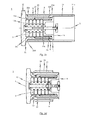
- Fig. 1 is an exemplary embodiment of a shock absorber 1 is shown in a perspective view.
- the exemplary embodiment is a crash buffer, which can be mounted, for example, on the front of a car body or on a stationary buffer bracket.
- the shock absorber 1 has a buffer ram 10 and a buffer housing 20.
- the buffer housing 20 facing the end portion of the buffer plunger 10 is received in the buffer housing 20 telescopically.
- Fig. 2a which shows the exemplary embodiment of the shock absorber 1 in a side view.
- the shock absorber is 1 in Fig. 2a shown in an unloaded state, ie in a state in which no pressure forces act on the buffer plunger 10.
- the buffer plunger 10 used in the exemplary embodiment of the shock absorber 1 consists in detail of a plunger sleeve 11, as shown in a perspective view in FIG Fig. 9 respectively. Fig. 10 is shown.
- the plunger sleeve 11 has a first end region 11a, on which a buffer plate 12 is attached, in particular welded.
- a first end region 11a of the plunger sleeve 11 opposite second end portion 11b of the plunger sleeve 11 is telescopically received in the assembled state of the shock absorber 1 in the buffer housing 20 of the shock absorber 1.
- the plunger sleeve 11 and the buffer housing 20 are arranged coaxially and concentrically with one another (cf. Fig. 2a ).
- the buffer case 20 is basically constituted by a buffer sleeve 21, a collet 22, and a deformation tube 23.
- the buffer sleeve 21 has a buffer end side first end portion 21a and a second end portion 21b opposite to the first end portion 21a.
- the buffer sleeve 21 is connected to a support structure, in particular with the front side of a car body, with the undercarriage of a car body or with a stationary buffer bracket.
- a flange arrangement 2 is provided on the second end region 21b of the buffer sleeve 21.
- the clamping sleeve 22 belonging to the buffer housing 20 has a buffer end side first end region 22a and a second end region 22b opposite the first end region 22a. Via the second end region 22b, the clamping sleeve 22 is connected to the first end region 21a of the buffer sleeve 21, as described below with regard to the first exemplary embodiment of the shock absorber 1 with reference to the illustrations in FIGS FIGS. 3a to 3d will be described in more detail.
- the exemplary embodiments of the shock absorber 1 have as a destructive energy dissipation element in each case a deformation tube 23 which - as in particular the exploded view according to Fig. 4 or the exploded view according to Fig. 6a can be removed - is designed as a cylindrical rotary member without any widening etc.
- the deformation tube 23 used as a destructive energy dissipation element is located between the first end region 22a of the clamping sleeve 22 and the clamped first end portion 21a of the buffer sleeve 21, as in particular the side sectional view according to Fig. 3a can be removed.
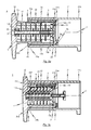
- Fig. 3a the exemplary embodiment of the shock absorber 1 shown in a side sectional view, wherein 10 no pressure forces are introduced into the buffer plate 12 of the buffer ram.
- the first exemplary embodiment of designed in the form of a crash buffer shock absorber 1 is designed to at least in a crash, ie when exceeding a introduced via the buffer plate 12 in the shock protection 1 pre-definable critical impact force, under plastic cross-sectional deformation of the deformation tube 23 to reduce part of the initiated impact energy and thus to consume.
- shock absorber 1 is designed to dampen tensile and impact forces before exceeding a initiated in the shock protection 1 critical impact force.
- the shock absorber 1 a regenerative damping device 3, which - as in the FIGS. 3a to 3d shown - can be designed as a spring pack.
- the damping device 3 is at least partially received in the plunger sleeve 11 and disposed between a connected to the plunger sleeve 11 first pressure plate 13a and connected to the buffer housing 20 second pressure plate 13b.
- the first pressure plate 13a is formed by the buffer plate 12, wherein the damping device 3 abuts a pointing in the direction of the buffer housing 20 surface of the buffer plate 12.
- the second pressure plate 13b is connected in the exemplary embodiment of the shock absorber 1 with the second end portion 22b of the clamping sleeve 22.
- a stop 25 connected to the clamping sleeve 22.
- This stop 25 has a pointing in the direction of the buffer plate 12 first stop surface 25a, which ultimately limits the longitudinal displacement of the buffer plunger 10 relative to the buffer housing 20 in the direction of the buffer sleeve 21.
- the clamping sleeve 22 associated stop 25 is preferably an annular circumferential stop.
- the exemplary embodiment of the shock protection 1 shown in the drawings with a special guide for guiding the longitudinal displacement of the buffer ram 10 is relative provided to the buffer housing 20.
- the guide for guiding the longitudinal displacement of the buffer plunger 10 relative to the buffer housing 20 at least one in the longitudinal direction L of the plunger sleeve 11 (or in the longitudinal direction L of the buffer housing 20) extending guide groove 4. In this at least one guide groove 4 engages a corresponding pin or guide pin 5 a.
- the guide pin 5 used for guiding the longitudinal displacement of the buffer plunger 10 relative to the buffer housing 20 in the exemplary embodiment of the shock absorber 1 is shown in a perspective view in FIG Fig. 13 shown.
- Fig. 11 shows a perspective view of the clamping sleeve 22 of the buffer housing 20 of the exemplary embodiment of the shock absorber 1
- Fig. 12 a side sectional view of the clamping sleeve 22 shows.
- Guide pin 5 are held in elongated receptacles 26 which are formed in the inner circumferential surface of the clamping sleeve 22 (see. Fig. 12 ).
- the pins / guide pins 5 are inserted through corresponding pin openings 5 'at the second end portion 22b of the clamping sleeve 22.
- the engaging in the corresponding guide groove 4 of the plunger sleeve 11 pin / guide pin 5 is connected to the second end portion 22b of the clamping sleeve 22 with the clamping sleeve 22.
- the pin / guide pin 5 is held partially in the assembled state of the shock absorber 1 in a corresponding in the clamping sleeve 22, and in detail provided in the inner circumferential surface of the clamping sleeve 22 elongated receptacle 26.
- the second end portion 22b of the clamping sleeve 22, with which the respective pins / guide pins 5 are connected, is at least partially telescopically received in the first end portion 21a of the buffer sleeve 21 and abuts in the direction of the buffer sleeve 21 against a bufferteller workede stop surface 6a of a first inside the first end portion 21a of the buffer sleeve 21 provided stop 6 of the buffer sleeve 21.
- This connected to the buffer sleeve 21 first stop 6 is preferably annular.
- a counter element 14 is also provided in the exemplary embodiment of the shock absorber 1.
- the counter element 14 is shown in the illustrations in the FIGS. 3a to 3d with the second pressure plate 13b, against which the recorded in the shock absorber 1 damping device 3 abuts connected.
- the counter element 14 accommodated in the interior of the buffer sleeve 21 abuts against a stop surface 6b of the first stop 6 facing the buffer plate side abutment 6.
- the counter element 14 abuts against a stop surface 7a of a second inside the first end region 21a and the buffer sleeve 21 Stop 7 of the buffer sleeve 21.
- first stop 6 of the second sleeve 7 connected to the buffer sleeve 21 is preferably annular.
- the counter element 14 is connected by means of screws 8 with the second end portion 22b of the clamping sleeve 22, in such a way that the first stop 6 of the buffer sleeve 21 is received between the clamping sleeve 22 and the counter element 14.
- a single common Stop to use as in the second exemplary embodiment of the solution according to the invention as shown in the FIGS. 5a to 5d the case is.
- the first stopper 6 connected to the buffer sleeve 21 is formed in the exemplary embodiment of the shock absorber 1 such that it shears off at a predetermined above the buffer plate 12 introduced into the shock protection 1 pre-definable critical impact force and thus its connection with the buffer sleeve 21 loses.
- the clamping sleeve 22 is then displaceable relative to the buffer sleeve 21 in the direction of the buffer sleeve 21.
- FIG. 3a in a side sectional view formed in the form of a crash buffer shock protection 1 in the unloaded state, ie in a state in which no pressure forces on the buffer plate 12 are introduced into the shock absorber 1.
- the buffer plunger 10 In this unloaded state, the buffer plunger 10 is in its maximum extended state, ie in a state in which the buffer plate 12 is farthest from the buffer housing 10.
- This in Fig. 3a shown state is the ground state of the shock absorber 1, which is taken independently of the shock absorber 1 when no pressure forces are introduced into the buffer plate 12.
- This basic state is predetermined by the damping device 3 provided in the interior of the shock absorber 1 and biased between the first pressure plate 13a (here buffer plate 12) and the second pressure plate 13b.
- Fig. 3b is a side view of the exemplary embodiment of the shock absorber 1 after exhaustion of the damping behavior of the shock absorber 1 integrated damping device 3 is shown.
- the shock absorber 1 can absorb or reduce any further impact forces in a regenerative manner.
- the destructively designed energy dissipation element responds to the shock absorber 1.
- a preferably cylindrically symmetric deformation tube 23 is used, which can be designed in particular as a rotating part without necessary expansions.
- the deformation tube 23 is arranged, in particular clamped, between the first end region 22a of the clamping sleeve 22 and the first end region 21a of the buffer sleeve 21 of the buffer housing 20.
- the stopper 25 formed on the first end portion 22a of the collet 22 is used, which has an opposed, i.e., in opposition to, the first abutment surface 25a for limiting the longitudinal displacement travel of the buffer plunger 10 relative to the buffer housing 20. in the direction of buffer sleeve 21 facing, second stop surface 25b. Against this second abutment surface 25 b abuts the bufferteller workede end portion of the clamped between the clamping sleeve 22 and the buffer sleeve 21 deformation tube 23rd
- the first stop 6 is in the exemplary embodiment of the shock absorber according to the invention designed as shearing element, which shears when exceeding a pre-definable critical impact force and solves the connection of the clamping sleeve 22 to the buffer sleeve 21. This condition is in Fig. 3c shown.
- the direct power transmission is interrupted by the clamping sleeve 22 to the buffer sleeve 21 via the first stop 6, the resulting impact energy over the stop 25 of the clamping sleeve 22 in the deformation tube 23 and from there into the first end portion 21a of the buffer sleeve 21 initiated.
- the deformation tube is plastically deformed, in particular when the buffer ram 10 is displaced with the clamping sleeve 22 in the direction of the buffer sleeve 21.
- a conical-ring-shaped region 24 is provided at the first end region of the buffer sleeve 21 in order to support the plastic cross-sectional widening of the deformation tube 23, and in particular to prevent tilting of components when the shock absorber 1 responds.
- the buffer sleeve 21 has a cylindrical outer circumferential surface 28, which is designed to guide a plastically expanded region of the deformation tube 23 with a longitudinal displacement of the deformation tube 23 relative to the buffer sleeve 21 after exceeding the pre-definable critical impact force.
- FIGS. 5a to 5d Side sectional views of a second exemplary embodiment of the shock absorber 1 are shown in different states of shock protection.
- Fig. 5a the second embodiment of the shock absorber 1 according to the invention shown in a side sectional view, wherein 10 no pressure forces are introduced into the buffer plate 12 of the buffer plunger.
- the buffer plunger 10 In this unloaded state, the buffer plunger 10 is in its maximum extended state, ie in a state in which the buffer plate 12 is farthest from the buffer housing 10.
- This in Fig. 5a shown state is the Basic state of the shock absorber 1, which is taken independently of the shock protection 1 when no pressure forces are introduced into the buffer plate 12.
- This basic state is predetermined by the damping device 3 provided in the interior of the shock absorber 1 and biased between the first pressure plate 13a (here buffer plate 12) and the second pressure plate 13b.
- Fig. 5b is a side view of the second embodiment of the shock absorber 1 according to the invention after exhaustion of the damping behavior of the shock absorber 1 integrated damping device 3 is shown.
- the shock absorber 1 can absorb or reduce any further impact forces in a regenerative manner.
- the destructively designed energy dissipation element responds to the shock absorber 1.
- a preferably cylindrically symmetric deformation tube 23 is used, which can be designed in particular as a rotating part without necessary expansions.
- the deformation tube 23 is arranged, in particular clamped, between the first end region 22a of the clamping sleeve 22 and the first end region 21a of the buffer sleeve 21 of the buffer housing 20.
- first end portion 22a of the clamping sleeve 22nd trained stop 25 is used, in addition to the first stop surface 25a, which serves to limit the L Lucassverschiebungsweges the buffer plunger 10 relative to the buffer housing 20, an opposite, ie in the direction of the buffer sleeve 21 facing, second stop surface 25b.
- second abutment surface 25 b abuts the bufferteller workede end portion of the clamped between the clamping sleeve 22 and the buffer sleeve 21 deformation tube 23rd
- the first stop 6 is designed as a shearing element, which shears off when a critical impact force that can be predetermined is exceeded and releases the connection of the clamping sleeve 22 to the buffer sleeve 21. This condition is in Fig. 5c shown.
- the direct power transmission is interrupted by the clamping sleeve 22 to the buffer sleeve 21 via the first stop 6, the resulting impact energy over the stop 25 of the clamping sleeve 22 in the deformation tube 23 and from there into the first end portion 21a of the buffer sleeve 21 initiated.
- the deformation tube is plastically deformed, in particular when the buffer ram 10 is displaced with the clamping sleeve 22 in the direction of the buffer sleeve 21.
- a conical-ring-shaped region 24 is provided at the first end region of the buffer sleeve 21 in order to support the plastic cross-sectional widening of the deformation tube 23, and in particular to prevent tilting of components when the shock absorber 1 responds.
- the buffer sleeve 21 has a cylindrical outer circumferential surface 28, which is designed to guide a plastically expanded region of the deformation tube 23 with a longitudinal displacement of the deformation tube 23 relative to the buffer sleeve 21 after exceeding the pre-definable critical impact force.
- FIG. 2 The structure and functioning of the in the FIGS. 5a to 5d
- the second exemplary embodiment shown in FIG. 2 essentially corresponds to the construction and the mode of operation of the previously described with reference to the illustrations in FIGS FIGS. 3a to 3d described first exemplary embodiment. In order to avoid repetition, only the differences between the two embodiments will be discussed briefly below:
- FIGS. 5a to 5d illustrated second exemplary embodiment of the shock absorber 1 according to the invention of the first embodiment according to the FIGS. 3a to 3d in that now only a single annular stop 6 is used, instead of two separate stops 6, 7 as in the first embodiment.
- the counter element 14 has a slightly modified configuration, which will be described below with reference to the illustrations in FIGS. 6a, 6b . 7a, 7b and 8a, 8b will be described in more detail.
- Fig. 6a in a perspective view, a first assembly step
- Fig. 6b in a side sectional view illustrating the shock absorber 1 after performing the first assembly step.
- the plunger sleeve 11 is first provided with the buffer plate 12 connected to the first end region 11a.
- the representation in Fig. 6a It can also be seen that in the outer circumferential surface of the plunger sleeve 11 already in the longitudinal direction L of the shock protection 1 extending guide grooves 4 are introduced.
- the damping device 3 which is formed in the exemplary embodiment as a spring assembly consisting of a plurality of coaxially and concentrically aligned spring plates, received in the interior of the plunger sleeve 11.
- a guide rod 30 is used, which is inserted into the plunger sleeve 11 and locked there accordingly.
- a securing piece 31 is to be introduced via the guide rod 30 into the plunger sleeve 11.
- the securing piece 31 is used for fixing the guide rod 30 in the interior of the plunger sleeve 11 such that the guide rod 30 is located on the longitudinal axis L of the shock absorber 1.
- a clamping sleeve 32 is attached to the exposed end portion of the guide rod 30 to the damping device 3 against the first pressure plate 13 a (the inside Side wall of the buffer plate 12).
- This condition is in Fig. 6b shown in a side sectional view of the shock protection 1.
- the protruding from the second end portion 11b of the plunger sleeve 11 part of the damping device 3 and attached to the guide rod 30 clamping sleeve 32 is - as soon as the second End portion 11b of the plunger sleeve 11 is telescopically received by the clamping sleeve 22 together with the inside of the plunger sleeve 11 at least partially absorbed damping device 3 - fixed by means of screws 33 to a second end portion 22b of the clamping sleeve 22 flange plate 34.
- the buffer sleeve 21 is then mounted together with the destructive energy dissipation element (deformation tube 23).
- the guide pin 5 are first introduced in the third assembly step from behind through the flange plate 34 in the elongated receptacles 26 which are formed in the clamping sleeve 22.
- corresponding pin openings 5 ' are formed in the flange plate 34.
- the guide pin 5 partially in the elongated receptacles 26, while a part of the guide pin 5 engages in the guide groove 4 of the plunger sleeve 11 like a rail.
- the destructive energy dissipation element formed in particular in the form of a deformation tube 23 from the rear, i. Slid over the second end portion 22b of the clamping sleeve 22 on the clamping sleeve 22 until the deformation tube 23 abuts the second stop surface 25b of the first end portion 22a of the clamping sleeve 22 provided stop 25.
- the composite is connected to the first end portion 21 a of the buffer sleeve 21.
- a plate-shaped counter element 14 is used, which is inserted from behind into the buffer sleeve 21, until it abuts against the second provided in the interior of the first end portion 21a of the buffer sleeve 21 annular stop 7 of the buffer sleeve 21.
- the counter element 14 is connected by means of screws 8 with the second end portion 22b of the clamping sleeve 22 such that the first stop 6 of the buffer sleeve 21 is received between the clamping sleeve 22 and the counter element 14.
- FIGS. 15 to 27 the structure and operation of an exemplary embodiment of the shock absorber 1 according to the invention described.
- FIG. 15 in a perspective view of the exemplary embodiment of the shock absorber 1 according to the invention.
- a side view of the exemplary embodiment is shown in FIG Fig. 16a shown, in an unloaded state of the shock absorber 1, ie in a state in which no pressure forces acting on the buffer plunger 10 of the shock absorber 1.
- the exemplary embodiment of the shock absorber 1 also has a buffer ram 10 and a buffer housing 20.
- the buffer housing 20 facing the end portion of the buffer plunger 10 is received in the buffer housing 20 telescopically.
- the buffer plunger 10 consists essentially of a plunger sleeve 11, as in a perspective view in Fig. 23 is shown.
- the ram sleeve 11 used in the exemplary embodiment of the shock absorber 1 is designed as a circular-cylindrical body, which has a substantial outer diameter from the first end portion 11a of the ram sleeve 11 to the opposite second end portion 11b of the ram sleeve 11.
- the plunger sleeve 11 In contrast to the plunger sleeve, which is used in the first and second exemplary embodiment of the shock absorber 1, in the plunger sleeve 11 according to the exemplary embodiment of the inventive solution, in particular the first end portion 11a of the plunger sleeve 11 is not expanded. In this way, when a critical impact force is introduced into the buffer tappet 10, an (unwanted) deformation of the tappet sleeve 11 can be effectively prevented.
- the end face of the first end portion 11a of the plunger sleeve 11 is wedge-shaped.
- the buffer plate 12 is provided a complementary to the wedge-shaped end face formed groove to receive the first end portion 11 a of the plunger sleeve 11.
- the structure of the shock absorber 1 according to the exemplary embodiment of the shock absorber 1 according to the invention substantially corresponds to the structure of the first and second exemplary embodiments described above. To avoid repetition, reference is therefore made to the previous statements.
- a further (fourth) assembly step in the Figs. 21a and 21b is shown.
- a response indicator 35 is attached to the already mounted shock absorber 1, which is designed to indicate whether the deformation tube 23 integrated in the shock absorber 1 has possibly already been mentioned.
- the response indicator 35 is formed as a sheet-metal strip at the transition point between the deformation tube 23 and the buffer sleeve 21. As soon as the deformation tube 23 has also pushed on the buffer sleeve 21 only slightly, this is indicated on the basis of the response indicator 35, since it deforms or flakes off accordingly.
- a difference is to be seen in the fact that in Fig. 24 illustrated clamping sleeve 22, which is used in the exemplary embodiment of the shock absorber 1 according to the invention, the pin openings 5 'in comparison to the illustration in Fig. 11 are arranged rotated.
- the invention is not limited to the exemplified embodiment of the crash buffer designed as crash buffer, but results from a synopsis of all features disclosed herein.
- the shock absorber 1 according to the invention is provided with a response indicator 35 to indicate whether the integrated in the shock absorber 1 deformation tube 23 has possibly already addressed.
- the response indicator 35 is formed as a sheet-metal strip at the transition point between the deformation tube 23 and the buffer sleeve 21. As soon as the deformation tube 23 only partially on the buffer sleeve 21 has pushed, this is indicated by the response indicator 35, since this deforms accordingly or flakes off.
- the individual components of the shock absorber 1 are formed from materials which are optimized in terms of weight.
- the buffer sleeve 21, the deformation tube 23, the clamping sleeve 22 and / or the plunger sleeve 11 are formed from a lightweight material / is.
- a lightweight material is in particular aluminum, an aluminum alloy or a fiber composite material in question. It is of course conceivable that the aforementioned components of the shock absorber 1 from different materials (in particular lightweight materials) are formed.
Abstract
Description
Die vorliegende Erfindung betrifft eine Stoßsicherung, insbesondere in Gestalt eines Crashpuffers, wobei die Stoßsicherung einen Pufferstößel mit einer Stößelhülse und einem an einem ersten Endbereich der Stößelhülse angeordneten Pufferteller sowie ein Puffergehäuse aufweist, in welchem zumindest ein dem ersten Endbereich der Stößelhülse gegenüberliegender zweiter Endbereich der Stößelhülse teleskopartig aufgenommen ist.The present invention relates to a shock absorber, in particular in the form of a crash buffer, wherein the shock absorber comprises a buffer plunger with a plunger sleeve and a buffer arranged at a first end portion of the plunger sleeve and a buffer housing, in which at least one of the first end portion of the plunger sleeve opposite second end portion of the plunger sleeve is recorded telescopically.
Es ist bekannt, zum Schutz vor Beschädigungen an der Außenhaut eines Schiffes bei Hafenmanövern sowie beim Liegen an einer Kaimauer sogenannte Fender einzusetzen. Üblicherweise wird dabei der als Schutzkörper fungierende Fender so zwischen dem Schiff und der Kaimauer positioniert, dass er einerseits als Stoßdämpfer und andererseits als Abstandshalter dient, damit der Schiffsrumpf nicht scheuert. Für größere Schiffe werden in der Regel eigenständig gegründete Fender verwendet, die Bestandteil einer Kaianlage sind. Derartige als Bestandteil einer Kaianlage ausgeführte Fender können bis zu einem gewissen Grad elastisch ausgeführt sein, damit diese bis zu einem gewissen Maß auch die Schiffsbewegungen beim Anlegen und bei Wellengang mitmachen können.It is known to use so-called Fender to protect against damage to the outer skin of a ship during port maneuvers and when lying on a quay wall. Usually, the fender functioning as a protective body is positioned between the ship and the quay wall in such a way that it serves as a shock absorber on the one hand and as a spacer on the other hand so that the hull does not rub. For larger vessels, independently established fenders are usually used, which are part of a quay. Such fenders implemented as part of a quay can be elastic to a certain extent, so that they can, to a certain extent, also participate in the ship movements during docking and in waves.
Bei Überschreiten des elastischen Dämpfungsvermögens der zum Einsatz kommenden Fender besteht allerdings die Gefahr der Beschädigung der Außenhaut des Schiffes, da die beispielsweise bei einem ungebremsten Anstoßen des Schiffes an eine Kaimauer auftretende Stoßenergie ungedämpft auf die Außenhaut des Schiffes wirkt. Um bei diesem Szenario eine Beschädigung der Außenhaut des Schiffes zu vermeiden, ist es denkbar, eine irreversibel ausgeführte Stoßsicherung insbesondere in Gestalt eines Crashpuffers vorzusehen, die beim Überschreiten des Dämpfungsvermögens der zum Einsatz kommenden Fender anspricht und dann zumindest einen Teil der auftretenden Stoßenergie absorbiert bzw. in Verformungsarbeit und Wärme umwandelt.When the elastic damping capacity of the fender used is exceeded, however, there is a risk of damaging the outer skin of the ship, since the impact energy occurring, for example, in the case of an unrestrained impact of the vessel on a quay wall, is not dampened on the outer skin of the ship Ship acts. In order to avoid damage to the outer skin of the ship in this scenario, it is conceivable to provide an irreversibly designed shock protection, in particular in the form of a crash buffer, which responds when exceeding the damping capacity of the Fender used for use and then absorbs at least part of the impact energy occurring or transformed into deformation work and heat.
Allgemein ist das Abdämpfen von Stoßkräften und der wirksame Verzerr von bei einem Aufprall entstehender Stoßenergie insbesondere bei einem sich bewegenden Objekt ein Problem, wenn aufgrund der Masse des Objekts hohe Bewegungsenergien zu berücksichtigen sind, die nach einem vorhersehbaren Ereignisablauf in definierter Weise zu absorbieren sind.In general, the damping of impact forces and the effective distortion of impact energy arising in an impact, especially in a moving object is a problem when due to the mass of the object high movement energies are to be considered, which are to be absorbed after a predictable event in a defined manner.
Dies betrifft nicht nur Schiffe, wie etwa Öltanker, für die als Bestandteil einer Kaianlage eine Stoßsicherung vorzusehen ist, sondern auch Schienenfahrzeuge. Aus der Bahntechnik sind beispielsweise Prellböcke bekannt, die dem Abschluss eines Gleises bzw. Stumpfgleises einer Eisenbahnstrecke dienen und verhindern sollen, dass ein Schienenfahrzeug oder ein Waggon über das Schienenende hinaus rollen kann. Prellböcke sind meist so beschaffen, dass möglichst viel Energie des sich bewegenden Schienenfahrzeuges aufgenommen werden kann, damit das Schienenfahrzeug nach Möglichkeit unbeschädigt bleibt. Der Prellbock kann dabei unter Umständen verformt oder zerstört werden.This does not only apply to ships, such as oil tankers, for which a shock absorber is to be provided as part of a quay, but also rail vehicles. For example, bumpers are known from railway technology, which are used to complete a track or stump track of a railway track and to prevent a rail vehicle or a wagon from rolling beyond the end of the rail. Bumpers are usually designed so that as much energy of the moving rail vehicle can be absorbed so that the rail vehicle remains undamaged if possible. Under certain circumstances, the buffer can be deformed or destroyed.
Stoßsicherungen kommen aber auch in Gestalt von Stoßfängern zum Einsatz. Hierbei handelt es sich um Bauelemente an Fahrzeugen, die im Falle eines Zusammenstoßes oder eines Aufpralls auf ein festes Hindernis Energie aufnehmen und dadurch Beschädigungen am Fahrzeug oder der Ladung verhindern sollen. Stoßfänger kommen vor allem an Schienenfahrzeugen (auch als "Puffer", "Buffer" oder "Stoßballen" bezeichnet) vor, wobei meistens ein oder zwei an den Stirnseiten angebrachte Konstruktionsteile eingesetzt werden, die den Zweck haben, die auf das Schienenfahrzeug in dessen Längsrichtung von außen her einwirkenden waagrechten Druckkräfte aufzunehmen. Dem Prinzip nach können bei Schienenfahrzeugen als Stoßsicherung zwei Arten von Stoßfängern zum Einsatz kommen, nämlich sogenannte "Einpuffer" oder "Zentralpuffer", bei denen die Stoßsicherung in der Längsachse des Fahrzeuges angebracht ist, so dass sich an jeder Stirnseite des Schienenfahrzeuges nur ein Puffer in der Mitte der Kopfschwelle befindet, oder sogenannte "Zweipuffer" oder "Seitenpuffer", bei welchen sich zwei Puffer an der Stirnseite des Schienenfahrzeuges befinden.But shock absorbers are also used in the form of bumpers. These are components on vehicles which, in the event of a collision or an impact on a fixed obstacle, absorb energy and thereby prevent damage to the vehicle or the cargo. Bumpers are mainly used on rail vehicles (also referred to as "buffers", "buffers" or "bumps"), wherein usually one or two attached to the front end construction parts are used, which have the purpose on the rail vehicle in the longitudinal direction of externally acting horizontal compressive forces absorb. In principle, two types of bumpers can be used in rail vehicles as a shock absorber, namely so-called "buffer" or "central buffer" in which the shock absorber is mounted in the longitudinal axis of the vehicle, so that at each end of the rail vehicle only a buffer in the middle of the head threshold, or so-called "two-buffer" or "side buffer", in which two buffers are located on the front side of the rail vehicle.
Demnach ist es aus dem Gebiet der Schienenfahrzeugtechnik bekannt, beispielsweise bei einem mehrgliedrigen Schienenfahrzeug die einzelnen Wagenkästen mit sogenannten Seitenpuffern oder UIC-Puffern auszurüsten, wenn die Wagenkästen nicht über ein Drehgestell miteinander verbunden sind und somit im Fahrbetrieb der Abstand zweier miteinander gekuppelter Wagenkästen variieren kann. Diese Seitenpuffer dienen dazu, die im normalen Fahrbetrieb beispielsweise beim Abbremsen oder Anfahren auftretenden Stöße aufzunehmen und abzudämpfen.Accordingly, it is known from the field of rail vehicle technology, for example, in a multi-unit rail vehicle to equip the individual car bodies with so-called side buffers or UIC buffers, if the car bodies are not connected to each other via a bogie and thus can vary the driving distance of two mutually coupled car bodies. These page buffers are used to absorb and dampen the shocks occurring during normal driving, for example when braking or starting.
Für Seitenpuffer kommt in der Regel ein teleskopartiger Aufbau zum Einsatz, der ein Puffergehäuse, ein darin zumindest bereichsweise teleskopartig aufgenommenen Pufferstößel sowie ein Dämpfungselement in Gestalt einer Feder oder eines Elastomerkörpers aufweist. Bei einem derartigen Aufbau dient das Puffergehäuse als Längsführung und zur Abstützung von Querkräften, während das in dem Puffergehäuse aufgenommene Dämpfungselement zur Kraftübertragung in Längsrichtung dient.For side buffer is usually a telescopic structure is used, which has a buffer housing, a therein at least partially telescopically recorded buffer plunger and a damping element in the form of a spring or an elastomer body. With such a construction, the buffer housing serves as a longitudinal guide and for supporting transverse forces, while the damping element accommodated in the buffer housing serves to transmit power in the longitudinal direction.
Die Baulänge sowie der Pufferhub, d.h. der Federweg des in dem Puffergehäuse aufgenommenen Dämpfungselements, definiert die Dämpfungseigenschaft des Seitenpuffers. Nach Erreichen des maximalen Pufferhubs ist die Dämpfungseigenschaft des Seitenpuffers ausgeschöpft, infolgedessen die über die charakteristische Betriebslast des Seitenpuffers hinausgehenden Stoßkräfte ungedämpft in das Fahrzeuguntergestell weitergeleitet werden.The length and the buffer stroke, i. the spring travel of the damping element accommodated in the buffer housing defines the damping property of the side buffer. After reaching the maximum buffer stroke, the damping characteristic of the page buffer is exhausted, as a result of which the shock forces beyond the characteristic operating load of the side buffer are passed on undamped into the vehicle undercarriage.
Dadurch werden zwar Stoßkräfte, die während des normalen Fahrbetriebs beispielsweise bei einem mehrgliedrigen Fahrzeug zwischen den einzelnen Wagenkästen auftreten, über das in dem Seitenpuffer integrierte, regenerativ ausgebildete Dämpfungselement absorbiert; bei Überschreiten der Betriebslast des Seitenpuffers hingegen, etwa beim Aufprall des Fahrzeuges auf ein Hindernis oder bei einem abrupten Abbremsen des Fahrzeuges, reicht üblicherweise das in dem Seitenpuffer integrierte Dämpfungselement nicht für einen Verzehr bzw. Abdämpfung der insgesamt anfallenden Energie aus. Dadurch ist die von dem Seitenpuffer bereitgestellte Stoßdämpfung nicht mehr in dem Energieverzehrkonzept des Gesamtfahrzeuges eingebunden, so dass dann die anfallende Stoßenergie direkt auf das Fahrzeuguntergestell übertragen wird. Dieses wird dabei extremen Belastungen ausgesetzt und unter Umständen beschädigt oder gar zerstört.As a result, although impact forces which occur during normal driving operation, for example in a multi-unit vehicle between the individual car bodies, are absorbed via the regeneratively formed damping element integrated in the side buffer; on the other hand, when the operating load of the side buffer is exceeded, for example when the vehicle strikes an obstacle or during an abrupt deceleration of the vehicle, the damping element integrated in the side buffer usually does not suffice for consumption or damping of the total energy produced. As a result, the shock absorption provided by the side buffer is no longer involved in the energy consumption concept of the entire vehicle, so that then the resulting impact energy directly is transferred to the vehicle undercarriage. This is exposed to extreme loads and may be damaged or even destroyed.
Mit dem Ziel, derartige Schäden zu vermeiden, ist es aus der Schienefahrzeugtechnik bereits bekannt, dem Seitenpuffer bzw. dem regenerativ ausgebildeten Dämpfungselement des Seitenpuffers ein destruktiv ausgebildetes Energieverzehrelement nachzuschalten, welches nach Ausschöpfung des maximalen Pufferhubs anspricht und durch plastische Deformation zusätzlich Stoßenergie abbaut und somit verzehrt.With the aim of avoiding such damage, it is already known from rail vehicle technology to connect a destructively designed energy absorbing element to the side buffer or the regeneratively designed damping element of the side buffer, which responds after exhausting the maximum buffer stroke and additionally degrades impact energy by plastic deformation and thus consumes it ,
So wird beispielsweise in der Druckschrift
Andererseits ist aus der Druckschrift
Die aus dem Stand der Technik bekannten Lösungen haben den Nachteil, dass - sofern ein UIC-Puffer bzw. Seitenpuffer mit einer zusätzlichen irreversiblen Stoßsicherungsstufe versehen sein soll - die Baugröße des UIC-Puffers bzw. Seitenpuffers erheblich vergrößert wird.The known from the prior art solutions have the disadvantage that - if a UIC buffer or page buffer should be provided with an additional irreversible shock protection level - the size of the UIC buffer or page buffer is significantly increased.
Der vorliegenden Erfindung liegt die Aufgabe zugrunde, eine Stoßsicherung bereitzustellen, welche sich durch eine kompakte Bauweise mit einem hohen Energieverzehr auszeichnet, wobei die kompakte Bauweise auch dann realisierbar ist, wenn die Stoßsicherung in Kombination mit einer regenerativ ausgebildeten Dämpfungseinrichtung zum Einsatz kommt.The present invention has for its object to provide a shock absorber, which is characterized by a compact design with a high energy consumption, the compact design is also feasible when the shock absorber is used in combination with a regenerative damping device.
Diese Aufgabe wird durch den Gegenstand des unabhängigen Patentanspruches 1 gelöst.This object is solved by the subject matter of
Demgemäß betrifft die Erfindung insbesondere eine Stoßsicherung in Gestalt eines Crashpuffers, wobei die Stoßsicherung einen Pufferstößel mit einer Stößelhülse und einem an einem ersten Endbereich der Stößelhülse angeordneten Pufferteller aufweist. Des Weiteren gehört ein Puffergehäuse zu der Stoßsicherung, in welchem zumindest ein dem ersten Endbereich der Stößelhülse gegenüberliegender zweiter Endbereich der Stößelhülse teleskopartig aufgenommen ist. Erfindungsgemäß weist das Puffergehäuse eine Pufferhülse mit einem puffertellerseitigen Endbereich und einem dem puffertellerseitigen ersten Endbereich gegenüberliegenden zweiten Endbereich auf. Über den zweiten Endbereich der Pufferhülse ist die Pufferhülse und somit die insbesondere in Gestalt eines Crashpuffers ausgeführte Stoßsicherung, mit einer zu schützenden Tragstruktur verbindbar. Hierbei kann es sich beispielsweise um die Stirnseite eines Wagenkastens, um ein Untergestell eines Wagenkastens, um einen ortsfesten Pufferbock oder beispielsweise um eine Kaianlage bzw. Teil einer Kaimauer handeln.Accordingly, the invention particularly relates to a shock absorber in the form of a crash buffer, wherein the shock absorber has a buffer plunger with a plunger sleeve and a buffer plate arranged on a first end region of the plunger sleeve. Furthermore, a buffer housing belongs to the shock absorber in which at least one second end region of the plunger sleeve opposite the first end region of the plunger sleeve is accommodated telescopically. According to the invention, the buffer housing has a buffer sleeve with a buffer-plate-side end region and a second end region opposite the buffer-plate-side first end region. Via the second end region of the buffer sleeve, the buffer sleeve and thus the shock absorber, in particular in the form of a crash buffer, can be connected to a support structure to be protected. This may be, for example, the front side of a car body, a subframe of a car body, a stationary buffer block or, for example, a quay or part of a quay wall.
Nach der erfindungsgemäßen Lösung weist das Puffergehäuse ferner eine Spannhülse mit einem puffertellerseitigen ersten Endbereich und einem dem puffertellerseitigen ersten Endbereich gegenüberliegenden zweiten Endbereich auf. Über den zweiten Endbereich der Spannhülse ist die Spannhülse mit dem ersten Endbereich der Pufferhülse des Puffergehäuses verbunden. Diese Verbindung ist so ausgeführt, dass diese sich bei Überschreiten einer in die Stoßsicherung eingeleiteten vorab festlegbaren (kritischen) Stoßkraft selbstständig löst, um eine Längsverschiebung der Spannhülse relativ zu der Pufferhülse in Richtung der Pufferhülse zu ermöglichen.According to the solution according to the invention, the buffer housing further has a clamping sleeve with a buffer end side first end region and a second end region opposite the buffer end side first end region. About the second end portion of the clamping sleeve, the clamping sleeve is connected to the first end portion of the buffer sleeve of the buffer housing. This compound is designed so that it automatically solves when a previously introduced in the shock protection pre-definable (critical) impact force to a longitudinal displacement allow the clamping sleeve relative to the buffer sleeve in the direction of the buffer sleeve.
Um in einem Crashfall die in die Stoßsicherung über einen Stoß eingeleitete Energie zumindest teilweise abbauen zu können, ist bei der erfindungsgemäßen Stoßsicherung vorgesehen, dass das Puffergehäuse ferner ein destruktives Energieverzehrelement aufweist, welches insbesondere in Gestalt eines Verformungsrohres ausgeführt ist. Das Energieverzehrelement ist zwischen dem ersten Endbereich der Spannhülse und dem ersten Endbereich der Pufferhülse eingespannt. Dabei ist vorgesehen, dass bei Überschreiten einer über den Pufferteller in die Stoßsicherung eingeleiteten vorab festlegbaren kritischen Stoßkraft die Verbindung zwischen dem zweiten Endbereich der Spannhülse und dem ersten Endbereich der Pufferhülse gelöst und die Spannhülse zusammen mit dem insbesondere als Verformungsrohr ausgebildeten destruktiven Energieverzehrelement unter gleichzeitiger plastischer Verformung des Energieverzehrelements relativ zu der Pufferhülse in Richtung Pufferhülse verschoben wird.In order to be able to at least partially reduce the energy introduced into the shock absorber in the event of a crash, it is provided in the shock absorber according to the invention that the buffer housing further has a destructive energy dissipation element, which is designed in particular in the form of a deformation tube. The energy dissipation element is clamped between the first end region of the clamping sleeve and the first end region of the buffer sleeve. It is envisaged that when exceeding a introduced via the buffer plate in the shock protection pre-definable critical impact force solved the connection between the second end of the clamping sleeve and the first end of the buffer sleeve and the clamping sleeve together with the particular designed as a deformation destructive energy absorbing element with simultaneous plastic deformation of the energy absorbing element is displaced relative to the buffer sleeve in the direction of the buffer sleeve.
Um die Funktionsfähigkeit der Stoßsicherung zu verbessern, und um insbesondere zu verhindern, dass es bei Überschreiten einer über den Pufferteller in die Stoßsicherung eingeleiteten kritischen Stoßkraft zu einer (ungewollten) Verformung der Stößelhülse kommen kann, ist bei der erfindungsgemäßen Lösung insbesondere vorgesehen, dass die Stößelhülse als kreiszylindrischer Körper ausgebildet ist, und zwar deart, dass die Stößelhülse von ihrem ersten Endbereich zu ihrem gegenüberliegenden zweiten Endbereich einen wesentlichen konstanten Außendurchmesser aufweist. Mit dieser konstruktiv leicht realisierbaren Weise kann wirkungsvoll verhindert werden, dass beim Einleiten einer kritischen Stoßkraft in die Stoßsicherung eine (ungewollte) Verformung der Stößelhülse auftritt.In order to improve the functionality of the shock absorber, and in particular to prevent that it may occur when exceeding a buffer pad in the shock protection critical impact force to an (unwanted) deformation of the plunger sleeve is provided in the inventive solution in particular that the plunger sleeve is formed as a circular cylindrical body, namely deart that the plunger sleeve has a substantially constant outer diameter from its first end portion to its opposite second end portion. With this structurally easily realizable way can be effectively prevented that when introducing a critical impact force in the shock protection an (unwanted) deformation of the plunger sleeve occurs.
Die erfindungsgemäße Stoßsicherung zeichnet sich insbesondere durch den einzigartigen und vorstehend beschriebenen Aufbau des Puffergehäuses aus, was eine kompakte Bauweise der Stoßsicherung auch dann gewährleistet, wenn zusätzlich zu dem destruktiven Energieverzehrelement eine regenerativ ausgebildete Dämpfungseinrichtung zum Einsatz kommt, mit welcher vor dem plastischen Verformen des destruktiven Energieverzehrelements in regenerativer Weise Zug-/Stoßkräfte abgedämpft werden.The shock absorber according to the invention is characterized in particular by the unique and above-described construction of the buffer housing, which also ensures a compact construction of the shock protection, if in addition to the destructive energy dissipation element a regenerative damping device is used, with which before the plastic deformation of the destructive energy dissipation element regenerative tensile / impact forces are damped.
Vorteilhafte Weiterbildungen der erfindungsgemäßen Lösung sind in den abhängigen Patentansprüchen angegeben.Advantageous developments of the solution according to the invention are specified in the dependent claims.
Gemäß einer vorteilhaften Weiterbildung der erfindungsgemäßen Stoßsicherung ist am ersten Endbereich der Pufferhülse ein kegelringförmiger Bereich vorgesehen, gegen den ein der Pufferhülse zugewandter Bereich des vorzugsweise als Verformungsrohr ausgebildeten Energieverzehrelements anstößt. Der kegelringförmige Bereich ist vorzugsweise derart ausgebildet, dass bei Überschreiten einer über den Pufferteller in die Stoßsicherung eingeleiteten vorab festlegbaren kritischen Stoßkraft das vorzugsweise als Verformungsrohr ausgebildete Energieverzehrelement unter plastischer Querschnittserweiterung über die Pufferhülse geschoben wird. Der kegelringförmige Bereich weist vorzugsweise eine in Richtung des als Verformungsrohr ausgebildeten Energieverzehrelements konisch zulaufende Mantelfläche auf. Durch das Vorsehen eines solchen kegelringförmigen Bereiches am ersten Endbereich der Pufferhülse, welcher entweder integral mit der Pufferhülse ausgebildet oder als einzelnes Bauelement zusätzlich zu der Pufferhülse vorgesehen sein kann, findet im Crashfall eine plastische Querschnittsaufweitung des als Verformungsrohr ausgebildeten Energieverzehrelements in einer vorab vorhersehbaren Weise statt, ohne dass dabei insbesondere ein Verkanten oder ein Verkeilen von Bauteilen der Stoßsicherung auftreten kann.According to an advantageous development of the shock absorber according to the invention, a conical-ring-shaped region is provided at the first end region of the buffer sleeve, against which a region of the buffer sleeve facing the energy dissipation element, preferably designed as a deformation tube, abuts. The conical-ring-shaped region is preferably designed such that, when a critical impact force introduced via the buffer plate into the shock protection is exceeded, the energy dissipation element, which is preferably designed as a deformation tube, is pushed over the buffer sleeve under plastic cross-sectional widening. The conical-ring-shaped region preferably has a conically tapered lateral surface in the direction of the energy dissipation element designed as a deformation tube. By providing such a conical-ring-shaped region at the first end region of the buffer sleeve, which can either be formed integrally with the buffer sleeve or provided as a single component in addition to the buffer sleeve, a plastic cross-sectional widening of the energy dissipation element formed as a deformation tube takes place in a predictable manner in the event of a crash. without in particular a tilting or wedging of components of the shock protection can occur.
Vorzugsweise weist die Pufferhülse des Puffergehäuses eine zylindrische Außenmantelfläche auf, so dass auf diese Weise eine Führung bereitgestellt wird, um beim Ansprechen des vorzugsweise als Verformungsrohr ausgebildeten Energieverzehrelements den plastisch aufgeweiteten Bereich des Energieverzehrelements bei einer Längsverschiebung dieses relativ zu der Pufferhülse zu führen. Durch das Vorsehen einer eine zylindrische Außenmantelfläche aufweisende Pufferhülse und vorzugsweise in Kombination mit einem kegelringförmigen Bereich am ersten Endbereich der Pufferhülse kann erreicht werden, dass beim Ansprechen der Stoßsicherung die Bewegung der Spannhülse zusammen mit dem Energieverzehrelement relativ zu der Pufferhülse in Richtung Pufferhülse nach einem vorab vorhersehbaren Ereignisablauf stattfindet, ohne dass die Gefahr besteht, dass ein Verkanten oder ein Verkeilen von Bauteilen der Stoßsicherung auftreten kann.Preferably, the buffer sleeve of the buffer housing has a cylindrical outer circumferential surface, so that in this way a guide is provided to guide the plastically expanded portion of the energy absorbing element in a longitudinal displacement of this relative to the buffer sleeve in response of the energy dissipation element preferably designed as a deformation tube. By providing a cylindrical outer circumferential surface having a buffer sleeve and preferably in combination with a conical-shaped portion at the first end portion of the buffer sleeve can be achieved that in response to the shock protection, the movement of the clamping sleeve together with the energy absorbing element relative to the buffer sleeve in the direction of buffer sleeve after a predictable in advance Event sequence takes place without the risk that jamming or wedging of components of the shock protection can occur.
Um zu erreichen, dass die Stoßsicherung nicht nur die in einem Crashfall anfallende Stoßenergie zumindest teilweise durch plastische Verformung des destruktiv ausgebildeten Energieverzehrelements abbauen kann, sondern auch die im normalen Fahrbetrieb auftretenden Stöße bzw. Zugkräfte abdämpfen kann, ist in einer bevorzugten Realisierung der erfindungsgemäßen Lösung vorgesehen, dass zumindest vor dem Überschreiten einer über den Pufferteller der Stoßsicherung in die Stoßsicherung eingeleiteten vorab festlegbaren kritischen Stoßkraft der Pufferstößel relativ zu dem Puffergehäuse in Richtung der Pufferhülse verschiebbar ist.In order to achieve that the shock absorber can not only reduce the impact energy generated in a crash case, at least partially by plastic deformation of the destructively designed energy dissipation element, but also in the normal Driving operation occurring shocks or tensile forces can dampen, is provided in a preferred realization of the solution according to the invention that at least before exceeding a introduced via the buffer plate of the shock absorber in the shock protection pre-definable critical impact force of the buffer ram relative to the buffer housing in the direction of the buffer sleeve is displaceable ,
Ein Längsverschiebungsweg, um den der Pufferstößel relativ zu dem Puffergehäuse in Richtung der Pufferhülse verschiebbar ist, lässt sich gemäß einem Aspekt der vorliegenden Erfindung dadurch definieren bzw. begrenzen, indem am ersten Endbereich der Spannhülse ein Anschlag, insbesondere ein ringförmig umlaufender Anschlag, mit einer puffertellerseitigen Anschlagfläche vorgesehen ist, wobei diese puffertellerseitige Anschlagfläche der Spannhülse den Längsverschiebungsweg des Pufferstößels relativ zu dem Puffergehäuse begrenzt.A Längsverschiebungsweg, by which the buffer plunger is displaceable relative to the buffer housing in the direction of the buffer sleeve can be defined or limited according to an aspect of the present invention by a stop, in particular an annular circumferential stop, with a buffertellerseitigen at the first end portion of the clamping sleeve Stop surface is provided, said bufferteller side stop surface of the clamping sleeve limits the longitudinal displacement travel of the buffer plunger relative to the buffer housing.
Bei den zuletzt genannten Ausführungsformen ist es insbesondere von Vorteil, wenn eine regenerativ ausgebildete Dämpfungseinrichtung vorgesehen ist, um die im normalen Fahrbetrieb auftretenden Zug- und Stoßkräfte in regenerativer Weise abdämpfen zu können. Vorzugsweise ist die beispielsweise in Gestalt eines Federapparates ausgebildete Dämpfungseinrichtung zumindest bereichsweise in der Stößelhülse aufgenommen und zwischen einer mit der Stößelhülse verbundenen ersten Druckplatte und einer mit dem Puffergehäuse verbundenen zweiten Druckplatte angeordnet. Die Integration der regenerativ ausgebildeten Dämpfungseinrichtung in den Komponenten des Puffergehäuses ermöglicht eine besonders kompakte Bauweise der Stoßsicherung, da für die Dämpfungseinrichtung bzw. das destruktiv ausgebildete Energieverzehrelement kein zusätzlicher Bauraum bereitgestellt werden muss.In the last-mentioned embodiments, it is particularly advantageous if a regenerative damping device is provided in order to be able to dampen the tensile and impact forces occurring in normal driving operation in a regenerative manner. Preferably, the damping device formed for example in the form of a spring apparatus is at least partially accommodated in the plunger sleeve and arranged between a first pressure plate connected to the plunger sleeve and a second pressure plate connected to the buffer housing. The integration of the regenerative damping device in the components of the buffer housing allows a particularly compact design of shock protection, since no additional space must be provided for the damping device or the destructively designed energy dissipation element.
In einer bevorzugten Weiterbildung der zuletzt genannten Ausführungsform, bei welcher die Stoßsicherung mit einer regenerativ ausgebildeten Dämpfungseinrichtung versehen ist, ist vorgesehen, dass die erste Druckplatte vorzugsweise durch den Pufferteller gebildet wird und die Dämpfungseinrichtung an eine in Richtung des Puffergehäuses zeigende Fläche des Puffertellers anstößt, wobei die zweite Druckplatte mit dem zweiten Endbereich der Spannhülse verbunden ist. Selbstverständlich sind in diesem Zusammenhang aber auch andere Ausführungsformen denkbar.In a preferred embodiment of the last-mentioned embodiment, in which the shock absorber is provided with a regenerative damping device, it is provided that the first pressure plate is preferably formed by the buffer plate and abuts the damping device to a pointing in the direction of the buffer housing surface of the buffer plate, said the second pressure plate is connected to the second end region of the clamping sleeve. Of course, other embodiments are conceivable in this context.
Die vorliegende Erfindung zeichnet sich nicht nur durch eine kompakte Bauweise der Stoßsicherung aus, sondern auch dadurch, dass eine Längsverschiebung des Pufferstößels relativ zu dem Puffergehäuse nach einem vorab festgelegten definierten Ereignisablauf stattfindet. Zu diesem Zweck ist gemäß einem Aspekt der vorliegenden Erfindung eine Führung vorgesehen, um die Längsverschiebung des Pufferstößels relativ zu dem Puffergehäuse zu führen. Um bei einer Bewegung des Pufferstößels relativ zu dem Puffergehäuse eine unerwünschte Kerbwirkung zwischen den Bauteilen der Stoßsicherung zu verhindern und um auf diese Weise auf eine unerwünschte Überdimensionierung der betreffenden Bauteile verzichten zu können, ist bei einer bevorzugten Weiterbildung der zuletzt genannten Ausführungsform vorgesehen, dass die Führung mindestens eine in Längsrichtung der Stößelhülse bzw. in Längsrichtung des Puffergehäuses verlaufende Führungsnut sowie einen in die mindestens eine Führungsnut eingreifenden Stift aufweist. Hierbei ist zu berücksichtigen, dass bei der erfindungsgemäßen Stoßsicherung die Stößelhülse und das Puffergehäuse koaxial und konzentrisch angeordnet sind, so dass die Längsrichtung der Stößelhülse mit der Längsrichtung des Puffergehäuses übereinstimmt.The present invention is characterized not only by a compact design of the shock absorber, but also by the fact that a longitudinal displacement of the buffer plunger takes place relative to the buffer housing after a predetermined defined event sequence. To this end, according to one aspect of the present invention, a guide is provided to guide the longitudinal displacement of the buffer plunger relative to the buffer housing. In order to prevent an undesirable notch effect between the components of the shock absorber during a movement of the buffer ram relative to the buffer housing and in this way to dispense with an undesirable oversizing of the relevant components, is provided in a preferred embodiment of the last-mentioned embodiment that the leadership Has at least one extending in the longitudinal direction of the plunger sleeve and in the longitudinal direction of the buffer housing guide groove and engaging in the at least one guide pin. It should be noted that in the shock absorber according to the invention, the plunger sleeve and the buffer housing are arranged coaxially and concentrically, so that the longitudinal direction of the plunger sleeve coincides with the longitudinal direction of the buffer housing.
Eine besonders kompakte Bauweise der Stoßsicherung ist realisierbar, wenn die mindestens eine Führungsnut in der Pufferhülse ausgebildet ist, wobei der in die mindestens eine Führungsnut eingreifende Stift mit der Spannhülse des Puffergehäuses verbunden ist. Vorzugsweise verläuft der in die mindestens eine Führungsnut eingreifende Stift in Längsrichtung der Stößelhülse bzw. in Längsrichtung des Puffergehäuses und ist bevorzugt am zweiten Endbereich der Spannhülse mit der Spannhülse verbunden.A particularly compact design of the shock absorber can be realized if the at least one guide groove is formed in the buffer sleeve, wherein the engaging in the at least one guide pin is connected to the clamping sleeve of the buffer housing. Preferably, the engaging in the at least one guide pin extends in the longitudinal direction of the plunger sleeve or in the longitudinal direction of the buffer housing and is preferably connected to the second end portion of the clamping sleeve with the clamping sleeve.
Diese Ausführungsform erlaubt einen variablen Hub des Pufferstößels bei gleichzeitiger Sperrung des rotatorischen Freiheitsgrades. Hierbei erzeugt der Stift, der in der mindestens einen Führungsnut lateral verläuft, nahezu keine Kerbwirkungen an den beteiligten Bauteilen. Dadurch ist es möglich, kleinere Materialquerschnitte zu verwenden und somit gegebene Baugrößen zu verkleinern bei gleichzeitiger Belastung oder höherer Belastung bei gleicher Baugröße.This embodiment allows a variable stroke of the buffer ram while blocking the rotational degree of freedom. In this case, the pin which runs laterally in the at least one guide groove produces virtually no notch effects on the components involved. This makes it possible to use smaller material cross-sections and thus to reduce given sizes with simultaneous load or higher load with the same size.
Schließlich ist in einer bevorzugten Realisierung der erfindungsgemäßen Stoßsicherung am ersten Endbereich der Spannhülse ein Anschlag, insbesondere ein ringförmig umlaufender Anschlag, mit einer Pufferhülsenseitigen Anschlagfläche vorgesehen, wobei das vorzugsweise als Verformungsrohr ausgebildete destruktive Energieverzehrelement zwischen der Pufferhülsenseitigen Anschlagfläche der Spannhülse und dem ersten Endbereich der Pufferhülse eingespannt ist.Finally, in a preferred embodiment of the shock absorber according to the invention at the first end portion of the clamping sleeve, a stop, in particular an annular circumferential stop, provided with a buffer sleeve side stop surface, which preferably designed as a deformation tube destructive Energy absorbing element between the buffer sleeve side abutment surface of the clamping sleeve and the first end portion of the buffer sleeve is clamped.
Dieser Aufbau erlaubt es, für das destruktiv ausgebildete Energieverzehrelement ein Verformungsrohr einzusetzen, wobei das Verformungsrohr ein Drehteil ist, welches ohne eine Aufweitung, wie es sonst üblich bei Verformungsrohren ist, versehen ist. Dies erlaubt einen Einbau des destruktiven Energieverzehrelements in der Stoßsicherung in einen kleinen Bauraum und darüber hinaus ein kostengünstiges Design.This construction makes it possible to use a deformation tube for the destructively designed energy dissipation element, wherein the deformation tube is a rotating part which is provided without a widening, as is otherwise customary in deformation tubes. This allows installation of the destructive energy dissipation element in the shock protection in a small space and beyond a cost-effective design.
Vorzugsweise ist der zweite Endbereich der Spannhülse zumindest bereichsweise teleskopartig in dem ersten Endbereich der Pufferhülse aufgenommen und stößt gegen eine puffertellerseitige Anschlagfläche eines ersten im Inneren des ersten Endbereiches der Pufferhülse vorgesehenen, vorzugsweise ringförmigen Anschlags der Pufferhülse. Bei dieser Realisierung der erfindungsgemäßen Stoßsicherung ist es ferner bevorzugt, wenn ein im Inneren der Pufferhülse angeordnetes Gegenelement vorgesehen ist, welches einerseits gegen eine der puffertellerseitigen Anschlagflächen gegenüberliegende Anschlagfläche des ersten Anschlags stößt, und welches andererseits gegen eine Anschlagfläche eines zweiten im Inneren des ersten Endbereiches der Pufferhülse vorgesehenen vorzugsweise ringförmigen Anschlags der Pufferhülse stößt, wobei das Gegenelement vorzugsweise mit Hilfe von Schrauben mit dem zweiten Endbereich der Spannhülse verbunden ist derart, dass der erste Anschlag der Pufferhülse zwischen der Spannhülse und dem Gegenelement aufgenommen ist.Preferably, the second end portion of the clamping sleeve is at least partially telescopically received in the first end portion of the buffer sleeve and abuts against a buffertellerseitige stop surface of a first provided inside the first end portion of the buffer sleeve, preferably annular abutment of the buffer sleeve. In this realization of the shock absorber according to the invention, it is further preferred if a arranged in the interior of the buffer sleeve counter element is provided, which abuts on the one hand against one of the buffer plate side abutment surfaces opposite stop surface of the first stop, and which on the other hand against a stop surface of a second inside the first end of the Buffer sleeve provided preferably annular abutment of the buffer sleeve abuts, wherein the counter element is preferably connected by means of screws with the second end portion of the clamping sleeve such that the first stop of the buffer sleeve is received between the clamping sleeve and the counter element.
Um zu erreichen, dass bei Überschreiten einer über den Pufferteller in die Stoßsicherung eingeleiteten vorab festlegbaren kritischen Stoßkraft die Verbindung zwischen dem zweiten Endbereich der Spannhülse und dem ersten Endbereich der Pufferhülse gelöst werden kann und die Spannhülse zusammen mit dem Verformungsrohr unter gleichzeitiger plastischer Querschnittsverformung des Verformungsrohres relativ zu der Pufferhülse in Richtung Pufferhülse verschoben werden kann, ist in einer bevorzugten Weiterbildung der zuletzt genannten Ausführungsform vorgesehen, dass der erste Anschlag derart ausgebildet ist, dass dieser bei Überschreiten der vorab festlegbaren kritischen Stoßkraft abschert, so dass die Spannhülse relativ zu der Pufferhülse in Richtung der Pufferhülse verschiebbar ist.In order to achieve that when a transposed over the buffer plate in the shock protection introduced pre-definable critical impact force, the connection between the second end of the clamping sleeve and the first end of the buffer sleeve can be solved and the clamping sleeve together with the deformation tube with simultaneous plastic deformation of the deformation deformation can be moved towards the buffer sleeve in the direction of the buffer sleeve is provided in a preferred embodiment of the last-mentioned embodiment that the first stop is designed such that it shears when exceeding the pre-definable critical impact force, so that the clamping sleeve relative to the buffer sleeve in the direction the buffer sleeve is displaceable.
Um bei der zuletzt genannten bevorzugten Realisierung der erfindungsgemäßen Stoßsicherung die Stößelhülse möglichst leicht an dem Pufferteller befestigen zu können, ist in einer bevorzugten Weiterbildung vorgesehen, dass die Stirnseite des ersten Endbereiches der Stößelhülse keilförmig ausgebildet ist. Diese keilförmig ausgebildete Stirnseite der Stößelhülse kann dann in eine entsprechend komplementär hierzu ausgebildete Nut in den Pufferteller eingreifen, so dass die Montage der Stoßsicherung vereinfacht wird.In order to be able to attach the plunger sleeve to the buffer plate as easily as possible in the last-mentioned preferred implementation of the shock absorber according to the invention, in a preferred embodiment it is provided that the end face of the first end region of the plunger sleeve is wedge-shaped. This wedge-shaped end face of the plunger sleeve can then engage in a correspondingly complementary groove formed in the buffer plate, so that the assembly of the shock protection is simplified.
Gemäß einem weiteren Aspekt der vorliegenden Erfindung ist vorgesehen, dass die Pufferhülse, das Verformunsrohr, die Spannhülse und die Stößelhülse aus unterschiedlichen Materialien gebildet sind. Insbesondere ist es von Vorteil, wenn für die zuvor genannten Komponenten im Hinblick auf die erforderliche Steifigkeit bzw. Festigkeit und im Hinblick auf deren Gewicht geeignete Materialien gewählt werden. So ist es insbesondere denkbar, die Pufferhülse, das Verformungsrohr, die Spannhülse und/oder die Stößelhülse aus einem Leichtbaumaterial, insbesondere Aluminium oder einem Faserverbundmaterial, zu bilden.According to a further aspect of the present invention it is provided that the buffer sleeve, the Verformunsrohr, the clamping sleeve and the plunger sleeve are formed of different materials. In particular, it is advantageous if suitable materials for the aforementioned components with regard to the required stiffness or strength and in terms of their weight are selected. Thus, it is particularly conceivable to form the buffer sleeve, the deformation tube, the clamping sleeve and / or the plunger sleeve of a lightweight construction material, in particular aluminum or a fiber composite material.
Nachfolgend werden unter Bezugnahme auf die beiliegenden Zeichnungen exemplarische Ausführungsformen der erfindungsgemäßen Stoßsicherung beschrieben. Die in den Zeichnungen dargestellten Ausführungsformen eignen sich beispielsweise als Stoßsicherung bei spurgeführten Fahrzeugen, insbesondere Schienenfahrzeugen, oder aber auch als Stoßsicherungen in maritimen Anwendungen, beispielsweise als integraler Bestandteil einer Kaianlage.Hereinafter, exemplary embodiments of the shock absorber according to the invention will be described with reference to the accompanying drawings. The embodiments shown in the drawings are suitable, for example, as shock protection in track-guided vehicles, in particular rail vehicles, or as shock absorbers in maritime applications, for example as an integral part of a quay.
Es zeigen:
- Fig. 1
- eine perspektivische Ansicht einer exemplarischen Ausführungsform zur Beschreibung des Aufbaus und der Funktionsweise der erfindungsgemäßen Stoßsicherung;
- Fig. 2a
- die exemplarische Ausführungsform der Stoßsicherung gemäß
Fig. 1 in einer Seitenansicht; - Fig. 2b
- die exemplarische Ausführungsform der Stoßsicherung gemäß
Fig. 2a nach Ansprechen der Stoßsicherung und Ausschöpfung des Energieverzehrs; - Figuren 3a bis 3d
- Seitenschnittansichten einer ersten exemplarischen Stoßsicherung in unterschiedlichen Zuständen der Stoßsicherung;
- Fig. 4
- eine perspektivische Explosionsdarstellung der exemplarischen Ausführungsform gemäß
Fig. 3a ; - Figuren 5a bis 5d
- Seitenschnittansichten einer zweiten exemplarischen Stoßsicherung in unterschiedlichen Zuständen der Stoßsicherung;
Figuren - eine perspektivische Ansicht bzw. eine Seitenschnittansicht einer exemplarischen Stoßsicherung bei einem ersten Montageschritt;
Figuren 7a, 7b- eine perspektivische Ansicht bzw. eine Seitenschnittansicht der Stoßsicherung in einem zweiten Montageschritt;
- Figuren 8a, 8b
- eine perspektivische Ansicht bzw. eine Seitenschnittansicht der Stoßsicherung in einem dritten Montageschritt;
- Fig. 9
- eine perspektivische Ansicht des Pufferstößels der ersten und zweiten exemplarischen Ausführungsformen der Stoßsicherung;
- Fig. 10
- eine perspektivische Ansicht der Stößelhülse des Pufferstößels gemäß
Fig. 9 ; - Fig. 11
- eine perspektivische Ansicht der Spannhülse des Puffergehäuses der ersten und zweiten exemplarischen Ausführungsformen der Stoßsicherung;
- Fig. 12
- eine Seitenschnittansicht der Spannhülse gemäß
Fig. 11 ; - Fig. 13
- eine perspektivische Ansicht eines bei den ersten und zweiten exemplarischen Ausführungsformen der Stoßsicherung zum Einsatz kommenden Führungsbolzens;
- Fig. 14
- ein Kraft-Weg-Diagramm der ersten und zweiten exemplarischen Ausführungsformen der Stoßsicherung;
- Fig. 15
- eine perspektivische Ansicht einer exemplarischen Ausführungsform der erfindungsgemäßen Stoßsicherung;
- Fig. 16a
- die exemplarische Ausführungsform der erfindungsgemäßen Stoßsicherung gemäß
Fig. 15 in einer Seitenansicht; - Fig. 16b
- die exemplarische Ausführungsform der erfindungsgemäßen Stoßsicherung gemäß
Fig. 16a nach Ansprechen der Stoßsicherung und Ausschöpfung des Energieverzehrs; - Fig. 17a- 17c
- Seitenschnittansichten der exemplarischen Ausführungsform der erfindungsgemäßen Stoßsicherung in unterschiedlichen Zuständen der Stoßsicherung;
- Fig. 18a, 18b
- eine perspektivische Ansicht bzw. eine Seitenschnittansicht der exemplarischen Ausführungsform der erfindungsgemäßen Stoßsicherung in einem ersten Montageschritt;
- Fig. 19a, 19b
- eine perspektivische Ansicht bzw. eine Seitenschnittansicht der exemplarischen Ausführungsform der erfindungsgemäßen Stoßsicherung in einem zweiten Montageschritt;
- Fig. 20a, 20b
- eine perspektivische Ansicht bzw. eine Seitenschnittansicht der exemplarischen Ausführungsform der erfindungsgemäßen Stoßsicherung in einem dritten Montageschritt;
- Fig. 21a, 21b
- perspektivische Ansichten der exemplarischen Ausführungsform der erfindungsgemäßen Stoßsicherung in einem vierten Montageschritt;
- Fig. 22
- eine perspektivische Ansicht des Pufferstößels der exemplarischen Ausführungsform der erfindungsgemäßen Stoßsicherung;
- Fig. 23
- eine perspektivische Ansicht der Stößelhülse des Pufferstößels gemäß
Fig. 22 ; - Fig. 24
- eine perspektivische Ansicht der Spannhülse des Puffergehäuses der exemplarischen Ausführungsform der erfindungsgemäßen Stoßsicherung;
- Fig. 25
- eine Seitenschnittansicht der Spannhülse gemäß
Fig. 24 ; - Fig. 26
- eine perspektivische Ansicht eines bei der exemplarischen Ausführungsform der erfindungsgemäßen Stoßsicherung zum Einsatz kommenden Führungsbolzens; und
- Fig. 27
- ein Kraft-Weg-Diagramm der exemplarischen Ausführungsform der erfindungsgemäßen Stoßsicherung.
- Fig. 1
- a perspective view of an exemplary embodiment for describing the structure and operation of the shock absorber according to the invention;
- Fig. 2a
- the exemplary embodiment of the shock protection according to
Fig. 1 in a side view; - Fig. 2b
- the exemplary embodiment of the shock protection according to
Fig. 2a after triggering the shock absorption and exhaustion of energy consumption; - FIGS. 3a to 3d
- Side sectional views of a first exemplary shock protection in different states of shock protection;
- Fig. 4
- an exploded perspective view of the exemplary embodiment according to
Fig. 3a ; - FIGS. 5a to 5d
- Side sectional views of a second exemplary shock protection in different states of shock protection;
- FIGS. 6a, 6b
- a perspective view and a side sectional view of an exemplary shock protection in a first assembly step;
- FIGS. 7a, 7b
- a perspective view and a side sectional view of the shock protection in a second assembly step;
- Figures 8a, 8b
- a perspective view and a side sectional view of the shock absorber in a third assembly step;
- Fig. 9
- a perspective view of the buffer plunger of the first and second exemplary embodiments of the shock absorber;
- Fig. 10
- a perspective view of the plunger sleeve of the buffer ram according to
Fig. 9 ; - Fig. 11
- a perspective view of the clamping sleeve of the buffer housing of the first and second exemplary embodiments of the shock absorber;
- Fig. 12
- a side sectional view of the clamping sleeve according to
Fig. 11 ; - Fig. 13
- FIG. 3 is a perspective view of a guide pin used in the first and second exemplary embodiments of the shock absorber; FIG.
- Fig. 14
- a force-displacement diagram of the first and second exemplary embodiments of the shock absorber;
- Fig. 15
- a perspective view of an exemplary embodiment of the shock absorber according to the invention;
- Fig. 16a
- the exemplary embodiment of the shock protection according to the invention
Fig. 15 in a side view; - Fig. 16b
- the exemplary embodiment of the shock protection according to the invention
Fig. 16a after triggering the shock absorption and exhaustion of energy consumption; - Fig. 17a-17c
- Side sectional views of the exemplary embodiment of the shock absorber according to the invention in different states of shock protection;
- Fig. 18a, 18b
- a perspective view and a side sectional view of the exemplary embodiment of the shock absorber according to the invention in a first assembly step;
- Fig. 19a, 19b
- a perspective view and a side sectional view of the exemplary embodiment of the shock absorber according to the invention in a second assembly step;
- Fig. 20a, 20b
- a perspective view and a side sectional view of the exemplary embodiment of the shock absorber according to the invention in a third assembly step;
- Fig. 21a, 21b
- perspective views of the exemplary embodiment of the shock absorber according to the invention in a fourth assembly step;
- Fig. 22
- a perspective view of the buffer plunger of the exemplary embodiment of the shock absorber according to the invention;
- Fig. 23
- a perspective view of the plunger sleeve of the buffer ram according to
Fig. 22 ; - Fig. 24
- a perspective view of the clamping sleeve of the buffer housing of the exemplary embodiment of the shock absorber according to the invention;
- Fig. 25
- a side sectional view of the clamping sleeve according to
Fig. 24 ; - Fig. 26
- a perspective view of a coming in the exemplary embodiment of the shock absorber according to the invention guide pin used; and
- Fig. 27
- a force-displacement diagram of the exemplary embodiment of the shock absorber according to the invention.
In
Die Stoßsicherung 1 weist einen Pufferstößel 10 sowie ein Puffergehäuse 20 auf. Der dem Puffergehäuse 20 zugewandte Endbereich des Pufferstößels 10 ist in dem Puffergehäuse 20 teleskopartig aufgenommen. In diesem Zusammenhang wird insbesondere auch auf die Darstellung in
Der bei der exemplarischen Ausführungsform der Stoßsicherung 1 zum Einsatz kommende Pufferstößel 10 besteht im Einzelnen aus einer Stößelhülse 11, wie sie in einer perspektivischen Ansicht in
Ein dem ersten Endbereich 11a der Stößelhülse 11 gegenüberliegender zweiter Endbereich 11b der Stößelhülse 11 ist im montierten Zustand der Stoßsicherung 1 in dem Puffergehäuse 20 der Stoßsicherung 1 teleskopartig aufgenommen. Zu diesem Zweck sind im montierten Zustand der Stoßsicherung 1 die Stößelhülse 11 und das Puffergehäuse 20 koaxial und konzentrisch zueinander angeordnet (vgl.
Wie es insbesondere der Explosionsdarstellung gemäß
Die zu dem Puffergehäuse 20 gehörende Spannhülse 22 weist einen puffertellerseitigen ersten Endbereich 22a und einen dem ersten Endbereich 22a gegenüberliegenden zweiten Endbereich 22b auf. Über den zweiten Endbereich 22b ist die Spannhülse 22 mit dem ersten Endbereich 21a der Pufferhülse 21 verbunden, wie es nachfolgend im Hinblick auf die erste exemplarische Ausführungsform der Stoßsicherung 1 unter Bezugnahme auf die Darstellungen in den
Die exemplarische Ausführungsformen der Stoßsicherung 1 weisen als destruktives Energieverzehrelement jeweils ein Verformungsrohr 23 auf, welches - wie es insbesondere der Explosionsdarstellung gemäß
Das als destruktives Energieverzehrelement zum Einsatz kommende Verformungsrohr 23 ist zwischen dem ersten Endbereich 22a der Spannhülse 22 und dem ersten Endbereich 21a der Pufferhülse 21 eingespannt, wie es insbesondere der Seitenschnittansicht gemäß
Wie es nachfolgend unter Bezugnahme auf die Darstellungen in den
Darüber hinaus ist die in den Zeichnungen exemplarisch dargestellte Stoßsicherung 1 ausgelegt, vor Überschreiten einer in die Stoßsicherung 1 eingeleiteten kritischen Stoßkraft Zug- und Stoßkräfte abzudämpfen. Zu diesem Zweck weist die Stoßsicherung 1 eine regenerativ ausgebildete Dämpfungseinrichtung 3 auf, welche - wie in den
Wie es insbesondere der Darstellung in den
Zumindest vor dem Überschreiten einer über den Pufferteller 12 in die Stoßsicherung 1 eingeleiteten kritischen Stoßkraft ist der Pufferstößel 10 relativ zu dem Puffergehäuse 20 in Richtung der Pufferhülse 21 verschiebbar, wie es aus einer Zusammenschau der
Um einen Längsverschiebungsweg des Pufferstößels 10, d.h. den Verschiebungsweg, um den der Pufferstößel 10 relativ zu dem Puffergehäuse 20 in Richtung der Pufferhülse 21 verschiebbar ist, zu begrenzen, ist am ersten Endbereich 22a der Spannhülse 22 ein mit der Spannhülse 22 verbundener Anschlag 25 vorgesehen. Dieser Anschlag 25 weist eine in Richtung des Puffertellers 12 zeigende erste Anschlagfläche 25a auf, die letztendlich die Längsverschiebung des Pufferstößels 10 relativ zu dem Puffergehäuse 20 in Richtung der Pufferhülse 21 begrenzt. Bei dem der Spannhülse 22 zugeordneten Anschlag 25 handelt es sich vorzugsweise um einen ringförmig umlaufenden Anschlag.In order to provide a longitudinal displacement path of the
Damit beim regenerativen Abdämpfen von in den Pufferteller 12 eingeleiteten Stoßkräften möglichst keine Kerbwirkung bei der sich relativ zu dem Puffergehäuse 20 bewegenden Stößelhülse 11 auftritt, ist die in den Zeichnungen dargestellte exemplarische Ausführungsform der Stoßsicherung 1 mit einer speziellen Führung zum Führen der Längsverschiebung des Pufferstößels 10 relativ zu dem Puffergehäuse 20 versehen. Im Einzelnen, und wie es insbesondere auch der Einzeldarstellung der Stößelhülse 11 in
Der zum Führen der Längsverschiebung des Pufferstößels 10 relativ zu dem Puffergehäuse 20 bei der exemplarischen Ausführungsform der Stoßsicherung 1 zum Einsatz kommende Führungsbolzen 5 ist in einer perspektivischen Ansicht in
Wie es den Darstellungen in den
Der zweite Endbereich 22b der Spannhülse 22, mit welchem der bzw. die entsprechenden Stifte/Führungsbolzen 5 verbunden sind, ist zumindest bereichsweise teleskopartig in dem ersten Endbereich 21a der Pufferhülse 21 aufgenommen und stößt in Richtung Pufferhülse 21 gegen eine puffertellerseitige Anschlagfläche 6a eines ersten im Inneren des ersten Endbereiches 21a der Pufferhülse 21 vorgesehenen Anschlages 6 der Pufferhülse 21. Dieser mit der Pufferhülse 21 verbundene erste Anschlag 6 ist vorzugsweise ringförmig ausgebildet.The
Im Inneren der Pufferhülse 21 ist bei der exemplarischen Ausführungsform der Stoßsicherung 1 ferner ein Gegenelement 14 vorgesehen. Das Gegenelement 14 ist ausweislich der Darstellungen in den
Wie es nachfolgend unter Bezugnahme auf die Darstellungen in den
Nachfolgend wird unter Bezugnahme auf die Darstellungen in den
Bei Einleiten von lateralen Druckkräften in den Puffeteller 12 wird der Pufferstößel 10 unter gleichzeitiger Komprimierung der zumindest bereichsweise in der Stößelhülse 11 aufgenommenen Dämpfungseinrichtung 3 in Richtung des Puffergehäuses 20 verschoben (vgl.
In
Kommt es dennoch zu einer Erhöhung der über den Pufferteller 12 in die Stoßsicherung 1 eingeleiteten Stoßkraft, spricht das destruktiv ausgebildete Energieverzehrelement der Stoßsicherung 1 an. Im Einzelnen, und wie bereits ausgeführt, kommt bei der exemplarischen Ausführungsform der Stoßsicherung 1 als destruktives Energieverzehrelement ein vorzugsweise zylindersymmetrisches Verformungsrohr 23 zum Einsatz, welches insbesondere als Drehteil ohne notwendige Aufweitungen etc. ausgeführt sein kann. Das Verformungsrohr 23 ist zwischen dem ersten Endbereich 22a der Spannhülse 22 und dem ersten Endbereich 21a der Pufferhülse 21 des Puffergehäuses 20 angeordnet, insbesondere eingespannt. Im Einzelnen kommt hierzu der am ersten Endbereich 22a der Spannhülse 22 ausgebildete Anschlag 25 zum Einsatz, der zusätzlich zu der ersten Anschlagfläche 25a, die zur Begrenzung des Längsverschiebungsweges des Pufferstößels 10 relativ zu dem Puffergehäuse 20 dient, eine gegenüberliegende, d.h. in Richtung Pufferhülse 21 zeigende, zweite Anschlagfläche 25b aufweist. Gegen diese zweite Anschlagfläche 25b stößt der puffertellerseitige Endbereich des zwischen der Spannhülse 22 und der Pufferhülse 21 eingespannten Verformungsrohres 23.If, however, there is an increase in the impact force introduced via the
Bei Überschreiten einer über den Pufferteller 12 in die Stoßsicherung 1 eingeleiteten vorab festlegbaren kritischen Stoßkraft wird zumindest ein Teil der Stoßkraft von dem Pufferteller 12 direkt in die Spannhülse 22 eingeleitet, da nach Ausschöpfung des maximalen Pufferhubes der Pufferteller 12 gegen den Anschlag 25 der Spannhülse 22 anstößt. Diese direkt in die Spannhülse 22 eingeleitete Stoßkraft läuft über den ersten Anschlag 6, der mit der Pufferhülse 21 verbunden ist und wird somit in die Pufferhülse 21 und in eine Tragstruktur, mit welcher die Pufferhülse 21 ggf. verbunden ist, weitergeleitet. Der erste Anschlag 6 ist bei der exemplarischen Ausführungsform der erfindungsgemäßen Stoßsicherung als Abscherelement ausgeführt, welches bei Überschreiten einer vorab festlegbaren kritischen Stoßkraft abschert und die Verbindung der Spannhülse 22 zu der Pufferhülse 21 löst. Dieser Zustand ist in
Dadurch, dass somit im Crashfall die direkte Kraftübertragung von der Spannhülse 22 zu der Pufferhülse 21 über den ersten Anschlag 6 unterbrochen ist, wird die anfallende Stoßenergie über den Anschlag 25 der Spannhülse 22 in das Verformungsrohr 23 und von dort in den ersten Endbereich 21a der Pufferhülse 21 eingeleitet. Je nach Auslegung des Verformungsrohres 23 wird dabei das Verformungsrohr plastisch deformiert, insbesondere wenn der Pufferstößel 10 mit der Spannhülse 22 in Richtung der Pufferhülse 21 verschoben wird. Im Einzelnen findet - wie es der Darstellung in
Besonders bevorzugt ist vorgesehen, dass die Pufferhülse 21 eine zylindrische Außenmantelfläche 28 aufweist, welche ausgebildet ist, um einen plastisch aufgeweiteten Bereich des Verformungsrohres 23 bei einer Längsverschiebung des Verformungsrohres 23 relativ zu der Pufferhülse 21 nach Überschreiten der vorab festlegbaren kritischen Stoßkraft zu führen.Particularly preferably, it is provided that the
In den
Im Einzelnen ist in
Bei Einleiten von lateralen Druckkräften in den Puffeteller 12 wird der Pufferstößel 10 unter gleichzeitiger Komprimierung der zumindest bereichsweise in der Stößelhülse 11 aufgenommenen Dämpfungseinrichtung 3 in Richtung des Puffergehäuses 20 verschoben (vgl.
In
Kommt es dennoch zu einer Erhöhung der über den Pufferteller 12 in die Stoßsicherung 1 eingeleiteten Stoßkraft, spricht das destruktiv ausgebildete Energieverzehrelement der Stoßsicherung 1 an. Im Einzelnen, und wie bereits ausgeführt, kommt bei der exemplarischen Ausführungsform der Stoßsicherung 1 als destruktives Energieverzehrelement ein vorzugsweise zylindersymmetrisches Verformungsrohr 23 zum Einsatz, welches insbesondere als Drehteil ohne notwendige Aufweitungen etc. ausgeführt sein kann. Das Verformungsrohr 23 ist zwischen dem ersten Endbereich 22a der Spannhülse 22 und dem ersten Endbereich 21a der Pufferhülse 21 des Puffergehäuses 20 angeordnet, insbesondere eingespannt. Im Einzelnen kommt hierzu der am ersten Endbereich 22a der Spannhülse 22 ausgebildete Anschlag 25 zum Einsatz, der zusätzlich zu der ersten Anschlagfläche 25a, die zur Begrenzung des Längsverschiebungsweges des Pufferstößels 10 relativ zu dem Puffergehäuse 20 dient, eine gegenüberliegende, d.h. in Richtung Pufferhülse 21 zeigende, zweite Anschlagfläche 25b aufweist. Gegen diese zweite Anschlagfläche 25b stößt der puffertellerseitige Endbereich des zwischen der Spannhülse 22 und der Pufferhülse 21 eingespannten Verformungsrohres 23.If, however, there is an increase in the impact force introduced via the
Bei Überschreiten einer über den Pufferteller 12 in die Stoßsicherung 1 eingeleiteten vorab festlegbaren kritischen Stoßkraft wird zumindest ein Teil der Stoßkraft von dem Pufferteller 12 direkt in die Spannhülse 22 eingeleitet, da nach Ausschöpfung des maximalen Pufferhubes der Pufferteller 12 gegen den Anschlag 25 der Spannhülse 22 anstößt. Diese direkt in die Spannhülse 22 eingeleitete Stoßkraft läuft über den ersten Anschlag 6, der mit der Pufferhülse 21 verbunden ist und wird somit in die Pufferhülse 21 und in eine Tragstruktur, mit welcher die Pufferhülse 21 ggf. verbunden ist, weitergeleitet. Der erste Anschlag 6 ist bei der exemplarischen Ausführungsform der erfindungsgemäßen Stoßsicherung als Abscherelement ausgeführt, welches bei Überschreiten einer vorab festlegbaren kritischen Stoßkraft abschert und die Verbindung der Spannhülse 22 zu der Pufferhülse 21 löst. Dieser Zustand ist in
Dadurch, dass somit im Crashfall die direkte Kraftübertragung von der Spannhülse 22 zu der Pufferhülse 21 über den ersten Anschlag 6 unterbrochen ist, wird die anfallende Stoßenergie über den Anschlag 25 der Spannhülse 22 in das Verformungsrohr 23 und von dort in den ersten Endbereich 21a der Pufferhülse 21 eingeleitet. Je nach Auslegung des Verformungsrohres 23 wird dabei das Verformungsrohr plastisch deformiert, insbesondere wenn der Pufferstößel 10 mit der Spannhülse 22 in Richtung der Pufferhülse 21 verschoben wird. Im Einzelnen findet - wie es der Darstellung in
Besonders bevorzugt ist vorgesehen, dass die Pufferhülse 21 eine zylindrische Außenmantelfläche 28 aufweist, welche ausgebildet ist, um einen plastisch aufgeweiteten Bereich des Verformungsrohres 23 bei einer Längsverschiebung des Verformungsrohres 23 relativ zu der Pufferhülse 21 nach Überschreiten der vorab festlegbaren kritischen Stoßkraft zu führen.Particularly preferably, it is provided that the
Der Aufbau und die Funktionsweise der in den
Zum einen unterscheidet sich die in den
Abgesehen hiervon weist bei der zweiten exemplarischen Ausführungsform das Gegenelement 14 eine leicht modifizierte Konfiguration auf, die nachfolgend unter Bezugnahme auf die Darstellungen in den
Nachfolgend wird unter Bezugnahme auf die Darstellungen in den
Im Einzelnen zeigt
Im ersten Montageschritt gemäß den Darstellungen in den
Nachdem die Dämpfungseinrichtung 3, und im einzelnen das Federpaket der Dämpfungseinrichtung 3 über die Führungsstange 30 zumindest teilweise in der Stößelhülse 11 eingeführt wurde, wird am freiliegenden Endbereich der Führungsstange 30 eine Spannhülse 32 befestigt, um die Dämpfungseinrichtung 3 gegen die erste Druckplatte 13a (die Innen-Seitenwand des Puffertellers 12) vorzuspannen. Dieser Zustand ist in
In dem darauf folgenden zweiten Montageschritt wird gemäß der perspektivischen Darstellung in
Anhand der Seitenschnittdarstellung in
In dem in den
Nach Montage der Führungsbolzen 5 wird das insbesondere in Gestalt eines Verformungsrohres 23 ausgebildete destruktive Energieverzehrelement von hinten, d.h. über den zweiten Endbereich 22b der Spannhülse 22 auf die Spannhülse 22 geschoben, bis das Verformungsrohr 23 an die zweiten Anschlagfläche 25b des am ersten Endbereich 22a der Spannhülse 22 vorgesehenen Anschlags 25 anstößt.After mounting the guide pins 5, the destructive energy dissipation element formed in particular in the form of a
Anschließend wird der Verbund mit dem ersten Endbereich 21a der Pufferhülse 21 verbunden. Zu diesem Zweck kommt ein tellerförmiges Gegenelement 14 zum Einsatz, welches von hinten in die Pufferhülse 21 eingeführt wird, bis dieses gegen den zweiten im Inneren des ersten Endbereiches 21a der Pufferhülse 21 vorgesehenen ringförmigen Anschlag 7 der Pufferhülse 21 stößt. Das Gegenelement 14 wird mit Hilfe von Schrauben 8 mit dem zweiten Endbereich 22b der Spannhülse 22 derart verbunden, dass der erste Anschlag 6 der Pufferhülse 21 zwischen der Spannhülse 22 und dem Gegenelement 14 aufgenommen ist.Subsequently, the composite is connected to the
In diesem in
Nachfolgend werden unter Bezugnahme auf die Darstellungen in den
Im Einzelnen ist in
Demnach weist auch die exemplarische Ausführungsform der erfindungsgemäßen Stoßsicherung 1 einen Pufferstößel 10 sowie ein Puffergehäuse 20 auf. Der dem Puffergehäuse 20 zugewandte Endbereich des Pufferstößels 10 ist in dem Puffergehäuse 20 teleskopartig aufgenommen. Der Pufferstößel 10 besteht im Wesentlichen aus einer Stößelhülse 11, wie sie in einer perspektivischen Ansicht in
Um dennoch eine möglichst sichere Verbindung der Stößelhülse 11 mit dem Pufferteller 12 zu gewährleisten, ist bei der exemplarischen Ausführungsform der erfindungsgemäßen Stoßsicherung 1 vorgesehen, dass die Stirnseite des ersten Endbereiches 11a der Stößelhülse 11 keilförmig ausgebildet ist. Andererseits ist in dem Pufferteller 12 eine komplementär zu der keilförmigen Stirnseite ausgebildete Nut vorgesehen, um den ersten Endbereich 11a der Stößelhülse 11 aufzunehmen.In order nevertheless to ensure the most secure possible connection of the
Im Übrigen entspricht der Aufbau der Stoßsicherung 1 gemäß der exemplarischen Ausführungsform der erfindungsgemäßen Stoßsicherung 1 im Wesentlichen dem Aufbau der zuvor beschriebenen ersten und zweiten exemplarischen Ausführungsform. Um Wiederholungen zu vermeiden, wird von daher auf die vorherigen Ausführungen verwiesen.Incidentally, the structure of the
Anzumerken ist jedoch, dass im Hinblick auf die exemplarische Ausführungsform der erfindungsgemäßen Stoßsicherung 1 ein weiterer (vierter) Montageschritt in den
Des Weiteren ist ein Unterschied darin zu sehen, dass bei der in
Die Erfindung ist nicht auf die in den Zeichnungen exemplarisch dargestellte Ausführungsform der als Crashpuffer ausgebildeten Stoßsicherung beschränkt, sondern ergibt sich aus einer Zusammenschau sämtlicher hierin offenbarter Merkmale.The invention is not limited to the exemplified embodiment of the crash buffer designed as crash buffer, but results from a synopsis of all features disclosed herein.
Insbesondere ist es von Vorteil, wenn bei jeder Ausführungsform die erfindungsgemäße Stoßsicherung 1 mit einem Ansprechindikator 35 versehen ist, um anzuzeigen, ob das in der Stoßsicherung 1 integrierte Verformungsrohr 23 ggf. schon angesprochen hat. Bei den in den Zeichnungen dargestellten exemplarischen Ausführungsformen ist der Ansprechindikator 35 als Blechstreifen an der Übergangsstelle zwischen dem Verformungsrohr 23 und der Pufferhülse 21 ausgebildet. Sobald sich das Verformungsrohr 23 auch nur bereichsweise auf die Pufferhülse 21 geschoben hat, wird dies anhand des Ansprechindikators 35 angezeigt, da dieser sich entsprechend verformt bzw. abplatzt.In particular, it is advantageous if in each embodiment, the
Schließlich ist es von Vorteil, wenn die einzelnen Komponenten der Stoßsicherung 1 aus Materialien gebildet sind, die im Hinblick auf das Gewicht optimiert sind. Insbesondere ist es von Vorteil, wenn die Pufferhülse 21, das Verformungsrohr 23, die Spannhülse 22 und/oder die Stößelhülse 11 aus einem Leichtbaumaterial gebildet sind/ist. Als Leichtbaumaterial kommt insbesondere Aluminium, eine Aluminiumlegierung oder ein Faserverbundmaterial in Frage. Hierbei ist es selbstverständlich denkbar, dass die zuvor genannten Komponenten der Stoßsicherung 1 aus unterschiedlichen Materialien (insbesondere Leichtbaumaterialien) gebildet sind.Finally, it is advantageous if the individual components of the
- 11
- Stoßsicherungshock protection
- 22
- Flanschanordnungflange
- 33
- Dämpfungseinrichtungattenuator
- 44
- Führungsnutguide
- 55
- Stift/FührungsbolzenPin / guide pins
- 5'5 '
- Stiftöffnungpin opening
- 66
- erster Anschlagfirst stop
- 6a6a
- erste Anschlagfläche des ersten Anschlagsfirst stop surface of the first stop
- 6b6b
- zweite Anschlagfläche des ersten Anschlagssecond stop surface of the first stop
- 77
- zweiter Anschlagsecond stop
- 7a7a
- Anschlagfläche des zweiten AnschlagsStop surface of the second stop
- 88th
- Schraubenscrew
- 1010
- Pufferstößelbuffer plunger
- 1111
- Stößelhülseplunger sleeve
- 11a11a
- erster Endbereich der Stößelhülsefirst end of the ram sleeve
- 11b11b
- zweiter Endbereich der Stößelhülsesecond end of the ram sleeve
- 1212
- Puffertellerbuffer heads
- 13a13a
- erste Druckplattefirst printing plate
- 13b13b
- zweite Druckplattesecond pressure plate
- 1414
- Gegenelementcounter-element
- 2020
- Puffergehäusebuffer housing
- 2121
- Pufferhülsebuffer sleeve
- 21a21a
- erster Endbereich der Pufferhülsefirst end portion of the buffer sleeve
- 21b21b
- zweiter Endbereich der Pufferhülsesecond end region of the buffer sleeve
- 2222
- Spannhülseclamping sleeve
- 22a22a
- erster Endbereich der Spannhülsefirst end of the clamping sleeve
- 22b22b
- zweiter Endbereich der Spannhülsesecond end of the clamping sleeve
- 2323
- destruktives Energieverzehrelement/Verformungsrohrdestructive energy dissipation element / deformation tube
- 2424
- kegelringförmiger Bereichcone-shaped area
- 2525
- Anschlag der SpannhülseStop of the clamping sleeve
- 25a25a
-
erste Anschlagfläche des Anschlags 25first stop surface of the
stopper 25 - 25b25b
-
zweite Anschlagfläche des Anschlags 25second stop surface of the
stopper 25 - 2626
- längliche Aufnahme in der Spannhülse für Stift/Führungsbolzenelongated receptacle in the clamping sleeve for pin / guide pin
- 2828
- zylindrische Außenmantelfläche der Pufferhülsecylindrical outer surface of the buffer sleeve
- 3030
- Führungsstangeguide rod
- 3131
- Sicherungsstückretaining piece
- 3232
- Spannhülse der DämpfungseinrichtungClamping sleeve of the damping device
- 3333
- Schraubenscrew
- 3434
- Flanschplatteflange
- 3535
- Ansprechindikatorresponse indicator
- LL
- Längsrichtung der Stoßsicherung/Stößelhülse/PuffergehäuseLongitudinal direction of the shock protection / ram sleeve / buffer housing
Claims (15)
wobei bei Überschreiten einer über den Pufferteller (12) in die Stoßsicherung (1) eingeleiteten vorab festlegbaren kritischen Stoßkraft die Verbindung zwischen dem zweiten Endbereich (22b) der Spannhülse (22) und dem ersten Endbereich (21a) der Pufferhülse (21) gelöst und die Spannhülse (22) zusammen mit dem Energieverzehrelement unter gleichzeitiger plastischer Verformung des Energieverzehrelements relativ zu der Pufferhülse (21) in Richtung Pufferhülse (21) verschoben wird, und wobei die Stößelhülse (11) als kreiszylindrischer Körper ausgebildet ist derart, dass die Stößelhülse (11) von ihrem ersten Endbereich (11a) bis zu ihrem gegenüberliegenden zweiten Endbereich (11b) einen wesentlichen konstanten Außendurchmesser aufweist.
wherein the connection between the second end region (22b) of the clamping sleeve (22) and the first end region (21a) of the buffer sleeve (21) is released when a prestressable critical impact force introduced into the shock absorber (1) via the buffer plate (12) is exceeded; Clamping sleeve (22) is displaced together with the energy absorbing element with simultaneous plastic deformation of the energy absorbing element relative to the buffer sleeve (21) in the direction of the buffer sleeve (21), and wherein the plunger sleeve (11) is formed as a circular cylindrical body such that the plunger sleeve (11) from its first end portion (11a) to its opposite second end portion (11b) has a substantially constant outer diameter.
wobei die Stirnseite des ersten Endbereichs (11a) der Stößelhülse (11) keilförmig ausgebildet ist.Shock protection (1) according to claim 1,
wherein the end face of the first end portion (11a) of the plunger sleeve (11) is wedge-shaped.
wobei die Pufferhülse (21), das Verformungsrohr (23), die Spannhülse (22) und die Stößelhülse (11) aus mindestens zwei unterschiedlichen Materialien gebildet sind.Shock protection (1) according to claim 1 or 2,
wherein the buffer sleeve (21), the deformation tube (23), the clamping sleeve (22) and the plunger sleeve (11) are formed from at least two different materials.
wobei die Pufferhülse (21), das Verformungsrohr (23), die Spannhülse (22) und/oder die Stößelhülse (11) aus einem Leichtbaumaterial, insbesondere Aluminium oder einem Faserverbundmaterial, gebildet sind/ist.Shock absorber (1) according to one of claims 1 to 3,
wherein the buffer sleeve (21), the deformation tube (23), the clamping sleeve (22) and / or the plunger sleeve (11) made of a lightweight material, in particular aluminum or a fiber composite material is / is formed.
wobei am ersten Endbereich (21a) der Pufferhülse (21) ein kegelringförmiger Bereich (24) vorgesehen ist, gegen den ein der Pufferhülse (21) zugewandter Bereich des vorzugsweise als Verformungsrohr (23) ausgebildeten Energieverzehrelements anstößt, wobei der kegelringförmige Bereich (24) derart ausgebildet ist, dass bei Überschreiten der vorab festlegbaren kritischen Stoßkraft das vorzugsweise als Verformungsrohr (23) ausgebildete Energieverzehrelement unter plastischer Querschnittserweiterung über die Pufferhülse (21) geschoben wird.Shock protection (1) according to one of claims 1 to 4,
wherein at the first end region (21a) of the buffer sleeve (21) a conical-ring-shaped region (24) is provided, against which a buffer sleeve (21) facing portion of preferably designed as a deformation tube (23) Energieverzehrelements abuts, wherein the conical-annular portion (24) is formed, that when exceeding the pre-definable critical impact force, preferably as a deformation tube (23) formed energy dissipation element under plastic cross-sectional widening on the buffer sleeve (21) is pushed.
wobei die Pufferhülse (21) eine zylindrische Außenmantelfläche (28) aufweist, welche ausgebildet ist zum Führen eines plastisch aufgeweiteten Bereiches des vorzugsweise als Verformungsrohr (23) ausgebildeten Energieverzehrelements bei einer Längsverschiebung des vorzugsweise als Verformungsrohr ausgebildeten Energieverzehrelements (23) relativ zu der Pufferhülse (21) nach Überschreiten der vorab festlegbaren kritischen Stoßkraft.Shock protection (1) according to one of claims 1 to 5,
wherein the buffer sleeve (21) has a cylindrical outer lateral surface (28) which is designed to guide a plastically expanded region of the energy dissipation element, preferably as a deformation tube (23), during a longitudinal displacement of the energy dissipation element (23), preferably designed as a deformation tube relative to the buffer sleeve (21 ) after exceeding the pre-definable critical impact force.
wobei zumindest vor dem Überschreiten einer über den Pufferteller (12) in die Stoßsicherung (1) eingeleiteten vorab festlegbaren kritischen Stoßkraft der Pufferstößel (10) relativ zu dem Puffergehäuse (20) in Richtung der Pufferhülse (21) verschiebbar ist.Shock absorber (1) according to one of claims 1 to 6,
wherein the buffer ram (10) relative to the buffer housing (20) in the direction of the buffer sleeve (21) is displaceable at least before exceeding a predetermined over the buffer plate (12) in the shock protection (1) predetermined critical impact force.
wobei am ersten Endbereich (22a) der Spannhülse (22) ein Anschlag (25), insbesondere ein ringförmig umlaufender Anschlag, mit einer puffertellerseitigen Anschlagfläche (25a) vorgesehen ist, und wobei ein Längsverschiebungsweg, um den der Pufferstößel (10) relativ zu dem Puffergehäuse (20) in Richtung der Pufferhülse (21) verschiebbar ist, durch die puffertellerseitige Anschlagfläche (25a) der Spannhülse (22) vorgegeben ist.Shock protection (1) according to claim 7,
wherein at the first end portion (22a) of the clamping sleeve (22) has a stop (25), in particular an annular circumferential stop, with a buffertellerseitigen stop surface (25a) is provided, and wherein a Längsverschiebungsweg to the buffer ram (10) relative to the buffer housing (20) in the direction of the buffer sleeve (21) is displaceable, by the buffertellerseitige stop surface (25 a) of the clamping sleeve (22) is predetermined.
wobei eine Führung vorgesehen ist zum Führen der Längsverschiebung des Pufferstößels (10) relativ zu dem Puffergehäuse (20),
wobei vorzugsweise die Führung mindestens eine in Längsrichtung (L) der Stößelhülse (11) bzw. in Längsrichtung (L) des Puffergehäuses (20) verlaufende Führungsnut (4) und einen in die mindestens eine Führungsnut (4) eingreifenden Stift (5) aufweist.Shock protection (1) according to claim 7 or 8,
wherein a guide is provided for guiding the longitudinal displacement of the buffer plunger (10) relative to the buffer housing (20),
wherein preferably the guide has at least one in the longitudinal direction (L) of the plunger sleeve (11) or in the longitudinal direction (L) of the buffer housing (20) extending guide groove (4) and in the at least one guide groove (4) engaging pin (5).
wobei die mindestens eine Führungsnut (4) in der Pufferhülse (21) ausgebildet ist, und wobei der in die mindestens eine Führungsnut (4) eingreifende Stift (5) mit der Spannhülse (22) verbunden ist; und/oder wobei der in die mindestens eine Führungsnut (4) eingreifende Stift (5) in Längsrichtung (L) der Stößelhülse (11) bzw. in Längsrichtung (L) des Puffergehäuses (20) verläuft und vorzugsweise am zweiten Endbereich (22b) der Spannhülse (22) mit der Spannhülse (22) verbunden ist.Shock protection (1) according to claim 9,
wherein the at least one guide groove (4) in the buffer sleeve (21) is formed, and wherein in the at least one guide groove (4) engaging pin (5) with the clamping sleeve (22) is connected; and / or wherein the in the at least one guide groove (4) engaging pin (5) in the longitudinal direction (L) of the plunger sleeve (11) or in the longitudinal direction (L) of the buffer housing (20) and preferably at the second end region (22b) of the clamping sleeve (22) with the clamping sleeve (22) is connected.
wobei ferner eine regenerativ ausgebildete Dämpfungseinrichtung (3) vorgesehen ist, welche zumindest bereichsweise in der Stößelhülse (11) aufgenommen und zwischen einer mit der Stößelhülse (11) verbundenen ersten Druckplatte (13a) und einer mit dem Puffergehäuse (20) verbundenen zweiten Druckplatte (13b) angeordnet ist.Shock protection (1) according to one of claims 1 to 10,
wherein a regeneratively formed damping device (3) is further provided, which at least partially in the plunger sleeve (11) and between a with the plunger sleeve (11) connected to the first pressure plate (13a) and connected to the buffer housing (20) second pressure plate (13b ) is arranged.
wobei die erste Druckplatte (13a) vorzugsweise durch den Pufferteller (12) gebildet wird und die Dämpfungseinrichtung (3) an eine in Richtung des Puffergehäuses (20) zeigende Fläche des Puffertellers (12) anstößt, wobei die zweite Druckplatte (13b) mit dem zweiten Endbereich (22b) der Spannhülse (22) verbunden ist.Shock protection (1) according to claim 11,
wherein the first pressure plate (13a) is preferably formed by the buffer plate (12) and the damping device (3) abuts against a surface of the buffer plate (12) facing the buffer housing (20), the second pressure plate (13b) being in abutment with the second pressure plate (13b) End region (22b) of the clamping sleeve (22) is connected.
wobei am ersten Endbereich (22a) der Spannhülse (22) ein Anschlag (25), insbesondere ein ringförmig umlaufender Anschlag, mit einer Pufferhülsenseitigen Anschlagfläche (25b) vorgesehen ist, wobei das vorzugsweise als Verformungsrohr (23) ausgebildete Energieverzehrelement zwischen der Pufferhülsenseitigen Anschlagfläche (25b) der Spannhülse (22) und dem ersten Endbereich (21a) der Pufferhülse (21) eingespannt ist; und/oder wobei der zweite Endbereich (22b) der Spannhülse (22) zumindest bereichsweise teleskopartig in dem ersten Endbereich (21a) der Pufferhülse (21) aufgenommen ist und gegen eine puffertellerseitige Anschlagfläche (6a) eines ersten im Inneren des ersten Endbereiches (21a) der Pufferhülse (21) vorgesehenen vorzugsweise ringförmigen Anschlags (6) der Pufferhülse (21) stößt.Shock protection (1) according to one of claims 1 to 12,
wherein at the first end region (22a) of the clamping sleeve (22) a stop (25), in particular an annular peripheral stop, with a buffer sleeve side stop surface (25b) is provided, wherein preferably as a deformation tube (23) formed energy absorbing element between the buffer sleeve side stop surface (25b ) of the clamping sleeve (22) and the first end portion (21a) of the buffer sleeve (21) is clamped; and / or wherein the second end region (22b) of the clamping sleeve (22) is at least partially telescopically received in the first end region (21a) of the buffer sleeve (21) and against a buffer plate side abutment surface (6a) of a first inside the first end region (21a). the buffer sleeve (21) provided preferably annular abutment (6) of the buffer sleeve (21) abuts.
wobei ein im Inneren der Pufferhülse (21) angeordnetes Gegenelement (14) vorgesehen ist, welches einerseits gegen eine der puffertellerseitigen Anschlagfläche (6a) gegenüberliegende Anschlagfläche (6b) des ersten Anschlags (6) stößt, und welches andererseits gegen eine Anschlagfläche (7a) eines zweiten im Inneren des ersten Endbereiches (21a) der Pufferhülse (21) vorgesehenen vorzugsweise ringförmigen Anschlags (7) der Pufferhülse (21) stößt, wobei das Gegenelemente (14) vorzugsweise mit Hilfe von Schrauben (8) mit dem zweiten Endbereich (22b) der Spannhülse (22) verbunden ist derart, dass der erste Anschlag (6) der Pufferhülse (21) zwischen der Spannhülse (22) und dem Gegenelement (14) aufgenommen ist.Shock protection (1) according to claim 13,
wherein a in the interior of the buffer sleeve (21) arranged counter element (14) is provided which on the one hand against a buffertellerseitigen stop surface (6a) abutting stop surface (6b) of the first stop (6) abuts, and which on the other hand against a stop surface (7a) of a second inside the first end portion (21a) of the buffer sleeve (21) provided preferably annular stop (7) of the buffer sleeve (21) abuts, wherein the counter element (14) preferably by means of screws (8) with the second end portion (22b) of the clamping sleeve (22) is connected such that the first Stop (6) of the buffer sleeve (21) between the clamping sleeve (22) and the counter-element (14) is received.
wobei der erste Anschlag (6) derart ausgebildet ist, dass dieser bei Überschreiten der vorab festlegbaren kritischen Stoßkraft abschert, so dass die Spannhülse (22) relativ zu der Pufferhülse (21) in Richtung der Pufferhülse (21) verschiebbar ist.Shock protection (1) according to claim 13 or 14,
wherein the first stop (6) is designed such that it shears off when exceeding the pre-defined critical critical force, so that the clamping sleeve (22) relative to the buffer sleeve (21) in the direction of the buffer sleeve (21) is displaceable.
Priority Applications (2)
| Application Number | Priority Date | Filing Date | Title |
|---|---|---|---|
| EP13176476.3A EP2687417B1 (en) | 2012-07-16 | 2013-07-15 | Impact protection, in particular in the form of a crash buffer |
| PL13176476T PL2687417T3 (en) | 2012-07-16 | 2013-07-15 | Impact protection, in particular in the form of a crash buffer |
Applications Claiming Priority (2)
| Application Number | Priority Date | Filing Date | Title |
|---|---|---|---|
| EP12176549.9A EP2687416B1 (en) | 2012-07-16 | 2012-07-16 | Impact protection, in particular in the form of a crash buffer |
| EP13176476.3A EP2687417B1 (en) | 2012-07-16 | 2013-07-15 | Impact protection, in particular in the form of a crash buffer |
Publications (2)
| Publication Number | Publication Date |
|---|---|
| EP2687417A1 true EP2687417A1 (en) | 2014-01-22 |
| EP2687417B1 EP2687417B1 (en) | 2015-03-04 |
Family
ID=48748092
Family Applications (2)
| Application Number | Title | Priority Date | Filing Date |
|---|---|---|---|
| EP12176549.9A Active EP2687416B1 (en) | 2012-07-16 | 2012-07-16 | Impact protection, in particular in the form of a crash buffer |
| EP13176476.3A Active EP2687417B1 (en) | 2012-07-16 | 2013-07-15 | Impact protection, in particular in the form of a crash buffer |
Family Applications Before (1)
| Application Number | Title | Priority Date | Filing Date |
|---|---|---|---|
| EP12176549.9A Active EP2687416B1 (en) | 2012-07-16 | 2012-07-16 | Impact protection, in particular in the form of a crash buffer |
Country Status (3)
| Country | Link |
|---|---|
| EP (2) | EP2687416B1 (en) |
| CN (1) | CN203727625U (en) |
| PL (2) | PL2687416T3 (en) |
Cited By (6)
| Publication number | Priority date | Publication date | Assignee | Title |
|---|---|---|---|---|
| CN109974527A (en) * | 2019-04-28 | 2019-07-05 | 吉林大学 | Explosion-proof energy absorption device |
| CN112148156A (en) * | 2020-09-17 | 2020-12-29 | 深圳市嘉中电子有限公司 | Thin touch screen |
| EP3771610A1 (en) * | 2019-07-29 | 2021-02-03 | Falk Schneider | Sleeve buffer with mechanical resistance during telescoping movement |
| CN113445452A (en) * | 2021-07-12 | 2021-09-28 | 长沙理工大学 | Novel shearing, extruding and expanding energy-absorbing guidable anti-collision pad |
| CN114775514A (en) * | 2022-04-13 | 2022-07-22 | 中交第四航务工程勘察设计院有限公司 | Building block type gravity block wharf |
| US20220242463A1 (en) * | 2021-01-29 | 2022-08-04 | Amsted Rail Company, Inc. | Modular crash energy management systems for car coupling systems of rail cars |
Families Citing this family (7)
| Publication number | Priority date | Publication date | Assignee | Title |
|---|---|---|---|---|
| DE102014216061A1 (en) * | 2014-08-13 | 2016-02-18 | Siemens Aktiengesellschaft | Rail vehicle with arranged in the region of its front clutch |
| DE102016203921A1 (en) * | 2016-03-10 | 2017-09-14 | Voith Patent Gmbh | Tripping monitoring device for a deformation tube in a coupling; Deformation tube for a coupling and towing coupling |
| US10669016B2 (en) * | 2017-04-21 | 2020-06-02 | The Boeing Company | Tail skid shock absorber and indicator |
| PL233589B1 (en) | 2017-08-29 | 2019-11-29 | Axtone Spolka Akcyjna | Absorbing apparatus |
| CN109653131B (en) * | 2018-12-26 | 2023-06-27 | 长安大学 | Energy dissipation guardrail device |
| CN112208937B (en) * | 2020-09-29 | 2022-04-15 | 常州宏业包装材料有限公司 | Non-deformable's carton |
| CN116398567B (en) * | 2023-03-27 | 2023-09-22 | 江苏科技大学 | Corrugated thin-wall three-layer buffering energy-absorbing structure and manufacturing method thereof |
Citations (9)
| Publication number | Priority date | Publication date | Assignee | Title |
|---|---|---|---|---|
| DE457171C (en) * | 1927-01-27 | 1928-03-09 | Wilhelm Wurl | Elsenbahnhuelsen buffer |
| GB882724A (en) * | 1957-09-07 | 1961-11-15 | Garringtons Ltd | Improvements relating to railway buffers |
| DE3610567A1 (en) * | 1986-03-27 | 1987-10-01 | Ringfeder Gmbh | Plunger buffer for resiliently absorbing impacts, in particular for rail vehicles |
| EP1247716A1 (en) * | 2001-04-04 | 2002-10-09 | Oleo International Limited | A two stage buffer |
| WO2005115818A1 (en) * | 2004-04-27 | 2005-12-08 | Sieghard Schneider | Plunger buffer |
| US20090065462A1 (en) * | 2007-09-11 | 2009-03-12 | Voith Patent Gmbh | Shock absorber |
| EP2036799A1 (en) | 2007-09-11 | 2009-03-18 | Voith Patent GmbH | Replacement energy consumption unit, in particular for use in combination with a buffer |
| WO2010071468A2 (en) * | 2008-09-22 | 2010-06-24 | S.C., Innova Sisteme Si Tehnologii S.R.L. | Crash buffer for railway vehicles |
| WO2012016723A1 (en) | 2010-08-06 | 2012-02-09 | Voith Patent Gmbh | Energy absorption device, in particular for a shock absorber of a track-guided vehicle |
-
2012
- 2012-07-16 EP EP12176549.9A patent/EP2687416B1/en active Active
- 2012-07-16 PL PL12176549T patent/PL2687416T3/en unknown
-
2013
- 2013-07-15 EP EP13176476.3A patent/EP2687417B1/en active Active
- 2013-07-15 PL PL13176476T patent/PL2687417T3/en unknown
- 2013-07-16 CN CN201320420379.2U patent/CN203727625U/en not_active Expired - Fee Related
Patent Citations (9)
| Publication number | Priority date | Publication date | Assignee | Title |
|---|---|---|---|---|
| DE457171C (en) * | 1927-01-27 | 1928-03-09 | Wilhelm Wurl | Elsenbahnhuelsen buffer |
| GB882724A (en) * | 1957-09-07 | 1961-11-15 | Garringtons Ltd | Improvements relating to railway buffers |
| DE3610567A1 (en) * | 1986-03-27 | 1987-10-01 | Ringfeder Gmbh | Plunger buffer for resiliently absorbing impacts, in particular for rail vehicles |
| EP1247716A1 (en) * | 2001-04-04 | 2002-10-09 | Oleo International Limited | A two stage buffer |
| WO2005115818A1 (en) * | 2004-04-27 | 2005-12-08 | Sieghard Schneider | Plunger buffer |
| US20090065462A1 (en) * | 2007-09-11 | 2009-03-12 | Voith Patent Gmbh | Shock absorber |
| EP2036799A1 (en) | 2007-09-11 | 2009-03-18 | Voith Patent GmbH | Replacement energy consumption unit, in particular for use in combination with a buffer |
| WO2010071468A2 (en) * | 2008-09-22 | 2010-06-24 | S.C., Innova Sisteme Si Tehnologii S.R.L. | Crash buffer for railway vehicles |
| WO2012016723A1 (en) | 2010-08-06 | 2012-02-09 | Voith Patent Gmbh | Energy absorption device, in particular for a shock absorber of a track-guided vehicle |
Cited By (7)
| Publication number | Priority date | Publication date | Assignee | Title |
|---|---|---|---|---|
| CN109974527A (en) * | 2019-04-28 | 2019-07-05 | 吉林大学 | Explosion-proof energy absorption device |
| EP3771610A1 (en) * | 2019-07-29 | 2021-02-03 | Falk Schneider | Sleeve buffer with mechanical resistance during telescoping movement |
| CN112148156A (en) * | 2020-09-17 | 2020-12-29 | 深圳市嘉中电子有限公司 | Thin touch screen |
| CN112148156B (en) * | 2020-09-17 | 2023-02-10 | 深圳市嘉中电子有限公司 | Touch screen |
| US20220242463A1 (en) * | 2021-01-29 | 2022-08-04 | Amsted Rail Company, Inc. | Modular crash energy management systems for car coupling systems of rail cars |
| CN113445452A (en) * | 2021-07-12 | 2021-09-28 | 长沙理工大学 | Novel shearing, extruding and expanding energy-absorbing guidable anti-collision pad |
| CN114775514A (en) * | 2022-04-13 | 2022-07-22 | 中交第四航务工程勘察设计院有限公司 | Building block type gravity block wharf |
Also Published As
| Publication number | Publication date |
|---|---|
| PL2687416T3 (en) | 2015-02-27 |
| EP2687416A1 (en) | 2014-01-22 |
| EP2687416B1 (en) | 2014-09-03 |
| CN203727625U (en) | 2014-07-23 |
| PL2687417T3 (en) | 2015-08-31 |
| EP2687417B1 (en) | 2015-03-04 |
Similar Documents
| Publication | Publication Date | Title |
|---|---|---|
| EP2687417B1 (en) | Impact protection, in particular in the form of a crash buffer | |
| EP2188165B1 (en) | Shock absorber | |
| EP2036799B1 (en) | Replacement energy consumption unit, in particular for use in combination with a buffer | |
| EP1719684B1 (en) | Central buffer coupling for railway vehicles | |
| EP2601088B1 (en) | Energy absorption device, in particular for a shock absorber of a track-guided vehicle | |
| EP2072370B1 (en) | Energy absorbing device for a vehicle body of a multi-unit vehicle | |
| EP1990251B1 (en) | Power consumption unit for vehicles consisting of several units | |
| EP2594452B1 (en) | Coupling assembly for the front of a rail-guided vehicle | |
| DE3833048A1 (en) | BUMPER FOR MOTOR VEHICLES, ESPECIALLY PERSONAL VEHICLES | |
| EP3442847B1 (en) | Pull and push means | |
| AT510958B1 (en) | ARRANGEMENT FOR THE REDUCTION OF A MEDIUM BUFFER COUPLING OF A RAIL VEHICLE SEPARATED BY THE FAILURE OF A OVERLOAD PROTECTION IN THE MEASURE OF A COUNTERFEIT | |
| EP2925588B1 (en) | Device for damping pressure forces | |
| EP2230147B1 (en) | Energy consumption element and impact protection with an energy consumption element | |
| EP2694348B1 (en) | Rail vehicle with deformation zone | |
| EP3530544B1 (en) | Deformation device with climbing protection for rail vehicles | |
| EP3205551B1 (en) | Coupling device for a rail vehicle | |
| DE102014108979A1 (en) | Device for absorbing energy in a vehicle impact | |
| DE102008027811B4 (en) | bumper assembly | |
| EP3560787B1 (en) | Rail vehicle | |
| EP3594082B1 (en) | Crash buffer with guide rod, support structure and railway vehicle | |
| EP3810482B1 (en) | Connecting device with energy absorber, and car body | |
| DE102018130253A1 (en) | CRASH BUFFER WITH GUIDE ROD, SUPPORT STRUCTURE AND RAIL VEHICLE | |
| WO2013167534A1 (en) | Rail vehicle having increased derailment safety | |
| DE102010028144A1 (en) | Attenuation module for use in e.g. construction vehicle, has absorbent members comprising tubular part and inner part with attenuator, where attenuator is plastically deformed when inner part is pushed into tubular part |
Legal Events
| Date | Code | Title | Description |
|---|---|---|---|
| PUAI | Public reference made under article 153(3) epc to a published international application that has entered the european phase |
Free format text: ORIGINAL CODE: 0009012 |
|
| AK | Designated contracting states |
Kind code of ref document: A1 Designated state(s): AL AT BE BG CH CY CZ DE DK EE ES FI FR GB GR HR HU IE IS IT LI LT LU LV MC MK MT NL NO PL PT RO RS SE SI SK SM TR |
|
| AX | Request for extension of the european patent |
Extension state: BA ME |
|
| 17P | Request for examination filed |
Effective date: 20140428 |
|
| RBV | Designated contracting states (corrected) |
Designated state(s): AL AT BE BG CH CY CZ DE DK EE ES FI FR GB GR HR HU IE IS IT LI LT LU LV MC MK MT NL NO PL PT RO RS SE SI SK SM TR |
|
| GRAP | Despatch of communication of intention to grant a patent |
Free format text: ORIGINAL CODE: EPIDOSNIGR1 |
|
| INTG | Intention to grant announced |
Effective date: 20141021 |
|
| GRAS | Grant fee paid |
Free format text: ORIGINAL CODE: EPIDOSNIGR3 |
|
| GRAA | (expected) grant |
Free format text: ORIGINAL CODE: 0009210 |
|
| AK | Designated contracting states |
Kind code of ref document: B1 Designated state(s): AL AT BE BG CH CY CZ DE DK EE ES FI FR GB GR HR HU IE IS IT LI LT LU LV MC MK MT NL NO PL PT RO RS SE SI SK SM TR |
|
| REG | Reference to a national code |
Ref country code: GB Ref legal event code: FG4D Free format text: NOT ENGLISH |
|
| REG | Reference to a national code |
Ref country code: CH Ref legal event code: EP |
|
| REG | Reference to a national code |
Ref country code: IE Ref legal event code: FG4D Free format text: LANGUAGE OF EP DOCUMENT: GERMAN |
|
| REG | Reference to a national code |
Ref country code: AT Ref legal event code: REF Ref document number: 713577 Country of ref document: AT Kind code of ref document: T Effective date: 20150415 |
|
| REG | Reference to a national code |
Ref country code: DE Ref legal event code: R096 Ref document number: 502013000408 Country of ref document: DE Effective date: 20150416 |
|
| REG | Reference to a national code |
Ref country code: SE Ref legal event code: TRGR |
|
| REG | Reference to a national code |
Ref country code: FR Ref legal event code: PLFP Year of fee payment: 3 |
|
| REG | Reference to a national code |
Ref country code: NL Ref legal event code: VDEP Effective date: 20150304 |
|
| PG25 | Lapsed in a contracting state [announced via postgrant information from national office to epo] |
Ref country code: FI Free format text: LAPSE BECAUSE OF FAILURE TO SUBMIT A TRANSLATION OF THE DESCRIPTION OR TO PAY THE FEE WITHIN THE PRESCRIBED TIME-LIMIT Effective date: 20150304 Ref country code: HR Free format text: LAPSE BECAUSE OF FAILURE TO SUBMIT A TRANSLATION OF THE DESCRIPTION OR TO PAY THE FEE WITHIN THE PRESCRIBED TIME-LIMIT Effective date: 20150304 Ref country code: NO Free format text: LAPSE BECAUSE OF FAILURE TO SUBMIT A TRANSLATION OF THE DESCRIPTION OR TO PAY THE FEE WITHIN THE PRESCRIBED TIME-LIMIT Effective date: 20150604 Ref country code: LT Free format text: LAPSE BECAUSE OF FAILURE TO SUBMIT A TRANSLATION OF THE DESCRIPTION OR TO PAY THE FEE WITHIN THE PRESCRIBED TIME-LIMIT Effective date: 20150304 Ref country code: ES Free format text: LAPSE BECAUSE OF FAILURE TO SUBMIT A TRANSLATION OF THE DESCRIPTION OR TO PAY THE FEE WITHIN THE PRESCRIBED TIME-LIMIT Effective date: 20150304 |
|
| REG | Reference to a national code |
Ref country code: LT Ref legal event code: MG4D |
|
| PG25 | Lapsed in a contracting state [announced via postgrant information from national office to epo] |
Ref country code: RS Free format text: LAPSE BECAUSE OF FAILURE TO SUBMIT A TRANSLATION OF THE DESCRIPTION OR TO PAY THE FEE WITHIN THE PRESCRIBED TIME-LIMIT Effective date: 20150304 Ref country code: LV Free format text: LAPSE BECAUSE OF FAILURE TO SUBMIT A TRANSLATION OF THE DESCRIPTION OR TO PAY THE FEE WITHIN THE PRESCRIBED TIME-LIMIT Effective date: 20150304 Ref country code: GR Free format text: LAPSE BECAUSE OF FAILURE TO SUBMIT A TRANSLATION OF THE DESCRIPTION OR TO PAY THE FEE WITHIN THE PRESCRIBED TIME-LIMIT Effective date: 20150605 |
|
| REG | Reference to a national code |
Ref country code: PL Ref legal event code: T3 |
|
| PG25 | Lapsed in a contracting state [announced via postgrant information from national office to epo] |
Ref country code: NL Free format text: LAPSE BECAUSE OF FAILURE TO SUBMIT A TRANSLATION OF THE DESCRIPTION OR TO PAY THE FEE WITHIN THE PRESCRIBED TIME-LIMIT Effective date: 20150304 |
|
| PG25 | Lapsed in a contracting state [announced via postgrant information from national office to epo] |
Ref country code: EE Free format text: LAPSE BECAUSE OF FAILURE TO SUBMIT A TRANSLATION OF THE DESCRIPTION OR TO PAY THE FEE WITHIN THE PRESCRIBED TIME-LIMIT Effective date: 20150304 Ref country code: CZ Free format text: LAPSE BECAUSE OF FAILURE TO SUBMIT A TRANSLATION OF THE DESCRIPTION OR TO PAY THE FEE WITHIN THE PRESCRIBED TIME-LIMIT Effective date: 20150304 Ref country code: PT Free format text: LAPSE BECAUSE OF FAILURE TO SUBMIT A TRANSLATION OF THE DESCRIPTION OR TO PAY THE FEE WITHIN THE PRESCRIBED TIME-LIMIT Effective date: 20150706 Ref country code: RO Free format text: LAPSE BECAUSE OF FAILURE TO SUBMIT A TRANSLATION OF THE DESCRIPTION OR TO PAY THE FEE WITHIN THE PRESCRIBED TIME-LIMIT Effective date: 20150304 Ref country code: SK Free format text: LAPSE BECAUSE OF FAILURE TO SUBMIT A TRANSLATION OF THE DESCRIPTION OR TO PAY THE FEE WITHIN THE PRESCRIBED TIME-LIMIT Effective date: 20150304 |
|
| PG25 | Lapsed in a contracting state [announced via postgrant information from national office to epo] |
Ref country code: IS Free format text: LAPSE BECAUSE OF FAILURE TO SUBMIT A TRANSLATION OF THE DESCRIPTION OR TO PAY THE FEE WITHIN THE PRESCRIBED TIME-LIMIT Effective date: 20150704 |
|
| REG | Reference to a national code |
Ref country code: DE Ref legal event code: R097 Ref document number: 502013000408 Country of ref document: DE |
|
| PG25 | Lapsed in a contracting state [announced via postgrant information from national office to epo] |
Ref country code: IT Free format text: LAPSE BECAUSE OF FAILURE TO SUBMIT A TRANSLATION OF THE DESCRIPTION OR TO PAY THE FEE WITHIN THE PRESCRIBED TIME-LIMIT Effective date: 20150304 |
|
| PLBE | No opposition filed within time limit |
Free format text: ORIGINAL CODE: 0009261 |
|
| STAA | Information on the status of an ep patent application or granted ep patent |
Free format text: STATUS: NO OPPOSITION FILED WITHIN TIME LIMIT |
|
| PG25 | Lapsed in a contracting state [announced via postgrant information from national office to epo] |
Ref country code: DK Free format text: LAPSE BECAUSE OF FAILURE TO SUBMIT A TRANSLATION OF THE DESCRIPTION OR TO PAY THE FEE WITHIN THE PRESCRIBED TIME-LIMIT Effective date: 20150304 |
|
| 26N | No opposition filed |
Effective date: 20151207 |
|
| PG25 | Lapsed in a contracting state [announced via postgrant information from national office to epo] |
Ref country code: SI Free format text: LAPSE BECAUSE OF FAILURE TO SUBMIT A TRANSLATION OF THE DESCRIPTION OR TO PAY THE FEE WITHIN THE PRESCRIBED TIME-LIMIT Effective date: 20150304 Ref country code: MC Free format text: LAPSE BECAUSE OF FAILURE TO SUBMIT A TRANSLATION OF THE DESCRIPTION OR TO PAY THE FEE WITHIN THE PRESCRIBED TIME-LIMIT Effective date: 20150304 |
|
| PG25 | Lapsed in a contracting state [announced via postgrant information from national office to epo] |
Ref country code: LU Free format text: LAPSE BECAUSE OF FAILURE TO SUBMIT A TRANSLATION OF THE DESCRIPTION OR TO PAY THE FEE WITHIN THE PRESCRIBED TIME-LIMIT Effective date: 20150715 |
|
| REG | Reference to a national code |
Ref country code: IE Ref legal event code: MM4A |
|
| REG | Reference to a national code |
Ref country code: FR Ref legal event code: PLFP Year of fee payment: 4 |
|
| PG25 | Lapsed in a contracting state [announced via postgrant information from national office to epo] |
Ref country code: IE Free format text: LAPSE BECAUSE OF NON-PAYMENT OF DUE FEES Effective date: 20150715 |
|
| PG25 | Lapsed in a contracting state [announced via postgrant information from national office to epo] |
Ref country code: MT Free format text: LAPSE BECAUSE OF FAILURE TO SUBMIT A TRANSLATION OF THE DESCRIPTION OR TO PAY THE FEE WITHIN THE PRESCRIBED TIME-LIMIT Effective date: 20150304 |
|
| PG25 | Lapsed in a contracting state [announced via postgrant information from national office to epo] |
Ref country code: HU Free format text: LAPSE BECAUSE OF FAILURE TO SUBMIT A TRANSLATION OF THE DESCRIPTION OR TO PAY THE FEE WITHIN THE PRESCRIBED TIME-LIMIT; INVALID AB INITIO Effective date: 20130715 Ref country code: BG Free format text: LAPSE BECAUSE OF FAILURE TO SUBMIT A TRANSLATION OF THE DESCRIPTION OR TO PAY THE FEE WITHIN THE PRESCRIBED TIME-LIMIT Effective date: 20150304 |
|
| PG25 | Lapsed in a contracting state [announced via postgrant information from national office to epo] |
Ref country code: CY Free format text: LAPSE BECAUSE OF FAILURE TO SUBMIT A TRANSLATION OF THE DESCRIPTION OR TO PAY THE FEE WITHIN THE PRESCRIBED TIME-LIMIT Effective date: 20150304 |
|
| REG | Reference to a national code |
Ref country code: FR Ref legal event code: PLFP Year of fee payment: 5 |
|
| PG25 | Lapsed in a contracting state [announced via postgrant information from national office to epo] |
Ref country code: BE Free format text: LAPSE BECAUSE OF NON-PAYMENT OF DUE FEES Effective date: 20150731 |
|
| GBPC | Gb: european patent ceased through non-payment of renewal fee |
Effective date: 20170715 |
|
| PG25 | Lapsed in a contracting state [announced via postgrant information from national office to epo] |
Ref country code: GB Free format text: LAPSE BECAUSE OF NON-PAYMENT OF DUE FEES Effective date: 20170715 |
|
| PG25 | Lapsed in a contracting state [announced via postgrant information from national office to epo] |
Ref country code: SM Free format text: LAPSE BECAUSE OF FAILURE TO SUBMIT A TRANSLATION OF THE DESCRIPTION OR TO PAY THE FEE WITHIN THE PRESCRIBED TIME-LIMIT Effective date: 20150304 |
|
| PG25 | Lapsed in a contracting state [announced via postgrant information from national office to epo] |
Ref country code: TR Free format text: LAPSE BECAUSE OF FAILURE TO SUBMIT A TRANSLATION OF THE DESCRIPTION OR TO PAY THE FEE WITHIN THE PRESCRIBED TIME-LIMIT Effective date: 20150304 Ref country code: MK Free format text: LAPSE BECAUSE OF FAILURE TO SUBMIT A TRANSLATION OF THE DESCRIPTION OR TO PAY THE FEE WITHIN THE PRESCRIBED TIME-LIMIT Effective date: 20150304 |
|
| REG | Reference to a national code |
Ref country code: FR Ref legal event code: PLFP Year of fee payment: 6 |
|
| PG25 | Lapsed in a contracting state [announced via postgrant information from national office to epo] |
Ref country code: AL Free format text: LAPSE BECAUSE OF FAILURE TO SUBMIT A TRANSLATION OF THE DESCRIPTION OR TO PAY THE FEE WITHIN THE PRESCRIBED TIME-LIMIT Effective date: 20150304 |
|
| PGFP | Annual fee paid to national office [announced via postgrant information from national office to epo] |
Ref country code: PL Payment date: 20190627 Year of fee payment: 7 |
|
| PGFP | Annual fee paid to national office [announced via postgrant information from national office to epo] |
Ref country code: FR Payment date: 20190719 Year of fee payment: 7 Ref country code: SE Payment date: 20190719 Year of fee payment: 7 |
|
| PGFP | Annual fee paid to national office [announced via postgrant information from national office to epo] |
Ref country code: AT Payment date: 20190722 Year of fee payment: 7 |
|
| PGFP | Annual fee paid to national office [announced via postgrant information from national office to epo] |
Ref country code: CH Payment date: 20190719 Year of fee payment: 7 |
|
| REG | Reference to a national code |
Ref country code: CH Ref legal event code: PL |
|
| REG | Reference to a national code |
Ref country code: SE Ref legal event code: EUG |
|
| REG | Reference to a national code |
Ref country code: AT Ref legal event code: MM01 Ref document number: 713577 Country of ref document: AT Kind code of ref document: T Effective date: 20200715 |
|
| PG25 | Lapsed in a contracting state [announced via postgrant information from national office to epo] |
Ref country code: FR Free format text: LAPSE BECAUSE OF NON-PAYMENT OF DUE FEES Effective date: 20200731 Ref country code: CH Free format text: LAPSE BECAUSE OF NON-PAYMENT OF DUE FEES Effective date: 20200731 Ref country code: LI Free format text: LAPSE BECAUSE OF NON-PAYMENT OF DUE FEES Effective date: 20200731 |
|
| PG25 | Lapsed in a contracting state [announced via postgrant information from national office to epo] |
Ref country code: AT Free format text: LAPSE BECAUSE OF NON-PAYMENT OF DUE FEES Effective date: 20200715 Ref country code: SE Free format text: LAPSE BECAUSE OF NON-PAYMENT OF DUE FEES Effective date: 20200716 |
|
| PG25 | Lapsed in a contracting state [announced via postgrant information from national office to epo] |
Ref country code: PL Free format text: LAPSE BECAUSE OF NON-PAYMENT OF DUE FEES Effective date: 20200715 |
|
| PGFP | Annual fee paid to national office [announced via postgrant information from national office to epo] |
Ref country code: DE Payment date: 20230719 Year of fee payment: 11 |