EP2686705B1 - Photonenspektrometrische vorrichtung und verfahren, verfahren zur kalibrierung der vorrichtung und verwendung der vorrichtung - Google Patents
Photonenspektrometrische vorrichtung und verfahren, verfahren zur kalibrierung der vorrichtung und verwendung der vorrichtung Download PDFInfo
- Publication number
- EP2686705B1 EP2686705B1 EP12709067.8A EP12709067A EP2686705B1 EP 2686705 B1 EP2686705 B1 EP 2686705B1 EP 12709067 A EP12709067 A EP 12709067A EP 2686705 B1 EP2686705 B1 EP 2686705B1
- Authority
- EP
- European Patent Office
- Prior art keywords
- spectrometer
- measurement
- spectrum
- calibration source
- sensor
- Prior art date
- Legal status (The legal status is an assumption and is not a legal conclusion. Google has not performed a legal analysis and makes no representation as to the accuracy of the status listed.)
- Active
Links
Images



Classifications
-
- G—PHYSICS
- G01—MEASURING; TESTING
- G01T—MEASUREMENT OF NUCLEAR OR X-RADIATION
- G01T1/00—Measuring X-radiation, gamma radiation, corpuscular radiation, or cosmic radiation
- G01T1/36—Measuring spectral distribution of X-rays or of nuclear radiation spectrometry
-
- G—PHYSICS
- G01—MEASURING; TESTING
- G01T—MEASUREMENT OF NUCLEAR OR X-RADIATION
- G01T1/00—Measuring X-radiation, gamma radiation, corpuscular radiation, or cosmic radiation
- G01T1/36—Measuring spectral distribution of X-rays or of nuclear radiation spectrometry
- G01T1/362—Measuring spectral distribution of X-rays or of nuclear radiation spectrometry with scintillation detectors
-
- G—PHYSICS
- G01—MEASURING; TESTING
- G01T—MEASUREMENT OF NUCLEAR OR X-RADIATION
- G01T1/00—Measuring X-radiation, gamma radiation, corpuscular radiation, or cosmic radiation
- G01T1/36—Measuring spectral distribution of X-rays or of nuclear radiation spectrometry
- G01T1/40—Stabilisation of spectrometers
Definitions
- the present invention relates to the field of photonic spectrometry.
- Uranium oxide UxOy
- uranium dioxide UO2
- UxOy uranium oxide
- UO2 uranium dioxide
- Uranium oxide is obtained for example by conversion of uranium hexafluoride (UF 6 ) to uranium oxide. The conversion is carried out for example in a furnace by counterflow circulation of uranium hexafluoride powder and water (H 2 O). Such a manufacturing process is described in FR 2,771,725 .
- ALYOSHIN VI AND AL "MULTICRYSTAL LOW-BACKGROUND GAMMA-SPETROMETER", NUCLEAR INSTRUMENTS & METHODS IN PHYSICS, NORTH-HOLLAND PUBLISHING COMPANY, AMSTERDAM, vol 197, no 2/3, June 1, 1982 (1982-06-01) pages 341 -346, ISSN: 0167-5087 discloses a spectrometer comprising a plurality of crystals, a summation block for summing the signals provided by the crystals and a multichannel analyzer receiving the sum of the signals.
- US2009 / 134337A1 discloses a photonic spectrometry device comprising spectrometers having high efficiency / low resolution sensors and spectrometers having low efficiency / high resolution sensors, the spectra provided by the spectrometers being combined by convolution.
- An object of the invention is to provide a photonic spectrometry device adapted to the monitoring of industrial processes.
- the invention provides a photonic spectrometry device according to claim 1.
- Optional features are defined in claims 2 to 10.
- the invention also relates to a photonic spectrometry method according to claim 11. Embodiments are defined in claims 12 and 13.
- the invention also relates to a calibration method according to claim 14.
- the invention also relates to the use of a photonic spectrometry device as defined above according to claim 15.
- the photonic spectrometry device 2 illustrated on the figure 1 is capable of measuring the radiation emitted by a product 4.
- the photonic spectrometry device 2 comprises several photonic spectrometers 6 and an electronic processing module 8, hereinafter "processing module”.
- the photonic spectrometry device 2 comprises a data exchange bus 10 connecting the processing module 8 to the output of each spectrometer 6.
- Each spectrometer 6 is capable of establishing a spectrum of the number of photons detected during a time interval or measurement interval, as a function of the energy of the photons detected. Each spectrometer 6 is designed to ensure the linearity of its response (spectrum in energy) compared to the information presented at its entry (energy of each photon).
- Each spectrometer 6 comprises a single radiation sensor 12, an electronic detection and quantification module 14, hereinafter “detection module”, and an associated electronic analysis module 16, hereinafter “analysis module”. .
- the sensor 12 is able to detect gamma photons, also called gamma rays, and / or X-ray photons, also called X-rays, and to emit for each photon detected an electrical output signal proportional to the energy of the detected photon.
- the sensor 12 is supplied with electrical energy by a high-voltage electrical energy source 18.
- the detection module 14 receives as input the output signal of the associated sensor 12 and outputs a digital signal representative of the value of the energy of each photon detected by the sensor 12.
- the detection module 14 is supplied with electrical energy by a low voltage electrical energy source 20.
- the analysis module 16 is able to count the signals emitted by the detection module 14, each signal corresponding to a photon detected by the sensor 12, and to establish a spectrum of measurements of the quantity of photons detected by the sensor 12.
- energy function (keV) for a measurement interval.
- the sensor 12, the detection module 14 and the analysis module 16 are separated and interconnected by data transmission links.
- the sensor 12 outputs an electrical signal.
- the input of the detection module 14 is connected to the sensor output 12 by a wire link 22.
- the detection module 14 transmits an optical digital output signal.
- the input of the analysis module 16 is connected to the output of the detection module 14 by an optical link 24, typically an optical fiber.
- the spectrometers 6 are able to operate simultaneously and to simultaneously process the photons emitted by the product 4.
- the processing module 8 is connected to the output of each spectrometer 6 by the bus 10.
- the processing module 8 is configured to perform a specific processing of the measurement spectra acquired simultaneously over the same time interval and established by the spectrometers 6 in order to to be able to deliver a representative global spectrum determined from the set of measurement spectra.
- the processing module 8 is connected to a man / machine interface 26 for displaying results and / or receiving instructions.
- the processing module 8 is connected to a control unit 28 able to use the result provided by the processing module 8 to control an installation 30, for example a nuclear fuel production or recycling facility or an effluent removal facility of a nuclear fuel production and / or recycling plant.
- the spectrometers 6 are identical.
- the sensors 12 of the spectrometers 6 are identical, the detection modules 14 of the spectrometers 6 are identical and the analysis modules 16 of the spectrometers 6 are identical.
- the sensor 12 of each spectrometer 6 is a scintillation sensor. It comprises a scintillating crystal 32, for example an inorganic scintillator of the halide type doped halide such as for example Nal (TI) or of mineral type such as LaBr 3 (Ce) and a photomultiplier 34 optically coupled to the crystal 32.
- a scintillating crystal 32 for example an inorganic scintillator of the halide type doped halide such as for example Nal (TI) or of mineral type such as LaBr 3 (Ce)
- a photomultiplier 34 optically coupled to the crystal 32.
- the sensor 12 thus delivers, at the output, an analog electrical signal proportional to the energy released by the photon in the crystal 32.
- the detection module 14 comprises an analog / digital converter 36 for converting the analog input signal into a digital output signal.
- the detection module 14 is adjustable to adjust the output signal of the detection module 14 according to the input signal it receives.
- the detection module 14 comprises a proportional regulator 38 able to apply a multiplication coefficient to the signal it receives.
- the proportional regulator 38 is adjustable so that the multiplier coefficient can be set.
- the photonic spectrometry device 2 comprises at least one standard source and preferably at least two standard sources S1, S2 associated with the plurality of spectrometers 6.
- Each standard source S1, S2 emits a determined photon spectrum.
- Standard sources S1, S2 emit different photon spectra.
- each reference source S1, S2 emits a spectrum having a characteristic spectral line around a reference energy or reference line, and the standard sources S1, S2 have one or more reference lines at different reference energies.
- each standard source S1, S2 is arranged so as to ensure identical irradiation of each sensor 12 of each spectrometer 6.
- each standard source S1, S2 is arranged equidistant from the sensors 12 of the spectrometers 6.
- the spectrometers 6 use at at least one common standard source S1, S2, preferably two common standard sources S1, S2.
- the standard sources S1, S2 are separated from the spectrometers 6 and in particular from the sensor 12 of each spectrometer 6.
- Each spectrometer 6 is therefore associated with at least one standard source S1, S2 separated from the sensor 12 of this spectrometer 6, preferably two standard sources S1, S2 separated from the sensor 12 of this spectrometer 6.
- the processing module 8 is able to analyze each measurement spectrum individually during a given measurement interval so as to compare, for each spectrometer 6, the characteristic characteristic spectral line corresponding to each reference source S1, S2 to the corresponding reference line, calculating the constants of the affine functions to be applied to make the measured characteristic spectral lines of the sources S1, S2 coincide with their reference lines, to apply the affine functions at any point of the spectral domain to readjust the spectrum of measurements and thus to determine a spectrum corresponding net and finally summing the net spectrum from each of the spectrometers 6 to obtain the overall spectrum.
- the registration is performed in energy and / or efficiency.
- the energy registration consists in determining an affine function for matching the energy of the characteristic measured spectral line corresponding to the or each reference source S1 and S2 to the energy of the reference line of the or each reference source S1, S2.
- the efficiency adjustment consists in determining an affine function for matching the number of detected photons of the characteristic measured spectral line corresponding to the or each reference source S1 and S2 to the expected number of photons corresponding to the initial detection efficiency of the sensor. 12 of the spectrometer 6 concerned - during the measurement interval.
- the processing module 8 receiving the measurement spectra and / or the analysis module 16 establishing the measurement spectra is / are advantageously clean (s) to store them at least temporarily. This makes it possible to consult the measurement spectra, for example for qualification or control purposes or in the event of an anomaly or an operating incident.
- Processing means are formed by the processing module 8 for determining a net spectrum from each of the measurement spectra provided by the spectrometers 6 and for determining an overall spectrum resulting from the summation of the net spectra.
- the analysis module 16 of each spectrometer 6 is able to establish the measurement spectrum and to carry out its processing to determine the corresponding net spectrum.
- the processing means are formed by the module analysis 16 of each spectrometer 6 and by the processing module 8 which receives the net spectra determined by the analysis modules 16 and performs their summation to obtain the overall spectrum.
- the sensors 12 are regularly distributed along an imaginary circle C1 of sensors centered on an axis of symmetry A. As illustrated on FIG. figure 4 the sensors 12 are 8 in number and distributed around the axis A, with the same metric value of radius and at a regular angular pitch equal to 45 °.
- the standard sources S1, S2 are arranged in the center of the sensor circle C1. Each reference source S1, S2 is thus equidistant from the sensors 12. As a result, each sensor 12 receives statistically substantially the same amount of photons from the standard sources S1, S2 during the same measurement interval.
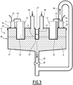
- the photonic spectrometry device 2 comprises a pot 40 for circulating the product 4 to be inspected, having a symmetry of revolution about the axis of symmetry A. As a result, each sensor 12 receives statistically substantially the same quantity of photons coming from the product 4 present in the pot 40.
- the sensors 12 are arranged on the pot 40 so that the product receiving space 4 in the pot 40 is between the sensors 12 and around the sensors 12. This ensures good irradiation of the sensors 12 by the photons emitted by the sensor. product 4.
- the pot 40 comprises a tank 42 of circular section extending along the axis of symmetry A and a lid 44 of circular contour closing, hermetically if necessary, the tank 42.
- the lid 44 is of generally circular shape.
- the lid 44 comprises at least one filling device 48 disposed near the center of the lid 44 coinciding with the axis A and ensuring the rapid filling of the pot 40 and at least one discharge device 46 positioned at the periphery of the lid 44 and ensuring the overflow of the pot 40.
- the filling devices 48 are spaced apart and uniformly distributed in a circle centered on the axis A. According to the configuration of the installation 30, the filling device 48 can also be arranged on a lateral face or on the lower face of the tank 42.
- the tank 42 comprises at least one emptying device 56 feeding at the lowest point of the tank 42 and emptying the pot 40 controlled by the evacuation valve 58. As shown in FIG. figure 3 , the tank 42 comprises a draining device 56 feeding at the center of the bottom of the tank 42.
- the lid 44 comprises a plurality of sensor cells 50 projecting towards the inside of the pot 40 and open towards the outside of the pot 40.
- Each sensor cell 50 defines in the cover 44 a receiving housing of a sensor 12.
- the sensor cells 50 are arranged along the circle of sensors C1.
- the sensor cells 50 are angularly evenly distributed around the axis A.
- the cover 44 comprises a plurality of holding devices 52 of detection module 14 open towards the outside of the pot 40.
- Each holding device 52 defines projecting on the outside of the cover 44 a housing for receiving a detection module 14.
- the holding devices 52 are arranged in a circle of imaginary detection modules C2 centered on the axis A.
- the holding devices 52 are angularly distributed regularly around the axis A.
- the cover 44 comprises a calibration source cell 54 centered on the axis A.
- the standard source cell 54 is disposed between the filling devices 48.
- the standard sources S1, S2 are disposed in the reference source cell 54.
- Each reference source S1, S2 is located in the center of the sensor circle C1 along which sensors 12 are arranged.
- the pot 40 is disposed near an installation 30.
- the detection assembly formed by the measuring pot 40, the sensors 12 and their associated detection modules 14 is supplied with product 4 to be controlled, by a direct route or by a derived channel (parallel channel) of the installation 30.
- the pot 40 is for example disposed at the outlet of a furnace for producing uranium and hydrofluoric acid, on a liquid hydrofluoric acid outlet, in a confined room.
- the detection modules 14 arranged near the sensors 12 make it possible to use short wire links 22 between the detection modules 14 and the sensors 12, in order to maximize the signal-to-noise ratio in detection.
- the analysis modules 16 associated with the detection modules 14 and the sensors 12 may be placed outside the confined room.
- Optical fiber optic link 24 ensures high and reliable data transmission over long distances, for example several tens of meters.
- the spectrometers 6 In operation, during a determined time interval, the spectrometers 6 simultaneously measure the photons emitted by the product 4 present in the measuring pot 40. Each spectrometer 6 provides a spectrum of measurements. After individually resetting each measurement spectrum to determine a net spectrum, the processing module 8 adds the net spectra to determine an overall spectrum resulting from the summation of the net spectra. From the overall spectrum, the processing module 8 determines one or more measurements, for example a concentration of uranium 235 in the product 4.
- the photonic spectrometry device 2 makes it possible to replace a measurement made by a laboratory apparatus on a sample of the product 4 over a period of time T, by n simultaneous measurements (n> 1) on the product 4 at the output of the installation 30, performed by several spectrometers 6 while ensuring a result of the same statistical accuracy acquired over a shorter period, which can be, for example, reduced to T / n.
- the photonic spectrometry device 2 makes it possible to perform satisfactory measurements over a measurement interval of a few minutes, for example from 1 to 5 minutes, while conventional sampling and analysis techniques using laboratory equipment require several tens of minutes or even hours and, depending on the product to be taken, a human intervention in a potentially hazardous environment such as a confined area.
- the photonic spectrometry device 2 thus makes it possible to measure very quickly, over a measurement interval compatible with the monitoring of an industrial process or the control of an industrial process.
- spectrometry is a statistical measure. All photons emitted by the product 4 during the measurement interval are not necessarily detected. Each sensor 12 detects only a portion of the photons that reach the sensor 12.
- the photonic spectrometry device 2 comprises several identical spectrometers 6.
- the sensors 12 although identical, have a dispersion and, under the same conditions, provide different measurements.
- the value of the signals provided by a sensor 12 also depends on its high voltage supply. Even a small change in the relative value of the voltage of this high voltage supply substantially changes the value of the signals supplied. Adjusting this voltage individually for each sensor 12 could theoretically allow the sensors 12 to be calibrated, but this individual adjustment imposes a source of high voltage electrical energy 18 specific sensor 12 and is not industrial because of the significant maintenance involved. To meet the constraints of an industrial process, it is preferable to keep a single high voltage value, which possibly allows the use of a single source of high voltage electrical energy 18 for all sensors 12. All since the sensors 12 are powered by the same high voltage value, the signals delivered will then be different because of the differences in gain and detection efficiency of each sensor 12.
- the senor 12 of each spectrometer 6 is coupled to the associated detection module 14 of this spectrometer 6.
- the sensor 12 and the associated detection module 14 are jointly calibrated.
- the detection module 14 of each spectrometer 6 is initially set so that the signals supplied by the different sensor couples 12 / detection module 14 are identical and linear or substantially identical and linear under the same measurement conditions .
- each sensor pair 12 / detection module 14 is adjusted by adjusting the gain of the photomultiplier 34 coupled to the crystal 32 of the sensor 12 and then by adjusting the detection module 14, for example by adjusting the proportional regulator 38 of the detection module 14.
- the adjustment is performed at each sensor pair 12 / detection module 14, and not at each sensor 12. This allows to take into account the dispersion between the sensors 12 and between the modules detection 14 and ensure that each spectrometer 6 provides substantially the same net spectrum in the presence of the same source of radiation.
- each spectrometer 6 is carried out for example in the presence of at least one standard source S1, S2.
- the proportional controller 38 of the detection module 14 is set so that the output signals supplied by the detection module 14 correspond to the expected values in the presence of the reference source S1, S2.
- each sensor 12 and the detection module 14 associated therewith form an inseparable pair.
- Two detection modules 14 can not be interchanged without swapping the two associated sensors 12 and a sensor 12 can not be replaced without associating its own detection module 14.
- the sensors 12 are powered by the same high-voltage value and are advantageously supplied by the same source of high-voltage electrical energy 18. This simplifies the supply of the sensors 12 and the maintenance operations. For other reasons such as the principle of redundancy implemented in installations nuclear power, as illustrated on the figure 1 it is possible to provide a source of high voltage electrical energy 18 common to, for example, two sensors 12. On the figure 1 the spectrometers 6 are grouped in pairs, the two sensors 12 of the spectrometers 6 of each group being fed by the same source of high voltage electrical energy 18.
- Each sensor 12 may have a drift over time and the sensors 12 may have different drifts.
- the photonic spectrometry device 2 comprises at least one standard source S1, S2 common to the various spectrometers 6 for the drift correction of the sensors 12.
- the sensors 12 are arranged symmetrically around each reference source. S1, S2.
- the drift correction of the sensors 12 is performed from the same standard source S1, S2 which is an additional guarantee for compliance with the principle of ergodicity.
- each sensor 12 The drift of each sensor 12 is corrected by resetting each measurement spectrum according to the measured characteristic spectral line corresponding to the or each reference source S1, S2 and the reference line of the or each reference source S1, S2 so that determining a net spectrum of the radiation emitted by the product 4 and the or each source source S1, S2.
- the photonic spectrometry device 2 comprises at least one standard source S1 having a reference energy higher than that of an element to be detected.
- the isotope 235 of uranium has, among other things, a characteristic gamma-gamma emission at the value of 185.7 keV.
- a photonic spectrometry device 2 suitable for the detection of the uranium isotope 235 comprises, for example, a standard cesium-137 source having a reference characteristic gamma-gamma emission at the value of 662 keV, the influence of which on the accounts for the energy 185.7 keV, that is to say the results of the counting on the measurement interval provided by the analysis module 16, is easily rendered negligible.
- each spectrometric path has a response linearity characteristic
- An error - in relative value - of X% on the measurement of the reference value of the standard source causes a correction - in relative value - of X% of all the measured values.
- the photonic spectrometry device 2 comprises two standard sources S1 and S2 having characteristic spectral lines whose reference energies are different.
- the reference energies of the standard sources S1 and S2 are chosen so as to have a transmission energy which is situated for one of them at one of the two ends of the spectral analysis band in energy. a spectrometer 6 and for the other of them at the other end of the energy spectral analysis band of the same spectrometer 6.
- the correction is optimal for all photons detectable on this energy analysis band.
- the isotope 235 of uranium has, among other things, a characteristic gamma-gamma emission at the value of 185.7 keV.
- a photonic spectrometry device 2 suitable for the detection of uranium 235 comprises, for example, an americium 241 reference source having a reference energy of 59.5 keV and therefore a reference line on the energy spectrum around the 60 keV abscissa. and a cesium 137 standard source having a reference energy of 662 keV and thus a reference line on the energy spectrum around the 662 keV abscissa.
- the figure 5 illustrates an example of a spectrum obtainable in the presence of an americium standard source 241, a standard source of cesium 137 and a sample containing uranium 235.
- the abscissa represents the energy in keV of received photons and the ordinate the number of photons detected.
- the drift correction is performed by correcting each measurement spectrum according to the measured characteristic spectral line and the reference line of each calibration source S1, S2, which ensures a more accurate correction.
- the affine resetting functions are determined so that the measured characteristic lines of the standard sources S1, S2 used coincide, in energy and in counting, with the respective reference lines of the standard sources S1, S2 and then applied to each point of the measurement spectrum. .
- photon sensors comprise a standard source - for example americium 241 - placed in the sensor sealed or sealed to the crystal during their manufacture.
- standard sources have a limited regulatory life. The source and therefore the sensor must be destroyed at the end of the regulation life, whatever the state of the sensor, which limits the life of the sensor. Similarly, if a sensor is defective, the complete sensor is replaced and the standard source is destroyed with the sensor.
- At least one registration function for the registration of the spectra of measurements of a spectrometer 6 is determined for each spectrum of measurements provided by the spectrometer 6.
- at least one registration function for the registration of measurement spectra of a spectrometer 6 is determined from at least one spectrometer of reference measurements of the spectrometer 6 so as to make coincide, for each reference source (S1, S2), a spectral line characteristic of the spectrum of measurements of reference with the reference spectral line of this standard source S1, S2.
- the or each registration function is used to reset several spectra of successive measurements of the spectrometer 6.
- the or each registration function is periodically determined according to a periodicity which depends on the stability of the spectrometer 6. The periodicity may be of the order of the day , of the week or more.
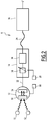
- FIGS. 6 to 8 schematically illustrate industrial installations 30 using a photonic spectrometry device 2 according to the invention for controlling the content of radioisotopes of coproduct and reject effluents.
- the figure 6 illustrates an installation for converting uranium hexafluoride to uranium oxide comprising a furnace 60 receiving, inter alia, as input uranium hexafluoride UF 6 and water H 2 O circulating in countercurrent in oven 60, and outputting uranium oxide U x O y as product and HF hydrofluoric acid as a co-product.
- the pot 40 of the photonic spectrometry device 2 is placed in series on a hydrofluoric acid outlet after condensation in liquid HF so as to verify that the hydrofluoric acid content of uranium 235 is below the regulatory thresholds.
- the figure 7 illustrates a radioactive material recycling facility comprising a reactor 62 receiving as input waste containing radioactive material WMF and reagents R suitable for precipitating the radioactive material, and providing at the outlet of the recycled radioactive material RMF and effluents E.
- the pot 40 of the photonic spectrometry device 2 is disposed in parallel (in parallel) on an effluent outlet E so as to verify that the content of effluents E in radioisotopes, for example some radioisotopes thorium, uranium 235, lead 212, ..., or other radioactive impurities resulting for example from the use of uranium from the treatment of irradiated fuels, called reprocessing uranium, plutonium. is below the regulatory thresholds.
- the recycling plant comprises a recirculation line 64 extending between the outlet of the measuring pot 40 of the photonic spectrometry device 2 and the WMF waste inlet, so that the effluents E are recycled as long as they have content of one or more radioisotopes too high.
- the figure 8 illustrates a set of processing radioactive materials 66 comprising several facilities 68 for processing radioactive materials producing effluents E, collected in an evacuation circuit for their rejection.
- the photonic spectrometry device 2 is disposed in the rejection circuit so as to verify that the effluents E collected have a content of radioisotopes that comply with the regulatory release thresholds.
- the photonic spectrometry device 2 is installed in a main pipe 70 to make measurements on all the effluents E or on a bypass pipe to make the measurements on a fraction of the effluents E collected.
- the photonic spectrometry device 2 can be used to determine the origin of effluent pollution by radioactive material. Indeed, depending on the industrial process at the origin of for example a pollution with uranium, chemical elements characteristic of the process implemented can be associated with uranium. For example, a presence of lead 212 in combination with uranium 235 is a sign of pollution from a facility using reprocessed uranium.
- the processing module 8 of the photonic spectrometry device 2 is configured to determine from the global spectrum the presence of radioisotopes in addition, for example, uranium 235.
- the choice of the implementation of the photonic spectrometry device 2 in series or bypass on an output of the product 4 to be controlled depends on the installation 30 and the flow rate of the product in the output line.
- the processing module 8 comprises a memory in which are stored reference spectra characteristic of certain types of pollution, and is configured to, for example, issue an alarm or trigger a shutdown of the installation 30 in case of correspondence of a net spectrum with a pre-recorded reference spectrum.
- the photon spectrometry device can be produced from commercially available elements and can be placed in situ near or in an installation to control the products supplied by this installation and / or control the installation.
- the invention applies in particular to the measurement of the uranium 235 content at the output of uranium-based nuclear fuel fabrication process or uranium recycling process. In general, the invention applies to the measurement of the content of any radioactive element.
- the invention applies to the measurement of any gamma or X radiation.
- the spectrometers of the invention are gamma and / or X photon spectrometers according to the scintillator used.
Landscapes
- Physics & Mathematics (AREA)
- Spectroscopy & Molecular Physics (AREA)
- Health & Medical Sciences (AREA)
- Life Sciences & Earth Sciences (AREA)
- General Physics & Mathematics (AREA)
- High Energy & Nuclear Physics (AREA)
- Molecular Biology (AREA)
- Measurement Of Radiation (AREA)
- Investigating Or Analysing Materials By Optical Means (AREA)
- Spectrometry And Color Measurement (AREA)
- Investigating, Analyzing Materials By Fluorescence Or Luminescence (AREA)
Claims (15)
- Photonenspektrometrie-Vorrichtung (2), dadurch gekennzeichnet, dass sie aufweist mindestens eine Standardquelle (S1, S2), mehrere identische photonische Spektrometer (6), wobei jedes Spektrometer (6) einen Sensor (12) für Strahlung aufweist und imstande ist, ein Messspektrum bereitzustellen, welches zu den Messungen des Sensors (12) während eines Zeitintervalls korrespondiert, wobei die Spektrometer (6) imstande sind, gleichzeitig Messungen durchzuführen an einem gleichen Erzeugnis (4), welches Strahlung emittiert, und an der oder jeder Standardquelle (S1, S2), und Messspektren für ein gleiches Zeitintervall bereitzustellen, und Verarbeitungsmittel (8, 16), die imstande sind, ein Nettospektrum ausgehend von jedem der Messspektren, die mittels der Spektrometer (6) für ein gleiches Zeitintervall bereitgestellt werden, zu ermitteln mittels Korrigierens des Messspektrums, welches mittels jedes Spektrometers (6) bereitgestellt wird, abhängig von einer Spektrallinie des Messspektrums, welches zu der mindestens einen Standardquelle (S1, S2) korrespondiert, und von einer Referenzlinie der oder jeder Standardquelle (S1, S2), und ein Gesamtspektrum zu ermitteln, welches aus dem Summieren der Nettospektren resultiert, die für ein gleiches Zeitintervall ermittelt werden.
- Photonenspektrometrie-Vorrichtung gemäß Anspruch 1, wobei jedes Spektrometer (6) ein Detektionsmodul (14) aufweist, welches imstande ist, ein elektrisches Signal, welches mittels des Sensors (12) bei der Detektion eines Photons emittiert wird und proportional zur Energie des detektierten Photons ist, in ein digitales Signal zu konvertieren, welches repräsentativ für die Energie des detektierten Photons ist.
- Photonenspektrometrie-Vorrichtung gemäß Anspruch 2, wobei jedes Detektionsmodul (14) steuerbar ist, um das digitale Signal einzustellen, welches mittels des Detektionsmoduls (14) abhängig von dem Signal, das mittels des assoziierten Sensors (12) emittiert wird, bereitgestellt wird.
- Photonenspektrometrie-Vorrichtung gemäß Anspruch 3, wobei jedes Spektrometer (6) anfänglich gesteuert wird mittels Korrigierens des Detektionsmoduls (14) in einer Weise, dass die Paare Sensor (12) / Detektionsmodul (14) der Spektrometer (6) in Anwesenheit einer gleichen Strahlungsquelle im Wesentlichen das gleiche digitale Signal emittieren.
- Photonenspektrometrie-Vorrichtung gemäß irgendeinem der vorherigen Ansprüche, welche mindestens eine Standardquelle (S1, S2) aufweist, die Strahlung emittiert, die den Spektrometern (6) gemeinsam ist, wobei jeder Sensor (12) der Spektrometer (6) statistisch im Wesentlichen eine gleiche Anzahl an Photonen aus der oder jeder Standardquelle (S1, S2) für ein gleiches Zeitintervall empfängt.
- Photonenspektrometrie-Vorrichtung gemäß Anspruch 5, welche mindestens zwei unterschiedliche Standardquellen (S1, S2) aufweist, die den Spektrometern (6) gemeinsam sind.
- Photonenspektrometrie-Vorrichtung gemäß Anspruch 6, welche zwei Standardquellen (S1, S2) aufweist, welche jeweilige Referenz-Spektrallinien haben, die sich beiderseits einer charakteristischen Spektrallinie eines zu detektierenden Elements befinden, insbesondere beiderseits einer charakteristischen Spektrallinie von Uran 235.
- Photonenspektrometrie-Vorrichtung gemäß irgendeinem der vorherigen Ansprüche, wobei die Verarbeitungsmittel (8, 16) imstande sind, jedes Nettospektrum zu ermitteln mittels Korrigierens von jedem Messspektrum abhängig von einer charakteristischen Spektrallinie des Messspektrums, welches zu der oder jeder Standardquelle (S1, S2) korrespondiert, und von einer Referenzlinie der oder jeder Standardquelle (S1, S2).
- Photonenspektrometrie-Vorrichtung gemäß irgendeinem der Ansprüche 1 bis 7, wobei die Verarbeitungsmittel (8, 16) imstande sind, mindestens eine Korrekturfunktion zu ermitteln für das Korrigieren der Messspektren eines Spektrometers (6) ausgehend von einem Referenz-Messspektrum des Spektrometers (6), wobei die oder jede Korrekturfunktion ermittelt wird, sodass für jede Standardquelle (S1, S2) eine charakteristische Spektrallinie des Referenz-Messspektrums mit der Referenz-Spektrallinie dieser Standardquelle (S1, S2) übereinstimmt.
- Photonenspektrometrie-Vorrichtung gemäß irgendeinem der vorherigen Ansprüche zum Messen von Gammastrahlung oder zum Messen von Röntgenstrahlung.
- Verfahren zur Photonenspektrometrie, welches die folgenden Schritte aufweist:- Bereitstellen von Messspektren mit Hilfe von identischen Spektrometern (6), wobei jedes Messspektrum resultiert aus Messungen, die an einem gleichen Erzeugnis (4), welches Strahlung emittiert, und an mindestens einer Standardquelle (S1, S2) durchgeführt werden während eines gleichen Zeitintervalls mittels eines jeweiligen Spektrometers (6),- Ermitteln eines Nettospektrums ausgehend von jedem Messspektrum mittels Korrigierens des Messspektrums abhängig von mindestens einer Spektrallinie des Messspektrums, welches mittels des Spektrometers (6) bereitgestellt wird, wobei die oder jede Spektrallinie zu einer Standardquelle (S1, S2) korrespondiert, und von der Referenz-Linie der oder jeder Standardquelle (S1, S2),- Ermitteln eines Gesamtspektrums, welches aus dem Summieren der Nettospektren resultiert.
- Verfahren gemäß Anspruch 11, wobei jedes Nettospektrum ermittelt wird ausgehend von jedem Messspektrum, welches mittels eines Spektrometers (6) bereitgestellt wird, mittels Korrigierens des Messspektrums abhängig von einer Spektrallinie des Messspektrums, welches mittels des Spektrometers (6) bereitgestellt wird, wobei die Spektrallinie zu mindestens einer Standardquelle (S1, S2) korrespondiert, und von der Referenz-Linie der oder jeder Standardquelle (S1, S2).
- Verfahren gemäß Anspruch 11, wobei mindestens eine Korrekturfunktion für das Korrigieren der Messspektren eines Spektrometers (6) ermittelt wird ausgehend von einem Referenz-Messspektrum, welches mittels des Spektrometers (6) bereitgestellt wird, wobei die oder jede Korrekturfunktion ermittelt wird, sodass für die oder jede Standardquelle (S1, S2) eine charakteristische Spektrallinie des Referenz-Messspektrums mit der Referenz-Spektrallinie dieser Standardquelle (S1, S2) übereinstimmt.
- Verfahren zum Kalibrieren einer Photonenspektrometrie-Vorrichtung gemäß Anspruch 3 oder 4, aufweisend den Schritt des Steuern eines Detektionsmoduls (14), welches imstande ist, ein elektrisches Signal am Ausgang des Sensors (12) von jedem Spektrometer (6) in ein digitales Signal umzuwandeln, welches repräsentativ ist für die Energie von jedem detektierten Photon, auf eine Weise, dass die Spektrometer (6) Spektren bereitstellen, die in Anwesenheit einer gleichen Strahlungsquelle im Wesentlichen identisch sind.
- Verwendung einer Photonenspektrometrie-Vorrichtung gemäß einem der Ansprüche 1 bis 10 zum Messen des Uran-235-Gehalts an Fluorwasserstoffsäure, die sich bei der Herstellung von Uranoxid ergibt, zum Messen des Gehalts von mindestens einem Radioisotop der Abwässer einer Wiederverwertungsanlage für radioaktive Stoffe oder zum Messen des Gehalts von mindestens einem Radioisotop der Abwässer einer Anlage zur Verarbeitung radioaktiver Stoffe vor der Ableitung.
Applications Claiming Priority (2)
| Application Number | Priority Date | Filing Date | Title |
|---|---|---|---|
| FR1152069A FR2972811B1 (fr) | 2011-03-14 | 2011-03-14 | Dispositif et procede de spectrometrie photonique, procede de calibrage du dispositif et utilisation du dispositif |
| PCT/EP2012/054256 WO2012123404A1 (fr) | 2011-03-14 | 2012-03-12 | Dispositif et procede de spectrometrie photonique, procede de calibrage du dispositif et utilisation du dispositif |
Publications (2)
| Publication Number | Publication Date |
|---|---|
| EP2686705A1 EP2686705A1 (de) | 2014-01-22 |
| EP2686705B1 true EP2686705B1 (de) | 2019-07-17 |
Family
ID=45841475
Family Applications (1)
| Application Number | Title | Priority Date | Filing Date |
|---|---|---|---|
| EP12709067.8A Active EP2686705B1 (de) | 2011-03-14 | 2012-03-12 | Photonenspektrometrische vorrichtung und verfahren, verfahren zur kalibrierung der vorrichtung und verwendung der vorrichtung |
Country Status (7)
| Country | Link |
|---|---|
| US (1) | US9400336B2 (de) |
| EP (1) | EP2686705B1 (de) |
| JP (1) | JP6351977B2 (de) |
| KR (1) | KR101894959B1 (de) |
| CN (1) | CN103534611B (de) |
| FR (1) | FR2972811B1 (de) |
| WO (1) | WO2012123404A1 (de) |
Families Citing this family (7)
| Publication number | Priority date | Publication date | Assignee | Title |
|---|---|---|---|---|
| JP2015094624A (ja) * | 2013-11-11 | 2015-05-18 | 国立大学法人京都大学 | 放射線検出システム、データ処理装置、放射線検出方法および波高値分布データ処理プログラム |
| US11231508B2 (en) | 2014-06-06 | 2022-01-25 | Siemens Medical Solutions Usa, Inc. | Gamma camera dead time determination in real time using long lived radioisotopes |
| US10398394B2 (en) * | 2017-01-06 | 2019-09-03 | General Electric Company | Energy-discriminating photon-counting detector and the use thereof |
| US9958324B1 (en) * | 2017-02-15 | 2018-05-01 | MarqMetrix Inc. | Enclosed benchtop raman spectrometry device |
| US10408675B2 (en) | 2017-02-15 | 2019-09-10 | Marqmetrix, Inc. | Enclosed benchtop Raman spectrometry device |
| JP6664367B2 (ja) * | 2017-11-27 | 2020-03-13 | シャープ株式会社 | 検出器、ならびに、検出器の補正方法、校正方法、検出装置 |
| WO2021229555A2 (en) * | 2020-05-14 | 2021-11-18 | NewSight Imaging Ltd. | A method and a system for analyzing a spectral signature of a compound specimen |
Citations (3)
| Publication number | Priority date | Publication date | Assignee | Title |
|---|---|---|---|---|
| US3009062A (en) * | 1956-12-05 | 1961-11-14 | Jr William A Brooksbank | Absorption analyzer |
| EP0256902A2 (de) * | 1986-07-10 | 1988-02-24 | Electricite De France | Teilchenmessgerät für Ionisationsstrahlung |
| US20090134337A1 (en) * | 2007-11-27 | 2009-05-28 | William Robert Russ | Hybrid radiation detection system |
Family Cites Families (15)
| Publication number | Priority date | Publication date | Assignee | Title |
|---|---|---|---|---|
| US3124679A (en) * | 1964-03-10 | Nuclear determination of | ||
| AT326787B (de) | 1968-03-13 | 1975-12-29 | Lab Prof De Rudolf Berthold | Einrichtung zur automatischen driftstabilisierung bei der intensitätsmessung von kernstrahlungen |
| JPS5215383A (en) * | 1975-07-25 | 1977-02-04 | Dainippon Toryo Co Ltd | Raidation dose meter element supporter |
| CA1128215A (en) * | 1979-06-15 | 1982-07-20 | Hudson's Bay Oil And Gas Company Limited | Gamma ray prospecting system |
| JPS56168579A (en) * | 1980-05-30 | 1981-12-24 | Japan Atom Energy Res Inst | Combined gamma standard ray source for calibrating gamma-ray spectrometer |
| JPS59200998A (ja) * | 1983-04-28 | 1984-11-14 | 三菱重工業株式会社 | ウランを含む廃液の処理方法 |
| JPH06308058A (ja) * | 1993-04-20 | 1994-11-04 | Nippon Steel Corp | ラザフォード後方散乱分光分析装置 |
| JPH07140252A (ja) * | 1993-11-17 | 1995-06-02 | Toshiba Corp | 臨界警報装置 |
| FR2771725B1 (fr) | 1997-11-28 | 2000-02-04 | Franco Belge Combustibles | Procede et dispositif de conversion directe d'hexafluorure d'uranium en oxyde d'uranium |
| JP4127840B2 (ja) * | 2005-11-30 | 2008-07-30 | 独立行政法人放射線医学総合研究所 | 放射線測定装置及びデータ処理方法 |
| JP4763582B2 (ja) * | 2006-11-28 | 2011-08-31 | 日立アロカメディカル株式会社 | 排水モニタシステム及び排水測定方法 |
| CA2610543A1 (en) | 2006-11-29 | 2008-05-29 | Global Nuclear Fuel-Americas, Llc | System and method for stabilizing the measurement of radioactivity |
| CN101470207A (zh) | 2007-12-29 | 2009-07-01 | 同方威视技术股份有限公司 | 多道脉冲分析器及峰飘实时修正方法 |
| GB0809198D0 (en) | 2008-05-21 | 2008-06-25 | Farnsworth Ag | A novel auto calibration technique for radiation detectors |
| US20100264319A1 (en) * | 2009-04-17 | 2010-10-21 | Massimo Morichi | Intelligent Sensor Platform |
-
2011
- 2011-03-14 FR FR1152069A patent/FR2972811B1/fr not_active Expired - Fee Related
-
2012
- 2012-03-12 KR KR1020137027090A patent/KR101894959B1/ko not_active Expired - Fee Related
- 2012-03-12 CN CN201280023309.1A patent/CN103534611B/zh not_active Expired - Fee Related
- 2012-03-12 JP JP2013558389A patent/JP6351977B2/ja not_active Expired - Fee Related
- 2012-03-12 EP EP12709067.8A patent/EP2686705B1/de active Active
- 2012-03-12 US US14/005,000 patent/US9400336B2/en not_active Expired - Fee Related
- 2012-03-12 WO PCT/EP2012/054256 patent/WO2012123404A1/fr not_active Ceased
Patent Citations (3)
| Publication number | Priority date | Publication date | Assignee | Title |
|---|---|---|---|---|
| US3009062A (en) * | 1956-12-05 | 1961-11-14 | Jr William A Brooksbank | Absorption analyzer |
| EP0256902A2 (de) * | 1986-07-10 | 1988-02-24 | Electricite De France | Teilchenmessgerät für Ionisationsstrahlung |
| US20090134337A1 (en) * | 2007-11-27 | 2009-05-28 | William Robert Russ | Hybrid radiation detection system |
Also Published As
| Publication number | Publication date |
|---|---|
| US20140003579A1 (en) | 2014-01-02 |
| KR20140024868A (ko) | 2014-03-03 |
| CN103534611A (zh) | 2014-01-22 |
| EP2686705A1 (de) | 2014-01-22 |
| US9400336B2 (en) | 2016-07-26 |
| CN103534611B (zh) | 2017-04-05 |
| FR2972811A1 (fr) | 2012-09-21 |
| JP6351977B2 (ja) | 2018-07-04 |
| KR101894959B1 (ko) | 2018-09-04 |
| JP2014512523A (ja) | 2014-05-22 |
| FR2972811B1 (fr) | 2014-02-07 |
| WO2012123404A1 (fr) | 2012-09-20 |
Similar Documents
| Publication | Publication Date | Title |
|---|---|---|
| EP2686706B1 (de) | Photonenspektrometer, entsprechendes verfahren und verwendung der vorrichtung | |
| EP2686705A1 (de) | Photonenspektrometrische vorrichtung und verfahren, verfahren zur kalibrierung der vorrichtung und verwendung der vorrichtung | |
| JP7026443B2 (ja) | 放射性ダストモニタ | |
| US10060795B2 (en) | Multichannel spectrophotometer and data processing method for multichannel spectrophotometer | |
| EP2338157A1 (de) | Einrichtung zur inline-messung schneller epithermischer neutronen | |
| KR20210053591A (ko) | 대규모 방사성 폐기물의 방사능 측정 및 분류 시스템 | |
| EP3617751B1 (de) | Selbstkalibrierungsverfahren einer vorrichtung zur erfassung von ionisierender strahlung | |
| EP3492950B1 (de) | Verfahren zur kalibrierung eines gammaspektrometers, entsprechendes kalibrierungssystem und entsprechende gammaspektrometrieeinheit | |
| EP3842840B1 (de) | Verfahren zur bestimmung einer verzerrung, die die pixel eines pixelierten detektors für ionisierende strahlung beeinflusst | |
| EP4457545B1 (de) | Verfahren zur verarbeitung eines röntgen- oder gamma-strahlenspektrums und entsprechende vorrichtung | |
| EP2483711B1 (de) | Verfahren zur bestimmung des isotopenverhältnisses von spaltstoffen in einer spaltkammer | |
| WO2019082952A1 (ja) | シンチレータユニット、放射線測定装置及び放射線測定方法 | |
| KR102321893B1 (ko) | 대규모 방사성 폐기물의 전수검사를 위한 방사능 측정 시스템 | |
| FR3118494A1 (fr) | Dispositif de détection comportant différentes couches de scintillation | |
| EP3172592B1 (de) | Vorrichtung und verfahren zur messung der radioaktivität eines materials | |
| FR3053516B1 (fr) | Procede d'identification d'un assemblage de combustible nucleaire, systeme d'identification et installation nucleaire comportant un tel systeme d'identification | |
| FR2564975A1 (fr) | Procede et appareil pour mesurer la concentration du plutonium dans des courants de liquide de retraitement de combustible nucleaire irradie | |
| CN104931997A (zh) | X射线能量的平场图像测量装置及方法 | |
| OA18483A (en) | Device and method for measuring the radioactivity of a material. | |
| EP1416296A2 (de) | Elektronische Einrichtung zum Messen der Strahlendosis |
Legal Events
| Date | Code | Title | Description |
|---|---|---|---|
| PUAI | Public reference made under article 153(3) epc to a published international application that has entered the european phase |
Free format text: ORIGINAL CODE: 0009012 |
|
| 17P | Request for examination filed |
Effective date: 20130906 |
|
| AK | Designated contracting states |
Kind code of ref document: A1 Designated state(s): AL AT BE BG CH CY CZ DE DK EE ES FI FR GB GR HR HU IE IS IT LI LT LU LV MC MK MT NL NO PL PT RO RS SE SI SK SM TR |
|
| DAX | Request for extension of the european patent (deleted) | ||
| STAA | Information on the status of an ep patent application or granted ep patent |
Free format text: STATUS: EXAMINATION IS IN PROGRESS |
|
| 17Q | First examination report despatched |
Effective date: 20180206 |
|
| RAP1 | Party data changed (applicant data changed or rights of an application transferred) |
Owner name: FRAMATOME |
|
| GRAP | Despatch of communication of intention to grant a patent |
Free format text: ORIGINAL CODE: EPIDOSNIGR1 |
|
| STAA | Information on the status of an ep patent application or granted ep patent |
Free format text: STATUS: GRANT OF PATENT IS INTENDED |
|
| INTG | Intention to grant announced |
Effective date: 20190212 |
|
| GRAS | Grant fee paid |
Free format text: ORIGINAL CODE: EPIDOSNIGR3 |
|
| GRAA | (expected) grant |
Free format text: ORIGINAL CODE: 0009210 |
|
| STAA | Information on the status of an ep patent application or granted ep patent |
Free format text: STATUS: THE PATENT HAS BEEN GRANTED |
|
| AK | Designated contracting states |
Kind code of ref document: B1 Designated state(s): AL AT BE BG CH CY CZ DE DK EE ES FI FR GB GR HR HU IE IS IT LI LT LU LV MC MK MT NL NO PL PT RO RS SE SI SK SM TR |
|
| REG | Reference to a national code |
Ref country code: GB Ref legal event code: FG4D Free format text: NOT ENGLISH |
|
| REG | Reference to a national code |
Ref country code: CH Ref legal event code: EP |
|
| REG | Reference to a national code |
Ref country code: IE Ref legal event code: FG4D Free format text: LANGUAGE OF EP DOCUMENT: FRENCH |
|
| REG | Reference to a national code |
Ref country code: DE Ref legal event code: R096 Ref document number: 602012062060 Country of ref document: DE |
|
| REG | Reference to a national code |
Ref country code: AT Ref legal event code: REF Ref document number: 1156362 Country of ref document: AT Kind code of ref document: T Effective date: 20190815 |
|
| REG | Reference to a national code |
Ref country code: NL Ref legal event code: MP Effective date: 20190717 |
|
| REG | Reference to a national code |
Ref country code: LT Ref legal event code: MG4D |
|
| REG | Reference to a national code |
Ref country code: AT Ref legal event code: MK05 Ref document number: 1156362 Country of ref document: AT Kind code of ref document: T Effective date: 20190717 |
|
| PG25 | Lapsed in a contracting state [announced via postgrant information from national office to epo] |
Ref country code: SE Free format text: LAPSE BECAUSE OF FAILURE TO SUBMIT A TRANSLATION OF THE DESCRIPTION OR TO PAY THE FEE WITHIN THE PRESCRIBED TIME-LIMIT Effective date: 20190717 Ref country code: LT Free format text: LAPSE BECAUSE OF FAILURE TO SUBMIT A TRANSLATION OF THE DESCRIPTION OR TO PAY THE FEE WITHIN THE PRESCRIBED TIME-LIMIT Effective date: 20190717 Ref country code: HR Free format text: LAPSE BECAUSE OF FAILURE TO SUBMIT A TRANSLATION OF THE DESCRIPTION OR TO PAY THE FEE WITHIN THE PRESCRIBED TIME-LIMIT Effective date: 20190717 Ref country code: PT Free format text: LAPSE BECAUSE OF FAILURE TO SUBMIT A TRANSLATION OF THE DESCRIPTION OR TO PAY THE FEE WITHIN THE PRESCRIBED TIME-LIMIT Effective date: 20191118 Ref country code: NL Free format text: LAPSE BECAUSE OF FAILURE TO SUBMIT A TRANSLATION OF THE DESCRIPTION OR TO PAY THE FEE WITHIN THE PRESCRIBED TIME-LIMIT Effective date: 20190717 Ref country code: FI Free format text: LAPSE BECAUSE OF FAILURE TO SUBMIT A TRANSLATION OF THE DESCRIPTION OR TO PAY THE FEE WITHIN THE PRESCRIBED TIME-LIMIT Effective date: 20190717 Ref country code: NO Free format text: LAPSE BECAUSE OF FAILURE TO SUBMIT A TRANSLATION OF THE DESCRIPTION OR TO PAY THE FEE WITHIN THE PRESCRIBED TIME-LIMIT Effective date: 20191017 Ref country code: BG Free format text: LAPSE BECAUSE OF FAILURE TO SUBMIT A TRANSLATION OF THE DESCRIPTION OR TO PAY THE FEE WITHIN THE PRESCRIBED TIME-LIMIT Effective date: 20191017 Ref country code: AT Free format text: LAPSE BECAUSE OF FAILURE TO SUBMIT A TRANSLATION OF THE DESCRIPTION OR TO PAY THE FEE WITHIN THE PRESCRIBED TIME-LIMIT Effective date: 20190717 |
|
| PG25 | Lapsed in a contracting state [announced via postgrant information from national office to epo] |
Ref country code: AL Free format text: LAPSE BECAUSE OF FAILURE TO SUBMIT A TRANSLATION OF THE DESCRIPTION OR TO PAY THE FEE WITHIN THE PRESCRIBED TIME-LIMIT Effective date: 20190717 Ref country code: ES Free format text: LAPSE BECAUSE OF FAILURE TO SUBMIT A TRANSLATION OF THE DESCRIPTION OR TO PAY THE FEE WITHIN THE PRESCRIBED TIME-LIMIT Effective date: 20190717 Ref country code: IS Free format text: LAPSE BECAUSE OF FAILURE TO SUBMIT A TRANSLATION OF THE DESCRIPTION OR TO PAY THE FEE WITHIN THE PRESCRIBED TIME-LIMIT Effective date: 20191117 Ref country code: RS Free format text: LAPSE BECAUSE OF FAILURE TO SUBMIT A TRANSLATION OF THE DESCRIPTION OR TO PAY THE FEE WITHIN THE PRESCRIBED TIME-LIMIT Effective date: 20190717 Ref country code: LV Free format text: LAPSE BECAUSE OF FAILURE TO SUBMIT A TRANSLATION OF THE DESCRIPTION OR TO PAY THE FEE WITHIN THE PRESCRIBED TIME-LIMIT Effective date: 20190717 Ref country code: GR Free format text: LAPSE BECAUSE OF FAILURE TO SUBMIT A TRANSLATION OF THE DESCRIPTION OR TO PAY THE FEE WITHIN THE PRESCRIBED TIME-LIMIT Effective date: 20191018 |
|
| PG25 | Lapsed in a contracting state [announced via postgrant information from national office to epo] |
Ref country code: TR Free format text: LAPSE BECAUSE OF FAILURE TO SUBMIT A TRANSLATION OF THE DESCRIPTION OR TO PAY THE FEE WITHIN THE PRESCRIBED TIME-LIMIT Effective date: 20190717 |
|
| PG25 | Lapsed in a contracting state [announced via postgrant information from national office to epo] |
Ref country code: RO Free format text: LAPSE BECAUSE OF FAILURE TO SUBMIT A TRANSLATION OF THE DESCRIPTION OR TO PAY THE FEE WITHIN THE PRESCRIBED TIME-LIMIT Effective date: 20190717 Ref country code: IT Free format text: LAPSE BECAUSE OF FAILURE TO SUBMIT A TRANSLATION OF THE DESCRIPTION OR TO PAY THE FEE WITHIN THE PRESCRIBED TIME-LIMIT Effective date: 20190717 Ref country code: DK Free format text: LAPSE BECAUSE OF FAILURE TO SUBMIT A TRANSLATION OF THE DESCRIPTION OR TO PAY THE FEE WITHIN THE PRESCRIBED TIME-LIMIT Effective date: 20190717 Ref country code: PL Free format text: LAPSE BECAUSE OF FAILURE TO SUBMIT A TRANSLATION OF THE DESCRIPTION OR TO PAY THE FEE WITHIN THE PRESCRIBED TIME-LIMIT Effective date: 20190717 Ref country code: EE Free format text: LAPSE BECAUSE OF FAILURE TO SUBMIT A TRANSLATION OF THE DESCRIPTION OR TO PAY THE FEE WITHIN THE PRESCRIBED TIME-LIMIT Effective date: 20190717 |
|
| PG25 | Lapsed in a contracting state [announced via postgrant information from national office to epo] |
Ref country code: CZ Free format text: LAPSE BECAUSE OF FAILURE TO SUBMIT A TRANSLATION OF THE DESCRIPTION OR TO PAY THE FEE WITHIN THE PRESCRIBED TIME-LIMIT Effective date: 20190717 Ref country code: IS Free format text: LAPSE BECAUSE OF FAILURE TO SUBMIT A TRANSLATION OF THE DESCRIPTION OR TO PAY THE FEE WITHIN THE PRESCRIBED TIME-LIMIT Effective date: 20200224 Ref country code: SM Free format text: LAPSE BECAUSE OF FAILURE TO SUBMIT A TRANSLATION OF THE DESCRIPTION OR TO PAY THE FEE WITHIN THE PRESCRIBED TIME-LIMIT Effective date: 20190717 Ref country code: SK Free format text: LAPSE BECAUSE OF FAILURE TO SUBMIT A TRANSLATION OF THE DESCRIPTION OR TO PAY THE FEE WITHIN THE PRESCRIBED TIME-LIMIT Effective date: 20190717 |
|
| REG | Reference to a national code |
Ref country code: DE Ref legal event code: R097 Ref document number: 602012062060 Country of ref document: DE |
|
| PLBE | No opposition filed within time limit |
Free format text: ORIGINAL CODE: 0009261 |
|
| STAA | Information on the status of an ep patent application or granted ep patent |
Free format text: STATUS: NO OPPOSITION FILED WITHIN TIME LIMIT |
|
| PG2D | Information on lapse in contracting state deleted |
Ref country code: IS |
|
| 26N | No opposition filed |
Effective date: 20200603 |
|
| PG25 | Lapsed in a contracting state [announced via postgrant information from national office to epo] |
Ref country code: SI Free format text: LAPSE BECAUSE OF FAILURE TO SUBMIT A TRANSLATION OF THE DESCRIPTION OR TO PAY THE FEE WITHIN THE PRESCRIBED TIME-LIMIT Effective date: 20190717 |
|
| REG | Reference to a national code |
Ref country code: DE Ref legal event code: R119 Ref document number: 602012062060 Country of ref document: DE |
|
| PG25 | Lapsed in a contracting state [announced via postgrant information from national office to epo] |
Ref country code: MC Free format text: LAPSE BECAUSE OF FAILURE TO SUBMIT A TRANSLATION OF THE DESCRIPTION OR TO PAY THE FEE WITHIN THE PRESCRIBED TIME-LIMIT Effective date: 20190717 |
|
| REG | Reference to a national code |
Ref country code: CH Ref legal event code: PL |
|
| REG | Reference to a national code |
Ref country code: BE Ref legal event code: MM Effective date: 20200331 |
|
| PG25 | Lapsed in a contracting state [announced via postgrant information from national office to epo] |
Ref country code: LU Free format text: LAPSE BECAUSE OF NON-PAYMENT OF DUE FEES Effective date: 20200312 |
|
| PG25 | Lapsed in a contracting state [announced via postgrant information from national office to epo] |
Ref country code: LI Free format text: LAPSE BECAUSE OF NON-PAYMENT OF DUE FEES Effective date: 20200331 Ref country code: DE Free format text: LAPSE BECAUSE OF NON-PAYMENT OF DUE FEES Effective date: 20201001 Ref country code: IE Free format text: LAPSE BECAUSE OF NON-PAYMENT OF DUE FEES Effective date: 20200312 Ref country code: CH Free format text: LAPSE BECAUSE OF NON-PAYMENT OF DUE FEES Effective date: 20200331 |
|
| PG25 | Lapsed in a contracting state [announced via postgrant information from national office to epo] |
Ref country code: BE Free format text: LAPSE BECAUSE OF NON-PAYMENT OF DUE FEES Effective date: 20200331 |
|
| PG25 | Lapsed in a contracting state [announced via postgrant information from national office to epo] |
Ref country code: MT Free format text: LAPSE BECAUSE OF FAILURE TO SUBMIT A TRANSLATION OF THE DESCRIPTION OR TO PAY THE FEE WITHIN THE PRESCRIBED TIME-LIMIT Effective date: 20190717 Ref country code: CY Free format text: LAPSE BECAUSE OF FAILURE TO SUBMIT A TRANSLATION OF THE DESCRIPTION OR TO PAY THE FEE WITHIN THE PRESCRIBED TIME-LIMIT Effective date: 20190717 |
|
| PG25 | Lapsed in a contracting state [announced via postgrant information from national office to epo] |
Ref country code: MK Free format text: LAPSE BECAUSE OF FAILURE TO SUBMIT A TRANSLATION OF THE DESCRIPTION OR TO PAY THE FEE WITHIN THE PRESCRIBED TIME-LIMIT Effective date: 20190717 |
|
| PGFP | Annual fee paid to national office [announced via postgrant information from national office to epo] |
Ref country code: GB Payment date: 20240325 Year of fee payment: 13 |
|
| PGFP | Annual fee paid to national office [announced via postgrant information from national office to epo] |
Ref country code: FR Payment date: 20240325 Year of fee payment: 13 |
|
| GBPC | Gb: european patent ceased through non-payment of renewal fee |
Effective date: 20250312 |
|
| PG25 | Lapsed in a contracting state [announced via postgrant information from national office to epo] |
Ref country code: GB Free format text: LAPSE BECAUSE OF NON-PAYMENT OF DUE FEES Effective date: 20250312 |
|
| PG25 | Lapsed in a contracting state [announced via postgrant information from national office to epo] |
Ref country code: FR Free format text: LAPSE BECAUSE OF NON-PAYMENT OF DUE FEES Effective date: 20250331 |