EP3617751B1 - Selbstkalibrierungsverfahren einer vorrichtung zur erfassung von ionisierender strahlung - Google Patents
Selbstkalibrierungsverfahren einer vorrichtung zur erfassung von ionisierender strahlung Download PDFInfo
- Publication number
- EP3617751B1 EP3617751B1 EP19192857.1A EP19192857A EP3617751B1 EP 3617751 B1 EP3617751 B1 EP 3617751B1 EP 19192857 A EP19192857 A EP 19192857A EP 3617751 B1 EP3617751 B1 EP 3617751B1
- Authority
- EP
- European Patent Office
- Prior art keywords
- energy
- spectrometer
- ref
- ionizing radiation
- measured
- Prior art date
- Legal status (The legal status is an assumption and is not a legal conclusion. Google has not performed a legal analysis and makes no representation as to the accuracy of the status listed.)
- Active
Links
Images



Classifications
-
- H—ELECTRICITY
- H01—ELECTRIC ELEMENTS
- H01J—ELECTRIC DISCHARGE TUBES OR DISCHARGE LAMPS
- H01J49/00—Particle spectrometers or separator tubes
- H01J49/44—Energy spectrometers, e.g. alpha-, beta-spectrometers
-
- G—PHYSICS
- G01—MEASURING; TESTING
- G01T—MEASUREMENT OF NUCLEAR OR X-RADIATION
- G01T1/00—Measuring X-radiation, gamma radiation, corpuscular radiation, or cosmic radiation
- G01T1/36—Measuring spectral distribution of X-rays or of nuclear radiation spectrometry
-
- G—PHYSICS
- G01—MEASURING; TESTING
- G01T—MEASUREMENT OF NUCLEAR OR X-RADIATION
- G01T1/00—Measuring X-radiation, gamma radiation, corpuscular radiation, or cosmic radiation
- G01T1/36—Measuring spectral distribution of X-rays or of nuclear radiation spectrometry
- G01T1/40—Stabilisation of spectrometers
-
- G—PHYSICS
- G01—MEASURING; TESTING
- G01T—MEASUREMENT OF NUCLEAR OR X-RADIATION
- G01T7/00—Details of radiation-measuring instruments
- G01T7/005—Details of radiation-measuring instruments calibration techniques
-
- G—PHYSICS
- G01—MEASURING; TESTING
- G01T—MEASUREMENT OF NUCLEAR OR X-RADIATION
- G01T1/00—Measuring X-radiation, gamma radiation, corpuscular radiation, or cosmic radiation
- G01T1/16—Measuring radiation intensity
- G01T1/20—Measuring radiation intensity with scintillation detectors
- G01T1/2002—Optical details, e.g. reflecting or diffusing layers
Definitions
- the present invention relates to a spectrometry method for the detection and characterization of ionizing radiation.
- It also relates to a method for calibrating a spectrometer and to a method for increasing the spectral sensitivity of a spectrometer implementing such a spectrometry method.
- ionizing radiation detectors In many fields, it is known to use ionizing radiation detectors to detect radiation emitted by a radioactive source, in a given environment.
- the information provided by these detectors can be useful in areas surrounding nuclear power plants, in industrial sites, places in the fight against the illicit transport of radioactive materials or more simply, in search of isolated sources of radiation. .
- Some ionizing radiation detectors are now able to measure a level of radioactivity and identify the source of this radiation from the measurement of the distribution of radiation energies (spectrometry).
- ionizing radiation spectrometers using the scintillation principle are subject to detection drifts and to aging of their various constituent elements: photo detector, amplifier, scintillator, etc.
- ionizing radiation can induce structural defects in the body of the scintillator, which are then at the origin of alterations, or artefacts, of varying importance in the measurements taken.
- certain components of these spectrometers can still be sensitive to ambient humidity and / or to temperature.
- the spectral sensitivity, also called energy resolution, of a scintillator is limited to a few percent, generally from three (3) to twelve (12) percent depending on the scintillator.
- the document US2011101232 discloses a spectrometry method, comprising the following step: for at least one energy of ionizing radiation, obtaining, for each energy, a curve of the number of photons detected, during a measurement interval, as a function of time, by means of a spectrometer.
- the documents FR3020470 and US7065473 each disclose a similar process. In addition, these three documents seek to propose a solution to the problem of energy calibration.
- the document US2018113160 describes a method for determining a characteristic of a pulse signal, and, in particular, the arrival time of said pulse.
- the present invention aims to overcome the drawbacks of the prior art by proposing a spectrometry method and a device for detecting ionizing radiation, simple in their design and in their operating mode, reliable and economical, making it possible to improve the capacities of a spectrometer.
- Another objective of the present invention is a method for calibrating a spectrometer making it possible to correct any measurement drifts observed while allowing real-time self-calibration of the spectrometer without adding one or more standard sources.
- Yet another object of the present invention is a method of increasing the spectral sensitivity of a spectrometer to ensure better differentiation of radioisotopes.
- Yet another object of the present invention is a detector of ionizing radiation economical and compact for the implementation of these processes.
- the present method is applicable for the measurement of any alpha (a), beta ( ⁇ ), gamma (y), X-rays or neutrons (n) radiation or even any other type of ionizing particles, the spectral analysis band of the spectrometer depending on the scintillator used, the detection geometry and the electronics used.
- the term “event” is understood to mean an interaction between incident ionizing radiation and the scintillator.
- Each event generates the emission of scintillation photons by the scintillator. This photon emission follows a scintillation decline curve over time.
- step a we thus obtain for each energy E i of incident ionizing radiation, or excitation energy, a curve or graphical representation in two dimensions (amplitude as a function of time), called temporal distribution, or also called decline of scintillation.
- the number a i can be obtained by a simple ratio of two determined time periods (T 1 / T 2 ) or result from a more complex calculation such as (T 1 + T 3 ) / T 2 or (T 1 x exp (T 3 )) / T 2 .
- this scintillation decay curve can be described as a mono-exponential, multi-exponential, or non-exponential function.
- step b) of the spectrometry method can consist of an adjustment of each curve, or part of a curve, of scintillation decline obtained for a radiation energy E i by an adjustment function, which will be chosen from a mono-exponential adjustment function, a function multi-exponential adjustment function or a non-exponential adjustment function such as polynomial.
- step c) when the number a i is equal to the constant a i (REF) or when the one or all of the parameters PAJ i are equal to the reference parameter or parameters PAJ i (REF), the energy E i of the ionizing radiation for which the corresponding curve was obtained in step a) with the scintillation spectrometer is equal to E i (REF) of associated reference.
- step b the time periods are taken to be identical for all of the curves.
- they may change depending on the type of particles to be detected and they necessarily change depending on the type of scintillator used.
- Such a method advantageously allows real-time, or even continuous, calibration of the spectrometer. It is thus no longer necessary to carry out maintenance, which allows financial savings as well as time.
- At least one of said time periods corresponds only to a decay time, that is to say to weakening of the number of photons detected for the interaction of the ionizing radiation with this scintillator.
- the present invention also relates to a method according to claim 6 for calibrating a spectrometer.
- this calibration method aims to continuously correct the drifts of the spectrometer by comparing the amplitude of the scintillation events and the temporal response whose terms have been calculated by one of the two methods described in step b) of the method. spectrometry.
- the reference is the temporal distribution, or decline of scintillation, because the latter is advantageously not subject to variations such as those which are observed for an amplitude measurement.
- Such a calibration method ensures a high degree of accuracy in the calibration of the spectrometer.
- Such a calibration method favors a statistical approach, that is to say a number of significant events.
- the present invention also relates to a method according to claim 7 for increasing the spectral sensitivity of a spectrometer.
- the spectral sensitivity is defined by the amplitude distribution of the events forming a photoelectric peak on the gamma spectrum. This peak corresponds to the scintillation events for which all of the energy of the incident ionizing radiation has been deposited. This energy deposition can take place during a single interaction between this ionizing radiation and the scintillator, called photoelectric interaction, or during several interactions (interaction by the Compton effect followed by a photoelectric interaction of the scattered photon). These are in particular the events composed of several Compton-type interactions, which reduce the spectral sensitivity of the spectrometer.
- the spectrum thus obtained is used to identify said ionizing radiation corresponding to each reference energy E i (REF) and optionally, to display the nature of said corresponding ionizing radiation.
- Such a method of increasing the spectral sensitivity of a spectrometer ensures a high gain in resolution of this spectrometer.
- the present invention also relates to a computer program product which in particular is stored on a computer readable medium, according to claim 10.
- this computer can be a microprocessor such as an on-board microprocessor, that is to say integrated into a portable device.
- a microprocessor such as an on-board microprocessor, that is to say integrated into a portable device.
- it may also be a programmable logic circuit (FPGA - “Field Programmable Gate Array”).
- This computer can also be a fixed or mobile workstation.
- the present invention also relates to a device for detecting ionizing radiation comprising a processing assembly comprising a microprocessor and a computer storage unit, this storage unit containing a data library comprising data on several ionizing radiations, said detection device comprising a spectrometer comprising a scintillator coupled to a photodetector.
- this detection device comprises a set of software instructions thanks to which said device can control said spectrometer, detect and identify one or more ionizing radiations interacting with said scintillator, said software instructions belonging to said computer program as described. previously.
- this device comprises a portable housing, this housing being provided with an opening for detecting ionizing radiation, said scintillator having a pointing axis and being arranged in this housing so that its pointing axis is oriented towards said opening.
- this detection device does not have a standard source, there is no protective screen provided in the box and the detection device has a wide detection field.
- said photodetector comprises a measurement module configured to convert an electrical signal emitted by said photodetector following the detection of a photon and proportional to the number of visible photons detected by the photodetector, into a digital signal representative of the energy of the photon measured.
- such a detector 10 is particularly advantageous for monitoring an environment and possibly a contaminated object in order to counter an immediate danger in the event of measurement of high concentrations.
- This detector 10 comprises a detector body provided with an inlet window 11 on its upper face, this window 11 being intended for the passage of particles to be detected.
- this entry window 11 may comprise a light-tight film, such as a film known under the trade name MYLAR® or any other thin layer opaque at light wavelengths detectable by the photodetector.
- a light indicator 12 making it possible to display the operating state of the detector (low battery, operating or stopped).
- It also comprises a connector 13 such as a USB port for connecting this detector to a computer in order to load or unload data and / or computer programs, as well as an on / off button 14.
- a connector 13 such as a USB port for connecting this detector to a computer in order to load or unload data and / or computer programs, as well as an on / off button 14.
- such a detector 10 could also include a communication unit for receiving and transmitting data.
- this communication unit could be a wireless communication module configured to communicate according to one of the following protocols: Sigfox, LoRa or even ZigBee. In other words, it is a low power wireless communication module that saves battery power on the detector. It could also include a wireless communication module such as a Bluetooth communication module for sending data or messages when a Sigfox or LoraWan non-coverage detection would be carried out.
- Wi-Fi Wi-Fi
- IEEE 802.15.1 Bluetooth
- 2G 3G, 4G, 5G or even GSM or GPRS.
- a wireless localization means such as a GPS receiver, to determine its position as well as a storage unit for keeping time-stamped data.
- Each of these data would then include a position and a time at which this position was acquired by the GPS receiver as well as the detection or not of ionizing radiation.
- the body of the detector is here made entirely from a noble wood such as ash, but it could also be made from another material such as a hard plastic.
- the interior walls of this detector body are opaque to block exterior light.
- a spectrometer 15 In the interior volume delimited by the detector body 10 is placed a spectrometer 15 making it possible to detect particles, count them and obtain energy spectra.
- This spectrometer thus comprises a scintillator 16 for simultaneously measuring ⁇ and ⁇ radiation.
- This scintillator 16 is here formed by a stack of layers of different inorganic and organic scintillator materials.
- This scintillator 16 is an elongated body, such as a bar, placed opposite the slit to receive particles passing through this inlet window 11.
- the dimensions of this scintillator are purely by way of illustration of 6 * 6 * 50mm. They could also be 6 * 6 * 100mm or even 30 * 30 * 30mm.
- a photodetector 17 is optically coupled to this scintillator 16 and comprises a measurement module 18 configured to convert an electrical signal emitted by this photodetector 17 following the detection of a photon and proportional to the number of visible photons detected by the photodetector, into a digital signal representative of the energy of the photon measured.
- This photodetector 17 therefore has a sensitivity that matches the emission wavelengths of the scintillator.
- This is a sensor of the “silicon photomultiplier” (or SiPM) type, but it can also be traditional photomultiplier tubes or photodiodes.
- It also comprises a processing assembly 19 comprising a microprocessor, or a programmable logic circuit (FPGA), and a computer storage unit, this storage unit containing a data library comprising data on ionizing radiation (energy, etc. ).
- a processing assembly 19 comprising a microprocessor, or a programmable logic circuit (FPGA), and a computer storage unit, this storage unit containing a data library comprising data on ionizing radiation (energy, etc. ).
- the Figure 3 shows an example of a so-called scintillation decline curve obtained in step a) for an energy of ionizing radiation incident on the scintillator.
- the microprocessor or the FPGA, determines two distinct time periods T 1 and T 2 . For each of these time periods, it then integrates the number of photons emitted by the scintillator, also called the quantity of light, then calculates the ratio of the total number of photons detected over the period T 1 over the total number of photons detected over the period T 2 which provides a number a associated with the excitation energy (step b).
- step c it compares the number a thus obtained with reference constants a (REF), b (REF), c (REF), ... each associated with a reference energy E (REF) to identify the reference energy E (REF) for which the number a was obtained.
- This method thus makes it possible to identify very precisely the excitation energy, real, for which the scintillation decline curve was obtained in step a).
- the Figure 4 represents scintillation decay curves measured by means of a scintillation spectrometer with a CsI: Tl scintillator material (Thallium-doped Cesium Iodide) for two different ionizing radiation energies, namely x-rays of 17 keV excitation and gamma of 662 KeV.
- CsI Tl scintillator material
- the upper scintillation decay curve 20 was obtained for a gamma radiation energy of 662 keV and the lower scintillation decay curve 21 was obtained for an x-ray energy of 17 keV.
- This change in the dynamics of light emission is linked to the variation in the density of electronic charges produced during the interaction of each gamma particle with matter.
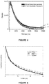
- the Figure 5 thus illustrates part of the scintillation decline curve obtained for a scintillation spectrometer with an inorganic scintillator of alkali halide type for different energies of ionizing radiation: two beams (17 keV and 59 keV) originating from atoms of Americium 241 ( 241 Am) and a beam from Cobalt 57 ( 57 Co). The amplitude of the measured signals was normalized.
- the curve shown in Figure 6 not being subject to any calibration, it constitutes a graph of reference used to calibrate a measurement obtained by the scintillation spectrometer.
- step b) The matching of the adjustment parameters obtained in step b) for an energy E i measured by the scintillation spectrometer with reference adjustment parameters (A 1 [REF], A 2 [REF], t 1 [REF], t 2 [REF]) obtained for a reference energy E i REF), therefore makes it possible to determine the real radiation energy for which the scintillation decline curve was measured.
- the determination of the reference adjustment parameter (s), as well as of the associated reference energy can be carried out at any time with at least two known sources of ionizing radiation.
- step c) the comparison of the number a i with a constant a i (REF) makes it possible to determine the real energy, or even the reference energy, E i (REF) of the ionizing radiation for which the curve was measured by the scintillation spectrometer.
- these time windows are typically defined by one tenth (1/10 th ) of the total integration time.
Landscapes
- Physics & Mathematics (AREA)
- Spectroscopy & Molecular Physics (AREA)
- Health & Medical Sciences (AREA)
- Life Sciences & Earth Sciences (AREA)
- General Physics & Mathematics (AREA)
- High Energy & Nuclear Physics (AREA)
- Molecular Biology (AREA)
- Chemical & Material Sciences (AREA)
- Analytical Chemistry (AREA)
- Measurement Of Radiation (AREA)
- Analysing Materials By The Use Of Radiation (AREA)
Claims (10)
- Spektrometrie-Verfahren, umfassend den folgenden Schritt:a) für mindestens eine Energie Ei ionisierender Strahlung, Erhalten einer Kurve der Anzahl von während eines Messintervalls detektierten Photonen als Funktion der Zeit mittels eines Spektrometers (15), für jede Energie Ei,wobei das Verfahren dadurch gekennzeichnet ist, dass es weiter die folgenden Schritte umfasst:b) für jede so erhaltene Kurve, Berechnen eines Verhältnisses der Gesamtzahl der über mindestens zwei bestimmte und unterschiedliche Zeiträume detektierten Photonen, um für jede Energie Ei ionisierender Strahlung eine Zahl ai zu erhalten, oder
für jede so erhaltene Kurve, Erhalten eines oder mehrerer Anpassungsparameter PAJi durch Durchführen einer Anpassung der entsprechenden Kurve durch eine Anpassungsfunktion,c) Vergleichen jeder Zahl ai oder jedes Anpassungsparameters oder Satzes von Anpassungsparametern PAJi, die so erhalten wurden, mit Referenz-Konstanten ai(REF) bzw. mit Referenz-Anpassungsparametern PAJi(REF), die Referenz-Energien Ei(REF) zugeordnet sind, um für jede Zahl ai oder jeden Anpassungsparameter oder Satz von Anpassungsparametern PAJi die Referenz-Energie Ei(REF) der ionisierenden Strahlung zu bestimmen, für welche die entsprechende Kurve gemessen wurde. - Verfahren nach Anspruch 1, dadurch gekennzeichnet, dass in Schritt a) eine Kurve für mindestens zwei unterschiedliche Energien Ei ionisierender Strahlung erhalten wird.
- Verfahren nach Anspruch 1 oder 2, dadurch gekennzeichnet, dass in Schritt b) die Anpassung durch eine multi-exponentielle Anpassungsfunktion erhalten wird.
- Verfahren nach einem der vorhergehenden Ansprüche, dadurch gekennzeichnet, dass das Spektrometer (15) einen mit einem Fotodetektor (17) gekoppelten Szintillator (16) umfasst, wobei in Schritt b) die Zeiträume so gewählt werden, dass die Differenz zwischen den Zahlen ai für zwei verschiedene Energien Ei maximiert wird.
- Verfahren nach einem der vorhergehenden Ansprüche, dadurch gekennzeichnet, dass in dem Spektrometer (15) ein Szintillator (16) verwendet wird, der einen Nichtproportionalitätsfaktor seiner Szintillationseffizienz in Abhängigkeit von der Energie Ei der ionisierenden Strahlung von größer oder gleich 2 % Abweichung pro Größenordnung der einfallenden Strahlung aufweist.
- Verfahren zum Kalibrieren eines Spektrometers (15), dadurch gekennzeichnet, dass ein Spektrometrie-Verfahren nach einem der Ansprüche 1 bis 5 verwendet wird, und dass die folgenden zusätzlichen Schritte ausgeführt werden:d) Vergleichen der in Schritt c) bestimmten Referenz-Energien Ei(REF) der ionisierenden Strahlung mit den entsprechenden Energien Ei(mes), die von dem Spektrometer (15) in einem Energiespektrum der ionisierenden Strahlung gemessen werden, um einen Fehlerwert zu erhalten, der jeder Messung der Energie der ionisierenden Strahlung Ei(mes) zugeordnet ist, wobei der Fehlerwert ein Maß einer Differenz zwischen der von dem Spektrometer (15) gemessenen Energie Ei(mes) und der entsprechenden, in Schritt c) bestimmten Referenz-Energie Ei(REF) ist, unde) dann, wenn mehrere Fehlerwerte ungleich Null sind und im Absolutwert größer als Schwellenwerte sind, Bestimmen einer Energiekorrektur, die permanent an jeder von diesem Spektrometer (15) gemessenen Energie Ei(mes) vorzunehmen ist.
- Verfahren zur Erhöhung der spektralen Empfindlichkeit eines Spektrometers (15), dadurch gekennzeichnet, dass ein Spektrometrie-Verfahren nach einem der Ansprüche 1 bis 5 verwendet wird, und dass für jedes von dem Spektrometer (15) gemessene Ereignis die folgenden zusätzlichen Schritte durchgeführt werden:d) Bestimmen der Differenz zwischen der von dem Spektrometer (15) gemessenen Energie Ei(mes) und der entsprechenden in Schritt c) bestimmten Referenz-Energie Ei(REF), um einen Energiedifferenzwert für das Ereignis zu erhalten,e) Vergleichen des Absolutwerts dieser Energiedifferenz mit einem vorbestimmten Schwellenwert, der Akzeptabilität genannt wird, undf) falls der Absolutwert kleiner oder gleich dem Schwellenwert ist, dann Berücksichtigen dieses Ereignisses bei der Bildung eines Spektrums der Anzahl der vom Spektrometer (15) gemessenen Ereignisse als Funktion der Energie Ei(REF) der ionisierenden Strahlung, und falls der Absolutwert größer ist als der Schwellenwert, dann Ausschließen des betrachteten Ereignisses,danach Erhalten eines Spektrums der Gesamtzahl der gemessenen Ereignisse für jede Referenz-Energie Ei(REF).
- Detektionsvorrichtung für ionisierende Strahlung, umfassend eine Verarbeitungseinheit mit einem Mikroprozessor und einer Daten-Speichereinheit, wobei die Speichereinheit eine Datenbibliothek enthält, die Daten über mehrere ionisierende Strahlungen umfasst, wobei die Detektionsvorrichtung ein Spektrometer (15) umfasst, das mindestens einen Szintillator (16) umfasst, der mit einem Fotodetektor (17) gekoppelt ist, dadurch gekennzeichnet, dass die Detektionsvorrichtung dazu konfiguriert ist, die Schritte des Spektrometrie-Verfahrens nach einem der Ansprüche 1 bis 5 oder des Verfahrens zum Kalibrieren nach Anspruch 6 oder des Verfahrens zur Erhöhung der spektralen Empfindlichkeit nach Anspruch 7 durchzuführen.
- Vorrichtung nach Anspruch 8, dadurch gekennzeichnet, dass der Fotodetektor (17) ein Messmodul umfasst, das konfiguriert ist, um ein elektrisches Signal, das von dem Fotodetektor (17) nach der Detektion eines Photons emittiert wird und proportional zur Anzahl der sichtbaren Photonen ist, die vom Fotodetektor (17) detektiert werden, in ein digitales Signal umzuwandeln, das die Energie des gemessenen Photons darstellt.
- Computerprogrammprodukt, das insbesondere auf einem computerlesbaren Medium gespeichert oder in Form eines Signals implementiert ist, wobei das Computerprogrammprodukt Anweisungen umfasst, die dann, wenn sie durch eine Vorrichtung nach Anspruch 9 oder 10 durchgeführt werden, bewirken, dass die Vorrichtung die Schritte des Spektrometrie-Verfahrens nach einem der Ansprüche 1 bis 5 oder des Verfahrens zum Kalibrieren nach Anspruch 6 oder des Verfahrens zur Erhöhung der spektralen Empfindlichkeit nach Anspruch 7 durchführt.
Applications Claiming Priority (1)
| Application Number | Priority Date | Filing Date | Title |
|---|---|---|---|
| FR1857708A FR3085492B1 (fr) | 2018-08-28 | 2018-08-28 | Procede de spectrometrie et dispositif de detection de rayonnements ionisants pour sa mise en œuvre |
Publications (2)
| Publication Number | Publication Date |
|---|---|
| EP3617751A1 EP3617751A1 (de) | 2020-03-04 |
| EP3617751B1 true EP3617751B1 (de) | 2021-09-08 |
Family
ID=65494243
Family Applications (1)
| Application Number | Title | Priority Date | Filing Date |
|---|---|---|---|
| EP19192857.1A Active EP3617751B1 (de) | 2018-08-28 | 2019-08-21 | Selbstkalibrierungsverfahren einer vorrichtung zur erfassung von ionisierender strahlung |
Country Status (3)
| Country | Link |
|---|---|
| US (1) | US11056333B2 (de) |
| EP (1) | EP3617751B1 (de) |
| FR (1) | FR3085492B1 (de) |
Families Citing this family (2)
| Publication number | Priority date | Publication date | Assignee | Title |
|---|---|---|---|---|
| CN111896990B (zh) * | 2020-07-10 | 2023-01-24 | 成都理工大学 | 一种基于Frechet距离的放射源活度监测方法 |
| SE545450C2 (en) * | 2021-03-24 | 2023-09-12 | Scienta Omicron Ab | Charged particle spectrometer and method for calibration |
Citations (1)
| Publication number | Priority date | Publication date | Assignee | Title |
|---|---|---|---|---|
| US20180113160A1 (en) * | 2016-10-24 | 2018-04-26 | Xia Llc | Ratio-Reference Measurement of the Arrival Time and/or Amplitude of a Digitized Electronic Pulse |
Family Cites Families (3)
| Publication number | Priority date | Publication date | Assignee | Title |
|---|---|---|---|---|
| US7065473B2 (en) * | 1999-08-27 | 2006-06-20 | William K. Warburton | Method and apparatus for improving resolution in spectrometers processing output steps from non-ideal signal sources |
| WO2007009495A1 (en) * | 2005-07-22 | 2007-01-25 | Icx Radiation Gmbh | Detector for the measurement of ionizing radiation |
| FR3020470B1 (fr) * | 2014-04-23 | 2016-05-20 | Commissariat Energie Atomique | Dispositif et procede simulant la detection de sources radioactives mobiles |
-
2018
- 2018-08-28 FR FR1857708A patent/FR3085492B1/fr active Active
-
2019
- 2019-08-21 EP EP19192857.1A patent/EP3617751B1/de active Active
- 2019-08-27 US US16/552,113 patent/US11056333B2/en active Active
Patent Citations (1)
| Publication number | Priority date | Publication date | Assignee | Title |
|---|---|---|---|---|
| US20180113160A1 (en) * | 2016-10-24 | 2018-04-26 | Xia Llc | Ratio-Reference Measurement of the Arrival Time and/or Amplitude of a Digitized Electronic Pulse |
Also Published As
| Publication number | Publication date |
|---|---|
| FR3085492B1 (fr) | 2021-06-04 |
| EP3617751A1 (de) | 2020-03-04 |
| US20200075309A1 (en) | 2020-03-05 |
| FR3085492A1 (fr) | 2020-03-06 |
| US11056333B2 (en) | 2021-07-06 |
Similar Documents
| Publication | Publication Date | Title |
|---|---|---|
| EP2510338B1 (de) | Verfahren und vorrichtung zur erkennung eines materials mittels der übertragungsfunktion | |
| EP2035861B1 (de) | Einrichtung zum lokalisieren und abbilden von gamma- oder röntgenstrahlungsquellen | |
| EP3374801B1 (de) | Vorrichtung zur bestimmung einer deponierten dosis und zugehöriges verfahren | |
| WO2011067251A1 (fr) | Procédé d'étalonnage d'un détecteur de rayonnement x | |
| JP7026443B2 (ja) | 放射性ダストモニタ | |
| EP2686705B1 (de) | Photonenspektrometrische vorrichtung und verfahren, verfahren zur kalibrierung der vorrichtung und verwendung der vorrichtung | |
| FR2650398A1 (fr) | Procede de mesure d'une grandeur physique a caractere aleatoire et impulsionnel, ou transformable en impulsionnel, et application en spectrometrie gamma | |
| EP2686706B1 (de) | Photonenspektrometer, entsprechendes verfahren und verwendung der vorrichtung | |
| FR3002648A1 (fr) | Procede de mesure de dose au moyen d'un detecteur de rayonnements, notamment d'un detecteur de rayonnements x ou gamma, utilise en mode spectroscopique, et systeme de mesure de dose, utilisant ce procede | |
| EP3617751A1 (de) | Selbstkalibrierungsverfahren einer vorrichtung zur erfassung von ionisierender strahlung | |
| EP1718992B1 (de) | Elektronische spektrometrie-diagnoseschaltung und assoziierte zählende kette | |
| EP2446304A1 (de) | Verfahren zur unterscheidung einer gamma-komponente und einer neutronenkomponente bei einem elektronischen signal | |
| EP3492950B1 (de) | Verfahren zur kalibrierung eines gammaspektrometers, entsprechendes kalibrierungssystem und entsprechende gammaspektrometrieeinheit | |
| EP2329511A1 (de) | System zur überwachung der ertragsveränderung eines bildvervielfältigers und entsprechendes verfahren | |
| EP4457545B1 (de) | Verfahren zur verarbeitung eines röntgen- oder gamma-strahlenspektrums und entsprechende vorrichtung | |
| EP3674753A1 (de) | Verfahren zur kalibrierung eines spektrometer-detektors | |
| WO2023186850A1 (fr) | Appareil pour la surveillance en temps réel du radon et du thoron, notamment dans un environnement ionisant | |
| EP4457546A1 (de) | Verfahren zur energiekalibrierung eines spektrometriedetektors | |
| EP3237932B1 (de) | Verfahren zur kalibrierung eines detektors für ionisierende strahlung und zugehörige vorrichtung | |
| EP4004606B1 (de) | Gerät zur analyse von radioaktiven abfallbehältern und entsprechendes analyseverfahren | |
| WO2017042256A1 (fr) | Dispositif d'analyse in situ d'un dechet radiologique contenant l'isotope chlore 36 | |
| EP4394454A1 (de) | Verfahren zur zerstörungsfreien messung der anreicherung von uran | |
| EP3172592B1 (de) | Vorrichtung und verfahren zur messung der radioaktivität eines materials | |
| WO2024141620A1 (fr) | Procédé de mesure non destructive de l'activité de 238u ou de u | |
| EP3264139A1 (de) | Detektorkopf und dazugehöriges aktivitätsmessgerät |
Legal Events
| Date | Code | Title | Description |
|---|---|---|---|
| PUAI | Public reference made under article 153(3) epc to a published international application that has entered the european phase |
Free format text: ORIGINAL CODE: 0009012 |
|
| STAA | Information on the status of an ep patent application or granted ep patent |
Free format text: STATUS: THE APPLICATION HAS BEEN PUBLISHED |
|
| AK | Designated contracting states |
Kind code of ref document: A1 Designated state(s): AL AT BE BG CH CY CZ DE DK EE ES FI FR GB GR HR HU IE IS IT LI LT LU LV MC MK MT NL NO PL PT RO RS SE SI SK SM TR |
|
| AX | Request for extension of the european patent |
Extension state: BA ME |
|
| STAA | Information on the status of an ep patent application or granted ep patent |
Free format text: STATUS: REQUEST FOR EXAMINATION WAS MADE |
|
| 17P | Request for examination filed |
Effective date: 20200814 |
|
| RBV | Designated contracting states (corrected) |
Designated state(s): AL AT BE BG CH CY CZ DE DK EE ES FI FR GB GR HR HU IE IS IT LI LT LU LV MC MK MT NL NO PL PT RO RS SE SI SK SM TR |
|
| STAA | Information on the status of an ep patent application or granted ep patent |
Free format text: STATUS: EXAMINATION IS IN PROGRESS |
|
| 17Q | First examination report despatched |
Effective date: 20210217 |
|
| GRAP | Despatch of communication of intention to grant a patent |
Free format text: ORIGINAL CODE: EPIDOSNIGR1 |
|
| STAA | Information on the status of an ep patent application or granted ep patent |
Free format text: STATUS: GRANT OF PATENT IS INTENDED |
|
| INTG | Intention to grant announced |
Effective date: 20210407 |
|
| RIN1 | Information on inventor provided before grant (corrected) |
Inventor name: PATTON, GAEL |
|
| GRAS | Grant fee paid |
Free format text: ORIGINAL CODE: EPIDOSNIGR3 |
|
| GRAA | (expected) grant |
Free format text: ORIGINAL CODE: 0009210 |
|
| STAA | Information on the status of an ep patent application or granted ep patent |
Free format text: STATUS: THE PATENT HAS BEEN GRANTED |
|
| AK | Designated contracting states |
Kind code of ref document: B1 Designated state(s): AL AT BE BG CH CY CZ DE DK EE ES FI FR GB GR HR HU IE IS IT LI LT LU LV MC MK MT NL NO PL PT RO RS SE SI SK SM TR |
|
| REG | Reference to a national code |
Ref country code: GB Ref legal event code: FG4D Free format text: NOT ENGLISH |
|
| REG | Reference to a national code |
Ref country code: CH Ref legal event code: EP Ref country code: AT Ref legal event code: REF Ref document number: 1429061 Country of ref document: AT Kind code of ref document: T Effective date: 20210915 |
|
| REG | Reference to a national code |
Ref country code: DE Ref legal event code: R096 Ref document number: 602019007505 Country of ref document: DE |
|
| REG | Reference to a national code |
Ref country code: IE Ref legal event code: FG4D Free format text: LANGUAGE OF EP DOCUMENT: FRENCH |
|
| REG | Reference to a national code |
Ref country code: LT Ref legal event code: MG9D |
|
| REG | Reference to a national code |
Ref country code: NL Ref legal event code: FP |
|
| PG25 | Lapsed in a contracting state [announced via postgrant information from national office to epo] |
Ref country code: SE Free format text: LAPSE BECAUSE OF FAILURE TO SUBMIT A TRANSLATION OF THE DESCRIPTION OR TO PAY THE FEE WITHIN THE PRESCRIBED TIME-LIMIT Effective date: 20210908 Ref country code: RS Free format text: LAPSE BECAUSE OF FAILURE TO SUBMIT A TRANSLATION OF THE DESCRIPTION OR TO PAY THE FEE WITHIN THE PRESCRIBED TIME-LIMIT Effective date: 20210908 Ref country code: FI Free format text: LAPSE BECAUSE OF FAILURE TO SUBMIT A TRANSLATION OF THE DESCRIPTION OR TO PAY THE FEE WITHIN THE PRESCRIBED TIME-LIMIT Effective date: 20210908 Ref country code: ES Free format text: LAPSE BECAUSE OF FAILURE TO SUBMIT A TRANSLATION OF THE DESCRIPTION OR TO PAY THE FEE WITHIN THE PRESCRIBED TIME-LIMIT Effective date: 20210908 Ref country code: LT Free format text: LAPSE BECAUSE OF FAILURE TO SUBMIT A TRANSLATION OF THE DESCRIPTION OR TO PAY THE FEE WITHIN THE PRESCRIBED TIME-LIMIT Effective date: 20210908 Ref country code: BG Free format text: LAPSE BECAUSE OF FAILURE TO SUBMIT A TRANSLATION OF THE DESCRIPTION OR TO PAY THE FEE WITHIN THE PRESCRIBED TIME-LIMIT Effective date: 20211208 Ref country code: HR Free format text: LAPSE BECAUSE OF FAILURE TO SUBMIT A TRANSLATION OF THE DESCRIPTION OR TO PAY THE FEE WITHIN THE PRESCRIBED TIME-LIMIT Effective date: 20210908 Ref country code: NO Free format text: LAPSE BECAUSE OF FAILURE TO SUBMIT A TRANSLATION OF THE DESCRIPTION OR TO PAY THE FEE WITHIN THE PRESCRIBED TIME-LIMIT Effective date: 20211208 |
|
| REG | Reference to a national code |
Ref country code: AT Ref legal event code: MK05 Ref document number: 1429061 Country of ref document: AT Kind code of ref document: T Effective date: 20210908 |
|
| PG25 | Lapsed in a contracting state [announced via postgrant information from national office to epo] |
Ref country code: LV Free format text: LAPSE BECAUSE OF FAILURE TO SUBMIT A TRANSLATION OF THE DESCRIPTION OR TO PAY THE FEE WITHIN THE PRESCRIBED TIME-LIMIT Effective date: 20210908 Ref country code: GR Free format text: LAPSE BECAUSE OF FAILURE TO SUBMIT A TRANSLATION OF THE DESCRIPTION OR TO PAY THE FEE WITHIN THE PRESCRIBED TIME-LIMIT Effective date: 20211209 |
|
| PG25 | Lapsed in a contracting state [announced via postgrant information from national office to epo] |
Ref country code: AT Free format text: LAPSE BECAUSE OF FAILURE TO SUBMIT A TRANSLATION OF THE DESCRIPTION OR TO PAY THE FEE WITHIN THE PRESCRIBED TIME-LIMIT Effective date: 20210908 |
|
| PG25 | Lapsed in a contracting state [announced via postgrant information from national office to epo] |
Ref country code: IS Free format text: LAPSE BECAUSE OF FAILURE TO SUBMIT A TRANSLATION OF THE DESCRIPTION OR TO PAY THE FEE WITHIN THE PRESCRIBED TIME-LIMIT Effective date: 20220108 Ref country code: SM Free format text: LAPSE BECAUSE OF FAILURE TO SUBMIT A TRANSLATION OF THE DESCRIPTION OR TO PAY THE FEE WITHIN THE PRESCRIBED TIME-LIMIT Effective date: 20210908 Ref country code: SK Free format text: LAPSE BECAUSE OF FAILURE TO SUBMIT A TRANSLATION OF THE DESCRIPTION OR TO PAY THE FEE WITHIN THE PRESCRIBED TIME-LIMIT Effective date: 20210908 Ref country code: RO Free format text: LAPSE BECAUSE OF FAILURE TO SUBMIT A TRANSLATION OF THE DESCRIPTION OR TO PAY THE FEE WITHIN THE PRESCRIBED TIME-LIMIT Effective date: 20210908 Ref country code: PT Free format text: LAPSE BECAUSE OF FAILURE TO SUBMIT A TRANSLATION OF THE DESCRIPTION OR TO PAY THE FEE WITHIN THE PRESCRIBED TIME-LIMIT Effective date: 20220110 Ref country code: PL Free format text: LAPSE BECAUSE OF FAILURE TO SUBMIT A TRANSLATION OF THE DESCRIPTION OR TO PAY THE FEE WITHIN THE PRESCRIBED TIME-LIMIT Effective date: 20210908 Ref country code: EE Free format text: LAPSE BECAUSE OF FAILURE TO SUBMIT A TRANSLATION OF THE DESCRIPTION OR TO PAY THE FEE WITHIN THE PRESCRIBED TIME-LIMIT Effective date: 20210908 Ref country code: CZ Free format text: LAPSE BECAUSE OF FAILURE TO SUBMIT A TRANSLATION OF THE DESCRIPTION OR TO PAY THE FEE WITHIN THE PRESCRIBED TIME-LIMIT Effective date: 20210908 Ref country code: AL Free format text: LAPSE BECAUSE OF FAILURE TO SUBMIT A TRANSLATION OF THE DESCRIPTION OR TO PAY THE FEE WITHIN THE PRESCRIBED TIME-LIMIT Effective date: 20210908 |
|
| REG | Reference to a national code |
Ref country code: DE Ref legal event code: R097 Ref document number: 602019007505 Country of ref document: DE |
|
| PLBE | No opposition filed within time limit |
Free format text: ORIGINAL CODE: 0009261 |
|
| STAA | Information on the status of an ep patent application or granted ep patent |
Free format text: STATUS: NO OPPOSITION FILED WITHIN TIME LIMIT |
|
| PG25 | Lapsed in a contracting state [announced via postgrant information from national office to epo] |
Ref country code: DK Free format text: LAPSE BECAUSE OF FAILURE TO SUBMIT A TRANSLATION OF THE DESCRIPTION OR TO PAY THE FEE WITHIN THE PRESCRIBED TIME-LIMIT Effective date: 20210908 |
|
| 26N | No opposition filed |
Effective date: 20220609 |
|
| PG25 | Lapsed in a contracting state [announced via postgrant information from national office to epo] |
Ref country code: SI Free format text: LAPSE BECAUSE OF FAILURE TO SUBMIT A TRANSLATION OF THE DESCRIPTION OR TO PAY THE FEE WITHIN THE PRESCRIBED TIME-LIMIT Effective date: 20210908 |
|
| PG25 | Lapsed in a contracting state [announced via postgrant information from national office to epo] |
Ref country code: IT Free format text: LAPSE BECAUSE OF FAILURE TO SUBMIT A TRANSLATION OF THE DESCRIPTION OR TO PAY THE FEE WITHIN THE PRESCRIBED TIME-LIMIT Effective date: 20210908 |
|
| PG25 | Lapsed in a contracting state [announced via postgrant information from national office to epo] |
Ref country code: MC Free format text: LAPSE BECAUSE OF FAILURE TO SUBMIT A TRANSLATION OF THE DESCRIPTION OR TO PAY THE FEE WITHIN THE PRESCRIBED TIME-LIMIT Effective date: 20210908 |
|
| PG25 | Lapsed in a contracting state [announced via postgrant information from national office to epo] |
Ref country code: LU Free format text: LAPSE BECAUSE OF NON-PAYMENT OF DUE FEES Effective date: 20220821 |
|
| PG25 | Lapsed in a contracting state [announced via postgrant information from national office to epo] |
Ref country code: IE Free format text: LAPSE BECAUSE OF NON-PAYMENT OF DUE FEES Effective date: 20220821 |
|
| PG25 | Lapsed in a contracting state [announced via postgrant information from national office to epo] |
Ref country code: HU Free format text: LAPSE BECAUSE OF FAILURE TO SUBMIT A TRANSLATION OF THE DESCRIPTION OR TO PAY THE FEE WITHIN THE PRESCRIBED TIME-LIMIT; INVALID AB INITIO Effective date: 20190821 |
|
| PG25 | Lapsed in a contracting state [announced via postgrant information from national office to epo] |
Ref country code: CY Free format text: LAPSE BECAUSE OF FAILURE TO SUBMIT A TRANSLATION OF THE DESCRIPTION OR TO PAY THE FEE WITHIN THE PRESCRIBED TIME-LIMIT Effective date: 20210908 |
|
| PG25 | Lapsed in a contracting state [announced via postgrant information from national office to epo] |
Ref country code: MK Free format text: LAPSE BECAUSE OF FAILURE TO SUBMIT A TRANSLATION OF THE DESCRIPTION OR TO PAY THE FEE WITHIN THE PRESCRIBED TIME-LIMIT Effective date: 20210908 |
|
| PG25 | Lapsed in a contracting state [announced via postgrant information from national office to epo] |
Ref country code: TR Free format text: LAPSE BECAUSE OF FAILURE TO SUBMIT A TRANSLATION OF THE DESCRIPTION OR TO PAY THE FEE WITHIN THE PRESCRIBED TIME-LIMIT Effective date: 20210908 |
|
| PG25 | Lapsed in a contracting state [announced via postgrant information from national office to epo] |
Ref country code: MT Free format text: LAPSE BECAUSE OF FAILURE TO SUBMIT A TRANSLATION OF THE DESCRIPTION OR TO PAY THE FEE WITHIN THE PRESCRIBED TIME-LIMIT Effective date: 20210908 |
|
| PGFP | Annual fee paid to national office [announced via postgrant information from national office to epo] |
Ref country code: NL Payment date: 20250829 Year of fee payment: 7 |
|
| PGFP | Annual fee paid to national office [announced via postgrant information from national office to epo] |
Ref country code: DE Payment date: 20250916 Year of fee payment: 7 |
|
| PGFP | Annual fee paid to national office [announced via postgrant information from national office to epo] |
Ref country code: BE Payment date: 20250829 Year of fee payment: 7 Ref country code: GB Payment date: 20250919 Year of fee payment: 7 |
|
| PGFP | Annual fee paid to national office [announced via postgrant information from national office to epo] |
Ref country code: FR Payment date: 20250721 Year of fee payment: 7 |
|
| PGFP | Annual fee paid to national office [announced via postgrant information from national office to epo] |
Ref country code: CH Payment date: 20250930 Year of fee payment: 7 |
|
| REG | Reference to a national code |
Ref country code: CH Ref legal event code: R14 Free format text: ST27 STATUS EVENT CODE: U-0-0-R10-R14 (AS PROVIDED BY THE NATIONAL OFFICE) Effective date: 20260415 Ref country code: CH Ref legal event code: R17 Free format text: ST27 STATUS EVENT CODE: U-0-0-R10-R17 (AS PROVIDED BY THE NATIONAL OFFICE) Effective date: 20260415 |
|
| REG | Reference to a national code |
Ref country code: DE Ref legal event code: R081 Ref document number: 602019007505 Country of ref document: DE Owner name: BERTIN TECHNOLOGIES, FR Free format text: FORMER OWNER: ICOHUP, LIMOGES, FR |