EP2685051A1 - Einströmsegment für eine Strömungsmaschine - Google Patents
Einströmsegment für eine Strömungsmaschine Download PDFInfo
- Publication number
- EP2685051A1 EP2685051A1 EP12176161.3A EP12176161A EP2685051A1 EP 2685051 A1 EP2685051 A1 EP 2685051A1 EP 12176161 A EP12176161 A EP 12176161A EP 2685051 A1 EP2685051 A1 EP 2685051A1
- Authority
- EP
- European Patent Office
- Prior art keywords
- inflow
- segment
- rotor
- housing
- bores
- Prior art date
- Legal status (The legal status is an assumption and is not a legal conclusion. Google has not performed a legal analysis and makes no representation as to the accuracy of the status listed.)
- Withdrawn
Links
- 238000011144 upstream manufacturing Methods 0.000 claims description 2
- 238000001816 cooling Methods 0.000 abstract description 11
- 238000007789 sealing Methods 0.000 description 7
- 238000011161 development Methods 0.000 description 4
- 230000018109 developmental process Effects 0.000 description 4
- 230000000694 effects Effects 0.000 description 4
- 210000000078 claw Anatomy 0.000 description 2
- 238000009434 installation Methods 0.000 description 1
- 230000002093 peripheral effect Effects 0.000 description 1
- 230000000704 physical effect Effects 0.000 description 1
- 238000000926 separation method Methods 0.000 description 1
- 230000003068 static effect Effects 0.000 description 1
- 238000009736 wetting Methods 0.000 description 1
Images

Classifications
-
- F—MECHANICAL ENGINEERING; LIGHTING; HEATING; WEAPONS; BLASTING
- F01—MACHINES OR ENGINES IN GENERAL; ENGINE PLANTS IN GENERAL; STEAM ENGINES
- F01D—NON-POSITIVE DISPLACEMENT MACHINES OR ENGINES, e.g. STEAM TURBINES
- F01D3/00—Machines or engines with axial-thrust balancing effected by working-fluid
- F01D3/02—Machines or engines with axial-thrust balancing effected by working-fluid characterised by having one fluid flow in one axial direction and another fluid flow in the opposite direction
-
- F—MECHANICAL ENGINEERING; LIGHTING; HEATING; WEAPONS; BLASTING
- F01—MACHINES OR ENGINES IN GENERAL; ENGINE PLANTS IN GENERAL; STEAM ENGINES
- F01D—NON-POSITIVE DISPLACEMENT MACHINES OR ENGINES, e.g. STEAM TURBINES
- F01D9/00—Stators
- F01D9/02—Nozzles; Nozzle boxes; Stator blades; Guide conduits, e.g. individual nozzles
- F01D9/04—Nozzles; Nozzle boxes; Stator blades; Guide conduits, e.g. individual nozzles forming ring or sector
-
- F—MECHANICAL ENGINEERING; LIGHTING; HEATING; WEAPONS; BLASTING
- F01—MACHINES OR ENGINES IN GENERAL; ENGINE PLANTS IN GENERAL; STEAM ENGINES
- F01D—NON-POSITIVE DISPLACEMENT MACHINES OR ENGINES, e.g. STEAM TURBINES
- F01D25/00—Component parts, details, or accessories, not provided for in, or of interest apart from, other groups
- F01D25/24—Casings; Casing parts, e.g. diaphragms, casing fastenings
-
- F—MECHANICAL ENGINEERING; LIGHTING; HEATING; WEAPONS; BLASTING
- F01—MACHINES OR ENGINES IN GENERAL; ENGINE PLANTS IN GENERAL; STEAM ENGINES
- F01D—NON-POSITIVE DISPLACEMENT MACHINES OR ENGINES, e.g. STEAM TURBINES
- F01D9/00—Stators
- F01D9/02—Nozzles; Nozzle boxes; Stator blades; Guide conduits, e.g. individual nozzles
- F01D9/04—Nozzles; Nozzle boxes; Stator blades; Guide conduits, e.g. individual nozzles forming ring or sector
- F01D9/041—Nozzles; Nozzle boxes; Stator blades; Guide conduits, e.g. individual nozzles forming ring or sector using blades
-
- F—MECHANICAL ENGINEERING; LIGHTING; HEATING; WEAPONS; BLASTING
- F01—MACHINES OR ENGINES IN GENERAL; ENGINE PLANTS IN GENERAL; STEAM ENGINES
- F01D—NON-POSITIVE DISPLACEMENT MACHINES OR ENGINES, e.g. STEAM TURBINES
- F01D9/00—Stators
- F01D9/06—Fluid supply conduits to nozzles or the like
-
- F—MECHANICAL ENGINEERING; LIGHTING; HEATING; WEAPONS; BLASTING
- F01—MACHINES OR ENGINES IN GENERAL; ENGINE PLANTS IN GENERAL; STEAM ENGINES
- F01D—NON-POSITIVE DISPLACEMENT MACHINES OR ENGINES, e.g. STEAM TURBINES
- F01D9/00—Stators
- F01D9/06—Fluid supply conduits to nozzles or the like
- F01D9/065—Fluid supply or removal conduits traversing the working fluid flow, e.g. for lubrication-, cooling-, or sealing fluids
-
- F—MECHANICAL ENGINEERING; LIGHTING; HEATING; WEAPONS; BLASTING
- F05—INDEXING SCHEMES RELATING TO ENGINES OR PUMPS IN VARIOUS SUBCLASSES OF CLASSES F01-F04
- F05B—INDEXING SCHEME RELATING TO WIND, SPRING, WEIGHT, INERTIA OR LIKE MOTORS, TO MACHINES OR ENGINES FOR LIQUIDS COVERED BY SUBCLASSES F03B, F03D AND F03G
- F05B2220/00—Application
- F05B2220/30—Application in turbines
- F05B2220/301—Application in turbines in steam turbines
Definitions
- the invention relates to a turbomachine comprising a rotor rotatably supported about a rotation axis, rotor blades disposed on the rotor, a casing disposed around the rotor, vanes disposed on the casing, a flow passage interposed between formed in the housing and the housing is arranged for the inflow of steam, an inflow segment, which is arranged in the housing, inflow segment guide vanes, which are arranged in the inflow segment.
- Turbomachines such as Steam turbines are used for example in the energy supply.
- such turbomachines comprise a rotatably mounted rotor and a housing arranged around the rotatably mounted rotor.
- the housing is divided into an inner housing and an outer housing arranged around the inner housing.
- the rotors of such engineered turbomachines include blades that are disposed between vanes disposed on the inner shell and define a flow passage through which a flow medium flows.
- steam is the flow medium.
- the flow medium flowing into a turbomachine has comparatively high temperatures.
- the steam is heated in such a way that the steam can have temperatures of more than 600 ° C.
- Such high temperatures lead to large thermal loads on the turbomachine.
- the components of the turbomachine are thermally loaded, which are arranged in the inflow region of the flow medium.
- the rotor is also very special the point at which flows the flow medium in the turbomachine particularly thermally stressed. The materials must be chosen suitably so that the turbomachine can be operated.
- the invention has set itself the task of specifying an improved turbomachine.
- An essential feature here is that bores are carried out, which are arranged in the inflow segment and produce a fluidic connection between the inflow and a relief space, which is arranged between the inflow segment and the rotor.
- the bores are designed in such a way that a part of an inflow steam is guided through the bores and part of the inflow steam through the inflow segment vanes.
- the inflow segment has a hub-side ring segment, in which the bores are formed.
- the bores are seen in the flow direction of the inflow vapor upstream of the inflow segment vanes arranged.
- a portion of the steam can be discharged directly before flowing through the inflow ring. This allows better cooling.
- the bores are inclined by an angle ⁇ which is between 40 ° and 80 ° with respect to a radial direction passing through the axis of rotation.
- the FIG. 1 shows a section of a turbomachine.
- turbomachine is designed as a steam turbine 1.
- the steam turbine 1 has a rotor 3 rotatably mounted about a rotation axis 2.
- the rotor 3 has different diameters.
- blades 5 are arranged on a rotor surface 4 .
- the blade 5 has a blade root 6, which in a corresponding rotor groove 7 is arranged.
- the rotor material immediately adjacent to the blade root 6 is also referred to as a blade claw.
- an inner housing 8 is arranged, which is formed substantially and depending on the design of an upper inner housing part and a lower inner housing part with horizontal parting or correspondingly from the left and right inner housing part with vertical parting line.
- an outer housing 9 is arranged to the inner housing 8.
- a sealing element 10 is arranged between the inner housing 8 and the outer housing 9, a sealing element 10 is arranged.
- the inner housing 8 is formed such that an inflow 11 is formed by a steam supply, not shown. By this inflow 11 is fresh steam, which may have temperatures of up to 650 ° C or more supplied.
- the inner housing 8 also carries guide vanes 12, which are arranged via guide blade feet 13 in corresponding inner housing grooves 14.
- a flow channel 15 is formed, which is formed by the guide vanes 12 and blades 5.
- the rotor 3 is formed with a thrust balance piston 16 having a substantially larger diameter. Between the surface 17 of the thrust balance piston 16 and the inner housing 8, a shaft seal 18 is formed. Seen in the direction of rotation in front of the thrust balance piston 16, the rotor 2 has a smaller diameter, wherein in this section a second shaft seal 19 is arranged.
- the inflow 11 is provided for the flow of steam and designed accordingly.
- the inner housing 8 has in this area a projection 20 on which an inflow segment 21 is arranged.
- the inflow segment 21 is substantially formed as a ring and installed in the inner housing 8. At the outer diameter of the inflow segment 21, the inflow segment 21 is fitted in a groove 22.
- the inflow segment 21 has a hub-side ring segment 23 which is connected to the inner housing 8 via a second sealing element 24.
- the hub-side ring segment 23 has a sealing groove 25 into which the second sealing element 24 is fitted.
- the inner housing 8 also has a groove 26 in which the other end of the second sealing element 24 is arranged.
- the inflow segment 21 has inflow segment vanes 27 integrally formed with the inflow segment 21.
- the rotor 3 is formed with a relief groove 28, which is characterized essentially by a smaller diameter and has a certain radial distance from the inflow segment 21 in order to form the relief space 30.
- the inflow segment 21 in the installed state ensures a technically vapor-tight separation of the inflow channel 11 to the relief space 30 via the sealing elements and installation situation.
- Holes 29 are arranged in the hub-side ring segment 23 in the inflow segment 21. These holes 29 establish a fluidic connection between the inflow 11 and a relief space 30, which is formed between the inflow segment 21 and the rotor 3.
- a mass flow flows into the inflow 11.
- This mass flow is divided into a smaller mass flow (M 1 ), which passes through the bores 29 and enters the discharge space 30 and into a larger mass flow (M 2 ), the flows through the inflow segment vane 27 and then passes through the flow channel 15.
- M ges M 1 + M 1 , where M 1 ⁇ M 2 .
- M 1 M 1 + M 1 , where M 1 ⁇ M 2 .
- M 1 M 1 + M 1 , where M 1 ⁇ M 2 .
- the mass flow M 1 which leads through the bores 29, into a mass flow M 11 , which passes through the second shaft seal 19 in a thrust balance piston antechamber 31.
- Another part of the mass flow M 1 passes as a second mass flow M 12 on the hub-side ring segment 23 along in the flow channel 15th
- the mass flow M 11 + M 12 has a comparatively lower temperature than that of M tot and therefore leads to a cooling of the rotor surface in the relief groove 28.
- the holes 29 are seen in the flow direction 32 of the inflow steam, arranged in front of the inflow segment guide vanes 27.
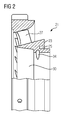
- the FIG. 2 shows a partial view of the inflow segment 21.
- perspective shown takes a view from the axis of rotation 2 in the radial direction to the outside.
- multiple inflow segment vanes 27 can be seen.
- the hub-side ring segment 23 is substantially triangular in shape and has the groove 25 for receiving the sealing element 24.
- the FIG. 2 shows a perspective of the inflow member 21, wherein an inside surface 33 of the hub side ring segment 23 can be seen.
- the outlet 34 of the holes 29 is formed on this inside surface 33.
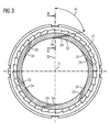
- FIG. 3 shows a sectional view through the inflow segment 21.
- inflow segment vane is designated by reference numeral 27.
- six holes 29 are executed, which are formed in a tangential direction to the discharge chamber 30 at an angle ⁇ .
- the direction of rotation of the rotor 3 is counterclockwise.
- the angle ⁇ is explained on the bore 29 in the twelve o'clock position. From the axis of rotation 2 from a reference line 35 is shown in the radial direction. At an angle ⁇ , which is between 40 ° and 80 °, a bore 29 is executed. Through this bore 29, the mass flow M 1 flows . Due to the applied twist of the steam undergoes a change in velocity and thus a reduction in the static temperature of the steam relative to the rotating system, which then leads to a cooling of the surface of the rotor 3 relative to the temperature of the mass flow M tot .
Landscapes
- Engineering & Computer Science (AREA)
- Mechanical Engineering (AREA)
- General Engineering & Computer Science (AREA)
- Physics & Mathematics (AREA)
- Fluid Mechanics (AREA)
- Turbine Rotor Nozzle Sealing (AREA)
- Structures Of Non-Positive Displacement Pumps (AREA)
Priority Applications (9)
| Application Number | Priority Date | Filing Date | Title |
|---|---|---|---|
| EP12176161.3A EP2685051A1 (de) | 2012-07-12 | 2012-07-12 | Einströmsegment für eine Strömungsmaschine |
| PCT/EP2013/064429 WO2014009333A1 (de) | 2012-07-12 | 2013-07-09 | Einströmsegment für eine strömungsmaschine |
| CN201380037173.4A CN104471193B (zh) | 2012-07-12 | 2013-07-09 | 用于流体机械的流入区段 |
| US14/413,310 US20150159486A1 (en) | 2012-07-12 | 2013-07-09 | Inflow segment for a turbomachine |
| PL13739171.0T PL2859192T3 (pl) | 2012-07-12 | 2013-07-09 | Segment wlotowy dla maszyny przepływowej |
| IN10499DEN2014 IN2014DN10499A (enExample) | 2012-07-12 | 2013-07-09 | |
| EP13739171.0A EP2859192B1 (de) | 2012-07-12 | 2013-07-09 | Einströmsegment für eine strömungsmaschine |
| JP2015520948A JP5985748B2 (ja) | 2012-07-12 | 2013-07-09 | ターボ機械のための流入セグメント |
| KR20157003409A KR20150036474A (ko) | 2012-07-12 | 2013-07-09 | 터보 기계의 유입 세그먼트 |
Applications Claiming Priority (1)
| Application Number | Priority Date | Filing Date | Title |
|---|---|---|---|
| EP12176161.3A EP2685051A1 (de) | 2012-07-12 | 2012-07-12 | Einströmsegment für eine Strömungsmaschine |
Publications (1)
| Publication Number | Publication Date |
|---|---|
| EP2685051A1 true EP2685051A1 (de) | 2014-01-15 |
Family
ID=48803516
Family Applications (2)
| Application Number | Title | Priority Date | Filing Date |
|---|---|---|---|
| EP12176161.3A Withdrawn EP2685051A1 (de) | 2012-07-12 | 2012-07-12 | Einströmsegment für eine Strömungsmaschine |
| EP13739171.0A Not-in-force EP2859192B1 (de) | 2012-07-12 | 2013-07-09 | Einströmsegment für eine strömungsmaschine |
Family Applications After (1)
| Application Number | Title | Priority Date | Filing Date |
|---|---|---|---|
| EP13739171.0A Not-in-force EP2859192B1 (de) | 2012-07-12 | 2013-07-09 | Einströmsegment für eine strömungsmaschine |
Country Status (8)
| Country | Link |
|---|---|
| US (1) | US20150159486A1 (enExample) |
| EP (2) | EP2685051A1 (enExample) |
| JP (1) | JP5985748B2 (enExample) |
| KR (1) | KR20150036474A (enExample) |
| CN (1) | CN104471193B (enExample) |
| IN (1) | IN2014DN10499A (enExample) |
| PL (1) | PL2859192T3 (enExample) |
| WO (1) | WO2014009333A1 (enExample) |
Families Citing this family (1)
| Publication number | Priority date | Publication date | Assignee | Title |
|---|---|---|---|---|
| DE102017114608A1 (de) * | 2017-06-30 | 2019-01-03 | Man Diesel & Turbo Se | Turbinenzuströmgehäuse einer Axialturbine eines Turboladers |
Citations (4)
| Publication number | Priority date | Publication date | Assignee | Title |
|---|---|---|---|---|
| US2294983A (en) * | 1941-04-29 | 1942-09-08 | Westinghouse Electric & Mfg Co | Steam turbine apparatus |
| US3429557A (en) * | 1966-06-30 | 1969-02-25 | Gen Electric | Steam turbine rotor cooling arrangement |
| JPH09125909A (ja) * | 1995-10-30 | 1997-05-13 | Mitsubishi Heavy Ind Ltd | 複合サイクル用蒸気タービン |
| EP2343443A2 (en) * | 2010-01-12 | 2011-07-13 | Kabushiki Kaisha Toshiba | Steam turbine |
Family Cites Families (7)
| Publication number | Priority date | Publication date | Assignee | Title |
|---|---|---|---|---|
| US3614255A (en) * | 1969-11-13 | 1971-10-19 | Gen Electric | Thrust balancing arrangement for steam turbine |
| US4242041A (en) * | 1979-01-15 | 1980-12-30 | Westinghouse Electric Corp. | Rotor cooling for double axial flow turbines |
| JPS59153901A (ja) * | 1983-02-21 | 1984-09-01 | Fuji Electric Co Ltd | 蒸気タ−ビンロ−タの冷却装置 |
| JPH0734808A (ja) * | 1993-07-26 | 1995-02-03 | Mitsubishi Heavy Ind Ltd | 蒸気タービン |
| JPH0742508A (ja) * | 1993-08-02 | 1995-02-10 | Mitsubishi Heavy Ind Ltd | 蒸気タービンのロータ冷却装置 |
| JP2004197696A (ja) * | 2002-12-20 | 2004-07-15 | Kawasaki Heavy Ind Ltd | 旋回ノズルを備えたガスタービン |
| CN100378308C (zh) * | 2006-07-07 | 2008-04-02 | 姜伟 | 叶轮加压转子喷射式燃气轮机 |
-
2012
- 2012-07-12 EP EP12176161.3A patent/EP2685051A1/de not_active Withdrawn
-
2013
- 2013-07-09 PL PL13739171.0T patent/PL2859192T3/pl unknown
- 2013-07-09 IN IN10499DEN2014 patent/IN2014DN10499A/en unknown
- 2013-07-09 US US14/413,310 patent/US20150159486A1/en not_active Abandoned
- 2013-07-09 KR KR20157003409A patent/KR20150036474A/ko not_active Withdrawn
- 2013-07-09 JP JP2015520948A patent/JP5985748B2/ja not_active Expired - Fee Related
- 2013-07-09 CN CN201380037173.4A patent/CN104471193B/zh not_active Expired - Fee Related
- 2013-07-09 EP EP13739171.0A patent/EP2859192B1/de not_active Not-in-force
- 2013-07-09 WO PCT/EP2013/064429 patent/WO2014009333A1/de not_active Ceased
Patent Citations (4)
| Publication number | Priority date | Publication date | Assignee | Title |
|---|---|---|---|---|
| US2294983A (en) * | 1941-04-29 | 1942-09-08 | Westinghouse Electric & Mfg Co | Steam turbine apparatus |
| US3429557A (en) * | 1966-06-30 | 1969-02-25 | Gen Electric | Steam turbine rotor cooling arrangement |
| JPH09125909A (ja) * | 1995-10-30 | 1997-05-13 | Mitsubishi Heavy Ind Ltd | 複合サイクル用蒸気タービン |
| EP2343443A2 (en) * | 2010-01-12 | 2011-07-13 | Kabushiki Kaisha Toshiba | Steam turbine |
Also Published As
| Publication number | Publication date |
|---|---|
| WO2014009333A1 (de) | 2014-01-16 |
| CN104471193A (zh) | 2015-03-25 |
| EP2859192B1 (de) | 2016-05-25 |
| IN2014DN10499A (enExample) | 2015-08-21 |
| KR20150036474A (ko) | 2015-04-07 |
| JP2015522130A (ja) | 2015-08-03 |
| EP2859192A1 (de) | 2015-04-15 |
| PL2859192T3 (pl) | 2016-11-30 |
| JP5985748B2 (ja) | 2016-09-06 |
| CN104471193B (zh) | 2016-08-24 |
| US20150159486A1 (en) | 2015-06-11 |
Similar Documents
| Publication | Publication Date | Title |
|---|---|---|
| DE102012013160B4 (de) | Labyrinthdichtungen | |
| EP2179143B1 (de) | Spaltkühlung zwischen brennkammerwand und turbinenwand einer gasturbinenanlage | |
| DE102015122928A1 (de) | Gasturbinendichtung | |
| EP2478188B1 (de) | Dichtungssegment für eine Strömungsmaschine | |
| WO2017029008A1 (de) | Rotorkühlung für eine dampfturbine | |
| EP2718545B1 (de) | Dampfturbine umfassend einen schubausgleichskolben | |
| EP2358979B1 (de) | Axialverdichter für eine gasturbine mit passiver radialspaltkontrolle | |
| EP3095957B1 (de) | Rotorscheibe zur verwendung in einem verdichter | |
| EP2802748B1 (de) | Strömungsmaschine mit schraubenkühlung | |
| EP2611992B1 (de) | Gehäuseseitige struktur einer turbomaschine | |
| EP2859192B1 (de) | Einströmsegment für eine strömungsmaschine | |
| EP2598724B1 (de) | Dampfturbine sowie verfahren zum kühlen einer solchen | |
| EP3034784A1 (de) | Kühlmöglichkeit für strömungsmaschinen | |
| DE102017109952A1 (de) | Rotorvorrichtung einer Strömungsmaschine | |
| EP3183426B1 (de) | Kontrollierte kühlung von turbinenwellen | |
| EP3536913A1 (de) | Innenring für eine turbomaschine und entsprechendes herstellungsverfahren | |
| DE102015110252A1 (de) | Statorvorrichtung für eine Strömungsmaschine mit einer Gehäuseeinrichtung und mehreren Leitschaufeln | |
| EP2453108B1 (de) | Rotor für eine Strömungsmaschine | |
| EP3445948B1 (de) | Dampfturbine | |
| EP3128135A1 (de) | Turbinendesign im überlasteinströmbereich | |
| DE102006015530A1 (de) | Turbomaschine | |
| DE4031620A1 (de) | Kompressoraufbau | |
| EP1905949A1 (de) | Kühlung eines Dampfturbinenbauteils | |
| EP2840229A1 (de) | Strömungsführung innerhalb einer Dampfturbinendichtung |
Legal Events
| Date | Code | Title | Description |
|---|---|---|---|
| PUAI | Public reference made under article 153(3) epc to a published international application that has entered the european phase |
Free format text: ORIGINAL CODE: 0009012 |
|
| AK | Designated contracting states |
Kind code of ref document: A1 Designated state(s): AL AT BE BG CH CY CZ DE DK EE ES FI FR GB GR HR HU IE IS IT LI LT LU LV MC MK MT NL NO PL PT RO RS SE SI SK SM TR |
|
| AX | Request for extension of the european patent |
Extension state: BA ME |
|
| STAA | Information on the status of an ep patent application or granted ep patent |
Free format text: STATUS: THE APPLICATION IS DEEMED TO BE WITHDRAWN |
|
| 18D | Application deemed to be withdrawn |
Effective date: 20140716 |