EP2685037A2 - Switching nut for a switch lock - Google Patents
Switching nut for a switch lock Download PDFInfo
- Publication number
- EP2685037A2 EP2685037A2 EP13003462.2A EP13003462A EP2685037A2 EP 2685037 A2 EP2685037 A2 EP 2685037A2 EP 13003462 A EP13003462 A EP 13003462A EP 2685037 A2 EP2685037 A2 EP 2685037A2
- Authority
- EP
- European Patent Office
- Prior art keywords
- nut
- lever
- bearing
- lock
- square opening
- Prior art date
- Legal status (The legal status is an assumption and is not a legal conclusion. Google has not performed a legal analysis and makes no representation as to the accuracy of the status listed.)
- Granted
Links
Images
Classifications
-
- E—FIXED CONSTRUCTIONS
- E05—LOCKS; KEYS; WINDOW OR DOOR FITTINGS; SAFES
- E05B—LOCKS; ACCESSORIES THEREFOR; HANDCUFFS
- E05B15/00—Other details of locks; Parts for engagement by bolts of fastening devices
- E05B15/0013—Followers; Bearings therefor
-
- E—FIXED CONSTRUCTIONS
- E05—LOCKS; KEYS; WINDOW OR DOOR FITTINGS; SAFES
- E05B—LOCKS; ACCESSORIES THEREFOR; HANDCUFFS
- E05B15/00—Other details of locks; Parts for engagement by bolts of fastening devices
- E05B15/16—Use of special materials for parts of locks
- E05B2015/1685—Sheet materials
-
- E—FIXED CONSTRUCTIONS
- E05—LOCKS; KEYS; WINDOW OR DOOR FITTINGS; SAFES
- E05B—LOCKS; ACCESSORIES THEREFOR; HANDCUFFS
- E05B59/00—Locks with latches separate from the lock-bolts or with a plurality of latches or lock-bolts
Definitions
- the invention relates to a sliding nut for a lock, with a square opening for inserting a square of a pusher, according to the preamble of claim 1.
- a sliding nut is a component that is provided in a switch lock and connected via a square with a pusher. By pressing the trigger, the switch nut is moved, with which various components of the lock are coupled. The closing or opening movement of the lock can then be initiated or controlled via the movement of the sliding nut.
- a split locknut is known in which a two-piece nut lever and the construction of the shift nut, a plurality of lock washers are provided.
- the nut lever and the individual lock washers consist of flat sheet sections, which are connected to each other via two bolts. About the bolt, the disc package, in which the individual discs rest on one another, riveted.
- To build the Wennnuss assembly a variety of flat sheet metal sections are required. This variety of disks required to construct the Heidelbergnuss assembly leads to an increase in manufacturing costs.
- Object of the present invention is therefore to provide a Wegnuss of the type mentioned for a lock available that can be easily and inexpensively manufactured.
- the bearing sections are also formed as flat plate sections.
- the realization of the bearing sections in the form of flat sheet sections offers two major advantages. On the one hand can in the production of the remaining flat sheet metal sections from the outset the Production of the storage sections are taken into account. These can in principle be produced in one operation with the other flat sheet metal sections. So there are, unlike the prior art, no separate round bolts required for attachment.
- the bearing plate sections according to the invention can have a beyond the mere attachment function of the nut lever and the individual discs further function, namely a construction function of the Wegnuss assembly.
- the flat plate section designed as a nut lever ultimately represents the functional basic element of the switch nut assembly.
- hooks, projections, interventions or the like can be provided on it or on its outer circumference corresponding switching and / or running surfaces.
- hooks, projections, interventions or the like can be provided on it or on its outer circumference corresponding switching and / or running surfaces.
- components such as springs, to be acted upon at the shift nut.
- openings, elongated holes or scenes for fastening or for actuating further components may be provided.
- the Wegnuss assembly has at least on one side a locking washer which is placed on the bearing sections.
- another lock washer is placed on the lock washer.
- the arrangement of a first and a further locking washer on each side of the nut lever is preferred.
- the embodiment according to the invention makes it possible, in a very simple manner, to change the sliding-nut assembly or to adapt it to another intended use.
- only one adapted to the other function nut lever must be used, while the remaining components can be used in the same form with even identical structure on. Ultimately, this significantly reduces the manufacturing costs.
- the nut lever has a corresponding square opening portion, which is part of the entire square opening of the Wegnuss assembly on.
- recesses are provided for the particular lateral insertion of the bearing plates in the nut lever.
- the recesses can be self-contained openings, that is to say independent of the square opening area. In this case, then have the bearing portions corresponding projections for engagement in these recesses.
- the recesses are provided on opposite sides of the square opening, thus opening into the square opening. In this case, at least one slot is then provided on the bearing section, so that the bearing section can be inserted into the recess via the slotted region.
- a slot is provided on opposite sides of the bearing portion, so that the bearing portion is slotted on both sides and thus rests on both sides in the edge region of the recess on the nut lever.
- the dimensions of the slot correspond to at least substantially the material thickness of the nut lever, so that there is an at least substantially play-free arrangement of the bearing plate.
- the formation of the recess and the bearing portion with the slots is otherwise such that the bearing portion in the installed state in a transverse plane arranged perpendicular to the plane of the nut lever and is held in a form-fitting manner in the transverse plane on the nut lever.
- the bearing section is arranged with respect to the square opening area so that it is parallel with its associated, the recess having surface of the square opening area with its flat plane.
- a web for engaging in a corresponding recess of the locking washer or the further locking washer is provided at the upper and / or lower end of the bearing portion.
- the recess can in principle again be a self-contained opening, which therefore does not open into another area.
- inner recesses are provided on opposite sides according to the arrangement of the bearing portions, which open into the square opening area: These inner recesses correspond to the relevant dimensions forth to the webs at the bearing sections.
- an outer recess is provided, which opens to the outside.
- a riveted connection is preferably provided.
- the outer end of the web is designed as a rivet.
- two rivet projections are provided for this purpose.
- the rivet projections are upset by vertical impact with a hammer or the like. By upsetting the rivet projections are wider until they are deformed over the edge of the recess and thereby press against the walls of the recess and the adjoining surface area of the outer lock washer. So that the riveted material of the rivet projections does not protrude as far as possible or only slightly beyond the plane of the outer lock washer, it is provided in a preferred embodiment that at least one recessed seat adjoins the respective recess laterally. The riveted material can then enter the depression.
- the recessed recording can be produced, for example, by a corresponding embossing of the respective locking washer.
- the individual lock washers and the nut lever are arranged parallel to each other, wherein the nut lever is spaced from the adjacent lock washer on the bearing portion. If two securing washers are provided on each side of the nut lever, they are preferably located directly opposite one another. In this case, the diameter of the further securing disk should be smaller than the diameter of the first securing disk, so that there is a shoulder which serves for fixing purposes in the housing of the lock.
- the flat plate portions are formed as punched parts which can be easily and inexpensively manufactured.
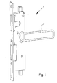
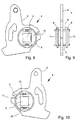
- a lock 1 embodied as a switch lock is shown, which has a pusher 2.
- the pusher 2 engages with a square, not shown in detail, in a square opening 3 in a square hole 3 Fig. 1 Not shown on a sliding nut.
- a switch lock it may be a switch lock, as for example from the DE 197 27 364 C1 or DE 10 2004 009 973 B4 is known.
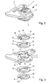
- the switching nut is ultimately made of a plurality of flat plate sections which are fixedly connected together to form a WegnussBaurios 4.
- the Heidelbergnuss assembly 4 has as a functional component and for coupling with other components of the switching mechanism 1, a nut lever 5 and further two bearing sections 6, 7, two first lock washers 8, 9 and two further lock washers 10, 11. All the above components are flat sheet metal sections, for example have been produced by punching. It is therefore ultimately punched flat sheet metal parts.
- the nut lever 5 has a square opening area 12. On two opposite sides recesses 13, 14 are provided, which open in the square opening area 12.
- the two bearing sections 6, 7 are provided on opposite side surfaces each with a slot 15, 16.
- the depth of the recesses 13, 14 is greater than the material thickness of the bearing sections 6, 7.
- the design and arrangement of the bearing sections 6, 7 in the recesses 13, 14 of the nut lever fifth is such that the bearing sections 6, 7 in the installed state (see. Fig. 2 ) are arranged in a transverse plane perpendicular to the plane of the nut lever 5 and are held in a form-fitting manner in the transverse plane on the nut lever 5.
- the flat sides of the bearing sections 6, 7 run at least substantially parallel to the associated sides of the square opening region 12.
- associated sides are understood to mean those sides which have the respective recess for the respective bearing section.
- Each of the bearing sections 6, 7 has at its upper end a protruding web 17 and at its lower end a protruding web 18.
- the webs 17, 18 are provided for engaging in corresponding recesses of the first locking washer 8, 9 and the further securing lock washer 10, 11. This will be discussed in more detail below.
- This has a square opening portion 19 with inner recesses 20, 21.
- the inner recesses 20, 21 open into the square opening region 19, the relevant dimensions of the square opening region 19 corresponding to the relevant dimensions of the square opening region 12 of the nut lever 5. Furthermore, the dimensions of the recesses 20, 21 correspond to the dimensions of the recesses 13, 14.
- Each of the further securing washers 10, 11 has a square opening area 22, which corresponds to the dimensions of the other square opening areas 12, 19 of the relevant dimensions forth from the outside on the first lock washer 8, 9 respectively.
- all square opening areas 12. 19, 22 form the square opening 3, in which the square of the pusher 2 engages, the other locking washer 10, 11 has moreover a smaller diameter than the first locking washer 8, 9, so that between the first locking washer 8, 9 and the further locking washer 10, 11 in the assembled state Paragraph results, which can serve for example for fixing purposes of the Wegnuss assembly 4 in the housing of the switch latch.
- outer recesses 23, 24 are provided on the outer side of the further securing disk 10, 11 on opposite sides.
- the outer recesses 23, 24 are each spaced by a web 25 of the square opening portion 22.
- the width of the web 25 plus the material thickness of the bearing sections 6, 7 corresponds to the depth of the recesses 13, 14 and the inner recesses 20, 21st
- the outer ends of the webs 17, 18 are each formed as a rivet, for this purpose, the outer ends of the webs 17, 18 are each provided with two projections which can be easily deformed.
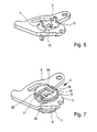
- the Fig. 7 to 10 is the state of the Wegnuss assembly 4 shown before the riveting process.
- the rivet projections protrude upwards.
- Fig. 9 shows, the nut lever 5 is parallel to the first lock washers 8, 9 and also arranged parallel to the other lock washers 10.
- Fig. 3 illustrates that the first lock washers 8, 9 are ultimately spaced from the nut lever 5 via the bearing sections 6, 7, while the further lock washers 10, 11 rest on the respective first lock washer 8, 9. Due to the spacing of the lock washers 8, 9 from the nut lever 5 due to the bearing sections 6, 7 results in a sufficiently high Nuss initial with comparatively few flat sheet sections.
- the riveted material is completely absorbed in the recessed receptacles 26 in the riveted state and does not over the outer sides of the further lock washers 10, 11 via (see. Fig. 2 ).
- the WegnussBauska 4 mirror-symmetrical to the plane of the nut lever 5, so it can be arranged right or left around.
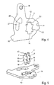
- the nut lever 5 itself has a contouring which is adapted to the respective lock purpose or the functions to be fulfilled. This can fundamentally vary considerably.
- the nut lever 5 has a freewheel portion 27 for a mandrel. Within the freewheeling area is a Entsperrnase 28 for the aforementioned mandrel.
- the nut lever 5 has an opening 29 for arranging a roller bearing.
- the nut lever 5 approximately opposite the opening 29, a nose 30 and approximately opposite the nose 30 has an outwardly open engagement 31 for the arrangement of a spring.
- the assembly of the Wegnuss assembly 4 is carried out such that after creation of the individual flat sheet sections, first the bearing sections 6, 7 are inserted into the corresponding recesses 13, 14. The material areas above and below the slots 15, 16 are then on the adjacent edges of the recesses 13, 14, as in Fig. 6 is shown. Subsequently, the first locking washers 8, 9 and the further securing washers 10, 11 are placed from above and below, so that then the in the Fig. 7 to 10 shown state results. Then, the ends of the four webs 17, 18 riveted, so that in Fig. 2 shown Heidelbergnuss assembly 4 results.
Landscapes
- Connection Of Plates (AREA)
- Mechanical Operated Clutches (AREA)
- Lock And Its Accessories (AREA)
- Seats For Vehicles (AREA)
- Push-Button Switches (AREA)
Abstract
Description
Die Erfindung betrifft eine Schaltnuss für ein Schloss, mit einer Vierkantöffnung zum Einsetzen eines Vierkants eines Drückers, nach dem Oberbegriff des Anspruchs 1.The invention relates to a sliding nut for a lock, with a square opening for inserting a square of a pusher, according to the preamble of
Schaltnüsse für Schlösser, insbesondere Schaltschlösser, sind aus der Praxis seit langem bekannt. Bei einer Schaltnuss handelt es sich um ein Bauteil, das in einem Schaltschloss vorgesehen und über einen Vierkant mit einem Drücker verbunden ist. Durch die Betätigung des Drückers wird die Schaltnuss bewegt, mit der verschiedene Bauteile des Schlosses gekoppelt sind. Über die Bewegung der Schaltnuss lässt sich dann die Schließ- bzw. Öffnungsbewegung des Schlosses einleiten bzw. steuern.Nuts for locks, especially switching locks, have long been known in practice. A sliding nut is a component that is provided in a switch lock and connected via a square with a pusher. By pressing the trigger, the switch nut is moved, with which various components of the lock are coupled. The closing or opening movement of the lock can then be initiated or controlled via the movement of the sliding nut.
Bekannte Schaltnüsse werden üblicherweise im Gussverfahren hergestellt. Es handelt sich damit um Gussteile. Zur Herstellung derartiger Guss-Schaltnüsse sind entsprechende Werkzeuge erforderlich, die vergleichsweise teuer sind, Dies ist gerade dann von Nachteil, wenn ein bestimmtes Schloss nur in geringen Stückzahlen zu produzieren ist.Known nuts are usually produced by casting. These are castings. For the production of such cast-iron nuts appropriate tools are required, which are relatively expensive, this is just then a disadvantage if a particular lock is to produce only in small quantities.
Aus der
Aufgabe der vorliegenden Erfindung ist es daher, eine Schaltnuss der eingangs genannten Art für ein Schloss zur Verfügung zu stellen, die einfach und kostengünstig hergestellt werden kann.Object of the present invention is therefore to provide a Schaltnuss of the type mentioned for a lock available that can be easily and inexpensively manufactured.
Bei der Erfindung ist nun vorgesehen, dass die Lagerabschnitte ebenfalls als Flachblechabschnitte ausgebildet sind. Die Realisierung der Lagerabschnitte in Form von Flachblechabschnitten bietet zwei wesentliche Vorteile. Zum einen kann bei der Herstellung der übrigen Flachblechabschnitte von vornherein die Herstellung der Lagerabschnitte berücksichtigt werden. Diese können grund-sätzlich in einem Arbeitsgang mit den anderen Flachblechabschnitten hergestellt werden. Es sind also, anders als beim Stand der Technik, keine separaten Rundbolzen zur Befestigung erforderlich. Dabei können die erfindungsgemäßen Lagerblechabschnitte eine über die reine Befestigungsfunktion des Nusshebels und der einzelnen Scheiben hinausgehende weitere Funktion, nämlich eine Aufbaufunktion der Schaltnuss-Baugruppe haben. Durch entsprechende Vorsprünge oder Schlitze an den Lagerabschnitten ist es möglich, dass der Nusshebel und die Sicherungsscheiben nicht unmittelbar aufeinander aufliegen, sondern über den Lagerabschnitt voneinander beabstandet sind. Auf diese Weise ergibt sich bevorzugt eine berührungsfreie Beabstandung der Sicherungsscheiben zum Nusshebel. Auf diese Weise können ergänzende Scheiben, die beim Stand der Technik zum Schaltnuss-Aufbau notwendig sind, entfallen. Somit kann bei der Erfindung schon bei der Herstellung ein gesamter Bausatz mit Lagerabschnitten, dem Nusshebel und den einzelnen Sicherungsscheiben zur Verfügung gestellt werden, ohne dass separate Nietbolzen erforderlich sind. Des Weiteren kann die Anzahl der notwenigen Teile zum Aufbau der Schaltnuss-Baugruppe durch die als Lagerabschnitte ausgebildeten Flachblechabschnitte reduziert werden.In the invention, it is now provided that the bearing sections are also formed as flat plate sections. The realization of the bearing sections in the form of flat sheet sections offers two major advantages. On the one hand can in the production of the remaining flat sheet metal sections from the outset the Production of the storage sections are taken into account. These can in principle be produced in one operation with the other flat sheet metal sections. So there are, unlike the prior art, no separate round bolts required for attachment. In this case, the bearing plate sections according to the invention can have a beyond the mere attachment function of the nut lever and the individual discs further function, namely a construction function of the Schaltnuss assembly. By appropriate projections or slots on the bearing portions, it is possible that the nut lever and the lock washers do not rest directly on each other, but are spaced from each other via the bearing portion. In this way, preferably results in a contact-free spacing of the lock washers to the nut lever. In this way, supplemental slices, which are necessary in the prior art for Schaltnuss structure omitted. Thus, in the invention, an entire kit with bearing sections, the nut lever and the individual lock washers can already be made available during production, without the need for separate rivet bolts. Furthermore, the number of necessary parts for constructing the Schaltnuss assembly can be reduced by the formed as a bearing sections flat plate sections.
Bei der erfindungsgemäßen Schaltnuss-Baugruppe stellt der als Nusshebel ausgebildeter Flachblechabschnitt letztlich das funktionale Grundelement der Schaltnuss-Baugruppe dar. An ihm bzw, an seinem Außenumfang können entsprechende Schalt- und bzw. Laufflächen, Haken, Vorsprünge, Eingriffe o. dgl. vorgesehen sein, um bei Bewegung des Nusshebels entsprechende Bewegungsabläufe im Schaltschloss zu initiieren bzw. Bauteile, wie Federn, an der Schaltnuss angreifen zu lassen. Des Weiteren können im Bereich des Nusshebels Öffnungen, Langlöcher oder Kulissen zur Befestigung bzw. zur Betätigung weiterer Bauteile vorgesehen sein.In the case of the inventive switch nut assembly, the flat plate section designed as a nut lever ultimately represents the functional basic element of the switch nut assembly. On it or on its outer circumference corresponding switching and / or running surfaces, hooks, projections, interventions or the like can be provided. in order to initiate corresponding motion sequences in the switch lock during movement of the nut lever or to allow components, such as springs, to be acted upon at the shift nut. Furthermore, in the region of the nut lever, openings, elongated holes or scenes for fastening or for actuating further components may be provided.
Weiterhin weist die Schaltnuss-Baugruppe zumindest auf einer Seite eine Sicherungsscheibe auf, die auf die Lagerabschnitte aufgesetzt ist. Bei einer bevorzugten Ausgestaltung ist auf die Sicherungsscheibe noch eine weitere Sicherungsscheibe aufgesetzt. Hinzuweisen ist darauf, dass es grundsätzlich bei entsprechender Ausbildung der Sicherungsscheibe auch möglich wäre, lediglich eine Sicherungsscheibe an der betreffenden Seite des Nusshebels vorzusehen. Bevorzugt ist jedoch die Anordnung einer ersten und einer weiteren Sicherungsscheibe auf jeder Seite des Nusshebels. Im Ergebnis weist die erfindungsgemäße Schaltnuss-Baugruppe bei der zuvor genannten bevorzugten Ausführungsform der Erfindung dann insgesamt sieben Bauteile, nämlich den Nusshebel, zwei Lagerabschnitte, zwei Sicherungsscheiben und zwei weitere Sicherungsscheiben auf.Furthermore, the Schaltnuss assembly has at least on one side a locking washer which is placed on the bearing sections. In a preferred embodiment, another lock washer is placed on the lock washer. It should be pointed out that it would also be possible in principle with appropriate design of the lock washer to provide only a lock washer on the relevant side of the nut lever. Preferably, however, the arrangement of a first and a further locking washer on each side of the nut lever. As a result, the inventive Schaltnuss assembly in the aforementioned preferred embodiment of the invention then a total of seven components, namely the nut lever, two bearing sections, two lock washers and two other lock washers.
Bei einer anderen sehr einfachen Ausgestaltung ist es grundsätzlich auch möglich, den Nusshebel als funktionales Bauteil, zwei Lagerabschnitte und nur eine einzige Sicherungsscheibe vorzusehen.In another very simple embodiment, it is in principle also possible to provide the nut lever as a functional component, two bearing sections and only a single locking washer.
Die erfindungsgemäße Ausgestaltung ermöglicht es im Übrigen in sehr einfacher Weise, die Schaltnuss-Baugruppe zu verändern bzw. an einen anderen Verwendungszweck anzupassen. Hierzu muss lediglich ein an die andere Funktion angepasster Nusshebel verwendet werden, während die übrigen Bauteile in gleicher Form mit sogar identischem Aufbau weiter verwendet werden können. Letztlich reduziert dies erheblich die Herstellungskosten.Incidentally, the embodiment according to the invention makes it possible, in a very simple manner, to change the sliding-nut assembly or to adapt it to another intended use. For this purpose, only one adapted to the other function nut lever must be used, while the remaining components can be used in the same form with even identical structure on. Ultimately, this significantly reduces the manufacturing costs.
Damit der Vierkant des Drückers den Nusshebel betätigen kann, weist der Nusshebel einen korrespondierenden Vierkantöffnungsbereich, der Teil der gesamten Vierkantöffnung der Schaltnuss-Baugruppe ist, auf. Darüber hinaus sind im Nusshebel Ausnehmungen zum insbesondere seitlichen Einsetzen der Lagerbleche vorgesehen. Bei den Ausnehmungen kann es sich um in sich geschlossene Öffnungen, also unabhängig von dem Vierkantöffnungsbereich, handeln. In diesem Fall weisen dann die Lagerabschnitte entsprechende Vorsprünge zum Eingriff in diese Ausnehmungen auf. Bevorzugt ist es aber, dass die Ausnehmungen an gegenüberliegenden Seiten der Vierkantöffnung vorgesehen sind, sich also in die Vierkantöffnung hinein öffnen. Hierbei ist dann am Lagerabschnitt wenigstens ein Schlitz vorgesehen, so dass der Lagerabschnitt über den geschlitzten Bereich in die Ausnehmung eingesetzt werden kann. Bevorzugt ist auf gegenüberliegenden Seiten des Lagerabschnitts jeweils ein Schlitz vorgesehen, so dass der Lagerabschnitt beidseitig geschlitzt ist und damit beidseitig im Randbereich der Ausnehmung an den Nusshebel anliegt. Die Abmaße des Schlitzes entsprechen dabei zumindest im Wesentlichen der Materialdicke des Nusshebels, so dass sich eine zumindest im Wesentlichen spielfreie Anordnung des Lagerblechs ergibt.So that the square of the pusher can operate the nut lever, the nut lever has a corresponding square opening portion, which is part of the entire square opening of the Schaltnuss assembly on. In addition, recesses are provided for the particular lateral insertion of the bearing plates in the nut lever. The recesses can be self-contained openings, that is to say independent of the square opening area. In this case, then have the bearing portions corresponding projections for engagement in these recesses. However, it is preferred that the recesses are provided on opposite sides of the square opening, thus opening into the square opening. In this case, at least one slot is then provided on the bearing section, so that the bearing section can be inserted into the recess via the slotted region. Preferably, a slot is provided on opposite sides of the bearing portion, so that the bearing portion is slotted on both sides and thus rests on both sides in the edge region of the recess on the nut lever. The dimensions of the slot correspond to at least substantially the material thickness of the nut lever, so that there is an at least substantially play-free arrangement of the bearing plate.
Die Ausbildung der Ausnehmung und des Lagerabschnitts mit den Schlitzen ist im Übrigen so, dass der Lagerabschnitt im Einbauzustand in einer Querebene senkrecht zur Ebene des Nusshebels angeordnet und formschlüssig in der Querebene am Nusshebel gehalten ist.The formation of the recess and the bearing portion with the slots is otherwise such that the bearing portion in the installed state in a transverse plane arranged perpendicular to the plane of the nut lever and is held in a form-fitting manner in the transverse plane on the nut lever.
Bevorzugt ist der Lagerabschnitt bezogen auf den Vierkantöffnungsbereich so angeordnet, dass er mit seiner Flachebene parallel zur zugeordneten, die Ausnehmung aufweisenden Fläche des Vierkantöffnungsbereichs ist.Preferably, the bearing section is arranged with respect to the square opening area so that it is parallel with its associated, the recess having surface of the square opening area with its flat plane.
Zur Verbindung des Lagerabschnitts mit der Sicherungsscheibe und/oder der weiteren Sicherungsscheibe ist am oberen und/oder unteren Ende des Lagerabschnitts ein Steg zum Eingreifen in eine korrespondierende Ausnehmung der Sicherungsscheibe bzw, der weiteren Sicherungsscheibe vorgesehen. Bei der Ausnehmung kann es sich grundsätzlich wiederum um eine in sich geschlossene Öffnung handeln, die sich also nicht in einen anderen Bereich hin öffnet.To connect the bearing portion with the locking washer and / or the further locking washer, a web for engaging in a corresponding recess of the locking washer or the further locking washer is provided at the upper and / or lower end of the bearing portion. The recess can in principle again be a self-contained opening, which therefore does not open into another area.
Bevorzugt ist es jedoch so, dass an der Sicherungsscheibe, die im Übrigen wie die weitere Sicherungsscheibe auch einen Vierkantöffnungsbereich aufweist, auf gegenüberliegenden Seiten entsprechend der Anordnung der Lagerabschnitte Innenausnehmungen vorgesehen sind, die sich in den Vierkantöffnungsbereich hin öffnen: Diese Innenausnehmungen korrespondieren von den relevanten Abmaßen her zu den Stegen an den Lagerabschnitten. Demgegenüber ist an der weiteren Sicherungsscheibe außenseitig am Umfang auf gegenüberliegenden Seiten jeweils eine Außenausnehmung vorgesehen, die sich nach außen hin öffnet.However, it is preferably the case that, on the securing disk, which also has a square opening area like the further securing disk, inner recesses are provided on opposite sides according to the arrangement of the bearing portions, which open into the square opening area: These inner recesses correspond to the relevant dimensions forth to the webs at the bearing sections. In contrast, on the other locking washer on the outside on the circumference on opposite sides in each case an outer recess is provided, which opens to the outside.
Letztlich ergibt sich durch die Realisierung der Innen- und Außenausnehmungen in der Sicherungsscheibe bzw. der weiteren Sicherungsscheibe eine Lagefixierung der Lagerabschnitte.Ultimately, results from the realization of the inner and outer recesses in the locking washer and the other locking washer a positional fixation of the bearing sections.
Zur Sicherung der Sicherungsscheiben auf den Lagerabschnitten ist bevorzugt eine Nietverbindung vorgesehen. Hierzu ist das äußere Ende des Steges als Niet ausgebildet. Bevorzugt sind zu diesem Zweck zwei Nietvorsprünge vorgesehen. Zur Herstellung der Nietverbindung werden die Nietvorsprünge durch senkrechte Schlage mit einem Hammer o. dgl. gestaucht. Durch das Stauchen werden die Nietvorsprünge breiter, bis sie über den Rand der Ausnehmung verformt werden und dabei gegen die Wandungen der Ausnehmung und den daran angrenzenden flächigen Bereich der äußeren Sicherungsscheibe drücken. Damit das vernietete Material der Nietvorsprünge möglichst nicht oder nur geringfügig über die Ebene der äußeren Sicherungsscheibe absteht, ist bei einer bevorzugten Ausführungsform vorgesehen, dass sich seitlich an die jeweilige Ausnehmung wenigstens eine vertiefte Aufnahme anschließt. In die Vertiefung kann dann das vernietete Material eintreten. Die vertiefte Aufnahme lässt sich beispielsweise durch eine entsprechende Prägung der betreffenden Sicherungsscheibe herstellen.To secure the lock washers on the bearing sections a riveted connection is preferably provided. For this purpose, the outer end of the web is designed as a rivet. Preferably, two rivet projections are provided for this purpose. To produce the riveted joint, the rivet projections are upset by vertical impact with a hammer or the like. By upsetting the rivet projections are wider until they are deformed over the edge of the recess and thereby press against the walls of the recess and the adjoining surface area of the outer lock washer. So that the riveted material of the rivet projections does not protrude as far as possible or only slightly beyond the plane of the outer lock washer, it is provided in a preferred embodiment that at least one recessed seat adjoins the respective recess laterally. The riveted material can then enter the depression. The recessed recording can be produced, for example, by a corresponding embossing of the respective locking washer.
Vom grundsätzlichen Aufbau ist es im Übrigen so, dass die einzelnen Sicherungsscheiben und der Nusshebel parallel zueinander angeordnet sind, wobei der Nusshebel von der benachbarten Sicherungsscheibe über den Lagerabschnitt beabstandet ist. Sind zwei Sicherungsscheiben auf jeder Seite des Nusshebels vorgesehen, liegen diese bevorzugt unmittelbar aufeinander auf. Dabei sollte der Durchmesser der weiteren Sicherungsscheibe geringer sein als der Durchmesser der ersten Sicherungsscheibe, so dass sich ein Absatz ergibt, der zu Fixierungszwecken im Gehäuse des Schlosses dient.From the basic structure, it is otherwise the case that the individual lock washers and the nut lever are arranged parallel to each other, wherein the nut lever is spaced from the adjacent lock washer on the bearing portion. If two securing washers are provided on each side of the nut lever, they are preferably located directly opposite one another. In this case, the diameter of the further securing disk should be smaller than the diameter of the first securing disk, so that there is a shoulder which serves for fixing purposes in the housing of the lock.
Im Übrigen ist es bei der vorliegenden Erfindung so, dass die Flachblechabschnitte als Stanzteile ausgebildet sind, die sich einfach und kostengünstig herstellen lassen.Incidentally, in the present invention, it is such that the flat plate portions are formed as punched parts which can be easily and inexpensively manufactured.
Letztlich lässt sich durch die Erfindung ohne Weiteres eine zur Ebene des Nusshebels spiegelsymmetrische Form der Schaltnuss-Baugruppe realisieren, so dass die erfindungsgemäße Schaltnuss sowohl für ein Rechts- als auch für ein Links-Schloss einsetzbar ist.Ultimately, can be realized by the invention readily to the plane of the nut lever mirror-symmetric shape of the Schaltnuss assembly, so that the invention Schaltnuss can be used for both a right and a left-lock.
Nachfolgend werden Ausführungsbeispiele der Erfindung anhand der Zeichnung erläutert. Dabei bilden alle beschriebenen und/oder bildlich dargestellten Merkmale für sich oder in beliebiger Kombination den Gegenstand der vorliegenden Erfindung, unabhängig von ihrer Zusammenfassung in den Ansprüchen oder deren Rückbeziehung. Es zeigt
- Fig. 1
- eine Darstellung eines eine erfindungsgemäße Schaltnuss-Baugruppe aufweisenden Schaltschlosses.
- Fig. 2
- eine perspektivische Ansicht einer erfindungsgemäßen Schaltnuss-Baugruppe,
- Fig. 3
- eine Explosionsdarstellung der erfindungsgemäßen Schaltnuss-Baugruppe,
- Fig. 4
- eine Darstellung eines Nusshebels der erfindungsgemäßen Schaltnuss-Baugruppe,
- Fig. 5
- eine Darstellung entsprechend
Fig. 4 mit angesetzten Lagerabschnitten, - Fig. 6
- eine Darstellung entsprechend
Fig. 5 mit eingesetzten Lagerabschnitten, - Fig. 7
- eine perspektivische Darstellung einer noch unvernieteten Schaltnuss-Baugruppe,
- Fig. 8
- eine Draufsicht der erfindungsgemäßen Schaltnuss-Baugruppe aus
Fig. 7 , - Fig. 9
- eine Seitenansicht der Schaltnuss-Baugruppe aus
Fig. 9 und - Fig. 10
- eine Unteransicht der Schaltnuss-Baugruppe aus
Fig. 8 .
- Fig. 1
- an illustration of an inventive Schaltnuss assembly having switching mechanism.
- Fig. 2
- a perspective view of a Schaltnuss assembly according to the invention,
- Fig. 3
- an exploded view of the invention Schaltnuss assembly,
- Fig. 4
- a representation of a nut lever of the invention Schaltnuss assembly,
- Fig. 5
- a representation accordingly
Fig. 4 with attached bearing sections, - Fig. 6
- a representation accordingly
Fig. 5 with inserted bearing sections, - Fig. 7
- a perspective view of a still riveted Schaltnuss assembly,
- Fig. 8
- a plan view of the invention Schaltnuss assembly
Fig. 7 . - Fig. 9
- a side view of the Schaltnuss assembly from
Fig. 9 and - Fig. 10
- a bottom view of the Schaltnuss assembly from
Fig. 8 ,
In
Wesentlich ist nun, dass die Schaltnuss letztlich aus einer Mehrzahl von Flachblechabschnitten hergestellt ist, die fest miteinander zu einer SchaltnussBaugruppe 4 verbunden sind. Die Schaltnuss-Baugruppe 4 weist als funktionales Bauteil und zur Kopplung mit weiteren Bauteilen des Schaltschlosses 1 einen Nusshebel 5 sowie weiterhin zwei Lagerabschnitte 6, 7, zwei erste Sicherungsscheiben 8, 9 und zwei weitere Sicherungsscheiben 10, 11 auf. Bei allen vorgenannten Bauteilen handelt es sich um Flachblechabschnitte, die beispielsweise durch Stanzen hergestellt worden sind. Es handelt sich also letztlich um gestanzte Flachblechteile.It is essential that the switching nut is ultimately made of a plurality of flat plate sections which are fixedly connected together to form a
Der Nusshebels 5 weist einen Vierkantöffnungsbereich 12 auf. An zwei gegenüberliegenden Seiten sind Ausnehmungen 13, 14 vorgesehen, die sich in die Vierkantöffnungsbereich 12 öffnen. Die beiden Lagerabschnitte 6, 7 sind an gegenüberliegenden Seitenflächen jeweils mit einem Schlitz 15, 16 versehen. Die Schlitzbreite entspricht dabei zumindest im Wesentlichen der Materialdicke des Nusshebels 5. Die Tiefe der Ausnehmungen 13, 14 ist dabei größer als die Materialdicke der Lagerabschnitte 6, 7. Die Ausbildung und Anordnung der Lagerabschnitte 6, 7 in den Ausnehmungen 13, 14 des Nusshebels 5 ist derart, dass die Lagerabschnitte 6, 7 im Einbauzustand (vgl.
Jeder der Lagerabschnitte 6, 7 weist an seinem oberen Ende einen abstehenden Steg 17 und an seinem unteren Ende einen abstehenden Steg 18 auf. Die Stege 17, 18 sind zum Eingreifen in korrespondierende Ausnehmungen der ersten Sicherungsscheibe 8, 9 und der weiteren Sicherungssicherungsscheibe 10, 11 vorgesehen. Hierauf wird nachfolgend noch näher eingegangen.Each of the bearing
Auf die Lagerabschnitte 6, 7 ober- und unterseitig aufgesetzt ist jeweils eine erste Sicherungsscheibe 8, 9. Diese weist einen Vierkantöffnungsbereich 19 mit Innenausnehmungen 20, 21 auf. Die Innenausnehmungen 20, 21 münden in den Vierkantöffnungsbereich 19, wobei die relevanten Abmaße des Vierkantöffnungsbereichs 19 den relevanten Abmaßen des Vierkantöffnungsbereichs 12 des Nusshebels 5 entsprechen. Des Weiteren entsprechen die Abmaße der Ausnehmungen 20, 21 den Abmaßen der Ausnehmungen 13, 14.On the bearing
Von außen auf die erste Sicherungsscheibe 8, 9 aufgesetzt ist jeweils die weitere Sicherungsscheibe 10, 11. Jede der weiteren Sicherungsscheiben 10, 11 weist einen Vierkantöffnungsbereich 22 auf, der von den relevanten Abmaßen her den Abmaßen der anderen Vierkantöffnungsbereiche 12, 19 entspricht. Letztlich bilden alle Vierkantöffnungsbereiche 12. 19, 22 die Vierkantöffnung 3, in die der Vierkant des Drückers 2 eingreift, Die weitere Sicherungsscheibe 10, 11 hat im Übrigen einen geringeren Durchmesser als die erste Sicherungsscheibe 8, 9, so dass sich zwischen der ersten Sicherungsscheibe 8, 9 und der weiteren Sicherungsscheibe 10, 11 im zusammengebauten Zustand ein Absatz ergibt, der beispielsweise zu Fixierungszwecken der Schaltnuss-Baugruppe 4 im Gehäuse des Schaltschlosses dienen kann.Each of the further securing
im Übrigen sind an der weiteren Sicherungsscheibe 10, 11 an gegenüberliegenden Seiten außenseitig am Umfang Außenausnehmungen 23, 24 vorgesehen. Die Außenausnehmungen 23, 24 sind jeweils über einen Steg 25 von dem Vierkantöffnungsbereich 22 beabstandet. Die Breite des Steges 25 zuzüglich der Materialdicke der Lagerabschnitte 6, 7 entspricht der Tiefe der Ausnehmungen 13, 14 sowie der Innenausnehmungen 20, 21.Incidentally,
Wie sich im Übrigen aus den einzelnen Figuren ergibt, sind die äußeren Enden der Stege 17, 18 jeweils als Niet ausgebildet, Hierzu sind die äußeren Enden der Stege 17, 18 jeweils mit zwei Vorsprüngen versehen, die sich leichter verformen lassen. In den
Beim Nietvorgang werden die Nietvorsprünge seitlich verformt. Von daher weisen die weiteren Sicherungsscheiben 10, 11 auf ihrer Außenseite benachbart von den Außenausnehmungen 23, 24 jeweils vertiefte Aufnahmen 26 auf.During riveting the rivet projections are deformed laterally. Therefore, the
Wie sich im Übrigen aus
Das vernietete Material ist im vernieteten Zustand vollständig in den vertieften Aufnahmen 26 aufgenommen und steht nicht über den Außenseiten der weiteren Sicherungsscheiben 10, 11 über (vgl.
Der Nusshebel 5 selbst weist eine Konturierung auf, die dem jeweiligen Schlosszweck bzw. den zu erfüllenden Funktionen angepasst ist. Dies kann grundsätzlich erheblich variieren. Bei der dargestellten Ausführungsform weist der Nusshebel 5 einen Freilaufbereich 27 für einen Dorn auf. Innerhalb des Freilaufbereichs befindet sich eine Entsperrnase 28 für den vorgenannten Dorn. Weiterhin weist der Nusshebel 5 eine Öffnung 29 zur Anordnung eines Rollenlagers auf. Des Weiteren weist der Nusshebel 5 etwa gegenüberliegend der Öffnung 29 eine Nase 30 und etwa gegenüberliegend der Nase 30 eine nach außen hin offenen Eingriff 31 zur Anordnung einer Feder auf.The
Der Zusammenbau der Schaltnuss-Baugruppe 4 erfolgt derart, dass nach Erstellung der einzelnen Flachblechabschnitte zunächst die Lagerabschnitte 6, 7 in die entsprechenden Ausnehmungen 13, 14 eingesetzt werden. Die Materialbereiche ober- und unterhalb der Schlitze 15, 16 liegen dann auf den benachbarten Rändern der Ausnehmungen 13, 14 auf, wie dies in
- 11
- Schlosslock
- 22
- Drückerhandle
- 33
- VierkantöffnungSquare hole
- 44
- Schaltnuss-BaugruppeSwitching nut assembly
- 55
- Nusshebelnut lever
- 66
- Lagerabschnittbearing section
- 77
- Lagerabschnittbearing section
- 88th
- Sicherungsscheibelock washer
- 99
- Sicherungsscheibelock washer
- 1010
- weitere Sicherungsscheibeanother lock washer
- 1111
- weitere Sicherungsscheibeanother lock washer
- 1212
- VierkantöffnungsbereichSquare opening area
- 1313
- Ausnehmungrecess
- 1414
- Ausnehmungrecess
- 1515
- Schlitzslot
- 1616
- Schlitzslot
- 1717
- Stegweb
- 1818
- Stegweb
- 1919
- VierkantöffnungsbereichSquare opening area
- 2020
- Innenausnehmunginner recess
- 2121
- Innenausnehmunginner recess
- 2222
- VierkantöffnungsbereichSquare opening area
- 2323
- AußenausnehmungAußenausnehmung
- 2424
- AußenausnehmungAußenausnehmung
- 2525
- Stegweb
- 2626
- vertiefte Aufnahmein-depth recording
- 2727
- FreilaufbereichFreewheel area
- 2828
- Entsperrnaseunlocking projection
- 2929
- OffnungOpening
- 3030
- Nasenose
- 3131
- Eingriffintervention
Claims (13)
dadurch gekennzeichnet,
dass die Lagerabschnitte (6, 7) als Flachblechabschnitte ausgebildet sind.A lock nut for a lock (1) having a square opening (3) for inserting a square of a pusher (2), wherein a plurality of flat plate portions fixedly connected to each other to a pusher assembly (4) are provided, and wherein the pusher assembly (4 ) Has at least one designed as a nut lever (5) flat plate portion, at least one as a locking washer (8, 9) formed flat plate portion and at least two bearing portions for supporting the nut lever (5) and the lock washer (8, 9).
characterized,
that the bearing portions (6, 7) are formed as flat sheet-metal sections.
Priority Applications (1)
| Application Number | Priority Date | Filing Date | Title |
|---|---|---|---|
| PL13003462T PL2685037T3 (en) | 2012-07-09 | 2013-07-09 | Switching nut for a switch lock |
Applications Claiming Priority (2)
| Application Number | Priority Date | Filing Date | Title |
|---|---|---|---|
| DE201210013476 DE102012013476A1 (en) | 2012-07-09 | 2012-07-09 | Switching nut for e.g. switching lock, has recess for insertion of bearing sections provided at sides of opening portion and opened to opening portion, and slot for insertion of bearing sections into recess provided at bearing sections |
| DE201210024820 DE102012024820A1 (en) | 2012-12-19 | 2012-12-19 | Switching nut for e.g. switching lock, has recess for insertion of bearing sections provided at sides of opening portion and opened to opening portion, and slot for insertion of bearing sections into recess provided at bearing sections |
Publications (3)
| Publication Number | Publication Date |
|---|---|
| EP2685037A2 true EP2685037A2 (en) | 2014-01-15 |
| EP2685037A3 EP2685037A3 (en) | 2015-01-14 |
| EP2685037B1 EP2685037B1 (en) | 2017-06-07 |
Family
ID=48790142
Family Applications (2)
| Application Number | Title | Priority Date | Filing Date |
|---|---|---|---|
| EP13003461.4A Not-in-force EP2685035B1 (en) | 2012-07-09 | 2013-07-09 | Switching nut for a lock or a striker box |
| EP13003462.2A Not-in-force EP2685037B1 (en) | 2012-07-09 | 2013-07-09 | Switching nut for a switch lock |
Family Applications Before (1)
| Application Number | Title | Priority Date | Filing Date |
|---|---|---|---|
| EP13003461.4A Not-in-force EP2685035B1 (en) | 2012-07-09 | 2013-07-09 | Switching nut for a lock or a striker box |
Country Status (2)
| Country | Link |
|---|---|
| EP (2) | EP2685035B1 (en) |
| PL (2) | PL2685037T3 (en) |
Families Citing this family (2)
| Publication number | Priority date | Publication date | Assignee | Title |
|---|---|---|---|---|
| DE202014006679U1 (en) * | 2014-08-20 | 2014-09-11 | Siegenia-Aubi Kg | Operating gear, in particular lock, for actuating a drive rod of a drive rod fitting for liftable and movable window or door leaves |
| US12006734B2 (en) * | 2021-06-18 | 2024-06-11 | Schlage Lock Company Llc | Rotation converter |
Citations (3)
| Publication number | Priority date | Publication date | Assignee | Title |
|---|---|---|---|---|
| DE472721C (en) | 1927-01-09 | 1929-03-05 | Ludw Rocholl & Co | Divided lock nut |
| DE19727364C1 (en) | 1997-06-27 | 1998-10-01 | Schlechtendahl & Soehne Wilh | Panic lock for emergency door |
| DE102004009973B4 (en) | 2004-03-01 | 2007-03-22 | Wilh. Schlechtendahl & Söhne GmbH & Co KG | Counter box for a panic door lock |
Family Cites Families (2)
| Publication number | Priority date | Publication date | Assignee | Title |
|---|---|---|---|---|
| GB690765A (en) * | 1950-12-23 | 1953-04-29 | Erebus Mfg Company Ltd | Followers for door locks or latches |
| NL6501567A (en) * | 1965-02-09 | 1966-08-10 |
-
2013
- 2013-07-09 PL PL13003462T patent/PL2685037T3/en unknown
- 2013-07-09 EP EP13003461.4A patent/EP2685035B1/en not_active Not-in-force
- 2013-07-09 EP EP13003462.2A patent/EP2685037B1/en not_active Not-in-force
- 2013-07-09 PL PL13003461T patent/PL2685035T3/en unknown
Patent Citations (3)
| Publication number | Priority date | Publication date | Assignee | Title |
|---|---|---|---|---|
| DE472721C (en) | 1927-01-09 | 1929-03-05 | Ludw Rocholl & Co | Divided lock nut |
| DE19727364C1 (en) | 1997-06-27 | 1998-10-01 | Schlechtendahl & Soehne Wilh | Panic lock for emergency door |
| DE102004009973B4 (en) | 2004-03-01 | 2007-03-22 | Wilh. Schlechtendahl & Söhne GmbH & Co KG | Counter box for a panic door lock |
Also Published As
| Publication number | Publication date |
|---|---|
| EP2685035A2 (en) | 2014-01-15 |
| EP2685035A3 (en) | 2015-01-14 |
| PL2685035T3 (en) | 2017-08-31 |
| EP2685037B1 (en) | 2017-06-07 |
| PL2685037T3 (en) | 2017-12-29 |
| EP2685037A3 (en) | 2015-01-14 |
| EP2685035B1 (en) | 2017-02-15 |
Similar Documents
| Publication | Publication Date | Title |
|---|---|---|
| DE202008018315U1 (en) | A vehicle | |
| EP2083136A2 (en) | Cylinder lock with plate tumblers and a key for the lock | |
| EP3136525A1 (en) | Cable conduit cover which can be walked on, cable conduit, and method for producing a cable conduit cover which can be walked on | |
| EP3280926A1 (en) | One-way roller clutch | |
| DE29724813U1 (en) | floor element | |
| EP2974945A1 (en) | Flap for a vehicle | |
| EP2685037B1 (en) | Switching nut for a switch lock | |
| EP1863990B1 (en) | Driving rod drive | |
| DE102012013476A1 (en) | Switching nut for e.g. switching lock, has recess for insertion of bearing sections provided at sides of opening portion and opened to opening portion, and slot for insertion of bearing sections into recess provided at bearing sections | |
| EP0838426A2 (en) | Door leaf, especially for elevators | |
| EP2754803A2 (en) | Espagnolette fitting for a window or a door | |
| DE2937609C2 (en) | ||
| EP3235984B1 (en) | Fitting for a window, method for producing the fitting and corresponding window | |
| DE202016007457U1 (en) | Rotary bolt lock | |
| EP4015869A1 (en) | Push resistant thrust chain actuated with chain transmission | |
| EP2626880B1 (en) | Switching unit for an electric switching device | |
| DE202012006525U1 (en) | Schaltnuss for a switch lock | |
| DE19607171C1 (en) | Lock plate for doors | |
| DE102012024820A1 (en) | Switching nut for e.g. switching lock, has recess for insertion of bearing sections provided at sides of opening portion and opened to opening portion, and slot for insertion of bearing sections into recess provided at bearing sections | |
| DE202008015517U1 (en) | Locking strip for a locking system with multiple locking | |
| EP3299531B1 (en) | Cover plate of a suspended ceiling with toolless operable locking element | |
| EP3486417A1 (en) | Lid positioning device | |
| EP2754802A2 (en) | Espagnolette fitting for a window or a door | |
| DE202012012142U1 (en) | Button nut for a lock or a counter box | |
| DE2010068A1 (en) | Housing for mounting and / or guiding a drive element for espagnolette fittings that can be moved by an operating handle |
Legal Events
| Date | Code | Title | Description |
|---|---|---|---|
| PUAI | Public reference made under article 153(3) epc to a published international application that has entered the european phase |
Free format text: ORIGINAL CODE: 0009012 |
|
| AK | Designated contracting states |
Kind code of ref document: A2 Designated state(s): AL AT BE BG CH CY CZ DE DK EE ES FI FR GB GR HR HU IE IS IT LI LT LU LV MC MK MT NL NO PL PT RO RS SE SI SK SM TR |
|
| AX | Request for extension of the european patent |
Extension state: BA ME |
|
| RIN1 | Information on inventor provided before grant (corrected) |
Inventor name: SCHRAMM, MARCEL Inventor name: KNICKENBERG, THOMAS |
|
| PUAL | Search report despatched |
Free format text: ORIGINAL CODE: 0009013 |
|
| AK | Designated contracting states |
Kind code of ref document: A3 Designated state(s): AL AT BE BG CH CY CZ DE DK EE ES FI FR GB GR HR HU IE IS IT LI LT LU LV MC MK MT NL NO PL PT RO RS SE SI SK SM TR |
|
| AX | Request for extension of the european patent |
Extension state: BA ME |
|
| RIC1 | Information provided on ipc code assigned before grant |
Ipc: E05B 15/16 20060101ALN20141210BHEP Ipc: E05B 15/00 20060101AFI20141210BHEP Ipc: E05B 59/00 20060101ALN20141210BHEP |
|
| 17P | Request for examination filed |
Effective date: 20150609 |
|
| RBV | Designated contracting states (corrected) |
Designated state(s): AL AT BE BG CH CY CZ DE DK EE ES FI FR GB GR HR HU IE IS IT LI LT LU LV MC MK MT NL NO PL PT RO RS SE SI SK SM TR |
|
| REG | Reference to a national code |
Ref country code: DE Ref legal event code: R079 Ref document number: 502013007410 Country of ref document: DE Free format text: PREVIOUS MAIN CLASS: E05C0007040000 Ipc: E05B0015000000 |
|
| GRAP | Despatch of communication of intention to grant a patent |
Free format text: ORIGINAL CODE: EPIDOSNIGR1 |
|
| RIC1 | Information provided on ipc code assigned before grant |
Ipc: E05B 59/00 20060101ALN20170310BHEP Ipc: E05B 15/00 20060101AFI20170310BHEP Ipc: E05B 15/16 20060101ALN20170310BHEP |
|
| INTG | Intention to grant announced |
Effective date: 20170407 |
|
| GRAS | Grant fee paid |
Free format text: ORIGINAL CODE: EPIDOSNIGR3 |
|
| AK | Designated contracting states |
Kind code of ref document: B1 Designated state(s): AL AT BE BG CH CY CZ DE DK EE ES FI FR GB GR HR HU IE IS IT LI LT LU LV MC MK MT NL NO PL PT RO RS SE SI SK SM TR |
|
| REG | Reference to a national code |
Ref country code: GB Ref legal event code: FG4D Free format text: NOT ENGLISH |
|
| GRAA | (expected) grant |
Free format text: ORIGINAL CODE: 0009210 |
|
| REG | Reference to a national code |
Ref country code: CH Ref legal event code: EP Ref country code: AT Ref legal event code: REF Ref document number: 899342 Country of ref document: AT Kind code of ref document: T Effective date: 20170615 |
|
| REG | Reference to a national code |
Ref country code: IE Ref legal event code: FG4D Free format text: LANGUAGE OF EP DOCUMENT: GERMAN |
|
| REG | Reference to a national code |
Ref country code: DE Ref legal event code: R096 Ref document number: 502013007410 Country of ref document: DE |
|
| REG | Reference to a national code |
Ref country code: FR Ref legal event code: PLFP Year of fee payment: 5 |
|
| REG | Reference to a national code |
Ref country code: NL Ref legal event code: MP Effective date: 20170607 |
|
| REG | Reference to a national code |
Ref country code: LT Ref legal event code: MG4D |
|
| PG25 | Lapsed in a contracting state [announced via postgrant information from national office to epo] |
Ref country code: FI Free format text: LAPSE BECAUSE OF FAILURE TO SUBMIT A TRANSLATION OF THE DESCRIPTION OR TO PAY THE FEE WITHIN THE PRESCRIBED TIME-LIMIT Effective date: 20170607 Ref country code: NO Free format text: LAPSE BECAUSE OF FAILURE TO SUBMIT A TRANSLATION OF THE DESCRIPTION OR TO PAY THE FEE WITHIN THE PRESCRIBED TIME-LIMIT Effective date: 20170907 Ref country code: HR Free format text: LAPSE BECAUSE OF FAILURE TO SUBMIT A TRANSLATION OF THE DESCRIPTION OR TO PAY THE FEE WITHIN THE PRESCRIBED TIME-LIMIT Effective date: 20170607 Ref country code: GR Free format text: LAPSE BECAUSE OF FAILURE TO SUBMIT A TRANSLATION OF THE DESCRIPTION OR TO PAY THE FEE WITHIN THE PRESCRIBED TIME-LIMIT Effective date: 20170908 Ref country code: LT Free format text: LAPSE BECAUSE OF FAILURE TO SUBMIT A TRANSLATION OF THE DESCRIPTION OR TO PAY THE FEE WITHIN THE PRESCRIBED TIME-LIMIT Effective date: 20170607 Ref country code: ES Free format text: LAPSE BECAUSE OF FAILURE TO SUBMIT A TRANSLATION OF THE DESCRIPTION OR TO PAY THE FEE WITHIN THE PRESCRIBED TIME-LIMIT Effective date: 20170607 |
|
| PGFP | Annual fee paid to national office [announced via postgrant information from national office to epo] |
Ref country code: DE Payment date: 20170720 Year of fee payment: 5 Ref country code: CH Payment date: 20170719 Year of fee payment: 5 Ref country code: FR Payment date: 20170724 Year of fee payment: 5 |
|
| PG25 | Lapsed in a contracting state [announced via postgrant information from national office to epo] |
Ref country code: SE Free format text: LAPSE BECAUSE OF FAILURE TO SUBMIT A TRANSLATION OF THE DESCRIPTION OR TO PAY THE FEE WITHIN THE PRESCRIBED TIME-LIMIT Effective date: 20170607 Ref country code: NL Free format text: LAPSE BECAUSE OF FAILURE TO SUBMIT A TRANSLATION OF THE DESCRIPTION OR TO PAY THE FEE WITHIN THE PRESCRIBED TIME-LIMIT Effective date: 20170607 Ref country code: LV Free format text: LAPSE BECAUSE OF FAILURE TO SUBMIT A TRANSLATION OF THE DESCRIPTION OR TO PAY THE FEE WITHIN THE PRESCRIBED TIME-LIMIT Effective date: 20170607 Ref country code: BG Free format text: LAPSE BECAUSE OF FAILURE TO SUBMIT A TRANSLATION OF THE DESCRIPTION OR TO PAY THE FEE WITHIN THE PRESCRIBED TIME-LIMIT Effective date: 20170907 Ref country code: RS Free format text: LAPSE BECAUSE OF FAILURE TO SUBMIT A TRANSLATION OF THE DESCRIPTION OR TO PAY THE FEE WITHIN THE PRESCRIBED TIME-LIMIT Effective date: 20170607 |
|
| PGFP | Annual fee paid to national office [announced via postgrant information from national office to epo] |
Ref country code: BE Payment date: 20170719 Year of fee payment: 5 |
|
| PG25 | Lapsed in a contracting state [announced via postgrant information from national office to epo] |
Ref country code: RO Free format text: LAPSE BECAUSE OF FAILURE TO SUBMIT A TRANSLATION OF THE DESCRIPTION OR TO PAY THE FEE WITHIN THE PRESCRIBED TIME-LIMIT Effective date: 20170607 Ref country code: EE Free format text: LAPSE BECAUSE OF FAILURE TO SUBMIT A TRANSLATION OF THE DESCRIPTION OR TO PAY THE FEE WITHIN THE PRESCRIBED TIME-LIMIT Effective date: 20170607 Ref country code: SK Free format text: LAPSE BECAUSE OF FAILURE TO SUBMIT A TRANSLATION OF THE DESCRIPTION OR TO PAY THE FEE WITHIN THE PRESCRIBED TIME-LIMIT Effective date: 20170607 Ref country code: CZ Free format text: LAPSE BECAUSE OF FAILURE TO SUBMIT A TRANSLATION OF THE DESCRIPTION OR TO PAY THE FEE WITHIN THE PRESCRIBED TIME-LIMIT Effective date: 20170607 |
|
| PG25 | Lapsed in a contracting state [announced via postgrant information from national office to epo] |
Ref country code: IS Free format text: LAPSE BECAUSE OF FAILURE TO SUBMIT A TRANSLATION OF THE DESCRIPTION OR TO PAY THE FEE WITHIN THE PRESCRIBED TIME-LIMIT Effective date: 20171007 Ref country code: IT Free format text: LAPSE BECAUSE OF FAILURE TO SUBMIT A TRANSLATION OF THE DESCRIPTION OR TO PAY THE FEE WITHIN THE PRESCRIBED TIME-LIMIT Effective date: 20170607 Ref country code: SM Free format text: LAPSE BECAUSE OF FAILURE TO SUBMIT A TRANSLATION OF THE DESCRIPTION OR TO PAY THE FEE WITHIN THE PRESCRIBED TIME-LIMIT Effective date: 20170607 |
|
| PGFP | Annual fee paid to national office [announced via postgrant information from national office to epo] |
Ref country code: PL Payment date: 20170720 Year of fee payment: 5 |
|
| REG | Reference to a national code |
Ref country code: DE Ref legal event code: R097 Ref document number: 502013007410 Country of ref document: DE |
|
| PG25 | Lapsed in a contracting state [announced via postgrant information from national office to epo] |
Ref country code: MC Free format text: LAPSE BECAUSE OF FAILURE TO SUBMIT A TRANSLATION OF THE DESCRIPTION OR TO PAY THE FEE WITHIN THE PRESCRIBED TIME-LIMIT Effective date: 20170607 |
|
| PLBE | No opposition filed within time limit |
Free format text: ORIGINAL CODE: 0009261 |
|
| STAA | Information on the status of an ep patent application or granted ep patent |
Free format text: STATUS: NO OPPOSITION FILED WITHIN TIME LIMIT |
|
| REG | Reference to a national code |
Ref country code: IE Ref legal event code: MM4A |
|
| PG25 | Lapsed in a contracting state [announced via postgrant information from national office to epo] |
Ref country code: IE Free format text: LAPSE BECAUSE OF NON-PAYMENT OF DUE FEES Effective date: 20170709 Ref country code: DK Free format text: LAPSE BECAUSE OF FAILURE TO SUBMIT A TRANSLATION OF THE DESCRIPTION OR TO PAY THE FEE WITHIN THE PRESCRIBED TIME-LIMIT Effective date: 20170607 |
|
| 26N | No opposition filed |
Effective date: 20180308 |
|
| GBPC | Gb: european patent ceased through non-payment of renewal fee |
Effective date: 20170907 |
|
| PG25 | Lapsed in a contracting state [announced via postgrant information from national office to epo] |
Ref country code: SI Free format text: LAPSE BECAUSE OF FAILURE TO SUBMIT A TRANSLATION OF THE DESCRIPTION OR TO PAY THE FEE WITHIN THE PRESCRIBED TIME-LIMIT Effective date: 20170607 |
|
| PG25 | Lapsed in a contracting state [announced via postgrant information from national office to epo] |
Ref country code: LU Free format text: LAPSE BECAUSE OF NON-PAYMENT OF DUE FEES Effective date: 20170709 |
|
| PG25 | Lapsed in a contracting state [announced via postgrant information from national office to epo] |
Ref country code: GB Free format text: LAPSE BECAUSE OF NON-PAYMENT OF DUE FEES Effective date: 20170907 |
|
| PG25 | Lapsed in a contracting state [announced via postgrant information from national office to epo] |
Ref country code: MT Free format text: LAPSE BECAUSE OF FAILURE TO SUBMIT A TRANSLATION OF THE DESCRIPTION OR TO PAY THE FEE WITHIN THE PRESCRIBED TIME-LIMIT Effective date: 20170607 |
|
| REG | Reference to a national code |
Ref country code: DE Ref legal event code: R119 Ref document number: 502013007410 Country of ref document: DE |
|
| REG | Reference to a national code |
Ref country code: CH Ref legal event code: PL |
|
| REG | Reference to a national code |
Ref country code: BE Ref legal event code: MM Effective date: 20180731 |
|
| PG25 | Lapsed in a contracting state [announced via postgrant information from national office to epo] |
Ref country code: DE Free format text: LAPSE BECAUSE OF NON-PAYMENT OF DUE FEES Effective date: 20190201 Ref country code: CH Free format text: LAPSE BECAUSE OF NON-PAYMENT OF DUE FEES Effective date: 20180731 Ref country code: FR Free format text: LAPSE BECAUSE OF NON-PAYMENT OF DUE FEES Effective date: 20180731 Ref country code: LI Free format text: LAPSE BECAUSE OF NON-PAYMENT OF DUE FEES Effective date: 20180731 |
|
| PG25 | Lapsed in a contracting state [announced via postgrant information from national office to epo] |
Ref country code: BE Free format text: LAPSE BECAUSE OF NON-PAYMENT OF DUE FEES Effective date: 20180731 |
|
| PG25 | Lapsed in a contracting state [announced via postgrant information from national office to epo] |
Ref country code: HU Free format text: LAPSE BECAUSE OF FAILURE TO SUBMIT A TRANSLATION OF THE DESCRIPTION OR TO PAY THE FEE WITHIN THE PRESCRIBED TIME-LIMIT; INVALID AB INITIO Effective date: 20130709 |
|
| REG | Reference to a national code |
Ref country code: AT Ref legal event code: MM01 Ref document number: 899342 Country of ref document: AT Kind code of ref document: T Effective date: 20180709 |
|
| PG25 | Lapsed in a contracting state [announced via postgrant information from national office to epo] |
Ref country code: CY Free format text: LAPSE BECAUSE OF NON-PAYMENT OF DUE FEES Effective date: 20170607 |
|
| PG25 | Lapsed in a contracting state [announced via postgrant information from national office to epo] |
Ref country code: MK Free format text: LAPSE BECAUSE OF FAILURE TO SUBMIT A TRANSLATION OF THE DESCRIPTION OR TO PAY THE FEE WITHIN THE PRESCRIBED TIME-LIMIT Effective date: 20170607 |
|
| PG25 | Lapsed in a contracting state [announced via postgrant information from national office to epo] |
Ref country code: AT Free format text: LAPSE BECAUSE OF NON-PAYMENT OF DUE FEES Effective date: 20180709 |
|
| PG25 | Lapsed in a contracting state [announced via postgrant information from national office to epo] |
Ref country code: PL Free format text: LAPSE BECAUSE OF NON-PAYMENT OF DUE FEES Effective date: 20180709 |
|
| PG25 | Lapsed in a contracting state [announced via postgrant information from national office to epo] |
Ref country code: TR Free format text: LAPSE BECAUSE OF FAILURE TO SUBMIT A TRANSLATION OF THE DESCRIPTION OR TO PAY THE FEE WITHIN THE PRESCRIBED TIME-LIMIT Effective date: 20170607 |
|
| PG25 | Lapsed in a contracting state [announced via postgrant information from national office to epo] |
Ref country code: PT Free format text: LAPSE BECAUSE OF FAILURE TO SUBMIT A TRANSLATION OF THE DESCRIPTION OR TO PAY THE FEE WITHIN THE PRESCRIBED TIME-LIMIT Effective date: 20170607 |
|
| PG25 | Lapsed in a contracting state [announced via postgrant information from national office to epo] |
Ref country code: AL Free format text: LAPSE BECAUSE OF FAILURE TO SUBMIT A TRANSLATION OF THE DESCRIPTION OR TO PAY THE FEE WITHIN THE PRESCRIBED TIME-LIMIT Effective date: 20170607 |