EP2685035A2 - Switching nut for a lock or a striker box - Google Patents
Switching nut for a lock or a striker box Download PDFInfo
- Publication number
- EP2685035A2 EP2685035A2 EP13003461.4A EP13003461A EP2685035A2 EP 2685035 A2 EP2685035 A2 EP 2685035A2 EP 13003461 A EP13003461 A EP 13003461A EP 2685035 A2 EP2685035 A2 EP 2685035A2
- Authority
- EP
- European Patent Office
- Prior art keywords
- bearing
- nut
- square opening
- sections
- lever
- Prior art date
- Legal status (The legal status is an assumption and is not a legal conclusion. Google has not performed a legal analysis and makes no representation as to the accuracy of the status listed.)
- Granted
Links
Images


Classifications
-
- E—FIXED CONSTRUCTIONS
- E05—LOCKS; KEYS; WINDOW OR DOOR FITTINGS; SAFES
- E05B—LOCKS; ACCESSORIES THEREFOR; HANDCUFFS
- E05B15/00—Other details of locks; Parts for engagement by bolts of fastening devices
- E05B15/0013—Followers; Bearings therefor
-
- E—FIXED CONSTRUCTIONS
- E05—LOCKS; KEYS; WINDOW OR DOOR FITTINGS; SAFES
- E05B—LOCKS; ACCESSORIES THEREFOR; HANDCUFFS
- E05B15/00—Other details of locks; Parts for engagement by bolts of fastening devices
- E05B15/16—Use of special materials for parts of locks
- E05B2015/1685—Sheet materials
-
- E—FIXED CONSTRUCTIONS
- E05—LOCKS; KEYS; WINDOW OR DOOR FITTINGS; SAFES
- E05B—LOCKS; ACCESSORIES THEREFOR; HANDCUFFS
- E05B59/00—Locks with latches separate from the lock-bolts or with a plurality of latches or lock-bolts
Definitions
- the invention relates to a sliding nut for a lock, with a square opening for inserting a square of a pusher, according to the preamble of claim 1.
- a Heidelbergnuss is a component which is provided in a switch lock / counter box and connected via a square with a pusher. By actuating the pusher the Wegnuss is moved, are coupled to the various components of the lock or counter box. About the movement of the Wegnuss can then Schriclev. Initiate or control the opening movement of the lock / counter box.
- a split locknut is known in which a two-piece nut lever and the construction of the shift nut, a plurality of lock washers are provided.
- the nut lever and the individual lock washers consist of flat sheet sections, which are connected to each other via two bolts.
- the disk package is riveted over the bolts.
- corresponding bolt openings are provided in the individual flat sheet sections.
- At least the two outer lock washers have slots for insertion of the bolts.
- Object of the present invention is therefore to provide a Wegnuss of the type mentioned for a lock or a mating box available, which can be easily and inexpensively.
- the invention provides that at least two sides of the square opening portion of the nut lever respectively a recess opening into the square opening region is provided for the lateral insertion of a bearing section and that a corresponding slot for lateral insertion of the bearing section into the recess is provided on the bearing section.
- the nut lever has the aforementioned square opening portion, which is part of the square opening of the Wegnuss assembly.
- the square opening region of the nut lever ultimately has four sides running at right angles.
- a recess for lateral insertion of a respective bearing section is provided on preferably three sides.
- To the recess corresponds to a slot in the central region of each bearing portion, so that the bearing portion can be inserted via the slot in the respective recess of the respective side of the square opening portion from the side.
- the bearing sections are designed as round bolts, which are provided only for fastening purposes.
- the bearing sections on the pure attachment function of the nut lever and the individual discs can perform an additional, other function, namely a construction function of the Wegnuss assembly.
- the flat plate section designed as a nut lever ultimately represents the functional basic element of the switch nut assembly.
- Appropriate switching and / or running surfaces, hooks, projections, interventions or the like can be provided on it or on its outer circumference. in order to initiate corresponding motion sequences in the switch lock during movement of the nut lever or to allow components, such as springs, to be acted upon at the shift nut.
- openings, elongated holes or scenes for fastening or for actuating further components may be provided.
- the Wegnuss assembly has at least two, in particular three or four bearing sections, which are preferably also flat sheets or sections.
- the bearing sections are used to build the Heidelbergnuss assembly in the transverse plane, ie perpendicular to the plane of the nut lever. It is so that the bearing sections are positively held on the nut lever.
- the Wegnuss assembly has on both sides of the nut lever each have a lock washer, which are placed on the end of the bearing sections and connected thereto.
- the inventive Wegtsnuss assembly in the aforementioned preferred embodiment of the invention then only six components, namely a nut lever, three bearing sections and two backup or bearing washers.
- the embodiment according to the invention makes it possible, in a very simple manner, to change the sliding-nut assembly or to adapt it to another intended use.
- only one adapted to the other function or use nut lever must be used, while the remaining components can be used in the same form with even identical structure on. Ultimately, this significantly reduces the manufacturing costs.
- the individual securing or bearing discs also each have a square opening area with four sides running at right angles. On each of the sides, a recess for connecting a bearing section is likewise provided, wherein a corresponding receiving area for receiving the securing or bearing disks is provided on the bearing section.
- the square opening portion of the nut lever corresponds at least substantially the square opening area of the respective safety or bearing washers.
- the four right angles extending sides of the square opening portion of the nut lever and the backup or bearing discs of the relevant dimensions match each other, so that when a square of a pusher, the forces transmitted via the pusher forces on all relevant components of Heidelbergnuss assembly to be transferred.
- the end provided receiving areas are provided on the bearing sections with an outer insertion through which the respective backup or bearing disc can be inserted into the receiving area ,
- the receiving area is then designed such that the securing or bearing disc after insertion into the receiving area and before the subsequent joining on all sides, i. on all four sides, engaged behind and thus fixed.
- the Wegnuss assembly is such that preferably each of the bearing portions protrudes with its slot opposite the edge in the square opening of the nut lever.
- the bearing portion is thus arranged with its flat plane transverse to the associated side of the square opening area. This refers to the side on which the recess of the square opening region is provided for the bearing section. In this case, then corresponds to the width of the recess in the nut lever at least substantially the thickness of the bearing portion.
- This arrangement of the bearing portion to the respective side of the square opening region ensures that ultimately only one such incision in the respective side is required for the recess, which corresponds approximately to the thickness of the bearing portion.
- joining projections are provided on the peripheral edge, which projects into the square opening region of the nut lever.
- joining projections are preferably provided in the region of the slot and in the region of the receiving areas.
- the joining projections are ultimately material projections whose material serves for joining in the direction of the slot for the connection of the relevant bearing section to the nut lever and on the other hand in the direction of the receiving areas for connecting the bearing section to the respective securing or bearing disc.
- the flat plate portions are formed as stamping or laser parts which can be easily and inexpensively manufactured.
- the invention makes it possible to realize a form of the sliding-nut assembly that is at least essentially mirror-symmetrical with respect to the level of the nut lever, so that the inventive sliding nut can be used both for a right-hand lock and for a left-hand lock or counter-lock.
- the present invention relates to a method for mounting a Wegnuss of the aforementioned type.
- the method is characterized in that the Heidelbergnuss is first pre-assembled.
- the bearing sections are inserted into the nut lever.
- the backup or bearing discs are inserted into the receiving areas of the bearing sections.
- a preassembled Heidelbergnuss This preassembled unit is then inserted into a joining tool.
- This joining tool has a joining opening, which opens into the square opening of the shift nut.
- a joining square mandrel is then driven through the square opening via the joining opening.
- the material of the joining projections is then displaced, which leads to the joining of the individual components together.
- Fig. 1 exemplified designed as a counter-box lock 1, which has a pusher 2.
- the pusher 2 engages with a square not shown in detail in a square opening 3 a in Fig. 1 Not shown on a sliding nut.
- it does not matter crucially here.
- it can be a lock, as it is for example from the DE 197 27 364 C1 or DE 10 2004 009 973 B4 is known.
- the shift nut is ultimately made of a plurality of flat sheet metal sections which are fixedly connected to each other to a Wegnuss assembly 4.
- the Heidelbergnuss assembly 4 as such in Fig. 2 is shown, has as a functional component and for coupling with other components of the lock 1, a nut lever 5, three bearing sections 6, 7, 8 and two lock washers 9, 10.
- the individual components are in Fig. 3 shown. All the above-mentioned components are flat sheet metal sections which have been produced, for example, by stamping / laser cutting. It is therefore ultimately punched or lasered flat sheet metal parts.
- the bearing sections 6, 7, 8, which are identical in construction, are, as will be discussed in more detail below, arranged in a transverse plane perpendicular to the plane of the nut lever 5 and, moreover, are held positively in the transverse plane on the nut lever 5.
- On both sides of the nut lever 5 is in each case one of the mutually identical locking washers 9, 10, which is connected to the end of the individual bearing sections 6, 7, 8.
- the nut lever 5 has a square opening region 11 with four sides 12, 13, 14, 15 extending at right angles. On three of the sides, namely on the sides 12, 13 and 14, a recess 16 is provided in each case, which opens into the square opening region 11. Each of the recesses 16 serves to insert one of the bearing sections 6, 7, 8. For this purpose, a slot 17 corresponding to the recess 16 is provided on each of the bearing sections 6, 7, 8. The dimensions of the recess 16 and the slot 17 are selected such that, after insertion of the respective bearing section, an at least substantially play-free arrangement or mounting of the respective bearing section on the nut lever 5 results.
- each of the backup or bearing washers 9, 10 also has a square opening portion 18 with four mutually perpendicular sides 19, 20, 21, 22.
- a recess 23 is provided in each case on three of the four sides, namely on the sides 19, 20 and 21.
- Each of the recesses 23 serves for the connection or for insertion of a corresponding bearing section 6, 7, 8.
- a receiving area 24, 25 is provided on each of the bearing sections 6, 7, 8 at the end, which accommodates the respective securing or bearing disks 9 , 10 serves.
- Each of the receiving areas 24, 25 has an insertion opening 26, via which the respective securing disk 9, 10 can be inserted into the respective receiving area 24, 25.
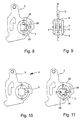
- the joining projections 28, 29 are each provided with run-on slopes, preferably in both directions. Incidentally, the joining projections 28, 29 protrude, as is the case in particular Fig. 8 results in the square opening 3 in the pre-assembled state.
- the nut lever 5 itself has a contouring which is adapted to the respective lock purpose or the functions to be fulfilled. This can fundamentally vary considerably.
- the nut lever 5 has a freewheeling area 30 for a mandrel. Within the freewheeling area 30 is a Entsperrnase 31 for the aforementioned mandrel.
- the nut lever 5 has an opening 32 for arranging a roller bearing. Furthermore, the nut lever 5 approximately opposite the opening 32, a nose 33 and approximately opposite the nose 33, a further opening 34 for the arrangement of a spring.
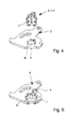
- the assembly of the Wegnuss assembly 4 will be described below with reference to Fig. 4 to 10 explained.
- the three bearing sections 6, 7, 8 the nut lever 5 supplied, as in Fig. 4 is shown.
- the bearing portions 6, 7, 8 are inserted via the respective slot 17 in the respective recess 16 of the square opening portion 11 of the nut lever 5, as shown in FIG Fig. 5 is shown.
- the two securing or bearing discs 9, 10 are supplied from above or below ( Fig. 6 ) and in the respective receiving areas 24, 25 of the bearing sections 6, 7, 8 used. It then results in the Fig.
- the preassembled unit is then inserted into a not shown joining tool in which the preassembled unit is fixed accordingly.
- the joining tool has a joining opening, which opens into the square opening 3 of the preassembled structural unit.
- the joint opening is continuous.
- a square-shaped joining mandrel corresponding to the dimensions of the square opening 3 is driven through.
- the square mandrel displaces the material of the joining projections 28, 29 in the direction of the slots 17 or the receiving areas 24, 25, so that the individual components are joined together. Subsequently, the results in the Fig.
- FIG. 11 another embodiment of a Wegnuss assembly according to the invention is shown, in the deviating from the in Fig. 11 illustrated embodiment, not three bearing sections 6, 7, 8 are provided, but are provided in the ultimately four bearing sections. There, opposite the bearing section 7, a further bearing section is provided. Thus, 4 bearing sections are provided on all four longitudinal sides of the square opening.
- the Wegnuss assembly 4 is at least substantially mirror-symmetrical to the plane of the nut lever 5, so it can be arranged and used right or left around.
- Switching nut assembly 34 opening 5 nut lever 6 bearing section 7 bearing section 8th bearing section 9
- Securing or bearing washers 10 Securing or bearing washers 11
Landscapes
- Connection Of Plates (AREA)
- Lock And Its Accessories (AREA)
- Mechanical Operated Clutches (AREA)
- Seats For Vehicles (AREA)
- Push-Button Switches (AREA)
Abstract
Description
Die Erfindung betrifft eine Schaltnuss für ein Schloss, mit einer Vierkantöffnung zum Einsetzen eines Vierkants eines Drückers, nach dem Oberbegriff des Anspruchs 1.The invention relates to a sliding nut for a lock, with a square opening for inserting a square of a pusher, according to the preamble of
Schaltnüsse für Schlösser oder Gegenkästen sind aus der Praxis seit langem bekannt. Bei einer Schaltnuss handelt es sich um ein Bauteil, das in einem Schaltschloss/Gegenkasten vorgesehen und über einen Vierkant mit einem Drücker verbunden ist. Durch die Betätigung des Drückers wird die Schaltnuss bewegt, mit der verschiedene Bauteile des Schlosses bzw. Gegenkastens gekoppelt sind. Über die Bewegung der Schaltnuss lässt sich dann die Schließbzw. Offnungsbewegung des Schlosses/Gegenkastens einleiten bzw. steuern.Nuts for locks or counter boxes have long been known in practice. A Schaltnuss is a component which is provided in a switch lock / counter box and connected via a square with a pusher. By actuating the pusher the Schaltnuss is moved, are coupled to the various components of the lock or counter box. About the movement of the Schaltnuss can then Schließbzw. Initiate or control the opening movement of the lock / counter box.
Bekannte Schaltnüsse werden üblicherweise im Gussverfahren hergestellt. Es handelt sich damit um Gussteile. Zur Herstellung derartiger Guss-Schaltnüsse sind entsprechende Werkzeuge erforderlich, die vergleichsweise teuer sind. Dies ist gerade dann von Nachteil, wenn ein bestimmtes Schloss nur in geringen Stückzahlen zu produzieren ist.Known nuts are usually produced by casting. These are castings. For the production of such cast-iron nuts corresponding tools are required, which are relatively expensive. This is particularly disadvantageous if a particular lock is only to be produced in small numbers.
Aus der
Aufgabe der vorliegenden Erfindung ist es daher, eine Schaltnuss der eingangs genannten Art für ein Schloss bzw. einen Gegenkasten zur Verfügung zu stellen, die einfach und kostengünstig hergestellt werden kann.Object of the present invention is therefore to provide a Schaltnuss of the type mentioned for a lock or a mating box available, which can be easily and inexpensively.
Zur Lösung der vorgenannten Aufgabe ist erfindungsgemäß vorgesehen, dass an wenigstens zwei Seiten des Vierkantöffnungsbereichs des Nusshebels jeweils eine sich in den Vierkantöffnungsbereich öffnende Ausnehmung zum seitlichen Einsetzen eines Lagerabschnitts vorgesehen ist und dass am Lagerabschnitt ein korrespondierender Schlitz zum seitlichen Einsetzen des Lagerabschnitts in die Ausnehmung vorgesehen ist.To achieve the above object, the invention provides that at least two sides of the square opening portion of the nut lever respectively a recess opening into the square opening region is provided for the lateral insertion of a bearing section and that a corresponding slot for lateral insertion of the bearing section into the recess is provided on the bearing section.
Damit der Vierkant des Drückers den Nusshebel betätigen kann, weist der Nusshebel den vorgenannten Vierkantöffnungsbereich auf, der Teil der Vierkantöffnung der Schaltnuss-Baugruppe ist. Dabei weist der Vierkantöffnungsbereich des Nusshebels letztlich vier rechtwinklig verlaufende Seiten auf. Zur Verbindung des Nusshebels mit den Lagerabschnitten ist an vorzugsweise drei Seiten jeweils eine Ausnehmung zum seitlichen Einsetzen jeweils eines Lagerabschnitts vorgesehen. Zu der Ausnehmung korrespondiert ein Schlitz im mittigen Bereich jedes Lagerabschnitts, so dass der Lagerabschnitt über den Schlitz in die betreffende Ausnehmung der jeweiligen Seite des Vierkantöffnungsbereichs von der Seite her eingesetzt werden kann.So that the square of the trigger can actuate the nut lever, the nut lever has the aforementioned square opening portion, which is part of the square opening of the Schaltnuss assembly. The square opening region of the nut lever ultimately has four sides running at right angles. To connect the nut lever to the bearing sections, a recess for lateral insertion of a respective bearing section is provided on preferably three sides. To the recess corresponds to a slot in the central region of each bearing portion, so that the bearing portion can be inserted via the slot in the respective recess of the respective side of the square opening portion from the side.
Durch die Realisierung der sich in den Vierkantöffnungsbereich öffnenden Ausnehmungen ist es möglich, die Lagerabschnitte nicht von oben her durch entsprechende Durchstecköffnungen in die vormontierte Baugruppe einzuschieben, sondern von der Seite her einzusetzen oder aber die gesamte Baugruppe ausgehend von den Lagerabschnitten auszubauen. Bei der erfindungsgemaßen Lösung ist es nicht erforderlich, dass die Lagerabschnitte als Rundbolzen ausgebildet sind, die lediglich zu Befestigungszwecken vorgesehen sind. Bei der Erfindung können die Lagerabschnitte über die reine Befestigungsfunktion des Nusshebels und der einzelnen Scheiben eine hinausgehende, weitere Funktion erfüllen, nämlich eine Aufbaufunktion der Schaltnuss-Baugruppe. Durch entsprechende Vorsprünge oder Schlitze an den Lagerabschnitten ist es möglich, dass der Nusshebel und die Sicherungsscheiben nicht unmittelbar aufeinander aufliegen, sondern über die Lagerabschnitte voneinander beabstandet sind. Auf diese Weise ergibt sich bevorzugt jeweils eine berührungsfreie Beabstandung der Sicherungsscheiben zum Nusshebel. Dies ist insbesondere deshalb möglich, da die Lagerabschnitte nicht durch das vormontierte Scheibenpaket hindurch gesteckt, sondern seitlich über den Vierkantöffnungsbereichs des Nusshebels bzw. die Vierkantöffnung insgesamt eingesetzt werden. Auf diese Weise können ergänzende Scheiben, die beim Stand der Technik zum Schaltnuss-Aufbau notwendig sind, entfallen. Die Erfindung bietet damit den wesentlichen Vorteil, dass die Anzahl der notwendigen Teile zum Aufbau der Schaltnuss-Baugruppe reduziert werden kann.By realizing the openings opening into the square opening region, it is possible not to insert the bearing sections from above through corresponding insertion openings into the preassembled subassembly, but to insert them from the side or to remove the entire subassembly starting from the bearing sections. In the inventive solution, it is not necessary that the bearing sections are designed as round bolts, which are provided only for fastening purposes. In the invention, the bearing sections on the pure attachment function of the nut lever and the individual discs can perform an additional, other function, namely a construction function of the Schaltnuss assembly. By appropriate projections or slots on the bearing sections, it is possible that the nut lever and the lock washers do not rest directly on each other, but are spaced from each other via the bearing sections. In this way, preferably results in each case a contact-free spacing of the lock washers to the nut lever. This is possible in particular because the bearing sections are not inserted through the preassembled disk pack, but rather are inserted laterally over the square opening area of the nut lever or the square opening as a whole. In this way, supplemental slices, which are necessary in the prior art for Schaltnuss structure omitted. The invention thus offers the significant advantage that the number of parts necessary for the construction of the Schaltnuss assembly can be reduced.
Bei der erfindungsgemäßen Schaltnuss-Baugruppe stellt der als Nusshebel ausgebildete Flachblechabschnitt letztlich das funktionale Grundelement der Schaltnuss-Baugruppe dar. An ihm bzw. an seinem Außenumfang können entsprechende Schalt- und bzw. Laufflächen, Haken, Vorsprünge, Eingriffe o. dgl. vorgesehen sein, um bei Bewegung des Nusshebels entsprechende Bewegungsabläufe im Schaltschloss zu initiieren bzw. Bauteile, wie Federn, an der Schaltnuss angreifen zu lassen. Des Weiteren können im Bereich des Nusshebels Öffnungen, Langlöcher oder Kulissen zur Befestigung bzw. zur Betätigung weiterer Bauteile vorgesehen sein.In the case of the inventive switch nut assembly, the flat plate section designed as a nut lever ultimately represents the functional basic element of the switch nut assembly. Appropriate switching and / or running surfaces, hooks, projections, interventions or the like can be provided on it or on its outer circumference. in order to initiate corresponding motion sequences in the switch lock during movement of the nut lever or to allow components, such as springs, to be acted upon at the shift nut. Furthermore, in the region of the nut lever, openings, elongated holes or scenes for fastening or for actuating further components may be provided.
Weiter weist die Schaltnuss-Baugruppe wenigstens zwei, insbesondere drei oder vier Lagerabschnitte auf, bei denen es sich bevorzugt ebenfalls um Flachbleche bzw. -abschnitte handelt. Die Lagerabschnitte dienen zum Aufbau der Schaltnuss-Baugruppe in der Querebene, also senkrecht zur Ebene des Nusshebels. Dabei ist es so, dass die Lagerabschnitte formschlüssig am Nusshebel gehalten sind.Next, the Schaltnuss assembly has at least two, in particular three or four bearing sections, which are preferably also flat sheets or sections. The bearing sections are used to build the Schaltnuss assembly in the transverse plane, ie perpendicular to the plane of the nut lever. It is so that the bearing sections are positively held on the nut lever.
Weiterhin weist die Schaltnuss-Baugruppe auf beiden Seiten des Nusshebels jeweils eine Sicherungsscheibe auf, die endseitig auf die Lagerabschnitte aufgesetzt und mit diesen verbunden sind. Im Ergebnis weist die erfindungsgemäße Schaltsnuss-Baugruppe bei der zuvor genannten bevorzugten Ausführungsform der Erfindung dann lediglich sechs Bauteile, nämlich einen Nusshebel, drei Lagerabschnitte und zwei Sicherungs- bzw. Lagerscheiben auf.Furthermore, the Schaltnuss assembly has on both sides of the nut lever each have a lock washer, which are placed on the end of the bearing sections and connected thereto. As a result, the inventive Schalttsnuss assembly in the aforementioned preferred embodiment of the invention then only six components, namely a nut lever, three bearing sections and two backup or bearing washers.
Die erfindungsgemäße Ausgestaltung ermöglicht es im Übrigen in sehr einfacher Weise, die Schaltnuss-Baugruppe zu verändern bzw. an einen anderen Verwendungszweck anzupassen. Hierzu muss lediglich ein an die andere Funktion bzw. Verwendung angepasster Nusshebel eingesetzt werden, während die übrigen Bauteile in gleicher Form mit sogar identischem Aufbau weiter verwendet werden können. Letztlich reduziert dies erheblich die Herstellungskosten.Incidentally, the embodiment according to the invention makes it possible, in a very simple manner, to change the sliding-nut assembly or to adapt it to another intended use. For this purpose, only one adapted to the other function or use nut lever must be used, while the remaining components can be used in the same form with even identical structure on. Ultimately, this significantly reduces the manufacturing costs.
Die einzelnen Sicherungs- bzw. Lagerscheiben weisen jeweils ebenfalls einen Vierkantöffnungsbereich mit vier rechtwinklig verlaufenden Seiten auf. An jeder der Seiten ist ebenfalls eine Ausnehmung zur Verbindung eines Lagerabschnitts vorgesehen, wobei am Lagerabschnitt ein korrespondierender Aufnahmebereich zur Aufnahme der Sicherungs- bzw. Lagerscheiben vorgesehen ist. Somit entspricht der Vierkantöffnungsbereich des Nusshebels zumindest im Wesentlichen dem Vierkantöffnungsbereich der jeweiligen Sicherungs- bzw. Lagerscheiben. Wichtig in diesem Zusammenhang ist, dass die vier rechtwinklig verlaufenden Seiten des Vierkantöffnungsbereichs des Nusshebels und der Sicherungs- bzw. Lagerscheiben von den relevanten Abmaßen her einander entsprechen, so dass bei einem eingesetzten Vierkant eines Drücker die über den Drücker übertragenen Kräfte auf alle relevanten Bauteile der Schaltnuss-Baugruppe übertragen werden.The individual securing or bearing discs also each have a square opening area with four sides running at right angles. On each of the sides, a recess for connecting a bearing section is likewise provided, wherein a corresponding receiving area for receiving the securing or bearing disks is provided on the bearing section. Thus, the square opening portion of the nut lever corresponds at least substantially the square opening area of the respective safety or bearing washers. Important in this context is that the four right angles extending sides of the square opening portion of the nut lever and the backup or bearing discs of the relevant dimensions match each other, so that when a square of a pusher, the forces transmitted via the pusher forces on all relevant components of Schaltnuss assembly to be transferred.
Um eine hinreichende Fixierung der Sicherungs- bzw. Lagerscheiben bei der Vormontage der erfindungsgemäßen Schaltnuss-Baugruppe zu erzielen, sind die endseitig vorgesehenen Aufnahmebereiche an den Lagerabschnitten mit einer äußeren Einsetzöffnung versehen, über die die jeweilige Sicherungs- bzw. Lagerscheibe in den Aufnahmebereich eingesetzt werden kann. Der Aufnahmebereich ist dabei dann derart ausgebildet, dass die Sicherungs- bzw. Lagerscheibe nach dem Einsetzen in den Aufnahmebereich und vor dem anschließenden Fügen allseitig, d.h. an allen vier Seiten, hintergriffen und damit fixiert ist.In order to achieve a sufficient fixation of the backup or bearing discs in the pre-assembly of the invention Schaltnuss assembly, the end provided receiving areas are provided on the bearing sections with an outer insertion through which the respective backup or bearing disc can be inserted into the receiving area , The receiving area is then designed such that the securing or bearing disc after insertion into the receiving area and before the subsequent joining on all sides, i. on all four sides, engaged behind and thus fixed.
Bei der erfindungsgemäßen Ausgestaltung der Schaltnuss-Baugruppe ist es so, dass bevorzugt jeder der Lagerabschnitte mit seiner dem Schlitz gegenüber liegenden Randkante in die Vierkantöffnung des Nusshebels ragt. Der Lagerabschnitt ist damit mit seiner Flachebene quer zur zugeordneten Seite des Vierkantöffnungsbereich angeordnet. Damit ist die Seite gemeint, an der die Ausnehmung des Vierkantöffnungsbereichs für den Lagerabschnitt vorgesehen ist. Dabei entspricht dann die Breite der Ausnehmung im Nusshebel zumindest im Wesentlichen der Dicke des Lagerabschnitts. Durch diese Anordnung des Lagerabschnitts zur jeweiligen Seite des Vierkantöffnungsbereichs ist sichergestellt, dass für die Ausnehmung letztlich nur ein solcher Einschnitt in der jeweiligen Seite erforderlich ist, die etwa der Dicke des Lagerabschnitts entspricht. Dies hat zur Folge, dass die verbleibenden Bereiche der jeweiligen Seite noch hinreichend groß sind, um die über den Vierkant des Drückers beim Betätigen auftretenden Kräfte gut aufnehmen zu können. Eine derartige Kraftaufnahme könnte dann in Frage gestellt sein, wenn der Lagerabschnitt letztlich nicht rechtwinklig zur betreffenden Seite, sondern parallel zu dieser angeordnet wäre, also eine vergleichsweise große Ausnehmung im Nusshebel für den Lagerabschnitt erforderlich wäre. Durch die erfindungsgemäße Anordnung der Lagerabschnitte am Nusshebel lässt sich, wie bei Versuchen festgestellt worden sind, eine Schaltnuss-Baugruppe zur Verfügung stellen, die höchsten Belastungen standhält.In the embodiment of the invention, the Schaltnuss assembly is such that preferably each of the bearing portions protrudes with its slot opposite the edge in the square opening of the nut lever. The bearing portion is thus arranged with its flat plane transverse to the associated side of the square opening area. This refers to the side on which the recess of the square opening region is provided for the bearing section. In this case, then corresponds to the width of the recess in the nut lever at least substantially the thickness of the bearing portion. This arrangement of the bearing portion to the respective side of the square opening region ensures that ultimately only one such incision in the respective side is required for the recess, which corresponds approximately to the thickness of the bearing portion. This has the consequence that the remaining areas of the respective side are still sufficiently large to be able to absorb the forces occurring on the square of the pusher when pressed well. Such a force absorption could then be called into question if the bearing section would ultimately not be arranged at right angles to the relevant side but parallel to it, ie a comparatively large recess in the nut lever would be required for the bearing section. The inventive arrangement of the bearing sections on the nut lever can be found, as in experiments, provide a sliding nut assembly that can withstand the highest loads.
Bei einer besonders bevorzugten Ausgestaltung der Erfindung ist an der Randkante, die in den Vierkantöffnungsbereich des Nusshebels ragt, wenig-stens ein Fügevorsprung vorgesehen. Bevorzugt sind im Bereich des Schlitzes sowie im Bereich der Aufnahmebereiche jeweils Fügevorsprünge vorgesehen. Bei den Fügevorsprüngen handelt es sich letztlich um Materialvorsprünge, deren Material beim Fügen in Richtung einerseits des Schlitzes zur Verbindung des betreffenden Lagerabschnitts mit dem Nusshebel und andererseits in Richtung der Aufnahmebereiche zur Verbindung des Lagerabschnitts mit der jeweiligen Sicherungs- bzw. Lagerscheibe dienen.In a particularly preferred embodiment of the invention, at least one joining projection is provided on the peripheral edge, which projects into the square opening region of the nut lever. In each case joining projections are preferably provided in the region of the slot and in the region of the receiving areas. The joining projections are ultimately material projections whose material serves for joining in the direction of the slot for the connection of the relevant bearing section to the nut lever and on the other hand in the direction of the receiving areas for connecting the bearing section to the respective securing or bearing disc.
Vom grundsätzlichen Aufbau ist es im Übrigen so, dass die einzelnen Sicherungs- bzw. Lagerscheiben und der Nusshebel parallel zueinander angeordnet sind, wobei der Nusshebel von der benachbarten Sicherungs- bzw. Lagerscheibe über einen Bereich des Lagerabschnitts beabstandet ist.From the basic structure, it is otherwise the case that the individual securing or bearing discs and the nut lever are arranged parallel to each other, wherein the nut lever is spaced from the adjacent backup or bearing disc over a portion of the bearing portion.
Im Übrigen ist es bei der vorliegenden Erfindung so, dass die Flachblechabschnitte als Stanz-oder Laserteile ausgebildet sind, die sich einfach und kostengünstig herstellen lassen.Incidentally, in the present invention, it is such that the flat plate portions are formed as stamping or laser parts which can be easily and inexpensively manufactured.
Letztlich lässt sich durch die Erfindung eine zur Ebene des Nusshebels zumindest im Wesentlichen spiegelsymmetrische Form der Schaltnuss-Baugruppe realisieren, so dass die erfindungsgemäße Schaltnuss sowohl für ein Rechts- als auch für ein Links-Schloss bzw. Gegenkasten einsetzbar ist.Finally, the invention makes it possible to realize a form of the sliding-nut assembly that is at least essentially mirror-symmetrical with respect to the level of the nut lever, so that the inventive sliding nut can be used both for a right-hand lock and for a left-hand lock or counter-lock.
Darüber hinaus betrifft die vorliegende Erfindung ein Verfahren zur Montage einer Schaltnuss der vorgenannten Art. Das Verfahren zeichnet sich dadurch aus, dass die Schaltnuss zunächst vormontiert wird. Hierzu werden die Lagerabschnitte in den Nusshebel eingesetzt. Anschließend werden die Sicherungs- bzw. Lagerscheiben in die Aufnahmebereiche der Lagerabschnitte eingesetzt. Auf diese Weise ergibt sich eine vormontierte Schaltnuss. Diese vormontierte Einheit wird anschließend in ein Fügewerkzeug eingesetzt. Dieses Fügewerkzeug weist eine Fügeöffnung auf, die in die Vierkantöffnung der Schaltnuss mündet. Über die Fügeöffnung wird dann ein Fügevierkantdorn durch die Vierkantöffnung getrieben. Dabei wird das Material der Fügevorsprünge dann verdrängt, was zur Fügung der einzelnen Bauteile miteinander führt.Moreover, the present invention relates to a method for mounting a Schaltnuss of the aforementioned type. The method is characterized in that the Schaltnuss is first pre-assembled. For this purpose, the bearing sections are inserted into the nut lever. Subsequently, the backup or bearing discs are inserted into the receiving areas of the bearing sections. In this way, a preassembled Schaltnuss. This preassembled unit is then inserted into a joining tool. This joining tool has a joining opening, which opens into the square opening of the shift nut. A joining square mandrel is then driven through the square opening via the joining opening. The material of the joining projections is then displaced, which leads to the joining of the individual components together.
Nachfolgend werden Ausführungsbeispiele der Erfindung anhand der Zeichnung erläutert. Dabei bilden alle beschriebenen und/oder bildlich dargestellten Merkmale für sich oder in beliebiger Kombination den Gegenstand der vorliegenden Erfindung, unabhängig von ihrer Zusammenfassung in den Ansprüchen oder deren Rückbeziehung. Es zeigt
- Fig. 1
- eine Darstellung eines eine erfindungsgemäße SchaltnussBaugruppe aufweisenden Gegenkastens.
- Fig. 2
- eine perspektivische Ansicht einer erfindungsgemäßen Schaltnuss-Baugruppe im fertig montierten Zustand,
- Fig. 3
- eine Draufsicht auf die einzelnen Baugruppenelemente der erfindungsgemäßen Schaltnuss-Baugruppe,
- Fig. 4
- eine perspektivische Darstellung eines Nusshebels mit drei anzusetzenden Lagerabschnitten,
- Fig. 5
- eine perspektivische Darstellung des Nusshebels mit eingesetzten Lagerabschnitten,
- Fig. 6
- eine perspektivische Darstellung des Nusshebels aus
Fig. 5 mit anzusetzenden Sicherungs- bzw. Lagerscheiben, - Fig. 7
- eine perspektivische Darstellung einer vormontierten Schaltnuss-Baugruppe,
- Fig. 8
- eine Draufsicht auf die vormontierte Schaltnuss-Baugruppe aus
Fig. 7 , - Fig. 9
- eine Seitenansicht der vormontierten Schaltnuss-Baugruppe aus
Fig. 7 , - Fig. 10
- eine Draufsicht auf die fertig montierte Schaltnuss-Baugruppe entsprechend
Fig. 2 und - Fig. 11
- eine Draufsicht auf eine andere Ausführungsform einer erfindungsgemäßen Schaltnuss-Baugruppe.
- Fig. 1
- a representation of a invention a SchaltnussBaugruppe having counter box.
- Fig. 2
- a perspective view of a Schaltnuss assembly according to the invention in the assembled state,
- Fig. 3
- a plan view of the individual assembly elements of the invention Schaltnuss assembly,
- Fig. 4
- a perspective view of a nut lever with three bearing sections to be applied,
- Fig. 5
- a perspective view of the nut lever with inserted bearing sections,
- Fig. 6
- a perspective view of the nut lever
Fig. 5 with securing or bearing washers to be attached, - Fig. 7
- a perspective view of a preassembled Schaltnuss assembly,
- Fig. 8
- a plan view of the preassembled Schaltnuss assembly from
Fig. 7 . - Fig. 9
- a side view of the preassembled Schaltnuss assembly from
Fig. 7 . - Fig. 10
- a plan view of the finished assembled Schaltnuss assembly accordingly
Fig. 2 and - Fig. 11
- a plan view of another embodiment of a Schaltnuss assembly according to the invention.
In
Wesentlich ist nun, dass die Schaltnuss letztlich aus einer Mehrzahl von Flachblechabschnitten hergestellt ist, die fest miteinander zu einer Schaltnuss-Baugruppe 4 verbunden sind. Die Schaltnuss-Baugruppe 4, die als solche in
Die Lagerabschnitte 6, 7, 8, die jeweils baugleich sind, sind, worauf nachfolgend noch näher eingegangen wird, in einer Querebene senkrecht zur Ebene des Nusshebels 5 angeordnet und sind im Übrigen formschlüssig in der Querebene am Nusshebel 5 gehalten. Beidseitig des Nusshebels 5 befindet sich dabei jeweils eine der zueinander baugleichen Sicherungsscheiben 9, 10, die mit den einzelnen Lagerabschnitten 6, 7, 8 endseitig verbunden ist.The bearing
Der Nusshebel 5 weist einen Vierkantöffnungsbereich 11 mit vier rechtwinklig verlaufenden Seiten 12, 13, 14, 15 auf. An drei der Seiten, nämlich an den Seiten 12, 13 und 14, ist jeweils eine Ausnehmung 16 vorgesehen, die sich in den Vierkantöffnungsbereich 11 öffnet. Jede der Ausnehmungen 16 dient zum Einsetzen eines der Lagerabschnitte 6, 7, 8. Hierzu ist an jedem der Lagerabschnitte 6. 7, 8 ein zur Ausnehmung 16 korrespondierender Schlitz 17 vorgesehen. Die Abmaße der Ausnehmung 16 und des Schlitzes 17 sind derart gewählt, dass sich nach Einsetzen des betreffenden Lagerabschnitts eine zumindest im Wesentlichen spielfreie Anordnung bzw. Halterung des jeweiligen Lagerabschnitts am Nusshebel 5 ergibt.The
Wie sich weiterhin aus
Wie sich weiter aus
Der Nusshebel 5 selbst weist eine Konturierung auf, die dem jeweiligen Schlosszweck bzw. den zu erfüllenden Funktionen angepasst ist. Dies kann grundsätzlich erheblich variieren. Bei der dargestellten Ausführungsform weist der Nusshebel 5 einen Freilaufbereich 30 für einen Dorn auf. Innerhalb des Freilaufbereichs 30 befindet sich eine Entsperrnase 31 für den vorgenannten Dorn. Weiterhin weist der Nusshebel 5 eine Öffnung 32 zur Anordnung eines Rollenlagers auf. Des Weiteren weist der Nusshebel 5 etwa gegenüberliegend der Öffnung 32 eine Nase 33 und etwa gegenüberliegend der Nase 33 eine weitere Öffnung 34 zur Anordnung einer Feder auf.The
Die Montage der Schaltnuss-Baugruppe 4 wird nachfolgend anhand der
Die vormontierte Baueinheit wird dann in ein nicht dargestelltes Fügewerkzeug eingesetzt, in dem die vormontierte Baueinheit entsprechend fixiert ist. Das Fügewerkzeug weist eine Fügeöffnung auf, die in die Vierkantöffnung 3 der vormontierten Baueinheit mündet. Die Fügeöffnung ist durchgängig. Anschließend wird durch die Fügeöffnung und die Vierkantöffnung 3 hindurch ein den Abmaßen der Vierkantöffnung 3 entsprechender Vierkantfüge-Fügedorn hindurch getrieben. Der Vierkantdorn verdrängt das Material der Fügevorsprünge 28, 29 in Richtung der Schlitze 17 bzw. der Aufnahmebereiche 24, 25, so dass die einzelnen Bauteile miteinander gefügt werden. Anschließend ergibt sich die in den
Im Übrigen ist die Schaltnuss-Baugruppe 4 zumindest im Wesentlichen spiegelsymmetrisch zur Ebene des Nusshebels 5, kann also rechts oder links herum angeordnet und eingesetzt werden.
Claims (14)
dadurch gekennzeichnet,
dass an wenigstens zwei Seiten (12, 13, 14) des Vierkantöffnungsbereichs (11) jeweils eine sich in den Vierkantöffnungsbereich (11) öffnende Ausnehmung (16) zum seitlichen Einsetzen eines Lagerabschnitts (6, 7, 8) vorgesehen ist und dass am Lagerabschnitt (6, 7, 8) ein korrespondierender Schlitz (17) zum seitlichen Einsetzen des Lagerabschnitts (6, 7, 8) in die Ausnehmung (16) vorgesehen ist.A locking nut for a lock (1) or a counter-box, having a square opening (3) for inserting a square of a pusher (2), wherein a plurality of flat plate sections fixedly connected to a pusher assembly (4) are provided, wherein the pusher Assembly (4) as a nut lever (5) with square opening region (11) with four right angles extending sides (12, 13, 14, 15) formed flat plate portion, at least one as a backup or bearing disc (9, 10) formed flat plate portion and at least two bearing sections (6, 7, 8) for mounting the nut lever (5) and the lock washers (9, 10),
characterized,
a recess (16) opening into the square opening region (11) is provided on at least two sides (12, 13, 14) of the square opening region (11) for the lateral insertion of a bearing section (6, 7, 8) and that 6, 7, 8) has a corresponding slot (17) for lateral insertion of the bearing portion (6, 7, 8) in the recess (16) is provided.
Priority Applications (1)
| Application Number | Priority Date | Filing Date | Title |
|---|---|---|---|
| PL13003461T PL2685035T3 (en) | 2012-07-09 | 2013-07-09 | Switching nut for a lock or a striker box |
Applications Claiming Priority (2)
| Application Number | Priority Date | Filing Date | Title |
|---|---|---|---|
| DE201210013476 DE102012013476A1 (en) | 2012-07-09 | 2012-07-09 | Switching nut for e.g. switching lock, has recess for insertion of bearing sections provided at sides of opening portion and opened to opening portion, and slot for insertion of bearing sections into recess provided at bearing sections |
| DE201210024820 DE102012024820A1 (en) | 2012-12-19 | 2012-12-19 | Switching nut for e.g. switching lock, has recess for insertion of bearing sections provided at sides of opening portion and opened to opening portion, and slot for insertion of bearing sections into recess provided at bearing sections |
Publications (3)
| Publication Number | Publication Date |
|---|---|
| EP2685035A2 true EP2685035A2 (en) | 2014-01-15 |
| EP2685035A3 EP2685035A3 (en) | 2015-01-14 |
| EP2685035B1 EP2685035B1 (en) | 2017-02-15 |
Family
ID=48790142
Family Applications (2)
| Application Number | Title | Priority Date | Filing Date |
|---|---|---|---|
| EP13003461.4A Not-in-force EP2685035B1 (en) | 2012-07-09 | 2013-07-09 | Switching nut for a lock or a striker box |
| EP13003462.2A Not-in-force EP2685037B1 (en) | 2012-07-09 | 2013-07-09 | Switching nut for a switch lock |
Family Applications After (1)
| Application Number | Title | Priority Date | Filing Date |
|---|---|---|---|
| EP13003462.2A Not-in-force EP2685037B1 (en) | 2012-07-09 | 2013-07-09 | Switching nut for a switch lock |
Country Status (2)
| Country | Link |
|---|---|
| EP (2) | EP2685035B1 (en) |
| PL (2) | PL2685037T3 (en) |
Cited By (2)
| Publication number | Priority date | Publication date | Assignee | Title |
|---|---|---|---|---|
| WO2016026876A1 (en) * | 2014-08-20 | 2016-02-25 | Siegenia-Aubi Kg | Actuating mechanism, in particular lock, for actuating an espagnolette of an espagnolette fitting for liftable and movable window or door leaves |
| US20220403920A1 (en) * | 2021-06-18 | 2022-12-22 | Schlage Lock Company Llc | Rotation converter |
Families Citing this family (1)
| Publication number | Priority date | Publication date | Assignee | Title |
|---|---|---|---|---|
| DE102023124628A1 (en) * | 2023-09-12 | 2025-03-13 | Maco Technologie Gmbh | Gear nut |
Citations (3)
| Publication number | Priority date | Publication date | Assignee | Title |
|---|---|---|---|---|
| DE472721C (en) | 1927-01-09 | 1929-03-05 | Ludw Rocholl & Co | Divided lock nut |
| DE19727364C1 (en) | 1997-06-27 | 1998-10-01 | Schlechtendahl & Soehne Wilh | Panic lock for emergency door |
| DE102004009973B4 (en) | 2004-03-01 | 2007-03-22 | Wilh. Schlechtendahl & Söhne GmbH & Co KG | Counter box for a panic door lock |
Family Cites Families (2)
| Publication number | Priority date | Publication date | Assignee | Title |
|---|---|---|---|---|
| GB690765A (en) * | 1950-12-23 | 1953-04-29 | Erebus Mfg Company Ltd | Followers for door locks or latches |
| NL6501567A (en) * | 1965-02-09 | 1966-08-10 |
-
2013
- 2013-07-09 EP EP13003461.4A patent/EP2685035B1/en not_active Not-in-force
- 2013-07-09 EP EP13003462.2A patent/EP2685037B1/en not_active Not-in-force
- 2013-07-09 PL PL13003462T patent/PL2685037T3/en unknown
- 2013-07-09 PL PL13003461T patent/PL2685035T3/en unknown
Patent Citations (3)
| Publication number | Priority date | Publication date | Assignee | Title |
|---|---|---|---|---|
| DE472721C (en) | 1927-01-09 | 1929-03-05 | Ludw Rocholl & Co | Divided lock nut |
| DE19727364C1 (en) | 1997-06-27 | 1998-10-01 | Schlechtendahl & Soehne Wilh | Panic lock for emergency door |
| DE102004009973B4 (en) | 2004-03-01 | 2007-03-22 | Wilh. Schlechtendahl & Söhne GmbH & Co KG | Counter box for a panic door lock |
Cited By (3)
| Publication number | Priority date | Publication date | Assignee | Title |
|---|---|---|---|---|
| WO2016026876A1 (en) * | 2014-08-20 | 2016-02-25 | Siegenia-Aubi Kg | Actuating mechanism, in particular lock, for actuating an espagnolette of an espagnolette fitting for liftable and movable window or door leaves |
| US20220403920A1 (en) * | 2021-06-18 | 2022-12-22 | Schlage Lock Company Llc | Rotation converter |
| US12006734B2 (en) * | 2021-06-18 | 2024-06-11 | Schlage Lock Company Llc | Rotation converter |
Also Published As
| Publication number | Publication date |
|---|---|
| EP2685035B1 (en) | 2017-02-15 |
| EP2685037A3 (en) | 2015-01-14 |
| PL2685035T3 (en) | 2017-08-31 |
| PL2685037T3 (en) | 2017-12-29 |
| EP2685035A3 (en) | 2015-01-14 |
| EP2685037B1 (en) | 2017-06-07 |
| EP2685037A2 (en) | 2014-01-15 |
Similar Documents
| Publication | Publication Date | Title |
|---|---|---|
| EP2017545B1 (en) | Electric heating device | |
| DE102018108149B3 (en) | Decorative trim on a car rim | |
| DE69410429T2 (en) | Locking block for motor vehicle door | |
| EP3565979B1 (en) | Fastening assembly and a corresponding switch cabinet housing | |
| EP2685035B1 (en) | Switching nut for a lock or a striker box | |
| DE102018119327A1 (en) | Decorative part with locking slide on a motor vehicle rim | |
| DE102020125243B3 (en) | Latch for tool-free assembly and system for tool-free assembly of the latch | |
| DE102013016359A1 (en) | Fastening assembly for fastening rocker panel and lower floor panel to door sill of motor car, has third fixing element that is inserted into opening of second fastening element, for attachment of floor panel on second fixing element | |
| EP3235981A1 (en) | Fitting for a window, door or similar | |
| DE102012024820A1 (en) | Switching nut for e.g. switching lock, has recess for insertion of bearing sections provided at sides of opening portion and opened to opening portion, and slot for insertion of bearing sections into recess provided at bearing sections | |
| DE102012013476A1 (en) | Switching nut for e.g. switching lock, has recess for insertion of bearing sections provided at sides of opening portion and opened to opening portion, and slot for insertion of bearing sections into recess provided at bearing sections | |
| EP1304438B1 (en) | Fitting for a window, a door or similar | |
| EP2754803A2 (en) | Espagnolette fitting for a window or a door | |
| DE202012012142U1 (en) | Button nut for a lock or a counter box | |
| DE10351395A1 (en) | Connecting element using such a connecting element realized assembly unit | |
| EP2017547B1 (en) | Electric heating device | |
| EP1863990B1 (en) | Driving rod drive | |
| EP3235984B1 (en) | Fitting for a window, method for producing the fitting and corresponding window | |
| DE102007008665A1 (en) | Frame for e.g. electrical switch, has frameworks and intermediate piece, where frameworks are formed for providing mutual connection with form-fit interference recesses and projections at opposite corner edges | |
| DE202013100828U1 (en) | Device for fastening a vehicle registration plate | |
| DE202012006525U1 (en) | Schaltnuss for a switch lock | |
| DE2404812B2 (en) | SLIDER VENTILATION, IN PARTICULAR FOR A DOOR, A WINDOW OR DGL. | |
| DE102007058436B4 (en) | Hand-operated press with return stroke lock | |
| EP4449948A1 (en) | Locking device with rack and pinion locking mechanism and table assembly with rack and pinion locking mechanism | |
| DE102007022417A1 (en) | Hybrid support element for vehicle construction has metal reinforcing elements secured onto plastic structure via profiled locking profiles |
Legal Events
| Date | Code | Title | Description |
|---|---|---|---|
| PUAI | Public reference made under article 153(3) epc to a published international application that has entered the european phase |
Free format text: ORIGINAL CODE: 0009012 |
|
| AK | Designated contracting states |
Kind code of ref document: A2 Designated state(s): AL AT BE BG CH CY CZ DE DK EE ES FI FR GB GR HR HU IE IS IT LI LT LU LV MC MK MT NL NO PL PT RO RS SE SI SK SM TR |
|
| AX | Request for extension of the european patent |
Extension state: BA ME |
|
| PUAL | Search report despatched |
Free format text: ORIGINAL CODE: 0009013 |
|
| AK | Designated contracting states |
Kind code of ref document: A3 Designated state(s): AL AT BE BG CH CY CZ DE DK EE ES FI FR GB GR HR HU IE IS IT LI LT LU LV MC MK MT NL NO PL PT RO RS SE SI SK SM TR |
|
| AX | Request for extension of the european patent |
Extension state: BA ME |
|
| RIC1 | Information provided on ipc code assigned before grant |
Ipc: E05B 15/16 20060101ALN20141210BHEP Ipc: E05B 59/00 20060101ALN20141210BHEP Ipc: E05B 15/00 20060101AFI20141210BHEP |
|
| 17P | Request for examination filed |
Effective date: 20150713 |
|
| RBV | Designated contracting states (corrected) |
Designated state(s): AL AT BE BG CH CY CZ DE DK EE ES FI FR GB GR HR HU IE IS IT LI LT LU LV MC MK MT NL NO PL PT RO RS SE SI SK SM TR |
|
| REG | Reference to a national code |
Ref country code: DE Ref legal event code: R079 Ref document number: 502013006349 Country of ref document: DE Free format text: PREVIOUS MAIN CLASS: E05B0065100000 Ipc: E05B0015000000 |
|
| RIC1 | Information provided on ipc code assigned before grant |
Ipc: E05B 15/00 20060101AFI20161026BHEP Ipc: E05B 59/00 20060101ALN20161026BHEP Ipc: E05B 15/16 20060101ALN20161026BHEP |
|
| GRAP | Despatch of communication of intention to grant a patent |
Free format text: ORIGINAL CODE: EPIDOSNIGR1 |
|
| RIC1 | Information provided on ipc code assigned before grant |
Ipc: E05B 15/16 20060101ALN20161101BHEP Ipc: E05B 15/00 20060101AFI20161101BHEP Ipc: E05B 59/00 20060101ALN20161101BHEP |
|
| INTG | Intention to grant announced |
Effective date: 20161202 |
|
| GRAS | Grant fee paid |
Free format text: ORIGINAL CODE: EPIDOSNIGR3 |
|
| GRAA | (expected) grant |
Free format text: ORIGINAL CODE: 0009210 |
|
| AK | Designated contracting states |
Kind code of ref document: B1 Designated state(s): AL AT BE BG CH CY CZ DE DK EE ES FI FR GB GR HR HU IE IS IT LI LT LU LV MC MK MT NL NO PL PT RO RS SE SI SK SM TR |
|
| REG | Reference to a national code |
Ref country code: CH Ref legal event code: EP Ref country code: GB Ref legal event code: FG4D Free format text: NOT ENGLISH |
|
| REG | Reference to a national code |
Ref country code: IE Ref legal event code: FG4D Free format text: LANGUAGE OF EP DOCUMENT: GERMAN |
|
| REG | Reference to a national code |
Ref country code: AT Ref legal event code: REF Ref document number: 868004 Country of ref document: AT Kind code of ref document: T Effective date: 20170315 |
|
| REG | Reference to a national code |
Ref country code: DE Ref legal event code: R096 Ref document number: 502013006349 Country of ref document: DE |
|
| REG | Reference to a national code |
Ref country code: NL Ref legal event code: MP Effective date: 20170215 |
|
| REG | Reference to a national code |
Ref country code: LT Ref legal event code: MG4D |
|
| REG | Reference to a national code |
Ref country code: FR Ref legal event code: PLFP Year of fee payment: 5 |
|
| PG25 | Lapsed in a contracting state [announced via postgrant information from national office to epo] |
Ref country code: LT Free format text: LAPSE BECAUSE OF FAILURE TO SUBMIT A TRANSLATION OF THE DESCRIPTION OR TO PAY THE FEE WITHIN THE PRESCRIBED TIME-LIMIT Effective date: 20170215 Ref country code: GR Free format text: LAPSE BECAUSE OF FAILURE TO SUBMIT A TRANSLATION OF THE DESCRIPTION OR TO PAY THE FEE WITHIN THE PRESCRIBED TIME-LIMIT Effective date: 20170516 Ref country code: HR Free format text: LAPSE BECAUSE OF FAILURE TO SUBMIT A TRANSLATION OF THE DESCRIPTION OR TO PAY THE FEE WITHIN THE PRESCRIBED TIME-LIMIT Effective date: 20170215 Ref country code: NO Free format text: LAPSE BECAUSE OF FAILURE TO SUBMIT A TRANSLATION OF THE DESCRIPTION OR TO PAY THE FEE WITHIN THE PRESCRIBED TIME-LIMIT Effective date: 20170515 Ref country code: FI Free format text: LAPSE BECAUSE OF FAILURE TO SUBMIT A TRANSLATION OF THE DESCRIPTION OR TO PAY THE FEE WITHIN THE PRESCRIBED TIME-LIMIT Effective date: 20170215 |
|
| PG25 | Lapsed in a contracting state [announced via postgrant information from national office to epo] |
Ref country code: PT Free format text: LAPSE BECAUSE OF FAILURE TO SUBMIT A TRANSLATION OF THE DESCRIPTION OR TO PAY THE FEE WITHIN THE PRESCRIBED TIME-LIMIT Effective date: 20170615 Ref country code: SE Free format text: LAPSE BECAUSE OF FAILURE TO SUBMIT A TRANSLATION OF THE DESCRIPTION OR TO PAY THE FEE WITHIN THE PRESCRIBED TIME-LIMIT Effective date: 20170215 Ref country code: NL Free format text: LAPSE BECAUSE OF FAILURE TO SUBMIT A TRANSLATION OF THE DESCRIPTION OR TO PAY THE FEE WITHIN THE PRESCRIBED TIME-LIMIT Effective date: 20170215 Ref country code: LV Free format text: LAPSE BECAUSE OF FAILURE TO SUBMIT A TRANSLATION OF THE DESCRIPTION OR TO PAY THE FEE WITHIN THE PRESCRIBED TIME-LIMIT Effective date: 20170215 Ref country code: RS Free format text: LAPSE BECAUSE OF FAILURE TO SUBMIT A TRANSLATION OF THE DESCRIPTION OR TO PAY THE FEE WITHIN THE PRESCRIBED TIME-LIMIT Effective date: 20170215 Ref country code: ES Free format text: LAPSE BECAUSE OF FAILURE TO SUBMIT A TRANSLATION OF THE DESCRIPTION OR TO PAY THE FEE WITHIN THE PRESCRIBED TIME-LIMIT Effective date: 20170215 Ref country code: BG Free format text: LAPSE BECAUSE OF FAILURE TO SUBMIT A TRANSLATION OF THE DESCRIPTION OR TO PAY THE FEE WITHIN THE PRESCRIBED TIME-LIMIT Effective date: 20170515 |
|
| PG25 | Lapsed in a contracting state [announced via postgrant information from national office to epo] |
Ref country code: CZ Free format text: LAPSE BECAUSE OF FAILURE TO SUBMIT A TRANSLATION OF THE DESCRIPTION OR TO PAY THE FEE WITHIN THE PRESCRIBED TIME-LIMIT Effective date: 20170215 Ref country code: RO Free format text: LAPSE BECAUSE OF FAILURE TO SUBMIT A TRANSLATION OF THE DESCRIPTION OR TO PAY THE FEE WITHIN THE PRESCRIBED TIME-LIMIT Effective date: 20170215 Ref country code: EE Free format text: LAPSE BECAUSE OF FAILURE TO SUBMIT A TRANSLATION OF THE DESCRIPTION OR TO PAY THE FEE WITHIN THE PRESCRIBED TIME-LIMIT Effective date: 20170215 Ref country code: IT Free format text: LAPSE BECAUSE OF FAILURE TO SUBMIT A TRANSLATION OF THE DESCRIPTION OR TO PAY THE FEE WITHIN THE PRESCRIBED TIME-LIMIT Effective date: 20170215 Ref country code: SK Free format text: LAPSE BECAUSE OF FAILURE TO SUBMIT A TRANSLATION OF THE DESCRIPTION OR TO PAY THE FEE WITHIN THE PRESCRIBED TIME-LIMIT Effective date: 20170215 |
|
| PGFP | Annual fee paid to national office [announced via postgrant information from national office to epo] |
Ref country code: DE Payment date: 20170720 Year of fee payment: 5 Ref country code: FR Payment date: 20170724 Year of fee payment: 5 Ref country code: CH Payment date: 20170719 Year of fee payment: 5 |
|
| REG | Reference to a national code |
Ref country code: DE Ref legal event code: R097 Ref document number: 502013006349 Country of ref document: DE |
|
| PG25 | Lapsed in a contracting state [announced via postgrant information from national office to epo] |
Ref country code: SM Free format text: LAPSE BECAUSE OF FAILURE TO SUBMIT A TRANSLATION OF THE DESCRIPTION OR TO PAY THE FEE WITHIN THE PRESCRIBED TIME-LIMIT Effective date: 20170215 Ref country code: DK Free format text: LAPSE BECAUSE OF FAILURE TO SUBMIT A TRANSLATION OF THE DESCRIPTION OR TO PAY THE FEE WITHIN THE PRESCRIBED TIME-LIMIT Effective date: 20170215 |
|
| PGFP | Annual fee paid to national office [announced via postgrant information from national office to epo] |
Ref country code: BE Payment date: 20170719 Year of fee payment: 5 Ref country code: PL Payment date: 20170706 Year of fee payment: 5 |
|
| PLBE | No opposition filed within time limit |
Free format text: ORIGINAL CODE: 0009261 |
|
| STAA | Information on the status of an ep patent application or granted ep patent |
Free format text: STATUS: NO OPPOSITION FILED WITHIN TIME LIMIT |
|
| 26N | No opposition filed |
Effective date: 20171116 |
|
| PG25 | Lapsed in a contracting state [announced via postgrant information from national office to epo] |
Ref country code: SI Free format text: LAPSE BECAUSE OF FAILURE TO SUBMIT A TRANSLATION OF THE DESCRIPTION OR TO PAY THE FEE WITHIN THE PRESCRIBED TIME-LIMIT Effective date: 20170215 |
|
| GBPC | Gb: european patent ceased through non-payment of renewal fee |
Effective date: 20170709 |
|
| REG | Reference to a national code |
Ref country code: IE Ref legal event code: MM4A |
|
| PG25 | Lapsed in a contracting state [announced via postgrant information from national office to epo] |
Ref country code: IE Free format text: LAPSE BECAUSE OF NON-PAYMENT OF DUE FEES Effective date: 20170709 Ref country code: GB Free format text: LAPSE BECAUSE OF NON-PAYMENT OF DUE FEES Effective date: 20170709 |
|
| PG25 | Lapsed in a contracting state [announced via postgrant information from national office to epo] |
Ref country code: LU Free format text: LAPSE BECAUSE OF NON-PAYMENT OF DUE FEES Effective date: 20170709 |
|
| PG25 | Lapsed in a contracting state [announced via postgrant information from national office to epo] |
Ref country code: MT Free format text: LAPSE BECAUSE OF FAILURE TO SUBMIT A TRANSLATION OF THE DESCRIPTION OR TO PAY THE FEE WITHIN THE PRESCRIBED TIME-LIMIT Effective date: 20170215 |
|
| REG | Reference to a national code |
Ref country code: DE Ref legal event code: R119 Ref document number: 502013006349 Country of ref document: DE |
|
| REG | Reference to a national code |
Ref country code: CH Ref legal event code: PL |
|
| REG | Reference to a national code |
Ref country code: BE Ref legal event code: MM Effective date: 20180731 |
|
| PG25 | Lapsed in a contracting state [announced via postgrant information from national office to epo] |
Ref country code: DE Free format text: LAPSE BECAUSE OF NON-PAYMENT OF DUE FEES Effective date: 20190201 Ref country code: LI Free format text: LAPSE BECAUSE OF NON-PAYMENT OF DUE FEES Effective date: 20180731 Ref country code: FR Free format text: LAPSE BECAUSE OF NON-PAYMENT OF DUE FEES Effective date: 20180731 Ref country code: CH Free format text: LAPSE BECAUSE OF NON-PAYMENT OF DUE FEES Effective date: 20180731 |
|
| PG25 | Lapsed in a contracting state [announced via postgrant information from national office to epo] |
Ref country code: BE Free format text: LAPSE BECAUSE OF NON-PAYMENT OF DUE FEES Effective date: 20180731 |
|
| PG25 | Lapsed in a contracting state [announced via postgrant information from national office to epo] |
Ref country code: MC Free format text: LAPSE BECAUSE OF FAILURE TO SUBMIT A TRANSLATION OF THE DESCRIPTION OR TO PAY THE FEE WITHIN THE PRESCRIBED TIME-LIMIT Effective date: 20170215 Ref country code: HU Free format text: LAPSE BECAUSE OF FAILURE TO SUBMIT A TRANSLATION OF THE DESCRIPTION OR TO PAY THE FEE WITHIN THE PRESCRIBED TIME-LIMIT; INVALID AB INITIO Effective date: 20130709 |
|
| REG | Reference to a national code |
Ref country code: AT Ref legal event code: MM01 Ref document number: 868004 Country of ref document: AT Kind code of ref document: T Effective date: 20180709 |
|
| PG25 | Lapsed in a contracting state [announced via postgrant information from national office to epo] |
Ref country code: CY Free format text: LAPSE BECAUSE OF NON-PAYMENT OF DUE FEES Effective date: 20170215 |
|
| PG25 | Lapsed in a contracting state [announced via postgrant information from national office to epo] |
Ref country code: MK Free format text: LAPSE BECAUSE OF FAILURE TO SUBMIT A TRANSLATION OF THE DESCRIPTION OR TO PAY THE FEE WITHIN THE PRESCRIBED TIME-LIMIT Effective date: 20170215 |
|
| PG25 | Lapsed in a contracting state [announced via postgrant information from national office to epo] |
Ref country code: AT Free format text: LAPSE BECAUSE OF NON-PAYMENT OF DUE FEES Effective date: 20180709 |
|
| PG25 | Lapsed in a contracting state [announced via postgrant information from national office to epo] |
Ref country code: PL Free format text: LAPSE BECAUSE OF NON-PAYMENT OF DUE FEES Effective date: 20180709 |
|
| PG25 | Lapsed in a contracting state [announced via postgrant information from national office to epo] |
Ref country code: TR Free format text: LAPSE BECAUSE OF FAILURE TO SUBMIT A TRANSLATION OF THE DESCRIPTION OR TO PAY THE FEE WITHIN THE PRESCRIBED TIME-LIMIT Effective date: 20170215 |
|
| PG25 | Lapsed in a contracting state [announced via postgrant information from national office to epo] |
Ref country code: AL Free format text: LAPSE BECAUSE OF FAILURE TO SUBMIT A TRANSLATION OF THE DESCRIPTION OR TO PAY THE FEE WITHIN THE PRESCRIBED TIME-LIMIT Effective date: 20170215 Ref country code: IS Free format text: LAPSE BECAUSE OF FAILURE TO SUBMIT A TRANSLATION OF THE DESCRIPTION OR TO PAY THE FEE WITHIN THE PRESCRIBED TIME-LIMIT Effective date: 20170615 |